USH1763H - Microscope objective lens - Google Patents
Microscope objective lens Download PDFInfo
- Publication number
- USH1763H USH1763H US08/805,472 US80547297A USH1763H US H1763 H USH1763 H US H1763H US 80547297 A US80547297 A US 80547297A US H1763 H USH1763 H US H1763H
- Authority
- US
- United States
- Prior art keywords
- lens
- cemented
- lens group
- sub
- positive
- Prior art date
- Legal status (The legal status is an assumption and is not a legal conclusion. Google has not performed a legal analysis and makes no representation as to the accuracy of the status listed.)
- Abandoned
Links
- 230000004075 alteration Effects 0.000 claims abstract description 33
- 239000006059 cover glass Substances 0.000 claims abstract description 25
- 230000005499 meniscus Effects 0.000 claims abstract description 17
- 230000003287 optical effect Effects 0.000 claims abstract description 15
- 230000014509 gene expression Effects 0.000 claims description 9
- 230000001747 exhibiting effect Effects 0.000 claims 1
- 230000008859 change Effects 0.000 description 3
- 238000010586 diagram Methods 0.000 description 2
- 230000002939 deleterious effect Effects 0.000 description 1
- 238000006073 displacement reaction Methods 0.000 description 1
- 230000000694 effects Effects 0.000 description 1
- 238000004519 manufacturing process Methods 0.000 description 1
- 230000004048 modification Effects 0.000 description 1
- 238000012986 modification Methods 0.000 description 1
- 230000009467 reduction Effects 0.000 description 1
Images


Classifications
-
- G—PHYSICS
- G02—OPTICS
- G02B—OPTICAL ELEMENTS, SYSTEMS OR APPARATUS
- G02B27/00—Optical systems or apparatus not provided for by any of the groups G02B1/00 - G02B26/00, G02B30/00
- G02B27/0025—Optical systems or apparatus not provided for by any of the groups G02B1/00 - G02B26/00, G02B30/00 for optical correction, e.g. distorsion, aberration
- G02B27/0068—Optical systems or apparatus not provided for by any of the groups G02B1/00 - G02B26/00, G02B30/00 for optical correction, e.g. distorsion, aberration having means for controlling the degree of correction, e.g. using phase modulators, movable elements
-
- G—PHYSICS
- G02—OPTICS
- G02B—OPTICAL ELEMENTS, SYSTEMS OR APPARATUS
- G02B21/00—Microscopes
- G02B21/02—Objectives
Definitions
- This invention pertains to microscope objective lenses, especially apochromatic-type microscope objective lenses.
- microscope objective lenses are designed to be used with a cover glass (i.e., a clear, thin, flat, parallel-plane plate placed between the specimen and the objective lens) of a specific thickness.
- cover glass i.e., a clear, thin, flat, parallel-plane plate placed between the specimen and the objective lens
- all cover glasses have some variation in thickness, and such variations in thickness can affect the lens performance.
- the effect of variable cover-glass thickness on lens performance is small if the numerical aperture (NA) of the objective lens is 0.5 or less, and can be pronounced with conventional objective lenses having a numerical aperture of greater than about 0.75.
- NA numerical aperture
- NA numerical aperture
- a "correcting" lens group or “correcting ring” is sometimes employed to correct various aberrations arising from variable cover-glass thickness.
- microscope objective lenses including correcting rings are disclosed, e.g., in Japanese Kokai patent document Nos. Sho 61-275812, Hei 3-50517, and Hei 5-119263.
- the objective lenses disclosed in the Kokai '812 document comprises a first lens group having a positive refractive power, a second lens group comprising divergent cemented surfaces (i.e., surfaces having negative refractive power) as well as convergent cemented surfaces (i.e., surfaces having positive refractive power), and a third lens group with a negative refractive power.
- the second and third lens groups comprise a "correcting" lens group that is movable along the optical axis of the objective lens.
- Such lenses have a problem with variation of chromatic difference of spherical aberration that arises whenever the correcting lens group is moved.
- the objective lenses disclosed in the Kokai '517 document comprise, in order from the object side, a first lens group having positive refractive power, a second lens group having positive refractive power, and a third lens group having negative refractive power.
- the second lens group is movable along the optical axis and purportedly functions as a "correcting" lens group.
- the second lens group is composed of four lens elements (three of which are cemented together to form a triplet and one simple lens element) which constitutes too many elements for the lens group to exhibit satisfactory performance as a correcting lens group.
- the lens diameter is large, which tends to cause problems with aberrations (especially shifts toward the optical axis) arising from eccentricity.
- a key object of the invention is to provide a microscope objective lens having a large numerical aperture and that corrects aberrations, especially spherical aberrations, arising from variability in the cover-glass thickness.
- Another object is to provide an apochromatic-type microscope objective lens having a relatively small number of lenses and a high numerical aperture.
- microscope objective lenses comprise, in order from the object side, a first lens group G1 having a positive refractive power, a second lens group G2 having a positive refracive power, and a third lens group G3 having a negative refractive force.
- the first lens group G1 comprises a positive meniscus lens having a concave surface facing the object side.
- the second lens group G2 comprises a first cemented lens L21 with positive refractive power and including a negative lens L2n cemented to a positive lens L2p.
- the cemented surface has anegative refractive power.
- the second lens group G2 also comprises a second cemented lens L22 with negative refractive power and having a cemented surface with positive refractive power.
- the third lens group G3 has at least one cemented lens.
- the second lens group G2 and the third lens group G3 are axially movable together along the optical axis relative to the first lens group to correct any variable aberrations, especially spherical aberrations, arising from variability in the thickness of the cover glass.
- the microscope objective lens of the invention also preferably satisfies the following conditional expressions:
- n 2n is the refractive index (relative to the D-line) of the negative lens L2n
- n 2p is the refractive index (relative to the D-line) of the positive lens L2p
- D 12 is the axial distance (which can be varied) in air between the first lens group G1 and the second lens group G2
- f is the focal length of the objective lens.
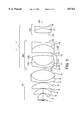
- FIG. 1 is an optical diagram showing general aspects of a microscope objective lens according to the invention as well as specific aspects of Example Embodiment 1.
- FIGS. 2(a)-2(c) are plots, for Example Embodiment 1, of spherical aberration exhibited by the objective lens when used with a cover glass of 0.11, 0.17, and 0.23 mm thickness, respectively.
- FIG. 3 is an optical diagram showing specific aspects of Example Embodiment 2.
- FIGS. 4(a)-4(c) are plots, for Example Embodiment 2, of spherical aberration exhibited by the objective lens when used with a cover glass of 0.08, 0.17, and 0.3 mm thickness, respectively.
- Telephoto-type lenses comprising a front lens group having a positive refractive power and a rear lens group having a negative refractive power force generally have a small angle of view. Telephoto-type lenses are often used with high-magnification lenses having a relatively small angle of view.
- This invention exploits a telephoto-type lens system (i.e., a system comprising a positive lens group on the object side and a negative lens group on the image side) with a relatively high-magnification dry objective lens.
- a representative configuration of an objective lens according to the invention comprises (starting on the object (left) side) a first lens group G1 having positive refractive power, a second lens group G2 having positive refractive power, and a third lens group G3 having negative refractive power.
- the second lens group G2 comprises a first cemented lens L21 having positive refractive power and including a negative lens L2n cemented to a positive lens L2p.
- the first cemented lens L21 has a cemented surface 11 having a strongly negative refractive power. (The power is negative even though the cemented surface has a positive curvature radius because n L21>n L22 .)
- the second lens group G2 also comprises a second cemented lens L22 having negative refractive power.
- the second cemented lens L22 has a cemented surface 14 having a positive refractive power.
- the second lens group G2 and the third lens group G3 are regarded as "corrective" lens groups.
- the cemented surface formed by cementing the lens L2n to L2p is termed the "F surface” which is a term used to denote a cemented surface having a strongly negative refractive power.
- F surface is a term used to denote a cemented surface having a strongly negative refractive power.
- the F surface is located in a corrective lens group.
- the corrective lens group By moving the corrective lens group along the optical axis, the F surface is also moved.
- the height of the entering ray can be adjusted in relation to the F surface. This, in turn, permits various aberrations (especially spherical aberrations) arising from variability in the thickness of the cover glass to be corrected.
- Spherical aberration is proportional to the height (i.e., lateral displacement from the optical axis) of the ray.
- the present invention allows a reduction in the amount of axial distance the corrective lens group has to move in order to increase the available diameter of the F surface.
- n 2n is the refractive index (relative to the D-line) of the negative lens L2n
- n 2p is the refractive index (relative to the D-line) of the positive lens L2p
- D 12 is the axial distance, in air, between the first lens group G1 and the second lens group G2
- f is the focal length for the entire objective lens system.
- the distance D 12 between the first lens group G1 and the second lens group G2 refers to the distance, along the optical axis between the surface in the first lens group G1 that is closest to the image side and the surface in the second lens group G2 that is closest to the object side.
- Conditional expression (1) specifies, within the second lens group G2, an optimal range for the refractive index difference between the negative lens L 2n and the positive lens L 2p . These two lenses are cemented together to form the F surface. Falling below the lower limit of conditional expression (1), causes the refractive-index difference to be too small. Thus, in order to achieve satisfactory correction of spherical aberration, the curvature of the cemented F surface would have to be increased, resulting in unacceptable chromatic aberration.
- Conditional expression (2) relates to the movement range of the corrective lens group (i.e., the second and third lens groups) and specifies an optimal range for the axial distance between the first and second lens groups. Exceeding the upper limit of conditional expression (2) would cause the axial distance between the first and second lens groups to be too great and the balance of lateral chromatic aberration would be lost. (Moving the corrective lens group causes a change in lateral chromatic aberration. Also, if the first and second lens groups become too close together, manufacturing problems arise.
- the first lens group G1 includes at least one positive meniscus lens having a concave surface facing the object side.
- the second lens group G2 includes first and second cemented lenses L21, L22, respectively, as described above.
- the third lens group G3 includes at least one cemented lens.
- Each of the example embodiments described below was evaluated using, on the image side of the objective lens and along the optical axis, a focusing lens.
- the axial air space between the objective lens and the focusing lens was 150 mm.
- the various aberration plots for each example embodiment were generated with the combination of the respective objective lens and the focusing lens as discussed above. However, even if the air space distance were to change slightly from 150 mm, it has been verified that almost no change arises in aberrations.
- the focusing lens used to evaluate the objective lenses comprises, in order from the object side, a cemented positive lens including a biconvex lens cemented to a biconcave lens, and a cemented positive lens including a biconvex lens cemented to a biconcave lens.
- Table 1 below, provides data concerning the focusing lens.
- the left-hand column pertains to surface numbers in order from the object side.
- the second column, designated “r”, pertains to the curvature radius of each lens surface.
- the third column, designated “d”, pertains to the axial distance between adjacent lens surfaces.
- the right-hand column, designated “v d " pertains to the Abbe number of each of the lens elements.
- FIG. 1 depicts specific features of an objective lens according to this example embodiment.
- the first lens group G1 comprises, in order from the object side, a positive meniscus lens (surfaces 1-2) having a concave surface 1 facing the object side, a first positive meniscus lens (surfaces 3-4) with the concave surface 3 facing the object side, a second positive meniscus lens (surfaces 5-6) having a concave surface 5 facing the object side, and a cemented positive lens (surfaces 7-9) including a negative meniscus lens having a convex surface facing the object side and a biconvex lens.
- the second lens group G2 comprises a positive cemented lens L21 including a negative meniscus lens L2n having a convex surface 10 facing the object side and a biconvex lens, and a negative cemented lens L22 including a biconvex lens (surfaces 13-14) and a biconcave lens (surfaces 14-15).
- the cemented surface 11 of the positive cemented lens L21 has a negative refractive power and the cemented surface 14 of the negative cemented lens L22 has a positive refractive power.
- the third lens group G3 comprises a negative cemented lens including a biconcave lens (surfaces 16-17) and a biconvex lens (surfaces 17-18).
- Table 2 presents optical data concerning this first example embodiment.
- f is the focal length of the microscope objective lens (in mm)
- NA is the numerical aperture
- ⁇ is the magnification of a system comprising objective lens and the focusing lens of Table 1
- WD is the working distance (in mm).
- the left-hand column pertains to surface numbers in order from the object side.
- the second column designated “r”, pertains to the curvature radius of each lens surface.
- the third column designated “d”, pertains to the axial distance between adjacent lens surfaces.
- the right-hand column, designated "v d " pertains to the Abbe number of each of the lens elements.
- FIGS. 2(a)-2(c) present spherical aberration plots for the first example embodiment when used with a cover glass of the stated thickness.
- FIG. 2(a) is a plot for a cover-glass thickness of 0.11 mm.
- FIG. 2(b) is a plot for a cover-glass thickness of 0.17 mm.
- FIG. 2(c) is a plot for a cover-glass thickness of 0.23 mm.
- NA is the numerical aperture
- FIG. 3 depicts specific features of an objective lens according to this example embodiment.
- the first lens group G1 comprises, in order from the object side, a positive meniscus lens (surfaces 1-2) having a concave surface 1 facing the object side, a first positive menicus lens (surfaces 3-4) with the concave surface 3 facing the object side, a second positive meniscus lens (surfaces 5-6) having a concave surface 5 facing the object side, and a cemented positive lens (surfaces 7-9) including a negative meniscus lens having a convex surface facing the object side and a biconvex lens.
- the second lens group G2 comprises a positive cemented lens L21 including a negative meniscus lens L2n having a convex surface 10 facing the object side and a biconvex lens, and a negative cemented lens L22 including a biconvex lens (surfaces 13-14) and a biconcave lens (surfaces 14-15).
- the cemented surface 11 of the positive cemented lens L21 has a negative refractive power and the cemented surface 14 of the negative cemented lens L22 has a positive refractive power.
- the third lens group G3 comprises a negative cemented lens including a biconvex lens (surfaces 16-17) and a biconcave lens (surfaces 17-18).
- Table 3 presents optical data concerning this second example embodiment.
- f is the focal length of the microscope objective lens (in mm)
- NA is the numerical aperture
- ⁇ is the magnification of a system comprising objective lens and the focusing lens of Table 1
- WD is the working distance (in mm).
- the left-hand column pertains to surface numbers in order from the object side.
- the second column, designated “r”, pertains to the curvature radius of each lens surface.
- the third column, designated “d”, pertains to the axial distance between adjacent lens surfaces.
- the right-hand column, designated "v d " pertains to the Abbe number of each of the lens elements.
- FIGS. 4(a)-4(c) present spherical aberration plots for the second example embodiment when used with a cover glass of the stated thickness.
- FIG. 4(a) is a plot for a cover-glass thickness of 0.08 mm.
- FIG. 4(b) is a plot for a cover-glass thickness of 0.17 mm.
- FIG. 4(c) is a plot for a cover-glass thickness of 0.3 mm.
- NA is the numerical aperture
- microscope objective lenses according to this invention can provide excellent correction of various aberrations (especially spherical aberration) caused by variability in cover-glass thickness.
- the invention provides apochromatic microscope objective lenses that comprise few component lenses.
Landscapes
- Physics & Mathematics (AREA)
- General Physics & Mathematics (AREA)
- Optics & Photonics (AREA)
- Chemical & Material Sciences (AREA)
- Analytical Chemistry (AREA)
- Lenses (AREA)
Abstract
Apochromatic-type microscope objective lenses are disclosed having a high numeral aperture number with few component lenses. The objective lenses are operable to correct any of various aberrations arising due to use of the objective lens with cover glasses having variable thickness. The objective lenses comprise a first positive lens group comprising a positive meniscus lens with a concave surface facing objectwise, a second positive lens group comprising a positive cemented lens in which the cemented surface has negative refractive power and a negative cemented lens in which the cemented surface has positive refractive power, and a third (negative) lens group comprising at least one cemented lens. The second and third lens groups are movable on the optical axis relative to the first lens group so as to facilitate correction of aberrations arising from use of cover glasses having variable thickness.
Description
This invention pertains to microscope objective lenses, especially apochromatic-type microscope objective lenses.
Generally, microscope objective lenses are designed to be used with a cover glass (i.e., a clear, thin, flat, parallel-plane plate placed between the specimen and the objective lens) of a specific thickness. However, all cover glasses have some variation in thickness, and such variations in thickness can affect the lens performance. The effect of variable cover-glass thickness on lens performance is small if the numerical aperture (NA) of the objective lens is 0.5 or less, and can be pronounced with conventional objective lenses having a numerical aperture of greater than about 0.75.
With conventional objective lenses having a "high" numerical aperture (NA) (i.e., 0.85 or greater), be markedly deleterious, especially with respect to the focusing performance of the lens. This problem can render certain such lenses unsuitable for use.
With certain "brigjt" microscope objective lenses having a high numerical aperture, NA=0.85 or higher, a "correcting" lens group or "correcting ring" is sometimes employed to correct various aberrations arising from variable cover-glass thickness.
Examples of microscope objective lenses including correcting rings are disclosed, e.g., in Japanese Kokai patent document Nos. Sho 61-275812, Hei 3-50517, and Hei 5-119263.
The objective lenses disclosed in the Kokai '812 document comprises a first lens group having a positive refractive power, a second lens group comprising divergent cemented surfaces (i.e., surfaces having negative refractive power) as well as convergent cemented surfaces (i.e., surfaces having positive refractive power), and a third lens group with a negative refractive power. The second and third lens groups comprise a "correcting" lens group that is movable along the optical axis of the objective lens. This microscope objective lens has a numerical aperture NA=0.95, and can maintain nearly maximal brightness when used dry with a cover glass having a thickness range of 0.11 to 0.23 mm. However, such lenses have a problem with variation of chromatic difference of spherical aberration that arises whenever the correcting lens group is moved.
The objective lenses disclosed in the Kokai '517 document comprise, in order from the object side, a first lens group having positive refractive power, a second lens group having positive refractive power, and a third lens group having negative refractive power. The second lens group is movable along the optical axis and purportedly functions as a "correcting" lens group. Unfortunately, the second lens group is composed of four lens elements (three of which are cemented together to form a triplet and one simple lens element) which constitutes too many elements for the lens group to exhibit satisfactory performance as a correcting lens group. Also, the lens diameter is large, which tends to cause problems with aberrations (especially shifts toward the optical axis) arising from eccentricity.
The microscope objective lens disclosed in the Kokai '263 document has a numerical aperture NA=0.93 and includes a correcting lens group consisting of a cemented doublet lens. Unfortunately, however, there are too many lenses (thirteen) in the overall objective lens, which is prohibitively expensive.
The present invention addresses the shortcomings of the prior art discussed above. A key object of the invention is to provide a microscope objective lens having a large numerical aperture and that corrects aberrations, especially spherical aberrations, arising from variability in the cover-glass thickness. Another object is to provide an apochromatic-type microscope objective lens having a relatively small number of lenses and a high numerical aperture.
To such end, microscope objective lenses are provided, according to the invention, that comprise, in order from the object side, a first lens group G1 having a positive refractive power, a second lens group G2 having a positive refracive power, and a third lens group G3 having a negative refractive force. The first lens group G1 comprises a positive meniscus lens having a concave surface facing the object side. The second lens group G2 comprises a first cemented lens L21 with positive refractive power and including a negative lens L2n cemented to a positive lens L2p. The cemented surface has anegative refractive power. The second lens group G2 also comprises a second cemented lens L22 with negative refractive power and having a cemented surface with positive refractive power. The third lens group G3 has at least one cemented lens. The second lens group G2 and the third lens group G3 are axially movable together along the optical axis relative to the first lens group to correct any variable aberrations, especially spherical aberrations, arising from variability in the thickness of the cover glass.
The microscope objective lens of the invention also preferably satisfies the following conditional expressions:
0.33<n.sub.2n -n.sub.2p ( 1)
0.02<D.sub.12 / <1.3 (2)
wherein n2n is the refractive index (relative to the D-line) of the negative lens L2n; n2p is the refractive index (relative to the D-line) of the positive lens L2p; D12 is the axial distance (which can be varied) in air between the first lens group G1 and the second lens group G2; and f is the focal length of the objective lens.
The foregoing and additional features and advantages of the present invention will be more readily apparent from the following detailed description, which proceeds with reference to the accompanying drawings.
FIG. 1 is an optical diagram showing general aspects of a microscope objective lens according to the invention as well as specific aspects of Example Embodiment 1.
FIGS. 2(a)-2(c) are plots, for Example Embodiment 1, of spherical aberration exhibited by the objective lens when used with a cover glass of 0.11, 0.17, and 0.23 mm thickness, respectively.
FIG. 3 is an optical diagram showing specific aspects of Example Embodiment 2.
FIGS. 4(a)-4(c) are plots, for Example Embodiment 2, of spherical aberration exhibited by the objective lens when used with a cover glass of 0.08, 0.17, and 0.3 mm thickness, respectively.
It is generally known that, in order to achieve the best flatness of the image plane, the Petzval sum of the lens should be at or nearly at zero. Certain telephoto lenses are known that achieve a low Petzval sum using a relatively simple configuration. Telephoto-type lenses comprising a front lens group having a positive refractive power and a rear lens group having a negative refractive power force generally have a small angle of view. Telephoto-type lenses are often used with high-magnification lenses having a relatively small angle of view. This invention exploits a telephoto-type lens system (i.e., a system comprising a positive lens group on the object side and a negative lens group on the image side) with a relatively high-magnification dry objective lens.
A representative configuration of an objective lens according to the invention, as shown in FIG. 1, comprises (starting on the object (left) side) a first lens group G1 having positive refractive power, a second lens group G2 having positive refractive power, and a third lens group G3 having negative refractive power.
The second lens group G2 comprises a first cemented lens L21 having positive refractive power and including a negative lens L2n cemented to a positive lens L2p. The first cemented lens L21 has a cemented surface 11 having a strongly negative refractive power. (The power is negative even though the cemented surface has a positive curvature radius because nL21>n L22.) The second lens group G2 also comprises a second cemented lens L22 having negative refractive power. The second cemented lens L22 has a cemented surface 14 having a positive refractive power.
The second lens group G2 and the third lens group G3 are regarded as "corrective" lens groups. Within the second and third lens groups, the cemented surface formed by cementing the lens L2n to L2p is termed the "F surface" which is a term used to denote a cemented surface having a strongly negative refractive power. Generally, by adjusting the height of an entering ray in relation to the F surface, variations in spherical aberration arising from variability in the thickness of the cover glass are corrected.
As indicated above, the F surface is located in a corrective lens group. By moving the corrective lens group along the optical axis, the F surface is also moved. Thus, the height of the entering ray can be adjusted in relation to the F surface. This, in turn, permits various aberrations (especially spherical aberrations) arising from variability in the thickness of the cover glass to be corrected.
Spherical aberration is proportional to the height (i.e., lateral displacement from the optical axis) of the ray. The present invention allows a reduction in the amount of axial distance the corrective lens group has to move in order to increase the available diameter of the F surface.
Objective lenses according to the invention also satisfy the following conditional expressions:
0.33<n.sub.2n -n.sub.2p (1)
0.02<<D.sub.12 /f<1.3 (2)
wherein n2n is the refractive index (relative to the D-line) of the negative lens L2n, n2p is the refractive index (relative to the D-line) of the positive lens L2p, D12 is the axial distance, in air, between the first lens group G1 and the second lens group G2, and f is the focal length for the entire objective lens system.
The distance D12 between the first lens group G1 and the second lens group G2 refers to the distance, along the optical axis between the surface in the first lens group G1 that is closest to the image side and the surface in the second lens group G2 that is closest to the object side.
Conditional expression (1) specifies, within the second lens group G2, an optimal range for the refractive index difference between the negative lens L2n and the positive lens L2p. These two lenses are cemented together to form the F surface. Falling below the lower limit of conditional expression (1), causes the refractive-index difference to be too small. Thus, in order to achieve satisfactory correction of spherical aberration, the curvature of the cemented F surface would have to be increased, resulting in unacceptable chromatic aberration.
Conditional expression (2) relates to the movement range of the corrective lens group (i.e., the second and third lens groups) and specifies an optimal range for the axial distance between the first and second lens groups. Exceeding the upper limit of conditional expression (2) would cause the axial distance between the first and second lens groups to be too great and the balance of lateral chromatic aberration would be lost. (Moving the corrective lens group causes a change in lateral chromatic aberration. Also, if the first and second lens groups become too close together, manufacturing problems arise.
It is desirable to correct the individual lateral chromatic aberration of the first and second lens groups as much as possible.
More specifically with each of the lens groups, the first lens group G1 includes at least one positive meniscus lens having a concave surface facing the object side. The second lens group G2 includes first and second cemented lenses L21, L22, respectively, as described above. The third lens group G3 includes at least one cemented lens.
Each of the example embodiments described below was evaluated using, on the image side of the objective lens and along the optical axis, a focusing lens. The axial air space between the objective lens and the focusing lens was 150 mm.
Also, the various aberration plots for each example embodiment were generated with the combination of the respective objective lens and the focusing lens as discussed above. However, even if the air space distance were to change slightly from 150 mm, it has been verified that almost no change arises in aberrations.
The focusing lens used to evaluate the objective lenses comprises, in order from the object side, a cemented positive lens including a biconvex lens cemented to a biconcave lens, and a cemented positive lens including a biconvex lens cemented to a biconcave lens.
Table 1, below, provides data concerning the focusing lens. In Table 1, the left-hand column pertains to surface numbers in order from the object side. The second column, designated "r", pertains to the curvature radius of each lens surface. The third column, designated "d", pertains to the axial distance between adjacent lens surfaces. The fourth column, designated "nd ", pertains to the refractive index (relative to the D-line; λ=587.63 nm) of each of the lens elements. The right-hand column, designated "vd ", pertains to the Abbe number of each of the lens elements.
              TABLE 1
______________________________________
Surface
No.       r (mm)   d (mm)     n.sub.d
                                    ν.sub.d
______________________________________
21        75.0450  5.1        1.6228
                                    57.03
22        -75.045  2.0        1.7500
                                    35.20
23        1600.5800
                   7.5
24        50.2560  5.1        1.6676
                                    42.00
25        -84.5410 1.8        1.6127
                                    44.41
26        36.9110
______________________________________
FIG. 1 depicts specific features of an objective lens according to this example embodiment.
The first lens group G1 comprises, in order from the object side, a positive meniscus lens (surfaces 1-2) having a concave surface 1 facing the object side, a first positive meniscus lens (surfaces 3-4) with the concave surface 3 facing the object side, a second positive meniscus lens (surfaces 5-6) having a concave surface 5 facing the object side, and a cemented positive lens (surfaces 7-9) including a negative meniscus lens having a convex surface facing the object side and a biconvex lens.
In order from the object side, the second lens group G2 comprises a positive cemented lens L21 including a negative meniscus lens L2n having a convex surface 10 facing the object side and a biconvex lens, and a negative cemented lens L22 including a biconvex lens (surfaces 13-14) and a biconcave lens (surfaces 14-15). The cemented surface 11 of the positive cemented lens L21 has a negative refractive power and the cemented surface 14 of the negative cemented lens L22 has a positive refractive power.
Furthermore, in order from the object side, the third lens group G3 comprises a negative cemented lens including a biconcave lens (surfaces 16-17) and a biconvex lens (surfaces 17-18).
Table 2 presents optical data concerning this first example embodiment. In Table 2, f is the focal length of the microscope objective lens (in mm), NA is the numerical aperture, β is the magnification of a system comprising objective lens and the focusing lens of Table 1, and WD is the working distance (in mm).
In Table 2, the left-hand column pertains to surface numbers in order from the object side. The second column, designated "r", pertains to the curvature radius of each lens surface. The third column, designated "d", pertains to the axial distance between adjacent lens surfaces. The fourth column, designated "nd ", pertains to the refractive index (relative to the D-line; λ=587.63 nm) of each of the lens elements. The right-hand column, designated "vd ", pertains to the Abbe number of each of the lens elements.
              TABLE 2
______________________________________
            f = 5.0 mm
            NA = 0.95
            β = 40x
            WD = 0.14 mm
______________________________________
Surface
No.       r (mm)   d (mm)     n.sub.d
                                    ν.sub.d
______________________________________
1         -2.1418  4.30       1.6935
                                    53.76
2         -3.7147  0.10
3         -15.3747 3.30       1.4978
                                    82.52
4         -7.6264  0.15
5         -34.5141 3.75       1.4978
                                    82.52
6         -12.3011 0.10
7         34.7490  1.15       1.6889
                                    31.08
8         12.2878  7.50       1.4978
                                    95.57
9         -12.2878 (d.sub.9 = D.sub.12 = variable)
10        38.3740  1.15       1.8052
                                    25.35
11        8.4327   6.80       1.4339
                                    95.57
12        -33.7370 1.80
13        203.9400 5.50       1.8052
                                    25.41
14        -10.9804 1.60       1.4339
                                    95.57
15        124.9710 6.60
16        -27.1710 1.00       1.7668
                                    46.80
17        10.4119  3.00       1.5481
                                    45.87
18        -60.8420 150
______________________________________
Values of D.sub.12 For Correction of Aberrations
Cover Glass Thickness
                Variable Distance D.sub.12
______________________________________
0.11 mm          0.65 mm
0.17 mm         1.785 mm
0.23 mm          3.19 mm
______________________________________
Values of Conditional Expressions
______________________________________
          (1) n.sub.2n - n.sub.2p = 0.37
          (2) D.sub.12 /f = 0.13 ˜ 0.638
______________________________________
FIGS. 2(a)-2(c) present spherical aberration plots for the first example embodiment when used with a cover glass of the stated thickness. FIG. 2(a) is a plot for a cover-glass thickness of 0.11 mm. FIG. 2(b) is a plot for a cover-glass thickness of 0.17 mm. FIG. 2(c) is a plot for a cover-glass thickness of 0.23 mm.
In FIGS. 2(a)-2(c), NA is the numerical aperture, d is the D-line (λ=587.63 nm), C is the C-line (λ=656.3 nm) and F is the F-line (λ=486.1 nm).
As is clear from each of the spherical aberration plots for this example embodiment, spherical aberrations arising from changes in the thickness of the cover glass are very well corrected.
FIG. 3 depicts specific features of an objective lens according to this example embodiment.
The first lens group G1 comprises, in order from the object side, a positive meniscus lens (surfaces 1-2) having a concave surface 1 facing the object side, a first positive menicus lens (surfaces 3-4) with the concave surface 3 facing the object side, a second positive meniscus lens (surfaces 5-6) having a concave surface 5 facing the object side, and a cemented positive lens (surfaces 7-9) including a negative meniscus lens having a convex surface facing the object side and a biconvex lens.
In order from the object side, the second lens group G2 comprises a positive cemented lens L21 including a negative meniscus lens L2n having a convex surface 10 facing the object side and a biconvex lens, and a negative cemented lens L22 including a biconvex lens (surfaces 13-14) and a biconcave lens (surfaces 14-15). The cemented surface 11 of the positive cemented lens L21 has a negative refractive power and the cemented surface 14 of the negative cemented lens L22 has a positive refractive power.
Furthermore, in order from the object side, the third lens group G3 comprises a negative cemented lens including a biconvex lens (surfaces 16-17) and a biconcave lens (surfaces 17-18).
Table 3 presents optical data concerning this second example embodiment. In Table 3, f is the focal length of the microscope objective lens (in mm), NA is the numerical aperture, β is the magnification of a system comprising objective lens and the focusing lens of Table 1, and WD is the working distance (in mm).
In Table 3, the left-hand column pertains to surface numbers in order from the object side. The second column, designated "r", pertains to the curvature radius of each lens surface. The third column, designated "d", pertains to the axial distance between adjacent lens surfaces. The fourth column, designated "nd ", pertains to the refractive index (relative to the D-line; λ=587.63 nm) of each of the lens elements. The right-hand column, designated "vd ", pertains to the Abbe number of each of the lens elements.
              TABLE 3
______________________________________
            f = 5.0 mm
            NA = 0.9
            β = 40x
            WD = 0.14 mm
______________________________________
Surface
No.       r (mm)   d (mm)     n.sub.d
                                    ν.sub.d
______________________________________
1         -2.1461  4.25       1.6935
                                    53.76
2         -3.7862  0.10
3         -15.7896 3.30       1.4978
                                    82.52
4         -7.6264  0.15
5         -38.7484 3.75       1.4978
                                    82.52
6         -12.2561 0.10
7         34.7490  1.20       1.6889
                                    31.08
8         12.2881  7.50       1.4978
                                    95.57
9         -12.2933 (d.sub.9 = D.sub.12 = variable)
10        43.1326  1.15       1.8052
                                    25.35
11        8.4532   6.80       1.4339
                                    95.57
12        -32.0003 1.80
13        -411.5836
                   5.50       1.8052
                                    25.41
14        -10.5541 1.60       1.4339
                                    95.57
15        132.4293 6.60
16        41.9894  3.00       1.5481
                                    45.87
17        10.7049  1.00       1.7668
                                    46.80
18        29.1202  150
______________________________________
Values of D.sub.12 For Correction of Aberrations
Cover Glass Thickness
                Variable Distance D.sub.12
______________________________________
0.08 mm         0.39 mm
0.17 mm         1.89 mm
 0.3 mm          4.8 mm
______________________________________
Values of Conditional Expressions
______________________________________
          (1) n.sub.2n - n.sub.2p = 0.37
          (2) D.sub.12 /f = 0.78 ˜ 0.96
______________________________________
FIGS. 4(a)-4(c) present spherical aberration plots for the second example embodiment when used with a cover glass of the stated thickness. FIG. 4(a) is a plot for a cover-glass thickness of 0.08 mm. FIG. 4(b) is a plot for a cover-glass thickness of 0.17 mm. FIG. 4(c) is a plot for a cover-glass thickness of 0.3 mm.
In FIGS. 4(a)-4(c), NA is the numerical aperture, d is the D-line (λ=587.63 nm), C is the C-line (λ=656.3 nm) and F is the F-line (λ=486.1 nm).
As is clear from each of the spherical aberration plots for this example embodiment, spherical aberrations arising from changes in the thickness of the cover glass are very well corrected.
As described above, with a magnification of about 40× and large numerical aperture, microscope objective lenses according to this invention can provide excellent correction of various aberrations (especially spherical aberration) caused by variability in cover-glass thickness. Thus, the invention provides apochromatic microscope objective lenses that comprise few component lenses.
Whereas the invention has been described in connection with several example embodiments, it will be Understood that the invention is not limited to those example embodiments. On the contrary, the invention is intended to encompass all alternatives, modifications, and equivalents as may be included within the spirit and scope of the invention as defined by the appended claims.
Claims (8)
1. A microscope objective lens comprising, on an optical axis from the object side to the image side:
(a) a first lens group (G1) having a positive refractive power, a second lens group (G2) having a positive refractive power, and a third lens group (G3) having a negative refractive power;
(b) the first lens group (G1) comprising first, second, and third positive meniscus lenses each having a concave surface facing the object side;
(c) the second lens group (G2) comprising a first cemented lens (L21) including a negative lens (L2n) cemented to a positive lens (L2p) and a cemented surface having a negative refractive power, and a second cemented lens (L22) including a cemented surface having a positive refractive power;
(d) the third lens group (G3) comprising a cemented lens consisting of a biconcave lens and a biconvex lens;
(e) the second and third lens groups being movable along the optical axis relative to the first lens group so as to correct aberrations arising as a result of using the objective lens with a cover glass having variable thickness; and
(f) the lens satisfying the following conditional expressions:
0.33<n.sub.2n -n.sub.2p
0.02<(D.sub.12)/f<1.3
wherein n2n is the refractive index (relative to the D-line) of the negative lens (L2n), n2p is the refractive index (relative to the D-line) of the positive lens (L2p), (D12) is the axial air space between the first lens group (G1) and the second lens group (G2), and f is the focal length of the objective lens.
2. The microscope objective lens of claim 1, having a mangification of 40×.
3. The microscope objective lens of claim 1, further having the following characteristics:
(a) a focal length f=5.0 mm
(b) a numerical aperture NA=0.95
(c) a magnification β=40×
(d) a working distance WD=0.14 mm
(e) surfaces, curvature radii (r), inter-surface axial distances (d), indices of refraction (nd), and Abbe numbers (vd), as follows:
______________________________________
Surface No.
           r (mm)   d (mm)     n.sub.d
                                     ν.sub.d
______________________________________
1          -2.1418  4.30       1.6935
                                     53.76
2          -3.7147  0.10
3          -15.3747 3.30       1.4978
                                     82.52
4          -7.6264  0.15
5          -34.5141 3.75       1.4978
                                     82.52
6          -12.3011 0.10
7          34.7490  1.15       1.6889
                                     31.08
8          12.2878  7.50       1.4978
                                     95.57
9          -12.2878 (d.sub.9 = D.sub.12 = variable)
10         38.3740  1.15       1.8052
                                     25.35
11         8.4327   6.80       1.4339
                                     95.57
12         -33.7370 1.80
13         203.9400 5.50       1.8052
                                     25.41
14         -10.9804 1.60       1.4339
                                     95.57
15         124.9710 6.60
16         -27.1710 1.00       1.7668
                                     46.80
17         10.4119  3.00       1.5481
                                     45.87
18         -60.8420 150
______________________________________
4. The microscope objective lens of claim 1, wherein the first lens group (G1) further comprises a cemented lens including a negative meniscus lens cemented to a biconvex lens, the cemented lens being situated imagewise of the first, second, and third positive meniscus lenses.
5. The microscope objective lens of claim 1, exhibiting a numerical aperature of at least 0.85.
6. The microscope objective lens of claim 1, wherein the first lens group (G1) further comprises a cemented lens including a negative meniscus lens cemented to a biconvex lens, the cemented lens being situated imagewise of the first positive meniscus lens.
7. The microscope objective lens of claim 1, wherein the second cemented lens (L22) in the second lens group (G2) comprises a biconvex lens cemented to a biconcave lens.
8. The microscope objective lens of claim 1, further having the following characteristics:
(a) a focal length f=5.0 mm
(b) a numerical aperture NA=0.9
(c) a magnification β=40×
(d) a working distance WD=0.14 mm
(e) surfaces, curvature radii (r), inter-surface axial distances (d), indices of refraction (nd), and Abbe numbers (vd), as follows:
______________________________________
Surface No.
           r (mm)   d (mm)     n.sub.d
                                     ν.sub.d
______________________________________
1          -2.1461  4.25       1.6935
                                     53.76
2          -3.7862  0.10
3          -15.7896 3.30       1.4978
                                     82.52
4          -7.6264  0.15
5          -38.7484 3.75       1.4978
                                     82.52
6          -12.2561 0.10
7          34.7490  1.20       1.6889
                                     31.08
8          12.2881  7.50       1.4978
                                     95.57
9          -12.2933 (d.sub.9 = D.sub.12 = variable)
10         43.1326  1.15       1.8052
                                     25.35
11         8.4532   6.80       1.4339
                                     95.57
12         -32.0003 1.80
13         -411.5836
                    5.50       1.8052
                                     25.41
14         -10.5541 1.60       1.4339
                                     95.57
15         132.4293 6.60
16         41.9894  3.00       1.5481
                                     45.87
17         10.7049  1.00       1.7668
                                     46.80
18         29.1202  150
______________________________________
Applications Claiming Priority (2)
| Application Number | Priority Date | Filing Date | Title |
|---|---|---|---|
| JP8-067223 | 1996-02-28 | ||
| JP8067223A JPH09236753A (en) | 1996-02-28 | 1996-02-28 | Microscope objective lens |
Publications (1)
| Publication Number | Publication Date |
|---|---|
| USH1763H true USH1763H (en) | 1998-12-01 |
Family
ID=13338705
Family Applications (1)
| Application Number | Title | Priority Date | Filing Date |
|---|---|---|---|
| US08/805,472 Abandoned USH1763H (en) | 1996-02-28 | 1997-02-25 | Microscope objective lens |
Country Status (2)
| Country | Link |
|---|---|
| US (1) | USH1763H (en) |
| JP (1) | JPH09236753A (en) |
Cited By (5)
| Publication number | Priority date | Publication date | Assignee | Title |
|---|---|---|---|---|
| US20100284065A1 (en) * | 2008-01-23 | 2010-11-11 | Nikon Corporation | Microscope system |
| US20140155694A1 (en) * | 2012-07-03 | 2014-06-05 | Olympus Medical Systems Corp. | Endoscope Objective Optical System |
| CN114488504A (en) * | 2021-12-31 | 2022-05-13 | 宁波永新光学股份有限公司 | Apochromatic objective lens with large numerical aperture |
| CN115031623A (en) * | 2022-05-12 | 2022-09-09 | 中国电子科技集团公司第十一研究所 | A white light interference microscope objective |
| CN118466000A (en) * | 2024-07-15 | 2024-08-09 | 中山市美景光学信息有限公司 | High-power digital microscope optical system that randomly expands the depth of field through autofocus |
Citations (6)
| Publication number | Priority date | Publication date | Assignee | Title |
|---|---|---|---|---|
| US3799680A (en) * | 1972-01-03 | 1974-03-26 | Kollmorgen Corp | Photometer optical system having viewing magnification and light attenuation means |
| JPS61275812A (en) * | 1985-05-31 | 1986-12-05 | Nippon Kogaku Kk <Nikon> | Microscope objective |
| US4666256A (en) * | 1982-11-30 | 1987-05-19 | Nippon Kogaku K. K. | Microscope objective lens |
| JPH06250090A (en) * | 1993-02-24 | 1994-09-09 | Nikon Corp | Microscope objective lens |
| US5444573A (en) * | 1992-12-10 | 1995-08-22 | Olympus Optical Co., Ltd. | Microscope objective |
| US5532878A (en) * | 1994-02-17 | 1996-07-02 | Nikon Corporation | Objective lens system for microscope |
-
1996
- 1996-02-28 JP JP8067223A patent/JPH09236753A/en active Pending
-
1997
- 1997-02-25 US US08/805,472 patent/USH1763H/en not_active Abandoned
Patent Citations (6)
| Publication number | Priority date | Publication date | Assignee | Title |
|---|---|---|---|---|
| US3799680A (en) * | 1972-01-03 | 1974-03-26 | Kollmorgen Corp | Photometer optical system having viewing magnification and light attenuation means |
| US4666256A (en) * | 1982-11-30 | 1987-05-19 | Nippon Kogaku K. K. | Microscope objective lens |
| JPS61275812A (en) * | 1985-05-31 | 1986-12-05 | Nippon Kogaku Kk <Nikon> | Microscope objective |
| US5444573A (en) * | 1992-12-10 | 1995-08-22 | Olympus Optical Co., Ltd. | Microscope objective |
| JPH06250090A (en) * | 1993-02-24 | 1994-09-09 | Nikon Corp | Microscope objective lens |
| US5532878A (en) * | 1994-02-17 | 1996-07-02 | Nikon Corporation | Objective lens system for microscope |
Non-Patent Citations (6)
| Title |
|---|
| English Abstract of Japanese reference No. 5 119263, issued on May 18, 1993. * |
| English Abstract of Japanese reference No. 5 50517, issued on Mar. 5, 1991. * |
| English Abstract of Japanese reference No. 5-119263, issued on May 18, 1993. |
| English Abstract of Japanese reference No. 5-50517, issued on Mar. 5, 1991. |
| English Abstract of Japanese reference No. 61 275,812, issued on Dec. 5, 1986. * |
| English Abstract of Japanese reference No. 61-275,812, issued on Dec. 5, 1986. |
Cited By (8)
| Publication number | Priority date | Publication date | Assignee | Title |
|---|---|---|---|---|
| US20100284065A1 (en) * | 2008-01-23 | 2010-11-11 | Nikon Corporation | Microscope system |
| US8098427B2 (en) | 2008-01-23 | 2012-01-17 | Nikon Corporation | Microscopic insemination viewing method |
| US20140155694A1 (en) * | 2012-07-03 | 2014-06-05 | Olympus Medical Systems Corp. | Endoscope Objective Optical System |
| US9372336B2 (en) * | 2012-07-03 | 2016-06-21 | Olympus Corporation | Endoscope objective optical system |
| CN114488504A (en) * | 2021-12-31 | 2022-05-13 | 宁波永新光学股份有限公司 | Apochromatic objective lens with large numerical aperture |
| CN114488504B (en) * | 2021-12-31 | 2024-01-16 | 宁波永新光学股份有限公司 | A large numerical aperture apochromatic objective lens |
| CN115031623A (en) * | 2022-05-12 | 2022-09-09 | 中国电子科技集团公司第十一研究所 | A white light interference microscope objective |
| CN118466000A (en) * | 2024-07-15 | 2024-08-09 | 中山市美景光学信息有限公司 | High-power digital microscope optical system that randomly expands the depth of field through autofocus |
Also Published As
| Publication number | Publication date |
|---|---|
| JPH09236753A (en) | 1997-09-09 |
Similar Documents
| Publication | Publication Date | Title |
|---|---|---|
| US20060056047A1 (en) | Wide zoom lens system | |
| US5636067A (en) | Taking lens system | |
| JP3313163B2 (en) | Microscope objective lens | |
| US4666256A (en) | Microscope objective lens | |
| US5113287A (en) | Compact zoom lens with positive power front lens group and negative power rear lens group | |
| JP3735909B2 (en) | Retro focus lens | |
| US5519540A (en) | Taking lens for underwater camera | |
| US4588264A (en) | Microscope objective lens | |
| US5978147A (en) | Immersion microscope objective | |
| US5798869A (en) | Immersion-type microscope objective lens | |
| USH1763H (en) | Microscope objective lens | |
| US6128139A (en) | Microscope objective lens | |
| US5757552A (en) | Microscope objective lens and a microscope incorporating same | |
| US5729391A (en) | Microscope objective lens | |
| US5696633A (en) | Varifocal lens | |
| JP3140497B2 (en) | Wide-field eyepiece | |
| US5080473A (en) | Vari-focal lens system | |
| JP4032502B2 (en) | Large aperture ratio in-focus super telephoto lens | |
| US4417787A (en) | Five-component microscope objective | |
| US5532879A (en) | Microscope objective lens | |
| JP3242451B2 (en) | Microscope objective lens | |
| US4383739A (en) | Microscope objective | |
| JPH09138351A (en) | Low magnification microscope objective lens | |
| JPH0567003B2 (en) | ||
| JPH0567002B2 (en) |
Legal Events
| Date | Code | Title | Description |
|---|---|---|---|
| AS | Assignment |
Owner name: NIKON CORPORATION, JAPAN Free format text: ASSIGNMENT OF ASSIGNORS INTEREST;ASSIGNOR:MIZUSAWA, MASAYUKI;REEL/FRAME:008396/0879 Effective date: 19970212 |
|
| STCF | Information on status: patent grant |
Free format text: PATENTED CASE |