US9975813B2 - Proppants and methods of making the same - Google Patents
Proppants and methods of making the same Download PDFInfo
- Publication number
- US9975813B2 US9975813B2 US14/903,457 US201414903457A US9975813B2 US 9975813 B2 US9975813 B2 US 9975813B2 US 201414903457 A US201414903457 A US 201414903457A US 9975813 B2 US9975813 B2 US 9975813B2
- Authority
- US
- United States
- Prior art keywords
- core
- proppant
- shell
- green body
- ceramic
- Prior art date
- Legal status (The legal status is an assumption and is not a legal conclusion. Google has not performed a legal analysis and makes no representation as to the accuracy of the status listed.)
- Expired - Fee Related, expires
Links
Images


Classifications
-
- C—CHEMISTRY; METALLURGY
- C04—CEMENTS; CONCRETE; ARTIFICIAL STONE; CERAMICS; REFRACTORIES
- C04B—LIME, MAGNESIA; SLAG; CEMENTS; COMPOSITIONS THEREOF, e.g. MORTARS, CONCRETE OR LIKE BUILDING MATERIALS; ARTIFICIAL STONE; CERAMICS; REFRACTORIES; TREATMENT OF NATURAL STONE
- C04B35/00—Shaped ceramic products characterised by their composition; Ceramics compositions; Processing powders of inorganic compounds preparatory to the manufacturing of ceramic products
- C04B35/515—Shaped ceramic products characterised by their composition; Ceramics compositions; Processing powders of inorganic compounds preparatory to the manufacturing of ceramic products based on non-oxide ceramics
- C04B35/52—Shaped ceramic products characterised by their composition; Ceramics compositions; Processing powders of inorganic compounds preparatory to the manufacturing of ceramic products based on non-oxide ceramics based on carbon, e.g. graphite
-
- C—CHEMISTRY; METALLURGY
- C04—CEMENTS; CONCRETE; ARTIFICIAL STONE; CERAMICS; REFRACTORIES
- C04B—LIME, MAGNESIA; SLAG; CEMENTS; COMPOSITIONS THEREOF, e.g. MORTARS, CONCRETE OR LIKE BUILDING MATERIALS; ARTIFICIAL STONE; CERAMICS; REFRACTORIES; TREATMENT OF NATURAL STONE
- C04B35/00—Shaped ceramic products characterised by their composition; Ceramics compositions; Processing powders of inorganic compounds preparatory to the manufacturing of ceramic products
- C04B35/01—Shaped ceramic products characterised by their composition; Ceramics compositions; Processing powders of inorganic compounds preparatory to the manufacturing of ceramic products based on oxide ceramics
- C04B35/16—Shaped ceramic products characterised by their composition; Ceramics compositions; Processing powders of inorganic compounds preparatory to the manufacturing of ceramic products based on oxide ceramics based on silicates other than clay
- C04B35/18—Shaped ceramic products characterised by their composition; Ceramics compositions; Processing powders of inorganic compounds preparatory to the manufacturing of ceramic products based on oxide ceramics based on silicates other than clay rich in aluminium oxide
- C04B35/195—Alkaline earth aluminosilicates, e.g. cordierite or anorthite
-
- C—CHEMISTRY; METALLURGY
- C04—CEMENTS; CONCRETE; ARTIFICIAL STONE; CERAMICS; REFRACTORIES
- C04B—LIME, MAGNESIA; SLAG; CEMENTS; COMPOSITIONS THEREOF, e.g. MORTARS, CONCRETE OR LIKE BUILDING MATERIALS; ARTIFICIAL STONE; CERAMICS; REFRACTORIES; TREATMENT OF NATURAL STONE
- C04B35/00—Shaped ceramic products characterised by their composition; Ceramics compositions; Processing powders of inorganic compounds preparatory to the manufacturing of ceramic products
- C04B35/622—Forming processes; Processing powders of inorganic compounds preparatory to the manufacturing of ceramic products
- C04B35/626—Preparing or treating the powders individually or as batches ; preparing or treating macroscopic reinforcing agents for ceramic products, e.g. fibres; mechanical aspects section B
- C04B35/628—Coating the powders or the macroscopic reinforcing agents
- C04B35/62802—Powder coating materials
- C04B35/62805—Oxide ceramics
- C04B35/62813—Alumina or aluminates
-
- C—CHEMISTRY; METALLURGY
- C04—CEMENTS; CONCRETE; ARTIFICIAL STONE; CERAMICS; REFRACTORIES
- C04B—LIME, MAGNESIA; SLAG; CEMENTS; COMPOSITIONS THEREOF, e.g. MORTARS, CONCRETE OR LIKE BUILDING MATERIALS; ARTIFICIAL STONE; CERAMICS; REFRACTORIES; TREATMENT OF NATURAL STONE
- C04B35/00—Shaped ceramic products characterised by their composition; Ceramics compositions; Processing powders of inorganic compounds preparatory to the manufacturing of ceramic products
- C04B35/622—Forming processes; Processing powders of inorganic compounds preparatory to the manufacturing of ceramic products
- C04B35/626—Preparing or treating the powders individually or as batches ; preparing or treating macroscopic reinforcing agents for ceramic products, e.g. fibres; mechanical aspects section B
- C04B35/628—Coating the powders or the macroscopic reinforcing agents
- C04B35/62802—Powder coating materials
- C04B35/62828—Non-oxide ceramics
- C04B35/62839—Carbon
-
- C—CHEMISTRY; METALLURGY
- C04—CEMENTS; CONCRETE; ARTIFICIAL STONE; CERAMICS; REFRACTORIES
- C04B—LIME, MAGNESIA; SLAG; CEMENTS; COMPOSITIONS THEREOF, e.g. MORTARS, CONCRETE OR LIKE BUILDING MATERIALS; ARTIFICIAL STONE; CERAMICS; REFRACTORIES; TREATMENT OF NATURAL STONE
- C04B35/00—Shaped ceramic products characterised by their composition; Ceramics compositions; Processing powders of inorganic compounds preparatory to the manufacturing of ceramic products
- C04B35/622—Forming processes; Processing powders of inorganic compounds preparatory to the manufacturing of ceramic products
- C04B35/64—Burning or sintering processes
-
- C—CHEMISTRY; METALLURGY
- C04—CEMENTS; CONCRETE; ARTIFICIAL STONE; CERAMICS; REFRACTORIES
- C04B—LIME, MAGNESIA; SLAG; CEMENTS; COMPOSITIONS THEREOF, e.g. MORTARS, CONCRETE OR LIKE BUILDING MATERIALS; ARTIFICIAL STONE; CERAMICS; REFRACTORIES; TREATMENT OF NATURAL STONE
- C04B35/00—Shaped ceramic products characterised by their composition; Ceramics compositions; Processing powders of inorganic compounds preparatory to the manufacturing of ceramic products
- C04B35/71—Ceramic products containing macroscopic reinforcing agents
- C04B35/78—Ceramic products containing macroscopic reinforcing agents containing non-metallic materials
-
- C—CHEMISTRY; METALLURGY
- C04—CEMENTS; CONCRETE; ARTIFICIAL STONE; CERAMICS; REFRACTORIES
- C04B—LIME, MAGNESIA; SLAG; CEMENTS; COMPOSITIONS THEREOF, e.g. MORTARS, CONCRETE OR LIKE BUILDING MATERIALS; ARTIFICIAL STONE; CERAMICS; REFRACTORIES; TREATMENT OF NATURAL STONE
- C04B38/00—Porous mortars, concrete, artificial stone or ceramic ware; Preparation thereof
- C04B38/009—Porous or hollow ceramic granular materials, e.g. microballoons
-
- C—CHEMISTRY; METALLURGY
- C09—DYES; PAINTS; POLISHES; NATURAL RESINS; ADHESIVES; COMPOSITIONS NOT OTHERWISE PROVIDED FOR; APPLICATIONS OF MATERIALS NOT OTHERWISE PROVIDED FOR
- C09K—MATERIALS FOR MISCELLANEOUS APPLICATIONS, NOT PROVIDED FOR ELSEWHERE
- C09K8/00—Compositions for drilling of boreholes or wells; Compositions for treating boreholes or wells, e.g. for completion or for remedial operations
- C09K8/60—Compositions for stimulating production by acting on the underground formation
- C09K8/80—Compositions for reinforcing fractures, e.g. compositions of proppants used to keep the fractures open
-
- C—CHEMISTRY; METALLURGY
- C04—CEMENTS; CONCRETE; ARTIFICIAL STONE; CERAMICS; REFRACTORIES
- C04B—LIME, MAGNESIA; SLAG; CEMENTS; COMPOSITIONS THEREOF, e.g. MORTARS, CONCRETE OR LIKE BUILDING MATERIALS; ARTIFICIAL STONE; CERAMICS; REFRACTORIES; TREATMENT OF NATURAL STONE
- C04B2235/00—Aspects relating to ceramic starting mixtures or sintered ceramic products
- C04B2235/02—Composition of constituents of the starting material or of secondary phases of the final product
- C04B2235/30—Constituents and secondary phases not being of a fibrous nature
- C04B2235/34—Non-metal oxides, non-metal mixed oxides, or salts thereof that form the non-metal oxides upon heating, e.g. carbonates, nitrates, (oxy)hydroxides, chlorides
- C04B2235/3427—Silicates other than clay, e.g. water glass
- C04B2235/3463—Alumino-silicates other than clay, e.g. mullite
- C04B2235/3481—Alkaline earth metal alumino-silicates other than clay, e.g. cordierite, beryl, micas such as margarite, plagioclase feldspars such as anorthite, zeolites such as chabazite
-
- C—CHEMISTRY; METALLURGY
- C04—CEMENTS; CONCRETE; ARTIFICIAL STONE; CERAMICS; REFRACTORIES
- C04B—LIME, MAGNESIA; SLAG; CEMENTS; COMPOSITIONS THEREOF, e.g. MORTARS, CONCRETE OR LIKE BUILDING MATERIALS; ARTIFICIAL STONE; CERAMICS; REFRACTORIES; TREATMENT OF NATURAL STONE
- C04B2235/00—Aspects relating to ceramic starting mixtures or sintered ceramic products
- C04B2235/02—Composition of constituents of the starting material or of secondary phases of the final product
- C04B2235/30—Constituents and secondary phases not being of a fibrous nature
- C04B2235/42—Non metallic elements added as constituents or additives, e.g. sulfur, phosphor, selenium or tellurium
- C04B2235/422—Carbon
-
- C—CHEMISTRY; METALLURGY
- C04—CEMENTS; CONCRETE; ARTIFICIAL STONE; CERAMICS; REFRACTORIES
- C04B—LIME, MAGNESIA; SLAG; CEMENTS; COMPOSITIONS THEREOF, e.g. MORTARS, CONCRETE OR LIKE BUILDING MATERIALS; ARTIFICIAL STONE; CERAMICS; REFRACTORIES; TREATMENT OF NATURAL STONE
- C04B2235/00—Aspects relating to ceramic starting mixtures or sintered ceramic products
- C04B2235/02—Composition of constituents of the starting material or of secondary phases of the final product
- C04B2235/50—Constituents or additives of the starting mixture chosen for their shape or used because of their shape or their physical appearance
- C04B2235/52—Constituents or additives characterised by their shapes
- C04B2235/528—Spheres
-
- C—CHEMISTRY; METALLURGY
- C04—CEMENTS; CONCRETE; ARTIFICIAL STONE; CERAMICS; REFRACTORIES
- C04B—LIME, MAGNESIA; SLAG; CEMENTS; COMPOSITIONS THEREOF, e.g. MORTARS, CONCRETE OR LIKE BUILDING MATERIALS; ARTIFICIAL STONE; CERAMICS; REFRACTORIES; TREATMENT OF NATURAL STONE
- C04B2235/00—Aspects relating to ceramic starting mixtures or sintered ceramic products
- C04B2235/02—Composition of constituents of the starting material or of secondary phases of the final product
- C04B2235/50—Constituents or additives of the starting mixture chosen for their shape or used because of their shape or their physical appearance
- C04B2235/54—Particle size related information
- C04B2235/5418—Particle size related information expressed by the size of the particles or aggregates thereof
- C04B2235/5427—Particle size related information expressed by the size of the particles or aggregates thereof millimeter or submillimeter sized, i.e. larger than 0,1 mm
-
- C—CHEMISTRY; METALLURGY
- C04—CEMENTS; CONCRETE; ARTIFICIAL STONE; CERAMICS; REFRACTORIES
- C04B—LIME, MAGNESIA; SLAG; CEMENTS; COMPOSITIONS THEREOF, e.g. MORTARS, CONCRETE OR LIKE BUILDING MATERIALS; ARTIFICIAL STONE; CERAMICS; REFRACTORIES; TREATMENT OF NATURAL STONE
- C04B2235/00—Aspects relating to ceramic starting mixtures or sintered ceramic products
- C04B2235/02—Composition of constituents of the starting material or of secondary phases of the final product
- C04B2235/50—Constituents or additives of the starting mixture chosen for their shape or used because of their shape or their physical appearance
- C04B2235/54—Particle size related information
- C04B2235/5463—Particle size distributions
- C04B2235/5472—Bimodal, multi-modal or multi-fraction
-
- C—CHEMISTRY; METALLURGY
- C04—CEMENTS; CONCRETE; ARTIFICIAL STONE; CERAMICS; REFRACTORIES
- C04B—LIME, MAGNESIA; SLAG; CEMENTS; COMPOSITIONS THEREOF, e.g. MORTARS, CONCRETE OR LIKE BUILDING MATERIALS; ARTIFICIAL STONE; CERAMICS; REFRACTORIES; TREATMENT OF NATURAL STONE
- C04B2235/00—Aspects relating to ceramic starting mixtures or sintered ceramic products
- C04B2235/60—Aspects relating to the preparation, properties or mechanical treatment of green bodies or pre-forms
- C04B2235/602—Making the green bodies or pre-forms by moulding
- C04B2235/6028—Shaping around a core which is removed later
-
- C—CHEMISTRY; METALLURGY
- C04—CEMENTS; CONCRETE; ARTIFICIAL STONE; CERAMICS; REFRACTORIES
- C04B—LIME, MAGNESIA; SLAG; CEMENTS; COMPOSITIONS THEREOF, e.g. MORTARS, CONCRETE OR LIKE BUILDING MATERIALS; ARTIFICIAL STONE; CERAMICS; REFRACTORIES; TREATMENT OF NATURAL STONE
- C04B2235/00—Aspects relating to ceramic starting mixtures or sintered ceramic products
- C04B2235/60—Aspects relating to the preparation, properties or mechanical treatment of green bodies or pre-forms
- C04B2235/608—Green bodies or pre-forms with well-defined density
-
- C—CHEMISTRY; METALLURGY
- C04—CEMENTS; CONCRETE; ARTIFICIAL STONE; CERAMICS; REFRACTORIES
- C04B—LIME, MAGNESIA; SLAG; CEMENTS; COMPOSITIONS THEREOF, e.g. MORTARS, CONCRETE OR LIKE BUILDING MATERIALS; ARTIFICIAL STONE; CERAMICS; REFRACTORIES; TREATMENT OF NATURAL STONE
- C04B2235/00—Aspects relating to ceramic starting mixtures or sintered ceramic products
- C04B2235/70—Aspects relating to sintered or melt-casted ceramic products
- C04B2235/74—Physical characteristics
- C04B2235/77—Density
- C04B2235/775—Products showing a density-gradient
-
- C—CHEMISTRY; METALLURGY
- C04—CEMENTS; CONCRETE; ARTIFICIAL STONE; CERAMICS; REFRACTORIES
- C04B—LIME, MAGNESIA; SLAG; CEMENTS; COMPOSITIONS THEREOF, e.g. MORTARS, CONCRETE OR LIKE BUILDING MATERIALS; ARTIFICIAL STONE; CERAMICS; REFRACTORIES; TREATMENT OF NATURAL STONE
- C04B2235/00—Aspects relating to ceramic starting mixtures or sintered ceramic products
- C04B2235/70—Aspects relating to sintered or melt-casted ceramic products
- C04B2235/94—Products characterised by their shape
-
- C—CHEMISTRY; METALLURGY
- C04—CEMENTS; CONCRETE; ARTIFICIAL STONE; CERAMICS; REFRACTORIES
- C04B—LIME, MAGNESIA; SLAG; CEMENTS; COMPOSITIONS THEREOF, e.g. MORTARS, CONCRETE OR LIKE BUILDING MATERIALS; ARTIFICIAL STONE; CERAMICS; REFRACTORIES; TREATMENT OF NATURAL STONE
- C04B2235/00—Aspects relating to ceramic starting mixtures or sintered ceramic products
- C04B2235/70—Aspects relating to sintered or melt-casted ceramic products
- C04B2235/96—Properties of ceramic products, e.g. mechanical properties such as strength, toughness, wear resistance
- C04B2235/9607—Thermal properties, e.g. thermal expansion coefficient
Definitions
- the present invention relates to proppants and methods of making proppants.
- the present invention further relates to the use of proppants for hydrocarbon recovery.
- the present invention further relates to the method of fracking a well using the proppants of the present invention.
- Proppants are materials pumped into oil or gas wells at extreme pressure in a carrier solution (typically brine) during the hydrofracturing process. Once the pumping-induced pressure is removed, proppants “prop” open fractures in the rock formation and thus preclude the fracture from closing. As a result, the amount of formation surface area exposed to the well bore is increased, enhancing recovery rates.
- a carrier solution typically brine
- Ceramic proppants are widely used as propping agents to maintain permeability in oil and gas formations.
- High strength ceramic proppants have been used in the hydrofracture of subterranean earth in order to improve production of natural gas and/or oil.
- the proppant beads need to withstand 10 kpsi or higher pressure to be effective to prop the fracture generated by the hydrofracture process.
- proppants formed from high strength materials such as sintered bauxite and alumina have sufficient compressive and flexural strength for use in deep wells.
- These conventional high strength materials are expensive, however, because of a limited supply of raw materials, a high requirement for purity, and the complex nature of the manufacturing process.
- a feature of the present invention is to provide new methods to make ceramic core/shell proppants where the core can include a hollow portion that is created during sintering of a solid green body core and a solid green body shell.
- a feature of the present invention is to provide proppants having a balance of strength properties from the shell and the core.
- the present invention relates to a green body proppant that can include a green body core comprising glassy material; and a green body shell surrounding the green body core and comprising coarse particles.
- a proppant is provided by the present invention that can include a porous core, and a shell surrounding the transition region, the shell including a transition region surrounded by an outer shell, wherein an average transition region density is greater than an average outer shell density, the average outer shell density is greater than an average core density, and the transition region has a glassy phase content of at least 1 vol % based on the total volume of the transition region, such as at least 15 vol %.
- the present invention further relates to a method of making a sintered ceramic proppant.
- a substantially spherical green body core can be formed that contains one or more ceramic particulate materials including at least one glassy material.
- a green body shell can be formed around the green body core, wherein the green body shell contains at least one ceramic particulate material that results in a green core/shell body.
- the green core/shell body can be sintered and, during sintering, at least a portion of said green body core can be diffused or otherwise enter into the green body shell to form a sintered ceramic proppant comprising a porous core, a transition region surrounding the core, and an outer shell surrounding the transition region, wherein an average transition region density is greater than an average outer shell density, the average outer shell density is greater than an average core density, and the transition region has a glassy phase content of at least 5 vol % based on the total volume of the transition region.
- the present invention relates to a green body proppant that includes a core and/or shell, wherein the green body proppant includes a chemical gradient having a plurality of stages across the core, the shell, or both.
- the present invention also relates to a method of forming a sintered proppant that can include forming a green body proppant containing a core, a shell, or both; creating a chemical gradient in the green body proppant during the formation; and sintering the green body to form a sintered proppant.
- a method of forming a sintered proppant is further provided that can include forming a green body proppant containing a core, a shell, or both; and adjusting the coefficient of thermal expansion (CTE) to strengthen the compressive strength of the resulting sintered proppant sufficient to partially or completely cancel out tensile strength of an external load applied to the resulting proppant.
- CTE coefficient of thermal expansion
- the present invention also relates to a green body proppant that contains a carbide or any combination of carbides in the form of rods, whiskers, platelets, or any combination thereof in an amount effective to strengthen a sintered proppant formed from the green body proppant, wherein the green body proppant comprises a core, a shell, or any combination thereof.
- a green body proppant is also provided that includes alumina and additionally silicon carbide, potassium titanate, hydrotalcite, partially stabilized zirconia, or any combination thereof.
- the present invention further provides a method of forming a silicon carbide-toughened ceramic composite proppant.
- a green body can be formed containing silicon carbide particles, the green body comprising a core, a shell, or both.
- the green body can be heated under controlled heating conditions.
- the heated green body can be sintered at an elevated temperature to form a silicon carbide-toughened ceramic composite proppant.
- Sintered proppants formed from the green bodies and/or using the methods of the present invention are also provided.
- the present invention relates to proppants that contain graphene and methods of producing the same.
- Graphene-toughened ceramic proppants and methods of forming a graphene-toughened ceramic proppant are provided in which, for example, a green body containing graphene is formed, the green body including a core, a shell, or both; heating the green body under controlled heating conditions; and sintering the heated green body at an elevated temperature to form a graphene-toughened ceramic proppant.
- Conductive proppants and methods of forming a conductive ceramic proppant are provided in which, for example, a green body containing graphene is formed, the green body including a core, a shell, or both; heating the green body under controlled heating conditions; and sintering the heated green body at an elevated temperature to form a conductive ceramic proppant.
- Conductive ceramic proppants can be thermally conductive, electrically conductive, or both.
- the present invention further relates to a method to prop open subterranean formation fractures by utilizing the proppants of the present invention.
- the proppant population of the present invention can be combined with one or more fluids to form a suspension, which can then be pumped into the subterranean producing zone. Further details are provided herein.
- FIG. 1 is a diagram of a proppant (enlarged) that shows the schematics of void formation in the center of the proppant in the core region due to the partial or complete diffusion or migration of the core material from the green body and further shows the diffusion or migration of the core material into the shell regions.
- FIG. 1 shows that the diffusion or migration of the core material forms a type of gradient and, therefore, a higher concentration of core material is present closer to the core than the outer surface of the proppant, with migration or diffusion of the core material occurring in an outward radial direction.
- FIG. 1 also comprises three graphs that show the degree of porosity, core material concentration, and mullite whisker formation/concentration based on location within the proppant. The three graphs are in alignment with the location shown in the proppant sphere diagram or drawing.
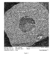
- FIG. 2 is a SEM image of the cross-section of an example of a ceramic synthetic proppant of the present invention, showing the fractured surface with a hollow core formed by outward radial diffusion (or migration) of at least a portion of the core during sintering.
- FIG. 3 is a SEM image at a higher magnification of FIG. 2 of the cross-section of the ceramic synthetic proppant of the present invention, showing the fractured surface with a hollow core formed by outward radial diffusion (or migration) of at least a portion of the core during sintering.
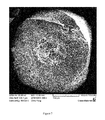
- FIG. 4 is a SEM image of the cross-section of an example of a ceramic synthetic proppant of the present invention, showing the fractured surface with a porous core or hollow regions formed by outward radial diffusion (or migration) of a small portion of the core during sintering.
- the diffusion (or migration) here was less than in FIG. 2 , thus no hollow core resulted, but instead a plurality of hollow regions or porous areas.
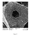
- FIG. 5 is a SEM image of the cross-section of an example of a ceramic synthetic proppant of the present invention, showing the fractured surface with a hollow core formed by outward radial diffusion (or migration) of at least a portion of the core during sintering.
- the hollow core formation was irregular and less than in FIG. 2 .
- FIG. 6 is a fracture cross section of a proppant with a dense core of formula 1 (high melting formulation) in Table DA-1.
- FIG. 7 is a fracture cross section of a proppant with a porous core of formula 2 in Table DA-1.
- FIG. 8 is a fracture cross section of a proppant with a relatively solid core of formula 3 in Table DA-1.
- FIG. 9 is a fracture cross section of a proppant with a hollow core of formula 4 in Table DA-1. A hollow core of low sphericity was formed. A diffusion region between the inner shell and the matrix of the outer shell is visible.
- FIG. 10 is a fracture cross section of a proppant with a hollow core of formula 5 in Table DA-1. A diffusion region between the inner shell and the outer shell is clearly shown in the image.
- the resultant hollow core is highly spherical, with a dense inner shell and smooth inner surface that are essentially free from macro structural defects.
- FIG. 11 is a schematic diagram of a proppant bead depicting infiltration of glass from the core into the shell of the proppant bead.
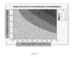
- FIG. 12 is a contour plot of R/b v. fraction reacted, fraction solids core.
- FIG. 13 is a surface plot of R/b v. fraction reacted, fraction solids shell.
- FIG. 14 is a schematic diagram of capillarity as a driving force for infiltration.
- FIG. 15 is a graph of R/b growth of the infiltration zone v. time.
- the present invention relates to a proppant, populations of proppants, methods of making the proppants, and uses for the proppants, including using the proppants in hydrocarbon recovery.
- a ceramic proppant is a proppant that contains at least 90% by weight ceramic materials based on the entire weight of the ceramic proppant.
- the ceramic proppant can contain at least 92% by weight ceramic materials, at least 95% by weight ceramic materials, at least 96% by weight ceramic materials, at least 97% by weight ceramic materials, at least 98% by weight ceramic materials, at least 99% by weight ceramic materials, at least 99.5% by weight ceramic materials, at least 99.9% by weight ceramic materials, or can be 100% by weight ceramic materials.
- the ceramic materials can be one or more metal oxides, and/or one or more non-oxides that are considered ceramics, such as carbides, borides, nitrides, and/or silicides.
- the term “ceramic” includes glass material, ceramic material, and/or glass-ceramic material and/or can comprise one or more glass, ceramic, and/or glass-ceramic phases.
- the “ceramic” material can be non-crystalline, crystalline, and/or partially crystalline.
- the ceramic proppant can have less than 5 wt % polymeric and/or cellulosic (e.g., plant material or tree material). More preferably, the proppants of the present invention have less than 1 wt %, less than 0.5 wt %, less than 0.1 wt %, or 0 wt % of polymeric material or cellulosic material or both in the sintered proppants of the present invention.
- the ceramic in the ceramic proppants of the present invention can be an oxide, such as aluminum oxides (alumina) and/or mixed metal aluminum oxides, such as metal aluminates containing calcium, yttrium, titanium, lanthanum, barium, and/or silicon in addition to aluminum.
- the ceramic can be an oxide, such as aluminum oxide called alumina, or a mixed metal oxide of aluminum called an aluminate, a silicate, or an aluminosilicate, such as mullite or cordierite.
- the aluminate or the ceramic in general may contain magnesium, calcium, yttrium, titanium, lanthanum, barium, and/or silicon.
- the ceramic may be formed from a nanoparticle precursor such as an alumoxane.
- Alumoxanes can be chemically functionalized aluminum oxide nanoparticles with surface groups including those derived from carboxylic acids such as acetate, methoxyacetate, methoxyethoxyacetate, methoxyethoxyethoxyacetate, lysine, and stearate, and the like.
- the ceramic can include, but is not limited to, boehmite, alumina, spinel, alumnosilicate clays (e.g., kaolin, montmorillonite, bentonite, and the like), calcium carbonate, calcium oxide, magnesium oxide, magnesium carbonate, cordierite, spinel, spodumene, steatite, a silicate, a substituted alumino silicate clay or any combination thereof (e.g. kyanite) and the like.
- boehmite e.g., kaolin, montmorillonite, bentonite, and the like
- calcium carbonate calcium oxide, magnesium oxide, magnesium carbonate, cordierite, spinel, spodumene, steatite
- silicate a substituted alumino silicate clay or any combination thereof (e.g. kyanite) and the like.
- the ceramic can be or contain cordierite, mullite, bauxite, silica, spodumene, clay, silicon oxide, aluminum oxide, sodium oxide, potassium oxide, calcium oxide, zirconium oxide, lithium oxide, iron oxide, spinel, steatite, a silicate, a substituted alumino silicate clay, an inorganic nitride, an inorganic carbide or a non-oxide ceramic or any mixtures thereof.
- the proppant can include or be one or more sedimentary and/or synthetically produced materials.
- Glass-ceramic refers to any glass-ceramic that is formed when glass or a substantially glassy material is annealed at elevated temperature to produce a substantially crystalline material, such as with limited crystallinity or controlled crystallite size.
- limited crystallinity should be understood as crystallinity of from about 5% to about 100%, by volume (e.g., 10% to 90%; 20% to 80%; 30% to 70%; 40% to 60% by volume).
- the crystallite size can be from about 0.01 micrometers to 20 micrometers, such as 0.1 to 5 micrometers. Preferably the crystallite size is less than 1 micrometer.
- the glass-ceramic can be composed of aluminum oxide, silicon oxide, boron oxide, potassium oxide, zirconium oxide, magnesium oxide, calcium oxide, lithium oxide, phosphorous oxide, and/or titanium oxide or any combination thereof.
- the glass-ceramic can comprise from about 35% to about 55% by weight SiO 2 ; from about 18% to about 28% by weight Al 2 O 3 ; from about 1% to about 15% by weight (e.g., 1 to 5 wt %) CaO; from about 7% to about 14% by weight MgO; from about 0.5% to about 15% by weight TiO 2 (e.g., 0.5 to 5 wt %); from about 0.4% to about 3% by weight B 2 O 3 , and/or greater than 0% by weight and up to about 1% by weight P 2 O 5 , all based on the total weight of the glass-ceramic.
- the glass-ceramic can comprise from about 3% to about 5% by weight Li 2 O; from about 0% to about 15% by weight Al 2 O 3 ; from about 10% to about 45% by weight SiO 2 ; from about 20% to about 50% by weight MgO; from about 0.5% to about 5% by weight TiO 2 ; from about 15% to about 30% by weight B 2 O 3 , and/or from about 6% to about 20% by weight ZnO, all based on the total weight of the glass-ceramic.
- the proppant can comprise aluminum oxide, silicon oxide, titanium oxide, iron oxide, magnesium oxide, calcium oxide, potassium oxide and/or sodium oxide, and/or any combination thereof.
- the sintered proppant can be or include at least in part cordierite, mullite, bauxite, silica, spodumene, silicon oxide, aluminum oxide, sodium oxide, potassium oxide, calcium oxide, zirconium oxide, lithium oxide, iron oxide, spinel, steatite, a silicate, a substituted alumino silicate clay, an inorganic nitride, an inorganic carbide, a non-oxide ceramic or any combination thereof.
- the glass-ceramic proppant can be fully or nearly fully crystalline or can contain a glass component (e.g., phase(s)) and a crystalline component (e.g., phase(s)) comprising crystallites.
- the glass-ceramic Can have a degree of crystallinity of from about 5% to about 100%, or from about 15% to about 80%.
- the glass-ceramic can have from about 50% to 80% crystallinity, from about 60% to 78% crystallinity or from about 70% to 75% crystallinity by volume.
- the crystallites can have a random and/or directed orientation.
- the crystal orientation of the crystals in the glass-ceramic can be primarily random or can be primarily directed in a particular orientation(s) (e.g., non-random).
- the crystal orientation of the glass-ceramic can be primarily random such that at least 50% or higher of the orientations are random orientations based on the overall orientation of the crystals present.
- the random orientation can be at least 60%, at least 70%, at least 80%, at least 90%, such as from about 51% to 99%, from 60% to 90%, from 70% to 95% or higher with respect to the percent of the crystals that are random based on the crystals measured.
- X-ray diffraction can be used to determine the randomness of the crystallites.
- the glass-ceramic can have both crystal and glass components, the glass-ceramic can have certain properties that are the same as glass and/or crystalline ceramics.
- the glass-ceramic can provide an ideal gradient interface between the template sphere and the ceramic shell, if present.
- the glass-ceramic can be impervious to thermal shock.
- the proportion of the glass and crystalline component of the glass-ceramic can be adjusted to match (e.g., within 10%, within 5%, within 1%, within 0.5%, within 0.1%) the coefficient of thermal expansion (CTE) of the shell (if present) or other material to which it will be bonded or attached or otherwise in contact with, in order to prevent premature fracture(s) resulting from cyclic stresses due to temperature changes, or thermal fatigue.
- CTE coefficient of thermal expansion
- Glass (which can be considered a ceramic type of material), as used herein, can be any inorganic, non-metallic solid non-crystalline material, such as prepared by the action of heat and subsequent cooling.
- the glass can be any conventional glass such as, for example, soda-lime glass, lead glass, or borosilicate glass.
- Crystalline ceramic materials, as used herein, can be any inorganic, non-metallic solid crystalline material prepared by the action of heat and subsequent cooling.
- the crystalline ceramic materials can include, but are not limited to, alumina, zirconia, stabilized zirconia, mullite, zirconia toughened alumina, spinel, aluminosilicates (e.g., mullite, cordierite), perovskite, perchlorate, silicon carbide, silicon nitride, titanium carbide, titanium nitride, aluminum oxide, silicon oxide, zirconium oxide, stabilized zirconium oxide, aluminum carbide, aluminum nitride, zirconium carbide, zirconium nitride, iron carbide, aluminum oxynitride, silicon aluminum oxynitride, aluminum titanate, tungsten carbide, tungsten nitride, steatite, and the like, or any combination thereof.
- the proppant can have a crystalline phase and a glass (or glassy) phase, or amorphous phase.
- the matrix or amorphous phase can include a silicon-containing oxide (e.g., silica) and/or an aluminum-containing oxide (e.g., alumina), and optionally at least one iron oxide; optionally at least one potassium oxide; optionally at least one calcium oxide; optionally at least one sodium oxide; optionally at least one titanium oxide; and/or optionally at least one magnesium oxide, or any combinations thereof.
- the matrix or amorphous phase can contain one or more, or all of these optional oxides in various amounts where, preferably, the silicon-containing oxide is the major component by weight in the matrix and/or the amorphous phase, such as where the silicon-containing oxide is present in an amount of at least 50.1% by weight, at least 75% by weight, at least 85% by weight, at least 90% by weight, at least 95% by weight, at least 97% by weight, at least 98% by weight, at least 99% by weight (such as from 75% by weight to 99% by weight, from 90% by weight to 95% by weight, from 90% by weight to 97% by weight) based on the weight of the matrix or based on the weight of the amorphous phase alone.
- the silicon-containing oxide is the major component by weight in the matrix and/or the amorphous phase, such as where the silicon-containing oxide is present in an amount of at least 50.1% by weight, at least 75% by weight, at least 85% by weight, at least 90% by weight, at least 95% by weight,
- Exemplary oxides that can be present in the amorphous phase include, but are not limited to, SiO 2 , Al 2 O 3 , Fe 2 O 3 , Fe 3 O 4 , K 2 O, CaO, Na 2 O, TiO 2 , and/or MgO. It is to be understood that, for purposes of the present invention, other metals and/or metal oxides can be present in the matrix or amorphous phase.
- the amorphous phase can include or be ceramic, and for instance can include alumina and/or silica.
- the amorphous phase can further include unreacted material (e.g., particles), such as alumina, alumina precursor, and/or siliceous material or any combination thereof.
- the proppant can include one or more minerals and/or ores, one or more clays, and/or one or more silicates, and/or one or more solid solutions.
- the minerals or ores can be aluminum-containing minerals or ores and/or silicon-containing minerals or ores. These minerals, ores, clays, silicates, and/or solid solutions can be present as particulates. These component(s) can be present as at least one crystalline particulate phase that can be a non-continuous phase or continuous phase in the material.
- More specific examples include, but are not limited to, alumina, aluminum hydroxide, bauxite, gibbsite, boehmite or diaspore, ground cenospheres, fly ash, unreacted silica, silicate materials, quartz, feldspar, zeolites, bauxite and/or calcined clays.
- these components in a combined amount can be present in the material in an amount, for instance, of from 0.001 wt % to 85 wt % or more, such as from 1 wt % to 80 wt %, 5 wt % to 75 wt %, 10 wt % to 70 wt %, 15 wt % to 65 wt %, 20 wt % to 60 wt %, 30 wt % to 70 wt %, 40 wt % to 70 wt %, 45 wt % to 75 wt %, 50 wt % to 70 wt %, 0.01 wt % to 10 wt %, 0.1 wt % to 8 wt %, 0.5 wt % to 5 wt %, 0.75 wt % to 5 wt %, 0.5 wt % to 3 wt %, 0.5 wt % to 2
- one crystalline particulate phase such as alumina or an aluminum-containing material.
- additional components can be uniformly dispersed throughout the matrix or amorphous phase (like filler is present in a matrix as discrete particulates).
- the proppant can have any particle size.
- the proppant can have a particle diameter size of from about 75 microns to 1 cm or a diameter in the range of from about 100 microns to about 2 mm, or a diameter of from about 100 microns to about 3,000 microns, or a diameter of from about 100 microns to about 1,000 microns.
- Other particle sizes can be used.
- the particle sizes as measured by their diameter can be above the numerical ranges provided herein or below the numerical ranges provided herein.
- the proppant can have any median particle size, such as a median particle size, d p50 , of from about 90 ⁇ m to about 2000 ⁇ m (e.g., from 90 ⁇ m to 2000 ⁇ m, from 100 ⁇ m to 2000 ⁇ m, from 200 ⁇ m to 2000 ⁇ m, from 300 ⁇ m to 2000 ⁇ m, from 500 ⁇ m to 2000 ⁇ m, from 750 ⁇ m to 2000 ⁇ m, from 100 ⁇ m to 1000 ⁇ m, from 100 ⁇ m to 750 ⁇ m, from 100 ⁇ m to 500 ⁇ m, from 100 ⁇ m to 250 ⁇ m, from 250 ⁇ m to 2000 ⁇ m, from 250 ⁇ m to 1000 ⁇ m), wherein d p50 is a median particle size where 50% of the particles of the distribution have a smaller particle size.
- d p50 is a median particle size where 50% of the particles of the distribution have a smaller particle size.
- the proppants of the present application can, for instance, have a specific gravity of from about 0.6 g/cc to about 4 g/cc.
- the specific gravity can be from about 1.0 g/cc to about 3 g/cc or can be from about 0.9 &cc to about 2.5 g/cc, or can be from 1.0 g/cc to 2.5 g/cc, or from 1.0 glee to 2.4 g/cc, or from 1.0 g/cc to 2.3 g/cc, or from 1.0 g/cc to 2.2 g/cc, or from 1.0 g/cc to 2.1 g/cc, or 1.0 g/cc to 2.0 g/cc.
- specific gravity is the weight in grams per cubic centimeter (g/cc) of volume, excluding open porosity in determining the volume.
- the specific gravity value can be determined by any suitable method known in the art, such as by liquid (e.g., water or alcohol) displacement or with a gas pycnometer.
- the proppant (green body and/or sintered proppant) can be spherical and have a Krumbein sphericity of at least about 0.5, at least 0.6 or at least 0.7, at least 0.8, or at least 0.9, and/or a roundness of at least 0.4, at least 0.5, at least 0.6, at least 0.7, or at least 0.9.
- the term “spherical” can refer to roundness and sphericity on the Krumbein and Sloss Chart by visually grading 10 to 20 randomly selected particles.
- the proppants of the present invention can have a very high degree of sphericity.
- the Krumbein sphericity can be at least 0.92, or at least 0.94, such as from 0.92 to 0.99, or from 0.94 to 0.99, or from 0.97 to 0.99, or from 0.95 to 0.99. This is especially made possible by the methods of the present invention, including forming synthetic templates on cores and using a spray dryer or similar device.
- the proppant can have a change in sphericity of 5% or less.
- This change in sphericity parameter is with respect to the proppant (either in the green body state or sintered proppant state) in the shape of a sphere and this change in sphericity parameter refers to the uniformity of the sphere around the entire surface area of the exterior of the sphere.
- the curvature that defines the sphere is very uniform around the entire sphere such that the change in sphericity compared to other points of measurement on the same sphere does not change by more than 5%.
- the change in sphericity is 4% or less or 3% or less, such as from about 0.5% to 5% or from about 1% to about 5%.
- the proppants of the present invention can have a crush strength of 1,000 psi to 20,000 psi or higher (e.g., from 1,500 psi to 10,000 psi, from 3,000 psi to 10,000 psi, from 5,000 psi to 10,000 psi, from 9,000 psi to 12,000 psi). Other crush strengths below or above these ranges are possible. Crush strength can be measured, for example, according to American Petroleum Institute Recommended Practice 60 (RP-60) or according to ISO 13503-2.
- the proppant can have a flexural strength in a range of from about 1 MPa to about 800 MPa, or more, such as 1 MPa to 700 MPa, 5 MPa to 600 MPa, 10 MPa to 500 MPa, 25 MPa to 400 MPa, 50 MPa to 200 MPa, and the like.
- the proppant or part thereof can have a coefficient of thermal expansion (CTE at from 25° C. to 300° C.) of from about 0.1 ⁇ 10 ⁇ 6 /K to about 13 ⁇ 10 ⁇ 6 /K, such as from 0.1 ⁇ 10 ⁇ 6 /K to 2 ⁇ 10 ⁇ 6 /K or 1.2 ⁇ 10 ⁇ 6 /K to 1.7 ⁇ 10 ⁇ 6 /K.
- CTE coefficient of thermal expansion
- the proppant can have a MOR of from about 1 to about 800 MPa, such as 100 to 500 MPa.
- the proppant can have a core and at least one shell surrounding or encapsulating the core.
- the core can comprise, consist essentially of or consist of one or more ceramic materials and/or oxides.
- the shell can comprise, consist essentially of or consist of at least one ceramic material and/or oxide.
- the examples of various ceramic materials or oxides thereof provided above can be used here in this proppant.
- the sintered proppant can have a core strength to shell strength ratio of from 0.8 to 1.
- the proppant can have an overall proppant strength to core strength ratio of 2 to 3.
- the reference to core strength is based on the strength measurement of the core alone without any shell, for instance, as tested in a crush strength measurement, for instance, according to API Recommended Practice 60 (RP-60).
- the shell strength is determined by diameteral splitting tensile strength test method based on ASTM C1144, Modulus of Rupture test based on ASTM C78, or Modulus of Rupture test based on ASTM C1609. Similarly, the overall proppant strength is based on the proppant with the core and shell tested for crush strength compared to the core strength alone. In the present invention, as an option, the core strength is equal to the shell strength, and can be below (lower than) the shell strength, and can be significantly below.
- the shell can be formed by a plurality of particles which are formed as a ceramic coating around or encapsulating the core and sintered to form a sintered continuous shell.
- the plurality of green and/or sintered ceramic proppants can have a monodispersed size and this means that the production of the proppants from a process produces monodispersed proppants without the need for any classification.
- a plurality of green and/or sintered ceramic proppants having a monodispersed distribution that is at least a 3-sigma distribution means that the plurality of green and/or sintered ceramic proppants is not achievable by standard air classification or sieving classification techniques.
- the “plurality,” for purposes of the present invention, can refer to at least 1 kilogram of proppant, such as at least 5 kilograms, at least 10 kilograms, at least 50 kilograms, or at least 100 kilograms of proppant or other amounts, which would have this monodispersity of the present invention.
- the sintered ceramic proppants are preferably synthetically prepared.
- all components of the proppants are formed by processing into a desired green body shape that is ultimately sintered.
- the sintered proppants of the present invention preferably do not have any naturally preformed spheres present (e.g., no preformed cenospheres), unless it is ground to particle sizes for use in forming the green body, or a part thereof.
- the sintered ceramic proppants of the present invention can be considered to be synthetically formed.
- the crush strength/weight relationship or ratio is significantly improved.
- the proppants can achieve a higher crush strength (PSI) and, at the same time, permit more porosity in the proppant, which can be beneficial to lowering the specific gravity or density of the proppant.
- Porosity in a proppant is considered a flaw by those in the proppant industry and ceramic industry.
- the existence of pores or voids is important because even though these pores or voids are considered flaws, they permit the proppant to have a desirable lower specific gravity or density.
- a ceramic proppant of the present invention having a d 50 size of 482 ⁇ 30 microns, the crush strength (as determined by API RP-60) was 5.08% fines at 20,000 psi, and this proppant had a total porosity (by volume based on the overall volume of proppant) of 5.79%.
- the strength of a proppant (according to API RP-60) is given by the percentage of fines generated at a given load, say 20,000 psi. The relationship may be understood by taking the ratio of crush fines to the porosity, i.e.
- % fines/% porosity to give a dimensionless number which represents the strength/porosity relationship.
- a strength/porosity descriptor can be established which, in the present invention can be from 0.4 to 0.9, or from 0.46 to 0.88, or from 0.467 to 0.877, such as from 0.5 to 0.8, or from 0.5 to 0.85, or from 0.6 to 0.75, or from 0.55 to 0.7, or from 0.55 to 0.8 and the like.
- the present invention further relates to obtaining synthetic templates (or cores), which can serve as a template to receive one or more shell layers or can be used by itself.
- the synthetic templates of the present invention can achieve very low fines when crushed at 20,000 psi.
- the 20,000 psi crush fines can average 5.5% (by weight of total templates) or less (e.g., 5% or less, 4% or less, 3% or less, 0.5% to 5.5%, 1% to 5%, and the like).
- the % can be considered weight % based on the total weight of material subjected to the crush test under API RP-60 or similar test.
- This 5.5% or less crush fines is especially applicable when the sintered d 50 size of the synthetic template is 500 microns or less, such as from 500 microns to 100 microns, or 475 microns to 200 microns, or 475 microns to 300 microns. This is also especially applicable when the specific gravity of the sintered synthetic template is 3 sg or lower, such as 2.9 sg to 2 sg, or 2.9 sg to 2.5 sg.
- template can be considered a “core” here and throughout the present application.
- a proppant in the present invention, contains a porous core, and a shell surrounding the core, the shell including a transition region and an outer shell surrounding the transition region, wherein an average transition region density is greater than an average outer shell density and the average shell density is greater than an average core density.
- An average transition region density can be from about 2.9 g/cm to about 4.0 g/cm 3
- an average outer shell density can be from about 2.7 g/cm 3 to about 3.8 g/cm 3
- an average core density can be less than about 2.0 g/cm 3 .
- the core can be porous, hollow or substantially hollow.
- a proppant is also provided by the present invention that contains a porous core, a transition region surrounding the core, and an outer shell surrounding the transition region, wherein an average transition region porosity can be less than an average outer shell porosity and the average outer shell porosity can be less than an average core porosity.
- the average transition region porosity can be from about 0 vol % to about 5 vol % based on the total volume of the transition region, the average outer shell porosity can be from about 5 vol % to about 10 vol % based on the total volume of the outer shell, and the average core porosity can be greater than about 40 vol % based on the total volume of the core.
- the core can be porous, hollow or substantially hollow.
- the average core porosity can be about 100 vol % based on the total volume of the core.
- a proppant is provided by the present invention that contains a porous or hollow core, and a shell surrounding the core, the shell including a transition region and an outer shell surrounding the transition region, wherein an average transition region density (or percent solid phase) is greater than an average outer shell density (or percent solid phase) (e.g., by at least 5% greater, at least 10% greater, or at least 15% greater, such as from 5% to 100% greater, or 10% to 100% greater) and the average shell density (or percent solid phase) is greater than an average core density (or percent solid phase) (e.g., by at least 5% greater, at least 10% greater, or at least 15% greater, such as from 5% to 100% greater, or 10% to 100% greater).
- the core can be hollow, substantially hollow, or can be porous (e.g., at least 1% porous by vol, at least 5% porous by vol, at least 15% porous by vol, at least 25% porous by vol, such as from 1% to 85%, from 1% to 75% porous, from 1% to 60% porous, from 1% to 50% porous, from 1% to 40% porous, and the like).
- porous e.g., at least 1% porous by vol, at least 5% porous by vol, at least 15% porous by vol, at least 25% porous by vol, such as from 1% to 85%, from 1% to 75% porous, from 1% to 60% porous, from 1% to 50% porous, from 1% to 40% porous, and the like).
- a proppant is also provided by the present invention that contains a porous or hollow core, a transition region surrounding the core, and an outer shell surrounding the transition region, wherein an average transition region porosity can be less than an average outer shell porosity and the average outer shell porosity can be less than an average core porosity.
- the average transition region porosity can be from about 1% to 50% less (based on volume of pores in the region) (e.g., at least 1% less, at least 5% less, at least 10% less, at least 25% less, such as 1% to 40% less, from 1% to 30% less) than the average outer shell porosity.
- the core can be porous, hollow or substantially hollow.
- the average core porosity can be from about 70 to 100 vol % based on the total volume of the core.
- the present invention also relates to a proppant comprising a porous core (or hollow core), a transition region surrounding the core, and an outer shell surrounding the transition region.
- the transition region has a glassy phase, wherein the average amount (by weight or by volume) of glassy phase in the transition region is more (e.g., by at least 5% greater, at least 10% greater, or at least 15% greater, such as from 5% to 100% greater, or 10% to 100% greater) than an average amount in the outer shell, and the average amount (by weight or by volume) of the glassy phase in the outer shell is less (e.g., by at least 5% less, at least 10% less, or at least 15% less, such as from 5% to 100% less, or 10% to 100% less) than an average amount of glassy phase in the porous core.
- the present invention also relates to a proppant comprising a porous core (or hollow core), a transition region surrounding the core, and an outer shell surrounding the transition region.
- the transition region has a crystalline phase, wherein the average amount (by weight or by volume) of crystalline phase in the transition region is more (e.g., by at least 5% greater, at least 10% greater, or at least 15% greater, such as from 5% to 100% greater, or 10% to 100% greater) than an average amount in the outer shell, and the average amount (by weight or by volume) of the crystalline phase in the outer shell is more (e.g., by at least 5% more, at least 10% more, or at least 15% more, such as from 5% to 100% more, or 10% to 100% more) than an average amount of crystalline phase in the porous core.
- a green body proppant is provided by the present invention that can contain a core having a weight ratio of SiO 2 to Al 2 O 3 of 2.3 or higher and a combined weight percentage of Na 2 O and K 2 O of 5.0 or higher based on the total dry weight of the core.
- the green body proppant can further include a shell surrounding the core. Both the core and shell can be green bodies.
- the core can include at least 3% or at least 5.0 wt % of components having a melting point of less than 1200° C., and less than 97 wt % or less than 95 wt % of components having a melting point (or flow temperature or fusing temperature) greater than 1200° C. (or greater than 950° C.) based on the total dry weight of the core.
- the core can contain at least 3 wt % or at least 5.0 wt % of components having a melting point (or flow temperature or fusing temperature) of less than 1200° C., less than 7.0% wt % of components having a melting point (or flow temperature or fusing temperature) greater than 1200° C. and less than 1500° C., and less than 88 wt % of components having a melting point (or flow temperature or fusing temperature) greater than 1500° C.′ based on the total dry weight of the core.
- the core can contain at least 5.0 wt % of components having a melting point (or flow temperature or fusing temperature) of less than 1200° C., less than 92 wt % of components having a melting point (or flow temperature, or fusing temperature) greater than 1200° C. and less than 2100° C., and less than 3.0 wt % of components having a melting point (or flow temperature or fusing temperature) greater than 2100° C. based on the total dry weight of the core.
- a green body proppant that comprises a core comprising at least 3 wt % (such as at least 5 wt %, from 3 wt % to 97 wt %, 3 wt % to 90 wt %, 3 wt % to 80 wt %, 3 wt % to 70 wt %, 3 wt % to 60 wt %, 3 wt % to 50 wt %, 3 wt % to 40 wt %, 5 wt % to 90 wt %, 10 wt % to 90 wt %, 15 wt % to 90 wt %, 20 wt % to 90 wt %) of components having a melting point (or flow temperature or fusing temperature) of less than 1200° C.
- a green body proppant comprises a core comprising at least 3 wt % (such as at least 5 wt %, from 3 wt % to 97 wt %, 3 wt % to 90 wt %, 3 wt % to 80 wt %, 3 wt % to 70 wt %, 3 wt % to 60 wt %, 3 wt % to 50 wt %, 3 wt % to 40 wt %, 5 wt % to 90 wt %, 10 wt % to 90 wt %, 15 wt % to 90 wt %, 20 wt % to 90 wt %) of components having a melting point (or flow temperature or fusing temperature) of less than 1200° C., less than 7.0 wt % (such as 0.1 wt % to 6.9 wt %, 0 wt % to 6.9
- wt % (such as less than 80 wt %, less than 70 wt %, less than 50 wt %, less than 40 wt %, less than 30 wt %, less than 20 wt %, less than 10 wt %, from 0.1 wt % to 87.9 wt %, 0.5 wt % to 80 wt %, 1 wt % to 70 wt %, 5 wt % to 60 wt %, 5 wt % to 50 wt %, 10 wt % to 50 wt %, 10 wt % to 40 wt %) of components having a melting point greater than 1500° C. based on the total dry weight of the core.
- a green body proppant comprising a core comprising at least 3 wt % (such as at least 5 wt %, from 3 wt % to 97 wt %, 3 wt % to 90 wt %, 3 wt % to 80 wt %, 3 wt % to 70 wt %, 3 wt % to 60 wt %, 3 wt % to 50 wt %, 3 wt % to 40 wt %, 5 wt % to 90 wt %, 10 wt % to 90 wt %, 15 wt % to 90 wt %, 20 wt % to 90 wt %) of components having a melting point (or flow temperature or fusing temperature) of less than 1200° C., less than 92 wt % (such as less than 90 wt %, less than 80 wt %, less than 70 wt %,
- a green body proppant is also provided by the present invention that includes a core, the core containing one or more fluxing agents and one or more non-fluxing ceramic materials, wherein the melting points of the fluxing agents are less than the melting points than the non-fluxing ceramic materials.
- the green body proppant can further include a shell surrounding the core configured to accept migration of the non-fluxing ceramic materials from the core during sintering.
- the chemical fluxing agent can include a metal salt, a metal oxide, or both.
- the metal oxide can include Na 2 O, K 2 O, or both. Other oxides, nitrides, carbides, or any combination thereof can be used as fluxing agents.
- the fluxing agent can be supplied by nepheline syenite, beta-spoduminene, or both.
- the non-fluxing, ceramic material includes Al 2 O 3 , SiO 2 , or both.
- the present invention provides a method of making a sintered ceramic proppant.
- the method can include forming a substantially spherical green body core comprising one or more ceramic particulate materials.
- a green body shell can be formed around the green body core, wherein the green body shell comprises at least one ceramic particulate material that results in a green core/shell body.
- the green core/shell body can be sintered, and, during sintering, at least a portion of the green body core can be diffused (or otherwise enter) into the green body shell to form a sintered ceramic proppant comprising a porous core, a transition region surrounding the core, and an outer shell surrounding the transition region, wherein an average transition region density is greater than an outer average shell density and the average outer shell density is greater than an average core density.
- the sintering can include heating the green/core shell body to any suitable temperature, for example, to at least 500° C., less than 1500° C., to at least 1200° C., less than 2000° C., or any combination thereof.
- the green body core can have a weight ratio of SiO 2 to Al 2 O 3 of 2.3 or higher and a combined weight percentage of Na 2 O and K 2 O of 5.0 or higher based on the total dry weight of the core.
- the green body core can contain at least 5.0 wt % of components having a melting point of less than 1200° C. and less than 95 wt % of components having a melting point greater than 1200° C. based on the total dry weight of the core.
- the green body core can contain at least 5.0 wt % of components having a melting point of less than 1200° C., less than 7.0% wt % of components having a melting point greater than 1200° C. and less than 1500° C., and less than 88 wt % of components having a melting point greater than 1500° C. based on the total dry weight of the core.
- the green body core can comprise at least 5.0 wt % of components having a melting point of less than 1200° C., less than 92 wt % of components having a melting point greater than 1200° C. and less than 2100° C., and less than 3.0 wt % of components having a melting point greater than 2100° C. based on the total dry weight of the core.
- Suitable metal oxides and their melting temperatures are provided in Schneider, Compilation of the Melting Points of the Metal Oxides, National Bureau of Standards Monograph 68, 1963, which is incorporated by reference herein in its entirety.
- the green body core can contain one or more fluxing agents and one or more non-fluxing ceramic materials, wherein the melting points of the fluxing agents are less than the melting points than the non-fluxing ceramic materials.
- the sintered ceramic proppant can have a hollow or substantially hollow core.
- High quality ceramic aggregate or proppant can be optimized via a number of approaches including compositional, structural, and process design in accordance with the present invention.
- the core can be formed by any process, such as spray drying, granulation, or the like, or any combination thereof.
- the shell can be formed by any process that can result in a uniform coating, such as spray coating, dip coating, or the like, or any combination thereof. Both the core and the shell can be either dense or porous depending on the desired structure and the properties of the final product.
- the chemical composition and thus the melting temperature of the core the kinetics of diffusion from the core to the shell can be adjusted under given sintering conditions. Through precise control of composition and process, the specific gravity (SG), mechanical properties, and chemical durability of the proppant can be improved.
- Chemical fluxes can include materials such as metal oxides or metal salts; mineral fluxes would include materials like Nepheline syenite and ⁇ -spodumene.
- low melting point fluxing agents such as Nepheline syenite or ⁇ -spodumene can promote diffusion (or migration) of the core material resulting in a hollow core and a highly dense region surrounding the core.
- the thickness of the highly dense region can be controlled by the chemical addition, the firing profile and the material choice of the flux.
- the diffusion (or migration) of the core can be retarded by the addition of matrix materials, such as alumina.
- Alumina additions to the core material can slow diffusion (or migration) yielding a porous core instead of a hollow one.
- the resulting scaffold structure in the core can reinforce the shell resulting in higher strength.
- the shell or the core can be made in such a way that the surface layer is in compressive stress, similar to tempered glass, to strengthen the whole structure.
- the pre-existing compressive stress in the surface layer can partially or completely cancel out the tensile stress induced by the external load on the proppant/aggregate.
- the glass to crystalline weight ratio (referred to here as a G/C ratio) can be controlled in the composition (formulation) used to form the core of the proppant and/or the shell of the proppant.
- the ‘glass’ is a reference to glassy components or primarily glassy components (e.g. amorphous materials) such as silica based materials like silicon oxides.
- the ‘crystalline’ is a reference to crystalline components or primarily crystalline components, such as alumina based materials, like alumina oxides.
- the ‘glass’ components generally will flow or melt before the crystalline components during sintering or high temperatures, and therefore can diffuse (or migrate) more readily into a surrounding region, such as a shell that surrounds or encapsulates the core material.
- the glass to crystalline weight ratio can be measured based on the SiO 2 to Al 2 O 3 weight ratio (referred to here as a S/A ratio) in the formulation used to form the green body of the core.
- a mixed metal oxide like alumina silicate, can be used to provide ‘glass’ and ‘crystalline’ components, and the weight ratios for ‘glass’ to ‘crystalline’ can be easily calculated from using mixed metal oxides.
- the amount of diffusion (or migration) of the core material into the shell region can be controlled during sintering of the green body to form the sintered proppant.
- a low G/C ratio is used.
- the amount of material that is diffused from the core to the shell region is less than 5 wt or less than 3 wt %, or less than 1 wt %, or less than 0.5 wt % or zero.
- the G/C ratio can be below 0.5, below 0.75, or below 1, such as from 0 to 0.9, or from 0.1 to 0.74, or from 0.1 to 0.4.
- the amount of material that diffuses is generally below 70 wt % of the core material, or below 50 wt % of the core material, or below 30 wt % of the core material (such as from 2 wt % to 69 wt % or 5 wt % to 49 wt %, or 10 wt % to 29 wt %), a medium G/C ratio is used.
- the G/C ratio can be from about 0.5 to about 2.3, or from about 0.75 to about 2.4, or from about 1 to about 2.4 and the like.
- this is generally a diffusion (or migration) of the core material in an amount of 60 wt % or higher, or 70 wt % or higher of the core material, or 80 wt % or higher, or 90 wt % or higher or 95 wt % or higher of the core material into the shell regions.
- the G/C ratio can be above about 2.4, or from about 2.4 to about 3, or from about 2.5 to about 3, or about 2.5 to about 4 or higher.
- the amount of low melting components can assist in controlling the amount of diffusion (or migration) of the core material into the shell region.
- the low melting components can be for instance, Na 2 O and/or K 2 O and the like.
- Low melting can be a material that has a melting temperature of from about 350° C. to about 1200° C. or from about 500° C. to about 1200° C., or from about 900° C. to about 1200° C., or from about 800° C. to about 1100° C.
- a low LM amount can be used.
- the LM amount can be below 2.85 wt %, such as below 2.7 wt %, or below 2.5 wt %, or below 2 wt %, or below 1.7 wt %, or below 1.5 wt %, or below 1 wt %, or below 0.75 wt %, or below 0.5 wt %, or below 0.2 wt %, such as from 0 to 2.84 wt % or from 0.1 wt % to 2.7 wt % and the like.
- a medium G/C ratio is used.
- the LM amount can be from about 2.85 to about 3.7 wt %, from about 3 to about 3.7 wt %, from about 3 to about 4 wt %, or from about 3 to about 5 wt %, and the like.
- this is generally a diffusion (or migration) of the core material in an amount of 60 wt % or higher, or 70 wt % or higher of the core material, or 80 wt % or higher, or 90 wt % or higher or 95 wt % or higher of the core material into the shell regions.
- the LM amount can be above 5 wt %, such as from about 5.1 wt % to about 8 wt %, from about 5.2 wt % to about 8 wt %, from about 5.2 wt % to about 9 wt %, and the like.
- the G/C (or S/A) ratio for each respective diffusion goal is combined with the appropriate LM amount for each respective diffusion goal (low, medium, or high).
- the G/C ratio for low diffusion can be used in combination with the LM amount for low diffusion, and so on.
- Example 1 Examples of the three levels of diffusion (low, medium and high) are shown below. As can be seen, in Example 1.
- Formula 1 would be an example of a low (or no) diffusion of the core into the shell.
- Formulas 2 and 3 would be examples of medium diffusion of the core into the shell.
- Formulas 4 and 5 would be examples of high diffusion of the core into the shell.
- This is further shown in the Figures that show fracture cross sections for each formula, 1 through 5.
- Table below and the Figures that correspond to the Table
- a high S/A weight ratio resulted in high diffusion and a much lower S/A weight ratio resulted in very low diffusion of the core material into the shell.
- the term “diffusion” is used to describe, at times, the movement of a component or region of the particle or proppant and it is to be understood that in lieu of diffusion, the component or region of the particle or proppant, can enter another area or migrate to another area of the particle or proppant by diffusing, by infiltrating, by intrusion, by penetration, and the like.
- Another way to achieve improved particle size distribution (PSD) and obtain and/or improve monodispersity of individual components used to form the green body or parts thereof (core and/or shell(s) and/or layers), the mixture of components used to form the green body or parts thereof (core and/or shell(s) and/or layers), or the green body itself, or the formed proppant (e.g., sintered proppant) is to use elbow-jet classification.
- This form of classification can apply the “Coanda Effect” which is the phenomena in which a jet flow attaches itself to a nearby surface and remains attached even when the surface curves away from the initial jet direction. In free surroundings, a jet of fluid (air or liquid) entrains and mixes with its surroundings as it flows away from a nozzle.
- the present invention provides a green body proppant that can include a green body core comprising glassy material; and a green body shell surrounding the green body core and comprising coarse particles.
- the green body proppant can further include a glassy phase formation agent in the green body core, the green body shell, or both.
- the glassy phase formation agent can contain at least one silicate.
- the green body shell can have a porosity greater than the green body core.
- the green body shell can have a porosity of from about 1 vol % to about 80 vol % based on the total volume of the green body shell and the green body core can have a porosity of from about 1 vol % to about 80 vol % based on the total volume of the green body core.
- the green body shell can have an average glass transition temperature (Tg) greater than an average glass transition temperature of the green body core.
- the green body shell can have an average glass transition temperature (Tg) less than an average glass transition temperature (Tg) of the green body core.
- a proppant is provided by the present invention that can include a porous or hollow core and a shell surrounding the core, the shell containing a transition region surrounded by an outer shell, wherein an average transition region density is greater than an average outer shell density, and/or the average outer shell density is greater than an average core density.
- the present invention provides a method of making a sintered ceramic proppant.
- a substantially spherical green body core can be formed that contains one or more ceramic particulate materials including at least one glassy material.
- a green body shell is formed around the green body core, wherein the green body shell contains at least one ceramic particulate material that results in a green core/shell body.
- the green core/shell body can be sintered and, during sintering, at least a portion of said green body core can be diffused (or otherwise enter or migrate) into the green body shell to form a sintered ceramic proppant comprising a porous core, a transition region surrounding the core, and an outer shell surrounding the transition region, wherein an average transition region density is greater than an average shell density, the average outer shell density is greater than an average core density, and the transition region has a glassy phase content of at least 5 vol % based on the total volume of the transition region.
- a glassy phase formation agent can be present in the green body core, the green body shell, or both.
- a glassy phase retardation agent can be present in the green body core, the green body shell, or both.
- the green body shell can have a porosity greater than the green body core.
- the diffusing (or migration in general) can include diffusing the glassy material from the green body core to the green body shell to form the transition region.
- the sintering can include heating at a temperature greater than an average glass transition temperature of the green body core and less than an average glass transition temperature of the green body shell. The diffusing of the glass material occurs in accordance with one or more the following formulae:
- Rf b ( 1 + ⁇ ⁇ ⁇ c ⁇ ⁇ ⁇ ⁇ ⁇ c - ⁇ ⁇ ⁇ s ) 1 - ⁇ ⁇ ⁇ s 3
- ⁇ c fraction of core volume utilized
- ⁇ c solid packing fraction for core
- ⁇ s solid packing fraction for shell
- b core radius
- R f Infiltrated zone radius
- P 1 Pressure at shell capillary
- P 2 Pressure at the core
- ⁇ P pressure difference
- ⁇ Surface tension of liquid glass
- r h average pore radius of the shell
- b core radius
- ⁇ wetting angle glass on shell material
- a proppant formed using any such method is also provided by the present invention.
- Chemical fluxes can include materials such as metal oxides or metal salts. Mineral fluxes would include materials like nepheline syenite, ⁇ -spodumene, or the like.
- a chemical gradient can be developed through the green body.
- This chemical gradient can provide a thermodynamic driving force for diffusion.
- the chemical gradient can promote and/or retard diffusion (or migration in general) of particular species thereby altering the final microstructure of the body.
- low melting point fluxing agents such as Nepheline syenite or ⁇ -spodumene can promote diffusion (or migration) of the core material resulting in a hollow core and a highly dense region surrounding the core.
- the thickness of the highly dense region can be controlled by the chemical gradient, the firing temperature and the material choice of the flux.
- mutual diffusion (or migration) of the core and the shell can be retarded by decreasing the chemical gradient of matrix materials, such as alumina.
- Alumina additions to the core material can slow diffusion yielding a porous core instead of a hollow one.
- the resulting scaffold structure in the core can reinforce the shell resulting in higher strength.
- a ceramic body of identical core and shell composition would have negligible long-distance material diffusion at sintering temperature.
- a chemical gradient can be introduced directly within the coating. During sintering, this gradient can serve to reinforce or counteract the chemical gradient created by a difference in chemical composition between the core and the shell. Controlling the slurry composition gradient can reinforce diffusion (or migration) towards the outer shell of the aggregate or serve to limit diffusion (or migration) to a specified region.
- a slurry composition with a chemical gradient opposed to that of the core can serve to limit diffusion (or migration) to a small intermediate region between the core and the outer shell. In this way, a microstructure with controlled layers of varying density can be introduced. This layering can be introduced by varying the composition of layers deposited sequentially during the coating process.
- the diffusion (or migration) distance can also, or in the alternative, be controlled by changing the green packing of the core or the shell.
- the green packing of the core can be changed, for a given solids loading, through the addition of flocculating agents such as fumed silica (for example, CABOSIL, available from Cabot Corporation of Boston Mass.) or polyethylene oxide.
- flocculating agents such as fumed silica (for example, CABOSIL, available from Cabot Corporation of Boston Mass.) or polyethylene oxide.
- Higher flocculation in the template formation process can lead to a lower green density of the template.
- diffusion rates for higher viscosity liquids can vary for loosely packed and tightly packed regions.
- the coefficient of thermal expansion (CTE) of the shell and the core can be adjusted.
- the shell or the core can be made in such a way that the surface layer is in compressive stress, similar to tempered glass, to strengthen the whole structure.
- the pre-existing compressive stress can partially or completely cancel out the tensile stress induced by the external load on the proppant/aggregate.
- a green body proppant that includes a core and/or shell, wherein the green body proppant includes a chemical gradient having a plurality of stages across the core, the shell, or both.
- the gradient can include a variation in ceramic material, glass material, or both with respect to an average melting point of the material at consecutive stages.
- the average melting point of consecutive stages can increase, decrease, or both in a direction outward from the core toward the shell.
- An amount of disodium oxide, dipotassium oxide, or both can vary along the chemical gradient, for example, the amount can decrease, increase, or both in a direction outward from the core toward the shell.
- An amount of silicon dioxide, alumina, or both can vary along the chemical gradient, for example, the amount can decrease, increase, or both in a direction outward from the core toward the shell.
- a sintered proppant formed from any such green proppant is also provided.
- a method of forming a sintered proppant is provided by the present invention that can include forming a green body proppant containing a core, a shell, or both; creating a chemical gradient in the green body proppant during the formation; and sintering the green body to form a sintered proppant.
- a method of forming a sintered proppant is also provided that can include forming a green body proppant containing a core, a shell, or both; and adjusting the coefficient of thermal expansion (CTE) to strengthen the compressive strength of the resulting sintered proppant sufficient to partially or completely cancel out tensile strength of an external load applied to the resulting proppant.
- CTE coefficient of thermal expansion
- the crystalline aggregate or proppant can be optimized via a number of approaches including compositional, structural, and process designs.
- the core of the proppant onto which the crystalline shell is formed can be formed by any process, such as spray drying, granulation, and the like.
- the shell itself can be formed by any process that can result in a uniform coating, such as spray coating, dip coating, and the like. Both the core and the shell can be either dense or porous depending on the desired structure and the properties of the final product.
- Elbow-jet classification can be used in the manufacture of crystalline proppant, such as in two general ways as follows.
- the raw materials that may be utilized in the manufacture of the core template or coating slurry may be size classified using elbow jet classification techniques/equipment.
- the ability to tightly control PSD in these materials allows for a number of potential advantages to accrue, including the ability to make a compositionally or morphologically more uniform template or shell.
- SiC or carbon black of a very tightly defined PSD such as can be achieved using an elbow jet classifier might be included in the shell material.
- the SiC/carbon black may decompose in a very uniform way to generate porosity that is very uniform in terms of size and distribution of pores.
- non-reactive moieties such as tabular alumina plates may be classified to a very tight PSD and included as additives to the shell in such a way as to add strength to the finished sintered proppant.
- elbow-jet classification techniques/equipment can be utilized to separate the proppant into very tightly defined fractions (such as at a high production rate) at a tighter PSD than can typically be achieved via commercial methods like screening, where typical Coefficient of Variances for current commercial methods can be 20% or more.
- Elbow-jet classification techniques that can be used here, include those methods/techniques described in U.S. Pat. Nos. 4,153,541, 4,802,977, 4,844,349, 5,712,075, 6,015,048, and 6,015,648, each incorporated in their entirety by reference herein.
- a continuous flow of proppant or parts of a proppant can be separated in a continuous centrifugal classifying method into at least one fraction of coarse material and at least one fraction of fine material using a deflected flow with the stream of material introduced in a thin layer into a classifying flow which is deflected in a classifying region, the classifying flow being internally adjacent a curved inner deflection wall having an inner deflection angle greater than approximately 45 DEG and, the classifying flow also extending externally along a smaller outer deflection angle which is not defined by a wall but along which an outer flow for discharging the fraction of coarse material is established flowing substantially parallel to the inner deflection wall with the ratio between the radii of the outer and inner curvature being less than approximately 5 to 1, with the material to be classified introduced in the neighborhood of the beginning of the curvature of the inner deflection wall with a speed component in the direction of classifying flow which is at least
- a process for classifying proppant particles can be achieved by supplying through a supply nozzle into at least three fractions in a classifying chamber divided into at least three sections and placed under a reduced pressure under the action of the inertia force of the material or particles supplied together with a gas stream and the centrifugal force of the curved gas stream due to a Coanda effect.
- a first gas introduction pipe and a second gas introduction pipe are disposed above the classifying chamber so as to provide a first inlet and a second inlet opening with the first inlet being disposed closer to the supply nozzle than the second inlet.
- the process can involve generating a reduced pressure in a classifying chamber which is divided into at least three sections including a coarse powder section having a first outlet for withdrawing a coarse powder, a medium powder section having a second outlet for withdrawing a medium powder, and a fine powder section having a third outlet for withdrawing a fine powder, by sucking the classifying chamber through at least one of the first to third outlets; supplying to the classifying chamber a feed material comprising particles of 20 ⁇ m or less in particle size in a proportion of 50% or more by number through a supply pipe having a supply nozzle opening into the classifying chamber at a velocity of 50 m/sec to 300 m/sec along with a gas stream flowing through the pipe; controlling the absolute value of a static pressure P 1 to 150 mm.aq.
- first gas introduction pipe having a first gas inlet opening into the classifying chamber at a position upstream of the first gas inlet by a first gas introduction control means; controlling the absolute value of a static pressure P 2 to 40 mm.aq. or above in a second gas introduction pipe having a second gas inlet opening into the classifying chamber at a position just upstream of the second gas inlet by a second gas introduction control means, the second gas inlet being disposed farther than the first gas inlet with respect to the supply nozzle; and distributing the feed material supplied to the classifying chamber into at least the coarse powder section, the medium powder section and the fine powder section utilizing inertia force of the feed material or particles in the gas stream and centrifugal force of the curved gas stream imparted by a Coanda effect, wherein the absolute value
- > 100 (mm.aq.).
- a gas current classifier can have a material feed nozzle, a Coanda block, a classifying wedge and a classifying wedge block having the classifying wedge.
- the Coanda block and the classifying wedge define a classification zone, and the classifying wedge block can be set up in the manner that its location is changeable so that the form of the classification zone can be changed.
- the following can be done: feeding to a gas current classifier a plurality of proppant or green bodies, or one or more components that form the green body having a true density from 0.3 to 3.5 g/cm 3 (such as 0.7 to 2.7 g/cm 3 ) (hereinafter referred to as ‘material’), wherein the gas current classifier comprises a material feed nozzle, a Coanda block, classifier side walls and a plurality of classifying wedge blocks each having a classifying wedge; transporting the material on an air stream passing inside the material feed nozzle; introducing the material into a classification zone defined between the Coanda block and the classifier side walls; classifying the material by utilizing the Coanda effect, to separate it into two or more particle size groups, such as but not limited to, at least a coarse powder group, a median powder group and a fine powder group by means of the plurality of classifying wedges.
- material such as 0.7 to 2.7 g/cm 3
- the method can employ classifying wedge blocks shiftable across the classification zone to selectively change distances L 1 , L 2 and L 3 in said classification zone; and/or selectively shifting the classifying wedge blocks prior to the feeding step to satisfy the following conditions: L 0 >0, L 1 >0, L 2 >0, L 3 >0; L 0 ⁇ L 1 +L 2 ⁇ NL 3 , where L 0 represents a height-direction diameter (mm) of the discharge orifice of the material feed nozzle; L 1 represents a distance (mm) between the sides facing each other, of a first classifying wedge for dividing the powder into the median powder group and the fine powder group and the Coanda block provided opposingly thereto; L 2 represents a distance (mm) between the sides facing each other, of the first classifying wedge and a second classifying wedge for dividing the powder into the coarse powder group and the median powder group; L 3 represents a distance (mm) between the sides facing each other, of the second classifying wedge and a side wall standing opposingly thereto; and n
- a gas current classifier can be used, which comprises a classifying chamber, a material feed nozzle for introducing a material powder into the classification zone of the classifying chamber, and a Coanda block for classifying the material powder thus introduced by the Coanda effect to separate the powder into at least a fraction of fine powder and a fraction of coarse powder, wherein the material feed nozzle has a material receiving opening for introducing the material powder into the material feed nozzle the material powder is introduced into the classification zone from an orifice of the material feed nozzle while its flow is accelerated by the gas stream within the material feed nozzle and the Coanda block is provided at a position higher than the orifice of the material feed nozzle.
- the gas current classifier can comprise a classifying chamber, a material feed nozzle for introducing a material powder in a gas stream into the classification zone of the classifying chamber, a Coanda block for classifying the material powder thus introduced by the Coanda effect to separate the powder into at least a fraction of fine powder, a fraction of medium powder and a fraction of coarse powder, and a low block at the lower part of the classifying chamber, wherein said classification zone is defined by at least the Coanda block and a classifying edge, a location of said classifying edge is changeable, said low block has a knife edge-shaped gas-intake edge and gas-intake pipes opening to the classifying chamber for introducing a rising current of air into the classification zone, a location of said gas-intake edge is changeable, said material feed nozzle has a material receiving opening at the upper part of the material feed nozzle for introducing the material powder into the material feed nozzle and an injection nozzle at the rear end of the material feed nozzle, such that said material powder is accelerated by the gas stream
- a gas stream classifier can be used that has a gas stream classifying means for classifying a feed powder supplied from a feed supply nozzle, into at least a coarse powder fraction, a median powder fraction and a fine powder fraction by an inertia force acting on particles and a centrifugal force acting on a curved gas stream due to a Coanda effect in a classification zone, wherein the classification zone is defined by at least a Coanda block and a plurality of classifying edges, the feed supply nozzle is attached at the top of the gas stream classifier, the Coanda block is attached on one side of the feed supply nozzle, and the feed supply nozzle has at its rear end a feed powder intake portion for supplying the feed powder, and a high-pressure air intake portion.
- the proppants of the present invention can be made as follows.
- a slurry containing green particles e.g., milled particles
- the materials that form the green body can be considered the green body material that is a mixture and is formed into a slurry of green body material.
- the spray dryer based on the nozzle design, creates green bodies having desired shapes.
- the green bodies can have a highly spherical shape and roundness.
- the diameter of the green bodies can typically be from about 10 microns to about 1,000 microns, such as from about 20 microns to about 250 microns.
- the particles are generally a mixture of two or more ceramic and/or ceramic precursor materials.
- the green particles that are in the slurry can have a particle size of from about 0.3 micron to about 50 microns, such as from about 0.5 micron to about 5 microns.
- the green particles that are present in the slurry that ultimately form the green body can be initially prepared by taking the raw materials that form the green body, namely ceramic and/or ceramic precursors, and reducing the size of the material to the desired diameter, such as by attrition milling or other milling techniques.
- the green body for instance, that can form a template or core, can be solid throughout the green body.
- the green body is not a hollow green body.
- the resulting proppant which is a sintered proppant can result in having a void in the center of the sintered proppant or can result in two or more hollow regions, or porous regions.
- the sintered proppant can be hollow in the center, or can have two or more hollow regions or pores or cells or hollow portions in the center region of the sintered proppant.
- the green body is comprised of a solid core and at least one shell-forming material forms a shell around the core.
- the green body that comprises the green body core and green body shell can be sintered, and, during sintering, part or all of the core diffuses (or otherwise enters) to or within the shell, such as in a very systematic way or in a random way.
- This diffusion (or migration in general) can be in an outward radial direction from the center of the core to the outer surface of the proppant. This results in forming a hollow portion(s) or void(s) in the proppant generally in the location of the core (e.g., geometrical center of proppant sphere).
- This hollow void(s) or hollow region(s) or cell(s) generally can be the shape and size of the original green body or a portion thereof that formed the core (e.g., from 0.01% to 100%, 0.1% to 100%, 0.5% to 100%, 1% to 90%, 2% to 90%, 5% to 90%, 7% to 80%, or 10% to 100% by volume of the green core, or 20% to 80%, or 30% to 70%, or 40% to 60% by volume of the green core).
- any amount (by weight) or volume of the core can diffuse (or migrate) to the shell.
- This diffusion (or migration) can leave hollow pockets or voids or hollow regions or pores.
- the hollow pockets or voids or hollow regions or pores can be random in location in the core area.
- the size of each of the hollow pockets or voids or hollow regions or pores can be the same, substantially the same or different from other hollow pockets or voids or hollow regions or pores in the core formed by diffusion (or migration).
- the hollow pockets or voids or hollow regions or pores can be irregularly shaped and/or can be different in shape, and/or size, and/or other parameters from other hollow pockets or voids or hollow regions or pores formed in the same core.
- the hollow pockets or voids or hollow regions or pores can have a size of from 0.5 nm to 100 nm or more, from 1 nm to about 100 nm.
- the hollow pockets or voids or hollow regions or pores that form can create an appearance of a network of pores or cells (e.g., opened and/or closed cells) within the core.
- the areas diffused (or other migrated from) can be considered hollow regions or form a scaffolding appearance.
- the hollow pockets or voids or hollow regions or pores can be isolated from each other, meaning not interconnected. As an option, some or all of the hollow pockets or voids or hollow regions or pores can be interconnected. Some or all of the hollow pockets or voids or hollow regions or pores can have an appearance of air cells that form in air blown polyurethane.
- the hollow pockets or voids or hollow regions or pores that form can have any population in the core, such as from 1 to 1.000 or more, such as 2 to 1,000, 10 to 1,000, 50 to 1,000, 100 to 1,000, 200 to 1,000, 300 to 1,000 and the like.
- the core may partially diffuse (or migrate) into the shell structure thereby leaving a porous or partially hollow core.
- Any amount of material may diffuse (or migrate) from the core, for example from 1 wt % to 95 wt % or more, based on the weight of the green core.
- the element or elements or material to diffuse (or migrate) from the core typically have lower melting temperatures than do the surrounding materials. Glassy materials and/or regions can generally diffuse (or migrate), such as ones with a melting temperature or glass transition temperature lower than the shell or one or more components that form the shell. Generally crystalline materials and/or regions do not diffuse (or migrate) or easily diffuse (or migrate) or are resistant to diffusing (or migration).
- the depth and degree of diffusion (or migration) can be altered by changing the chemical composition of the green body material that forms the core. Additionally, the viscosity and material properties of the core material may be altered through the addition of select dopants.
- Thermally assisted diffusion can be due to chemical gradients within the ceramic body. At high temperatures, select material species may diffuse (or migrate) from areas of high concentration to areas of lower concentration. Capillary forces can also contribute to diffusion (or migration), pulling liquid components into the shell matrix. Additionally, an electric or magnetic field may be used to provide assist diffusion (or migration) through the formation of an electrochemical gradient.
- FIG. 2 is an SEM showing the fracture surface of a proppant with a hollow core formed by outward radial diffusion (or migration) of the melted template during sintering. A dense diffusion region can be seen immediately surrounding the hollow core where the template once existed. This is in direct contrast with the microporous region on the outer edges of the proppant.
- FIG. 3 shows the same proppant at a higher magnification.
- the template may partially diffuse (or otherwise migrate).
- An example of partial diffusion (or migration) is shown in FIG. 4 .
- FIG. 5 is the fracture surface of another proppant formed by synthetic template. In this case, the silica/alumina wt. ratio was altered to 2.27 to lower the melting temperature of the core. As a result, a hollow cavity (irregularly shaped) was formed in the center of the proppant. In this example, while a hollow cavity was formed, the diffusion (or migration) was partial and thus the cavity formed was irregularly shaped.
- the degree of diffusion (or migration) can be controlled by the firing temperature.
- Table A lists the diffusion (or migration) depth for proppant of the same formulation, but fired at different temperatures. By altering the firing temperature, varied microstructures can be formed from the same template and shell formulation.
- Test methods for determining the magnitude of residual strain within the matrix can be determined by collecting the electron diffraction pattern of a specific crystalline phase present in the matrix during transmission electron microscopy (TEM) analysis.
- TEM transmission electron microscopy
- the presence of strain within the crystalline phase, and consequently the matrix will manifest itself as a deviation in the electron diffraction pattern shape and spot positions from the unstrained condition.
- the magnitude of the deviation from the unstrained case would allow calculation of the magnitude of the residual strain responsible for such shifts in the electron diffraction pattern.
- Another method to determine the presence of residual strain is through the use of nano-indentation.
- the dimensions of the indentation impression and any radial cracks formed at the vertices of the indentation site are solely dependent upon the material properties.
- the presence of a residual strain in the matrix would lead to a change in both the indentation impression dimensions and the dimensions of the radial cracks.
- the residual strain component being compressive
- the indentation impression dimensions would be smaller than the unstrained case and the resulting radial cracks (if any) would be much shorter than the unstrained case.
- the indentation impression dimensions would be larger and the radial cracks would be longer than the unstrained case.
- a sintered proppant with a central void ( 90 ) is shown.
- the sintered proppant has a geometrical center within the sphere ( 110 ), and the central void ( 108 ) can be located in the center part of the sphere which is where part or all of the green core was located prior to diffusing (or migrating) into the shell ( 95 ).
- multiple hollow pockets or regions or cell can instead be formed by diffusion (or migration). More specifically, the interface between the hollow void formed in the shell interface is shown as ( 106 ).
- the region from the area starting at about 104 to the interface 106 can be representative of where a majority (by weight) of the green core diffuses (or migrates) (over 50 wt % of the diffused material) into the shell area.
- Area 102 in FIG. 1 is representative of where very little or no core material diffuses (or migrates) (e.g., less than 25 wt % (or less than 20 wt %, or less than 15 wt %, or less than 10 wt %, or less than 5 wt % of the diffused (migrated) material) into the shell and can consist of the shell material only in a sintered state.
- 100 is the surface of the proppant. As shown in the three graphs that are part of FIG.
- the porosity is highest in the central void area and that is due to the diffusion (or migration) of part or all of the green core into the shell regions.
- the porosity from the void-solid interface ( 106 ) to area 104 (the circumference of 104 ) the porosity is low because the diffusion (or migration) of the core material fills the pores (if any) in the circumferential region between 106 and 104 .
- the porosity is higher (approximately 1% to 20% higher by volume) than region 104 to 106 because the porosity in this area has not been filled or not substantially filled with any diffused (migrated) core material.
- the circumferential area from 102 to 100 (the surface of the proppant) has very little or no porosity (e.g., from 0% to 5% by volume in this area) because a higher temperature is typically reached in this area during sintering and this removes or closes all or most of the pores at this near surface region.
- the proppant of the present invention can have a central void with porosity that is highest in the central location of the shell with regard to radius of the sphere.
- the region from A to B shown in FIG. 1 has from 0% to 5% (by volume) of porosity, such as from 0% to 1% by volume porosity.
- the region from B to C has porosity on the order of from 5% to 30% by volume of that region, more specifically from 10% to 20% by volume in that region, and the region from C to D has porosity that is the same or about the same as the porosity from region A to B ( ⁇ 10%).
- the region from A to B can be considered the first region; the region from B to C can be considered the second region or middle region of the shell; and the region from C to D can be considered the third region or outer region of the shell.
- the second region has more porosity by volume than the first region and/or the third region.
- the second region can have porosity that is from 10% to over 100% more compared to region 1 or region 3 .
- the first region can comprise from 10% to 40% by volume of the overall non-void region of the proppant, such as from 10% to 30% by volume.
- Region 2 can comprise from 20% to 50% by volume of the overall non-void regions of the proppant and region 3 can comprise from 10% to 40% by volume of the overall non-void regions of the proppant.
- the second graph shown in FIG. 1 provides a showing of the diffusion (or migration) of the core concentration which can be, for instance, crushed and/or milled cenospheres.
- the void would represent an area where no core concentration remains since it diffused (or migrated) into the shell.
- the diffusion (or migration) of the core material is represented by plotting the concentration (as measured by energy dispersive spectroscopy) of one of the elements contained in the core material (for example, iron, if present).
- the concentration profile is not linear but rather follows a power law which decreases from the interior regions to the exterior regions of the proppant.
- the highest remnants or migration of the core is where core diffusion (or migration) occurred at circumferential region A to B.
- the amount of core diffusion (or migration) can gradually decrease in a linear or somewhat linear manner.
- the core concentration in the first region can be the highest (by weight), wherein the third region (C to D) can be the lowest with regard to diffusion (migration) amount of the core material.
- the first region can have 3 ⁇ to 5 ⁇ (by weight) more diffused (migrated) core material than the second region and 10 ⁇ to 20 ⁇ (by weight) more than the third region.
- the third graph shown in FIG. 1 shows the formation of whiskers in situ.
- the whisker concentration can mimic the core diffusion (migration) concentration in the first region, second region, and third region. Therefore, for purposes of the present invention, the concentration levels of the whiskers can be identical or nearly identical ( ⁇ 10%) to the core concentrations described above and apply equally to this description of whisker concentrations.
- the green body core from about 1% to about 70% by weight (or more) of the overall green body core can diffuse (or migrate) into the shell such as from 20% to 90%, 30% to 90%, 80% to 90%, all based on the weight of the green body core.
- the green body core can comprise or be milled cenospheres and/or fly ash, which can optionally contain binder to form the green body.
- the green body shell material can comprise alumina, optionally with other ceramic materials or oxides.
- the diffusion (or migration) of the core into the shell (at least partially) is or can be due to the glassy ingredients or nature of the green body core, especially when the core is or contains a cenosphere or fly ash or both or at least comprises ground cenospheres and/or fly ash.
- This migration or diffusion of the green body core into the shell can occur via liquid phase infiltration of the ceramic shell matrix by the molten core material at or near the sintering temperature of the ceramic shell, thus leading to densification of the ceramic shell by viscous or liquid phase sintering processes.
- the shell, during sintering can be an example of solid state sintering, which ultimately forms a solidified shell.
- the sintering used to achieve this viscous sintering of the core and the solid state sintering of the shell can be from about 1,000° C. to about 1,600° C. for 10 minutes to 2 hours or more, such as from about 1,200° C. to 1,300° C. for 1 to 2 hours, though other times and temperatures can be used to achieve these effects.
- the present invention relates, in part, to a method of forming a ceramic proppant having a ceramic core and ceramic shell structure.
- the method involves forming a solid green body core and forming a green shell(s) around the core, wherein the shell comprises one or more ceramic materials.
- the shell can be considered a ceramic shell.
- the method then involves sintering the green body that comprises the core and shell(s) such that at least part (or all) of the ceramic material that defines the core diffuses (or migrates) into the shell to result in a ceramic proppant having a center void (or hollow core) and a ceramic shell.
- the partial or complete diffusing (or migration) of the core into the shell occurs during sintering, and the diffusing (or migrating) can be uniform such that a portion or the entire core diffuses (or migrating) uniformly throughout the shell regions or the diffusing (or migrating) can be in a gradient fashion such that a higher concentration of the core that diffuses (or migrates) into the shell is located closer to the core than to the exterior outer surface of the proppant.
- the green body shell has an overall higher sintering temperature than the green body core.
- the softening temperature of the green body shell is higher than the softening temperature of the green body core.
- the softening temperature of the green body shell is at least 100° C. higher than the softening temperature of the green body core and, more preferably, is at least 200° C. higher, such as from 200° C. to 400° C. higher compared to the softening temperature of the green body core.
- the softening temperature of the green body shell is from about 300° C. to about 400° C. higher than the softening temperature of the green body core.
- Softening temperature is the average softening temperature.
- the green body shell can be porous (e.g., uniformly or non-uniformly) and is preferably porous.
- the porosity can be non-interconnecting. In other words, the pores are not connected or bridged in any manner.
- the green body shell has a porosity (before sintering) of at least 10%, at least 20%, at least 30% by volume based on the overall volume of the green body shell, such as from 10% to 40% porosity by volume prior to sintering.
- the sintered shell can have a porosity of 5% by volume or more, such as at least 10% by volume, wherein volume is a reference to the shell volume after sintering.
- the shell can have a porosity by volume of from 10% to about 40% based on the overall volume of the sintered shell.
- whiskers and/or platelets such as mullite whiskers
- whiskers and/or platelets can be present in the core and/or shell.
- whiskers and/or platelets can be present in the core and/or shell.
- whiskers and/or platelets can be present in the core and/or shell.
- whiskers and/or platelets can be present in the core and/or shell.
- whiskers and/or platelets can be formed in situ during the sintering process that forms the sintered proppant.
- part of the diffusing (or migration) process permits one or more of the ingredients that comprise the core to react and form whiskers, such as mullite whiskers.
- the concentration of the whiskers can be uniform throughout the core and/or shell or it can exist as a gradient where a higher concentration of the whiskers exists closer to the sphere center of the proppant. Put another way, the concentration of whiskers can be higher near the core and at the interface between the core and shell and have a lower concentration (such as at least 20% lower, at least 30% lower, at least 40% lower, at least 50% lower, at least 60% lower with regard to the weight amount of whiskers present at or near the surface (within 15% of the surface by radius) of the proppant compared to the concentration at the core-shell interface).
- the formation of whiskers in situ leads to enhanced strength and reinforcement of the overall proppant.
- one or more nucleating agents can be used in the green body or part(s) thereof (e.g., core part and/or shell part).
- the nucleating agents can be TiO 2 , Li 2 O, BaO, MgO, ZnO, Fe 2 O 3 , ZrO 2 , and the like.
- the nucleating agents can be present in the green body from 0 wt % to 15 wt %, based on the weight of the green body, such as from 0.01 wt % to 15 wt %, or 0.1 wt % to 15 wt % or more, or 1 wt % to 10 wt %, or 2 wt % to 5 wt % and the like.
- the wt % provided here can alternatively apply to a part of the green body, for instance, to the core part and/or to the shell part of a proppant, if a shell is present.
- the nucleating agents can promote glass ceramic material generation.
- nucleating agents can be used in the green core body material, and a green shell material can be applied to the green body core and then the nucleating agents in the green core body can diffuse or migrate to the shell and promote glass ceramic generation in the shell.
- the shell or matrix can have an initial amorphous phase of 0% to 100% and then after sintering, the crystallinity can range from 100% to 0% from the inner to outer surface of the proppant.
- nucleating agents improved mechanical strength can be achieved and/or improved chemical stability of the proppants.
- one or more anisotropic growth promoters can be used in the green body.
- the growth promoters can be added to the green slurry used to form the green body (such as the green body core and/or green body shell).
- the growth promoters can be one or more oxides. For instance, several oxides are capable of promoting anisotropic growth of whiskers in ceramic material such as, but not limited to, alumina, boehmite, alumina precursors (gibbsite, bauxite).
- the growth promoters are more effective in promoting growth of whiskers, such as mullite whiskers, at temperatures ranging from 1000° C. to 1650° C.
- These oxides include TiO 2 , MnO 2 , Cr 2 O 3 . CaO, K 2 SO 4 , K 2 CO 3 , MgO, AlF 3 and SrO, and the like.
- Mixtures of Na 2 O—MgO—Al 2 O 3 and CaO—SiO 2 —Al 2 O 3 are also able to form anisotropic aluminate structures (platelets).
- Anisotropic grains/precipitates strengthen (or toughen) the matrix by preventing catastrophic growth of cracks in the matrix.
- Precipitates or clusters with high aspect ratios create torturous paths for the cracks either by blunting or by diverting/changing directions of the crack paths. Needle shaped mullites and platelet shape alumina and aluminates are some examples of the high aspect ratio structures.
- ceramic material such as alumina, boehmite, gibbsite, and/or particulate mullite, and the like.
- anisotropic growth promoters in the shell green material during the spray coating of the shell forming green material onto the templates.
- radial diffusion and migration of core materials would encounter anisotropic growth promoters at high temperatures, and their particulate shape would change to shapes having high aspect ratios (e.g. needle, platelets, laths, and the like).
- the growth promoters can be used in an amount of from about 0.5 to about 25 wt % based on the overall weight percent of the green body.
- the proppants described herein, of the present invention can include one or more of the following characteristics:
- said glassy phase (or amorphous phase) is present in an amount of at least 10% by weight, based on the weight of the proppant (e.g., at least 15%, at least 20%, at least 25%, at least 30%, at least 40%, at least 50%, such as from 15% to 70%, all based on wt %, based on the weight of the proppant);
- said ceramic whiskers have an average length of less than 5 microns (e.g., less than 4 microns, less than 3.5 microns, less than 3.2 microns, less than 3 microns, less than 2.7 microns, less than 2.5 microns, less than 2.2 microns, such as from 0.5 micron to 5 microns, or from 1 micron to 3.5 microns, or from 0.8 micron to 3.2 microns, or from 1 micron to 3 microns or from 1.2 to 1.8 microns);
- said ceramic whisker have an average width of less than 0.35 micron (e.g., less than 0.3, less than 0.28, less than 0.25, less than 0.2, less than 0.15, such as from 0.05 to 0.34 micron, from 0.2 to 0.33 micron, from 0.1 to 0.3 micron, from 0.12 to 0.2 micron, all units in microns);
- said proppant having an free alpha-alumina content of at least 5% by weight of said proppant (e.g., 5 wt % to 50 wt % or more, at least 10 wt %, at least 20 wt %, at least 30 wt %, at least 40 wt %, based on the weight of the proppant);
- said proppant having an HF etching weight loss of less than 35% by weight of said proppant (e.g., less than 30% by weight, less than 25% by weight, less than 20% by weight, less than 15% by weight, less than 10% by weight, such as from 10 wt % to 34 wt %, from 15 wt % to 30 wt %, from 18 wt % to 28 wt % by weight of said proppant);
- said proppant has a major phase of whiskers of less than one micron and a secondary minor phase of whiskers of one micron or higher; and/or said ceramic whiskers have a whisker length distribution having d a90 , which is a whisker length wherein 90% of the whiskers have a smaller whisker length, of less than 12 microns (e.g., less than 10 microns, less than 8 microns, less than 7 microns, less than 6 microns, less than 5 microns, less than 4 microns, less than 3 microns, less than 2 microns, such as from 1 to 10, 1.5 to 5, 1.7 to 5, 1.8 to 4, 1.9 to 3.5, 1.5 to 3.5).
- d a90 is a whisker length wherein 90% of the whiskers have a smaller whisker length, of less than 12 microns (e.g., less than 10 microns, less than 8 microns, less than 7 microns, less than 6 microns, less than 5 microns, less than 4
- the green body can be made from one or more ceramic or ceramic precursor particles, and can comprise, consist essentially of, or consists of cordierite, mullite, bauxite, silica, spodumene, silicon oxide, aluminum oxide, sodium oxide, potassium oxide, calcium oxide, zirconium oxide, lithium oxide, iron oxide, spinel, steatite, a silicate, a substituted alumino silicate clay, an inorganic nitride, an inorganic carbide, a non-oxide ceramic or any combination thereof.
- the green body material can be or include one or more sedimentary materials (e.g., feldspar, quartz, amphiboles, clay, shale, siltstone, sandstone, conglomerates, breccias, quartz sandstone, arkose, greywacke, quartz arenites, lithic sandstone or any combinations thereof) and/or synthetically produced materials (e.g., milled cenospheres).
- the green body material is not igneous or metamorphic materials and/or the resulting, proppant of the present invention can have the complete absence or substantial absence less than 1% by weight of proppant) of igneous or metamorphic materials, which can be less suitable for certain proppant uses.
- the particles that form the green body can have any particle size distribution.
- the particle size distribution, d gs can be from 0.5 to 15, from 0.75 to 12, from 1 to 6, from 1 to 10, from 1.5 to 8, from 2 to 8, from 2.5 to 8, from 2.5 to 6, from 3 to 10, from 1 to 8, from 0.5 to 10, from 0.5 to 1, from 0.5 to 2, from 0.5 to 3, from 0.5 to 4, from 0.5 to 5, from 0.5 to 6, from 0.5 to 7, from 0.5 to 8 or any various combination of ranges provided herein.
- the median particle size, d g50 , of the particles that form the green body can be of any median size, for instance, from about 0.01 ⁇ m to about 100 ⁇ m, wherein d g50 is a median particle size where 50% of the particles of the distribution have a smaller particle size.
- the median particle size, d g50 , of the particles that form the green body can be from about 1 ⁇ m to about 5 ⁇ m, from about 1 ⁇ m to 2 ⁇ m, from 0.01 ⁇ m to 100 ⁇ m, from 0.05 ⁇ m to 100 ⁇ m, from 0.1 ⁇ m to 100 ⁇ m, from 0.5 ⁇ m to 100 ⁇ m, from 0.75 ⁇ m to 100 ⁇ m, from 1 ⁇ m to 100 ⁇ m, from 2 ⁇ m to 100 ⁇ m, from 5 ⁇ m to 100 ⁇ m, from 10 ⁇ m to 100 ⁇ m, from 20 ⁇ m to 100 ⁇ m, from 0.01 ⁇ m to 10 ⁇ m, from 0.05 ⁇ m to 10 ⁇ m, from 0.1 ⁇ m to 10 ⁇ m, from 0.5 ⁇ m to 10 ⁇ m, from 0.75 ⁇ m to 10 ⁇ m, from 1 ⁇ m to 10 ⁇ m, from 2 ⁇ m to 10 ⁇ m, from 5 ⁇ m to 10 ⁇ m
- the particles that form the green body or a portion of the green body, such as the green body core or green body shell, can have a unimodal particle size distribution or it can be a multi-modal particle size distribution, such as a bi-modal particle size distribution.
- the green body core can be formed from a unimodal or bi-modal or other multi-modal particle size distribution.
- the core can be formed from a bi-modal particle size distribution which results in a tighter particle backing, and the green body shell, if used, can be formed, as a preference, with a unimodal particle size distribution which results in less packing density and therefore permits diffusion (or migration) (at least partial) of the green body core (as described above as an option) into the shell area or radial portion thereof.
- a proppant can be formed comprising a plurality of micron particles that are sintered together, wherein the micron particles have a unimodal particle distribution or it can have a bi-modal particle distribution.
- the micron particles can have a d 50 of 0.5 micron to 3.5 microns.
- the green body and/or resulting proppant can have a plurality of pores having a pore volume wherein the majority of the pore volume results from the interstitial gaps formed between the micron particles.
- the pore volume created in this manner can be from about 1% to 30%, or from about 5% to about 20%, based on the total volume of the proppant either in the green state or sintered state.
- the d 10 of the micron particles used to form the green body can be within 100% of the d 50 , or within 50% of the d 50 .
- the micron particles used to form the green body can have a d 90 that is within 100% of the d 50 or that is within 50% of the d 50 .
- micron particles used to form the green body can have a d 10 that is within 100% of the d 50 and have a d 90 that is within 100% of the d 50 or can have a d 10 that is within 50% of the d 50 and have a d 90 that is within 50% of the d 50 .
- the core and/or shell can comprise a plurality of micron particles that have a d 50 of from 0.5 micron to 3.5 microns and are sintered together, wherein the micron particles have a bi-modal particle distribution with a Modal A particle distribution and a Modal B particle distribution.
- the micron particles of each modal (A and B) can have a d 50 of 0.5 micron to 3.5 microns, and Modal A can have a d 50 that is at least 10% different from the d 50 from Modal B or at least 20% different from the d 50 of Modal B, or Modal A can have a d 50 that is from 10% to 100% different from the d 50 of Modal B.
- the green body or a portion thereof, such as the core or shell can have a density, as measured by a gas pycnometer, such that the average density (g/cm 3 ) does not alter by more than 1% between the density of the whole green body compared to the density of the crushed green body, and preferably the average density is the same for the whole green body compared to the crushed green body. In other words, the average density changes 0% or 0.005% or less. Put another way, the average density of the green body or a portion thereof, such as the core or shell, can be 100%.
- one or more mobile phases can be created in the droplets of the slurry that forms the green body, such as two phases, and one phase can migrate to the surface of the droplet, which can cause a multi-phase droplet (based on density) to form.
- This can cause a non-uniform green body of phases which can then cause a difference in diffusion (or migration) into the shell as described herein.
- the difference in densities can be at least 10%, at least 20%, at least 50%, at least 100% with regard to the multi-phase droplet that results in the green body.
- the green body core can contain at least 50% by weight of a glassy material or at least 75% by weight or at least 95% by weight based on the weight of the green body core and/or the green body shell can contain at least 50% of a crystalline material, such as at least 75% or at least 95% by weight based on the weight of the green body shell.
- the particles used to form the green body core can be at least 10%, at least 25%, at least 50%, at least 100% smaller in the average mean size (d 50 size) compared to the mean particle size (d 50 size) of the particles that form the green body shell.
- proppant sizes can be relevant to the standard deviations
- preferred standard deviation ranges based on mean particle size of the proppant (green or sintered state). For instance, when the mean particle size is from 100-299 ⁇ m, the standard deviation can be from 0.83 to 2.5.
- the mean particle size is a reference to the green body and/or resulting sintered body, and the green body can be a template or a template with a shell(s), and/or the resulting sintered version thereof.
- the ranges provided for mean particle size and standard deviation can be exact ranges or can “about” these ranges (e.g., from about 100 microns to about 299 microns, or a standard deviation of from about 0.83 to about 2.5, and so on).
- d s ( d 90 - d 10 ) d 50
- d 90 , d 50 and d 10 are the 90 th , 50 th , and 10 th percentiles of the particle size distribution respectively.
- d 90 refers to the particle size below which 90% of the particles are below this particle size, similarly for the d 50 and d 10 .
- the ceramic or ceramic precursor can be present in the green body in various amounts, such as from about 50% by weight to 100% or to about 99.9% by weight of the green body, from 65% to 99.9%, from 70% to 99.5%, from 75% to 99%, from 80% to 98%, from 85% to 97%, from 75% to 95%, from 80% to 90%, from about 90% to about 99.9%, or any various combination of ranges provided herein, wherein the % is a weight percent based on the weight of the green body.
- the rheology is preferred to be in a certain range to obtain desired properties.
- the sprayability of slurry is related to and affected by the density, viscosity, and surface tension of the slurry. These variables are, in turn, affected by chemical composition, solid content, particle size distribution, type and amount of additives such as binder, dispersant, surfactant and pH and zeta potential (surface charge), and the like.
- slurry characteristics For stable and uniform drop formation during spray drying processes, slurry characteristics have an important role. Viscosity, surface tension and density determine the balance of viscous, inertial and surface tension forces during drop formation.
- a dimensionless characteristic, Z, describing this balance, called the Ohnesorge Number or Z number can be used as a measure of sprayability
- W e the Weber Number
- We ⁇ 2 / ⁇ )
- ⁇ the surface tension in N/m ⁇ the density of slurry in kg/m 3
- l the characteristic length (usually the orifice diameter) in m
- ⁇ the viscosity in Pa ⁇ s
- u velocity in m/s The range of Z for preferred spherical drop ejection in spray drying should be in a certain range, for example from 1 to 10, such as, from 2 to 9, or from 3 to 8, or from 4 to 6.
- the green body material can further comprise additional components used to contribute one or more properties to the proppant or part thereof.
- the green body e.g., the core and/or shell
- the sintering promoter can be or include a compound containing zirconium, iron, magnesium, alumina, bismuth, lanthanum, silicon, calcium, cerium, yttrium, a silicate, a borate or any combination thereof. It is to be understood that more than one of any one of these components can be present and any combination can be present.
- two or more sintering aids can be present, and so on.
- these additional agents or aids can include the presence of yttrium, zirconium, iron, magnesium, aluminum, alumina, bismuth, lanthanum, silicon, calcium, cerium, one or more silicates, one or more borates, or one or more oxides thereof, or any combination thereof.
- a sintering aid will assist in permitting uniform and consistent sintering of the ceramic material or oxide.
- a glassy phase formation agent such as a silicate, generally enhances sintering by forming a viscous liquid phase upon heating in the sintering process.
- a grain growth inhibitor will assist in controlling the overall size of the grain.
- a ceramic strengthening agent will provide the ability to strengthen the overall crush strength.
- a crystallization control agent will assist in achieving the desired crystalline phase upon heat treatment such as sintering or calcining. For instance, a crystallization control agent can assist in ensuring that a desirable phase is formed such as an alpha aluminum oxide.
- a phase formation control agent is the same or similar to a crystallization control agent, but can also include assisting in achieving one or more amorphous phases (in addition to crystalline phases), or combinations thereof.
- the various aids and/or agents can be present in any amount effective to achieve the purposes described above.
- the aid and/or agents can be present in an amount of from about 0.1% to about 5% by weight of the overall weight of the proppant.
- the proppant can comprise one or more crystalline phases or one or more glassy phases or combinations thereof.
- the green body core can further comprise such additives and/or components that can react or otherwise interact with the ceramic shell or various components thereof during sintering to promote the formation of residual strain fields (microstrains and/or macrostrains) within the sintered proppant body.
- These reactions between the active components of the core and shell materials have the ability to generate additional phases which exhibit a different thermal expansion coefficient to the core and/or shell leading to a residual strain field through the cross-section of the proppant shell.
- the active component or components of the core may interact with, or modify the crystal structure of the shell material through such processes as atomic substitution or filling of vacancies within the crystal structure. These modifications of the crystal structure may lead to the formation of lattice strains and/or thermal mismatch strains within the shell.
- residual compressive strain fields have the ability to lead to improvements in the apparent fracture toughness and strength of the ceramic shell and consequently an improvement in the strength of the proppant.
- the formation of residual compressive strain fields within the surface regions of the proppant particle may improve the corrosion resistance of the ceramic by increasing the apparent activation energy of the corrosion reaction.
- These residual strain fields may be characterized using any one of a number of diffraction techniques, including x-ray diffraction, neutron diffraction or synchrotron radiation diffraction.
- the existence of macrostrains can manifest themselves as a shift in the diffraction peak positions and the microstrains (or root mean square strain, rms strain) can manifest themselves as a broadening of the peak width, i.e.
- the diffraction patterns can be collected at varying angles of sample tilt and inclination (with respect to the incident radiation beam) using a Eulerian cradle to obtain a set of diffraction patterns that will allow the extraction of the 3 dimensional strain tensor for the system, which describes the macrostrain and microstrain components of the system.
- the absolute value of the total residual strain in the system may range from 0% to 5% or higher, such as from 1% to 3% or from 3% to 5%.
- the green body material can include reinforcing particulates.
- the particulates can be used for strength enhancement or density control (reduce or increase density), or both.
- the particulates can be included in the composition which forms the green body or part thereof, in any amount such as from about 1 vol % to 50 vol % or more, for example, from 5 vol % to 20 vol % of the overall green body or part thereof.
- the reinforcing particulates can be ceramic material (e.g., oxide or non-oxide), metallic material (e.g., metal elements or alloys), organic material, or mineral-based material or any combination thereof.
- Ceramic particulates include, but are not limited to, alumina, zirconia, stabilized zirconia, mullite, zirconia toughened alumina, spinel, aluminosilicates (e.g., mullite, cordierite), silicon carbide, silicon nitride, titanium carbide, titanium nitride, aluminum oxide, silicon oxide, zirconium oxide, stabilized zirconium oxide, aluminum carbide, aluminum nitride, zirconium carbide, zirconium nitride, aluminum oxynitride, silicon aluminum oxynitride, silicon dioxide, aluminum titanate, tungsten carbide, tungsten nitride, steatite, and the like, or any combination thereof.
- aluminosilicates e.g., mullite, cordierite
- Metallic particulates include, but are not limited to, iron, nickel, chromium, silicon, aluminum, copper, cobalt, beryllium, tungsten, molybdenum, titanium, magnesium, silver, as well as alloys of metals, and the like, or any combination thereof.
- Metallic particulates may also include the family of intermetallic materials, such as the iron aluminides, nickel aluminides, titanium aluminides, and the like.
- Organic particulates include, but are not limited to, carbon-based structures such as nanotubes, nanorods, nanowires, nanospheres, microspheres, whiskers of oxide, fullerenes, graphene, carbon fibers, graphite fibers, nomex fibers, graphene, and the like, or combinations thereof.
- Mineral-based particulates include, but are not limited to, such materials as kyanite, mica, quartz, sapphire, corundum, including the range of aluminosilicate minerals that display high hardness and strength. Single crystal materials can be used.
- High quality ceramic aggregate or proppant can be achieved via a number of approaches including compositional, structural, and process design in accordance with the present invention.
- the core can be formed by any suitable process, such as spray drying, granulation, or the like, or any combination thereof.
- the shell can be formed by any suitable process that can result in a uniform coating, such as spray coating, dip coating, or the like, or any combination thereof. Both the core and the shell can be either dense or porous depending on the desired structure and the properties of the final product.
- Structural additions can be created during any combination of the core formation process, the coating process, or the sintering process. Structural additions can be in the form of whiskers, plate-like structural additions, inclusions, microporosity or dense layers of different chemical composition.
- Structural additive can be added during the core formulation process, the coating process or generated in-situ during the sintering process. Through precise control of additions and the surrounding processes, the specific gravity (SG), mechanical properties, and chemical durability of the proppant can be improved.
- SiC Silicon Carbide
- the rods may be added in either the core formulation process or the coating process and can survive sintering in a locally reduced atmosphere. Converting the core or inner shell of the proppant into glass-ceramics can improve the fracture toughness of the core, thus the mechanical behavior of the whole proppant.
- In-situ oxide whisker toughening can be achieved using proper composition and mullitization promoter to form the ceramic whiskers such as mullite whiskers to toughen the whole structure of the proppant.
- Non-oxide whiskers such as SiC whiskers can be used in-situ to toughen the core and the whole proppant.
- Oxide whiskers such as potassium titanate can be added to toughen the whole structure of the proppant.
- Plate-like materials such as tabular alumina or hydrotalcite that do not react in the proppant matrix and that serve to stop the propagation of cracks can be formed in the proppant under pressure.
- Toughening agents for example, partially stabilized zirconia (PSZ), can be added in the core and/or in the shell to toughen the proppant.
- PSZ partially stabilized zirconia
- remaining unreacted alumina particles in the core precursor can function as a particulate toughening agent to make the structure strong and tough.
- a green body proppant can include SiC particles in accordance with the present invention.
- In-situ passivation of SiC particles contained in the green body of the proppant under controlled heating conditions can be followed by sintering at elevated temperature.
- Controlled heating conditions can include heating profile, oxygen partial pressure, or the like, or any combination thereof.
- the in situ-passivation SiC particles can form a thin silica or mullite coating on the SiC particles that stops oxygen supply to the unreacted SiC. That process effectively protects SiC particles from further oxidation and improves the bonding of SiC particles and the ceramic matrix such as alumina silicates.
- the resultant sintered body can be a SiC toughened ceramic composite.
- a green body proppant that contains a carbide or any combination of carbides in the form of rods, whiskers, platelets, or any combination thereof in an amount effective to strengthen a sintered proppant formed from the green body proppant, wherein the green body proppant comprises a core, a shell, or any combination thereof.
- the carbide can include any suitable carbide, for example, silicon carbide.
- the green body can further contain an oxide, any suitable oxide or combination of oxides.
- the green body can further contain potassium titanate, which can be in any suitable form, for example, whiskers.
- the green body can further contain a tabular alumina, hydrotalcite, or any combination thereof.
- the green body can further include partially stabilized zirconia (PSI).
- the green body can further include any suitable alumina or combination of aluminas.
- a green body proppant is also provided that includes alumina and additionally silicon carbide, potassium titanate, hydrotalcite, partially stabilized zirconia, or any combination thereof.
- the present invention further provides a method of forming a silicon carbide-toughened ceramic composite proppant.
- a green body can be formed containing silicon carbide particles, the green body comprising a core, a shell, or both.
- the green body can be heated under controlled heating conditions.
- the heated green body can be sintered at an elevated temperature to form a silicon carbide-toughened ceramic composite proppant.
- Sintered proppants formed from the green bodies and/or using the methods of the present invention are also provided.
- the alumina precursor can be or include aluminum hydroxide, bauxite, gibbsite, boehmite or diaspore or any combination thereof.
- the alumina or alumina precursor can have any particle size distribution.
- Proppants that contain graphene and methods of producing the same are provided by the present invention.
- Graphene-toughened proppants such as ceramic proppants and methods of forming a graphene-toughened ceramic proppant are provided in which, for example, a green body containing graphene is formed, the green body including a core, a shell, or both; heating the green body under controlled heating conditions; and sintering the heated green body at an elevated temperature to form a graphene-toughened ceramic proppant.
- Conductive proppants and methods of forming a conductive ceramic proppant are provided in which, for example, a green body containing graphene is formed, the green body including a core, a shell, or both; heating the green body under controlled heating conditions; and sintering the heated green body at an elevated temperature to form a conductive ceramic proppant.
- Conductive ceramic proppants can be thermally conductive, electrically conductive, or both.
- Graphene can be added to material for forming the proppant core, proppant shell, or both.
- the graphene can serve to increase strength, increase conductivity, or both.
- the graphene can be provided in any desirable form or combination of forms, for example, sheets, platelets, fibers, chemically-modified graphene, doped graphene, functionalized graphene, grossly warped nanographene, and the like.
- Graphene, graphene oxide, or a combination thereof can be employed. Combinations of graphene and graphite can be used.
- Graphene or derivatives thereof can be combined with one or more other types of carbon molecules such as diamonds, graphite nanotubes, fullerenes, and the like.
- Graphene can be produced using any suitable procedure such as exfoliation, epitaxial growth, chemical vapor deposition, electrostatic force, reduction of graphene oxide or carbon dioxide, sonication, nanotube excision, metal-carbon melts, spark plasma sintering, pyrolysis, or any combination thereof.
- graphene can be produced using methods described in U.S. Pat. Nos.
- Graphene can be produced prior to, concurrently with, or after the formation of the proppant into which it is incorporated.
- Graphene can be obtained commercially, for example, from ACS Materials, LLC (Medford, Mass.), Angstrom Materials, Inc. (Dayton, Ohio), Graphanea, S.A.
- graphene can be 3D or pillared.
- Graphene can be incorporated into ceramics as described in U.S. Patent Application Publication No. 2013/0184143 (incorporated by reference herein) or using any other suitable process.
- Graphene, graphene oxide, and/or other forms of graphene can be mixed into slurry to coat a cenosphere or synthetic template. Proppant manufacture can be performed so that the graphene remains substantially intact during spraying, sintering, and the like.
- a greater amount of graphene can be applied initially to a green ceramic to allow for some degradation during manufacturing so that sufficient intact graphene remains in the finished proppant to maintain desired functionality such as strength and conductivity.
- Graphene can be incorporated into any type of ceramic or combination of ceramic materials, such as silicon carbide, silicon nitride, alumina, silica, titania, and zirconia.
- Graphene can be distributed in the proppant in a manner similar to that described herein for whiskers.
- the graphene concentration can mimic the core diffusion (or migration) concentration in the first region, second region, and third region as shown in FIG. 1 . Therefore, for purposes of the present invention, the concentration levels of graphene can be identical or nearly identical ( ⁇ 10%) to the core concentrations described above and apply equally to this description of graphene concentrations.
- the concentration of graphene can be uniform throughout the core and/or shell or it can exist as a gradient where a higher concentration of graphene exists closer to the sphere center of the proppant.
- the concentration of graphene can be higher near the core and at the interface between the core and shell and have a lower concentration (such as at least 20% lower, at least 30% lower, at least 40% lower, at least 50% lower, at least 60% lower with regard to the weight amount of graphene present at or near the surface (within 15% of the surface by radius) of the proppant compared to the concentration at the core-shell interface).
- Graphene can be located in any part of a green body or sintered proppant, for example, the core, the shell, the transition region, the outer shell, or any combination thereof.
- the amount and/or type of graphene can be the same or different in two or more parts of a proppant.
- the proppants of the present invention can be made by taking a plurality of synthetic templates or green body cores as described herein which would have a size, for instance, of from about 10 microns to about 30 microns.
- This plurality of smaller green body cores can then be formed as part of a slurry and then a green body core comprising a plurality of smaller green body templates or cores can be formed having, for instance, a diameter for this green body of from 20 microns to about 250 microns.
- This green body can then be processed in the same manner as described earlier to form a sintered ceramic proppant.
- the plurality of smaller templates or cores become one mass and ultimately form a sintered proppant that can have a hollow void (or two or more voids or pockets or pores) as described earlier.
- a small plurality of templates or cores can have a hollow central void or can be completely solid.
- the proppant can be made a number of ways, including, but not limited to, the following:
- a solid green body core can first be made and while still a green body, a shell, or several shell layers can be formed on the green body core, and then the green body core/shell(s) can be sintered to form the ceramic proppant.
- the green body core that is used in this option can then remain solid or can form into a hollow void(s) or pockets or a single hollow core through diffusion (or migration) during sintering, and the shell layer or layers can optionally contain pore formers that create pores upon sintering and/or the shell layer can contain microspheres.
- This two-step process can be used, for instance, wherein a core can be formed, for instance, by spray-dryer technique and then after the formation of the green body core, one or more green shell layers can be formed, for instance, by fluid bed techniques as described herein.
- the green body core can be formed as above, but first sintered to forma sintered core, which then can receive one or more shell layers as described above in Option 1 and then sintered again.
- This core can also be a hollow core or a solid core.
- a green body core and a green body shell can be formed at the same time and the green body core can be hollow at the time of formation of the green body core/shell. For instance, this can be done by a co-axial method, such as co-axial extrusion or spray-drying or other techniques that can simultaneously or essentially simultaneously form a hollow core green body and one or more shell layers on top and then the overall product can be sintered. This would be a form of a one-step process. This one-step process can further have pore formers and/or microspheres present in one or more shell layers as described, for instance, in Option 1.
- a hollow core can be formed by using a fugitive spherical template, such as a polymer template, such as a silicon-containing polymer.
- This fugitive spherical template can be a solid or a hollow fugitive spherical template and can be formed by co-axial nozzle techniques, such as described herein.
- This fugitive spherical template can then have a ceramic material applied on the surface so as to form a shell layers.
- One or more shell layers can be applied in this manner, such as by spray coating ceramic mixture as described herein for the green body.
- the sintering can occur as described herein, wherein the fugitive template is burned out of a sintered ceramic proppant creating a hollow central void.
- the active polymeric template can be pyrolyzed and form SiO 2 and/or other products which then, in turn, react with one or more ceramic components in the ceramic green shell material, such as alumina, to form a mullite inner layer or inner shell and an outer shell that is essentially the sintered ceramic shell.
- the sintered proppant that is formed would essentially be a shell layer with no ceramic core and would have at least two phases—one phase that is a mullite-containing phase in the inner regions of the shell layer and a phase of ceramic that does not contain mullite.
- the fugitive template as described above can be either solid or hollow and can be formed through an inkjet-like system with a piezoelectric dispensing mechanism using a solution of polymeric material, such as polyethylene, poly(methyl) methacrylate, and the like.
- the pulsing pressure generated by the piezo device can break the continuous stream of the solution to droplets of essentially the same size.
- the surface tension of the liquid then allows the droplets to become spherical and the droplets can then be dried by appropriate techniques, such as fluidized bed spray drying techniques, drop tower drying techniques, infrared curing, UV curing, and the like.
- the nozzle can be co-axial and concentric with the synchronized pulse gas (e.g., air) flow in the center and the liquid flow from the surrounding nozzle.
- the synchronized pulse gas e.g., air
- the d as can be from 0.5 to 15, 0.75 to 15, 1 to 15, 1 to 5, 1 to 6, 1 to 8, 5 to 15, 0.5 to 10, 0.5 to 5, and the like.
- the one or more components that make up the green body can have a median particle size, d a50 , of from about 0.01 ⁇ m to about 100 ⁇ m, wherein d a50 is a median particle size where 50% of the particles of the distribution have a smaller particle size.
- the median particle size, d a50 can be from about 1 ⁇ m to about 5 ⁇ m, from 1 to 5 ⁇ m, 1 to 90 ⁇ m, 1 to 80 ⁇ m, 1 to 70 ⁇ m, 1 to 60 ⁇ m, 1 to 50 ⁇ m, 1 to 40 ⁇ m, 1 to 30 ⁇ m, 1 to 20 ⁇ m, 1 to 10 ⁇ m, 10 to 90 ⁇ m, 20 to 80 ⁇ m, 30 to 70 ⁇ m, and the like, wherein d a50 is a median particle size where 50% of the particles of the distribution have a smaller particle size.
- the particulate material or particles used to form the green body core and/or green body shell can be or have a unimodal particle distribution.
- the proppant can comprise a plurality of micron particles that are sintered together, wherein the micron particles have a unimodal particle distribution.
- the micron particles can have a d 50 of 0.5 micron to 3.5 microns.
- the siliceous material that can be one or more of the components that form the green body can be any silicon containing material, such as silicate containing material, silicon containing minerals or ore, silicates, silicon oxides, and the like.
- the siliceous material can be or include one or more cenospheres, fly ash or any combination thereof.
- the siliceous material can be natural, synthetic, or a by-product.
- the siliceous material can be or include silicate materials, quartz, feldspar, zeolites, bauxite, calcined clays or any combination thereof.
- the siliceous material can have any particle size, such as a particle size distribution.
- the d as can be from 0.5 to 15, 0.75 to 15, 1 to 15, 1 to 5, 1 to 6, 1 to 8, 5 to 15, 0.5 to 10, 0.5 to 5 and the like.
- the siliceous material can have a median particle size, d a50 , of from about 0.01 ⁇ m to about 100 ⁇ m, wherein d a50 is a median particle size where 50% of the particles of the distribution have a smaller particle size.
- the median particle size, d a50 can be from about 1 ⁇ m to about 5 ⁇ m, from 1 to 5 ⁇ m, 1 to 90 ⁇ m, 1 to 80 ⁇ m, 1 to 70 ⁇ m, 1 to 60 ⁇ m, 1 to 50 ⁇ m, 1 to 40 ⁇ m, 1 to 30 ⁇ m, 1 to 20 ⁇ m, 1 to 10 ⁇ m, 10 to 90 ⁇ m, 20 to 80 ⁇ m, 30 to 70 ⁇ m, and the like, wherein d a50 is a median particle size where 50% of the particles of the distribution have a smaller particle size.
- the particle size distribution and/or the median particle size of the alumina or precursor thereof, and the siliceous material and/or one or more other components that can be present can be the same or different, or can be within ( ⁇ ) 1%, 5%, 10%, 15%, 20%, 25% of each other.
- the green body material can include at least one binder.
- the binder can be or include a wax, a starch, a modified starch, polyvinyl alcohol (PVA), polyethylene glycol (PEG), a sodium silicate solution, a potassium silicate solution, a functionalized latex polymer, an acrylic based polymer system, guar gums, alginates, or a low molecular weight functionalized polymer (e.g., 1,000 MW to 100,000 MW or 500 MW to 5,000 MW) or any combination thereof.
- a binder may be used to facilitate the formation of the green body mixture and can provide strength to the green body to facilitate handling operations.
- the green body material can further include at least one dispersant.
- the dispersant can be or include at least one surfactant.
- the dispersant system maybe either cationic type, anionic type or a combination thereof.
- a dispersant may be used to facilitate a uniform mixture of alumina or alumina precursor and a siliceous material in the green body material.
- Specific dispersants can include, but are not limited to, DOLAPIX CE64 (Zschimmer & Schwarz, GmbH), DARVAN C (RT Vanderbilt Company, Industrial Minerals & Chemicals) and similar materials which may comprise from about 0% by weight to about 5% by weight of the green body material or any other amount to assist in the dispersion of materials.
- the green body material can further include at least one slurrying agent.
- the slurrying agent can be or include water, an organic solvent or any combination thereof.
- rheological control agent viscosifier
- the rheological control agent can be present in an amount, for instance, from 0.25 wt % to 1 wt % based on the overall weight of the slurry.
- the slurry can have a variety of viscosities.
- the viscosity of the slurry is such to obtain more uniform droplets and, therefore, obtain monodisperse microspheres.
- the viscosity is preferably in the range of from about 10 2 to about 10 5 cP, such as 10 1 cP to 10 3 cP. Other examples of viscosities can be from 10 3 to 10 4 cP.
- an example of a suitable spray dryer is a GEA Niro Mobile Minor or Anhydro spray dryer.
- the green body Upon exiting the spray dryer, the green body can optionally receive one or more coatings that can form a shell using a fluid bed coater, for instance, 100N manufactured by Applied Chemical Technologies, or VFC-1200 manufactured by Vector Corporation.
- a fluid bed coater for instance, 100N manufactured by Applied Chemical Technologies, or VFC-1200 manufactured by Vector Corporation.
- the green body Upon exiting the spray dryer or fluid bed coater, the green body can then be subjected to sintering.
- the sintering can be performed under a pressure of from about 0.1 ⁇ 10 5 Pa to about 10 ⁇ 10 5 Pa, such as from about 0.5 ⁇ 10 5 Pa to about 7 ⁇ 10 5 Pa, or from about 1 ⁇ 10 5 Pa to about 5 ⁇ 10 5 Pa.
- the sintering can be performed at a temperature from about 500° C. to about 2500° C.
- the sintering can be performed at an elevated pressure, for instance at a pressure from about 0.1 MPa to about 200 MPa for about 1 hour to about 20 hours.
- the sintering preferably occurs at a temperature below 1400° C., such as from 1000° C. to about 1200° C., for about 30 minutes to 4 hours, and more preferably from 2 to 4 hours.
- the sintering temperatures referred to herein are the temperature of the material being sintered.
- Other sintering temperatures/times can be at a temperature from about 1100° C. to about 1300° C. for about 1 hour to about 20 hours.
- Another example of the pressure during sintering is from about 0.1 MPa to about 200 MPa.
- the sintering can be performed at any firing rate, such as a firing rate of from about 0.01° C./min to about 2000° C./min.
- Sintering furnaces that can be used as a reactor in the present method can be any vessel that would permit the present method to be achieved.
- the reactor can be a fluidized bed furnace or fluidized furnace.
- the reactor can be a high temperature reactor, for instance, with process atmospheric control(s). Other types of furnaces can be used.
- the high temperature reactor can be a sealed chamber that permits control of the process atmosphere (composition, pressure, and the like) and can be heated by any means, including, but not limited to radiant, infra-red, microwave, induction, RF, laser, self-propagating combustion, and the like.
- the fluidized bed furnace can use air or an oxygen-containing gas, or an inert gas as the fluidizing medium.
- Example of other furnaces (or reactors) include:
- spray drying techniques can be used. As preferred options, the following is provided.
- the slurry that is used to form the green body template or core can be an aqueous (or non-aqueous) suspension of oxide and/or non-oxide ceramic particles.
- the particles can have a d 50 particle size ranging from 0.2 micron to about 50 microns (e.g., 0.5 micron to 2.5 microns, 0.75 micron to 2 microns, 1 micron to 2 microns, 0.2 micron to 5 microns) or other sizes.
- the slurry can have a solids concentration of from about 30 wt % to about 80 wt %, such as from about 35 wt % to 75 wt %, 40 wt % to 70 wt %, 45 wt % to 60 wt %, 50 wt % to 80 wt % based on the overall weight percent of the slurry.
- the slurry can contain one or more binders, such as one or more organic binders.
- the binders can be present in an amount of from about 0.5 wt % to 5 wt % or other amounts, such as 1 wt % to 4 wt %, 2 wt % to 5 wt %, and the like.
- the weight percent is based on a dry powder basis (i.e., the dry components that form the slurry).
- the slurry can contain one or more dispersants and/or surfactants, which can improve rheological properties (such as viscosity, stability, and the like) of the slurry.
- the dispersant can be present, for instance, in an amount of from 0.1 wt % to about 1.5 wt %, such as 0.1 wt % to 1.2 wt % and the like, based on a dry powder basis.
- the spray dryer can have an inlet air temperature that ranges from 225° C. to 400° C. or other temperatures outside of this range.
- the spray dryer can have an outlet air temperature that ranges from 95° C. to 115° C. or other temperatures outside of this range.
- the spray dryer can have an atomizing air pressure that ranges from 0.2 bar to 2 bar or other pressures above this range.
- the spray dryer can have a slurry flow rate that ranges from 20 grams per minute to 9,000 grams per minute or higher.
- the slurry pressures may range from less than 6 bar to 100 bar or higher, but preferably between 13 bar and 42 bar.
- the slurry flow rate can be governed by a combination of the nozzle orifice and the nozzle insert and may range from less than 4,500 grams per minute to 30,000 grams per minute or higher, and preferably between 8,500 grams per minute to 14,750 grams per minute.
- the slurry can be sprayed through a nozzle under constant or pulsing dispensing pressure to form droplets that can immediately become spheres due to the surface tension of the slurry.
- the nozzle may be of the single fluid hydraulic type, a two fluid nozzle in which compressed air is used to assist droplet formation and the two fluid nozzle may be of the internal mix or external mix variety.
- Other nozzle types may be used including a design that incorporates a secondary “blowing” air stream to effectively blow bubbles of slurry and thus form hollow spheres.
- the spheres are then dried (preferably immediately) in a chamber filled with blowing hot air, with the process operating in counter-current mode. That is, the slurry droplet trajectory is in the opposite direction to the hot air flow.
- the product fraction of interest is collected at the bottom of the chamber by way of an airlock assembly. Particles that are below a critical size pass through the exhaust stream of the spray drier and are separated from the air stream by way of various devices including, but not limited to, cyclones, bag dust collector, electrostatic dust collectors, and the like.
- the dried green products can then be sintered at a temperature to densify and strengthen the structure, as described earlier.
- the fugitive phase can be or include a combustible inorganic or organic material.
- the combustible inorganic or organic material can be or include cellulose-based material, wood-based material, and/or carbonaceous material, polymeric material (or particles) or any combination thereof.
- the combustible inorganic or organic material can be or include crushed tree nut shell material, carbon black, carbon fiber, graphite fiber, charcoal, activated carbon, carbon toner, graphite, coal, paper, plant material, starch, starch granules, flour, or any combination thereof.
- International Patent Application WO 2011/082102 provides techniques and materials that can be used here and this application is incorporated in its entirety by reference herein.
- the center orifice of the nozzle assembly may carry a cenosphere (or fly ash) slurry and the outer slurry orifice of the nozzle assembly may carry the matrix ceramic slurry.
- the two slurry flow rates and pressures and the atomizing air pressure droplets of slurry consisting of a central region of cenosphere (or fly ash) slurry encapsulated by the ceramic matrix slurry may be formed, which then pass into the drying chamber of the spray dryer and are formed into green spherical particles.
- a multilayer core-shell structure can be produced by a co-axial nozzle spray process to obtain a functionally gradient structure for better mechanical or chemical properties.
- a green body with a hollow core in the center can be formed by a continuous or pulsing stream of air, and one or more periphery hollow stream(s) to form a shell of simple matrix or a complex shell with a functionally gradient matrix.
- the sintering can be a fast heating process.
- a tunnel kiln can be used.
- the particulate proppant can be sintered by a fast sintering technique with ramping rate up to 50° C./min or faster.
- the ramping rate can be 10 to 100° C./min or even higher.
- the holding time can be reduced from several hours to within one hour or even a few minutes only (e.g., 3 minutes to 30 minutes).
- the sintering can occur in fluidized bed conditions or in a rotary kiln.
- the fast and homogeneous heating in the sintering process the mechanical properties of the product are substantially improved, because fast sintering can suppress grain growth and allow fine-grain microstructure.
- the fine-grain ceramics can be beneficial to fracture toughness and strength.
- the proppants of the present invention while preferably used to prop open subterranean formation fractions, can be used in other technologies, such as an additive for cement or an additive for polymers, or other materials that harden, or would benefit.
- the proppants of the present invention can also be used as encapsulated delivery systems for drugs, chemicals, and the like.
- the proppants of the present invention can be used to prop open subterranean formation fractions.
- the proppant can be suspended in a liquid phase or other medium to facilitate transporting the proppant down the well to a subterranean formation and placed such as to allow the flow of hydrocarbons out of the formation.
- the medium chosen for pumping the proppant can be any desired medium capable of transporting the proppant to its desired location including, but not limited to, a gas and/or liquid, energized fluid, foam, like aqueous solutions, such as water, brine solutions, and/or synthetic solutions. Any of the proppants of the present invention can have a crush strength sufficient for serving as a proppant to prop open subterranean formation fractures.
- the crush strength can be 1,000 psi or greater, 3,000 psi or greater, greater than 4,000 psi, greater than 9,000 psi, or greater than 12,000 psi.
- Suitable crush strength ranges can be from about 3,000 psi to about 20,000 psi, or from about 5,000 psi to about 20,000 psi, and the like.
- a crush strength below 3,000 psi can be useful, such as 500 psi to 3,000 psi, or 1,500 psi to 2,000 psi.
- the proppant can be suspended in a suitable gas, foam, energized fluid, or liquid phase.
- the carrier material, such as a liquid phase is generally one that permits transport to a location for use, such as a well site or subterranean formation.
- the subterranean formation can be one where proppants are used to improve or contribute to the flow of hydrocarbons, natural gas, or other raw materials out of the subterranean formation.
- the present invention also relates to a well site or subterranean formation containing one or more proppants of the present invention.
- the proppants of the present invention also can present oil and gas producers with one or more of the following benefits: improved flow rates, improved productive life of wells, improved ability to design hydraulic fractures, and/or reduced environmental impact.
- the proppants of the present invention also can eliminate or materially reduce the use of permeability destroying polymer gels, and/or reduce pressure drop through the proppant pack, and/or the ability to reduce the amount of water trapped between proppants thereby increasing hydrocarbon “flow area.”
- the lightweight high strength buoyancy property that can be exhibited by the proppants of the present invention can eliminate or greatly reduce the need to employ permeability destroying polymer gels, as they naturally stay in suspension.
- the use of extreme pressure, polymer gels, and/or exotic completion fluids to place ceramic proppants into formations adversely impacts the mechanical strength of the reservoir and shortens its economic life.
- Proppants of the present invention can enable the use of simpler completion fluids and possibly less (or slower) destructive pumping.
- reservoirs packed with buoyant proppants preferably exhibit improved mechanical strength/permeability and thus increased economic life.
- Enhanced proppant transport enabled by buoyancy also may enable the placement of the present proppants in areas that were heretofore impossible, or at least very difficult to prop.
- the mechanical strength of the formation can be improved, and can reduce decline rates over time.
- This benefit could be of significant importance, especially within hydraulic fractures (“water fracs”) where the ability to place proppants can be extremely limited.
- water fracs hydraulic fractures
- the use of simpler completion fluids can reduce or eliminate the need to employ de-crossing linking agents.
- increased use of environmentally friendly proppants may reduce the need to employ other environmentally damaging completion techniques such as flashing formations with hydrochloric acid.
- fresh water, salt water and brines, or synthetic fluids are sometimes used in placing proppants to the desired locations. These are of particular importance for deep wells.
- proppant has been used to identify the preferred use of the materials of the present invention, it is to be understood that the materials of the present invention can be used in other applications.
- the proppant of the present invention also can be used to form other products, such as, for example, matrix materials, concrete formulations, composite reinforcement phase, thermal insulating material, electrical insulating material, abrasive material, catalyst substrate and/or support, chromatography column materials (e.g., column packings), reflux tower materials (e.g., reflux tower packings, for instance, in distillation columns), and the like.
- the proppants may be used in medical applications, filtration, polymeric applications, catalysts, rubber applications, filler applications, drug delivery, pharmaceutical applications, and the like.
- the present invention has many advantages, including achieving a monodisperse distribution and/or providing enhanced conductivity and/or permeability, mechanical properties enhancement through microstructural control, and/or case strengthening by core material diffusion (or migration), and/or control over defect distribution either by elimination or filling of defects by core material during diffusion (or migration) or both, and the like.
- Various formulations for a proppant core were made as shown in the Table below. The numbers in the Table are wt % based on weight of proppant core. Exemplary low melting formulations of a proppant core in accordance with the present invention are listed in Table 1, wherein *S/A is the SiO 2 /Al 2 O 3 weight ratio and # LM are the low melting components, Na 2 O+K 2 O.
- the core of the low-melting formulations enhanced diffusion (or migration in general) of the core into the shell thus strengthened the core-shell interface and promoted densification of the shell. Use of fluxes or components of low melting point can effectively lower the melting point of the core based on the present invention.
- FIG. 6 is a fracture cross section of a proppant with a dense core of formula 1 (high melting formulation) in Table 1.
- FIG. 7 is a fracture cross section of a proppant with a porous core of formula 2 in Table 1.
- FIG. 8 is a fracture cross section of a proppant with a relatively solid core of formula 3 in Table 1.
- FIG. 9 is a fracture cross section of a proppant with a hollow core of formula 4 in Table 1.
- a hollow core of low sphericity was formed.
- a diffusion (or migration) region between the inner shell and the matrix of the out shell is visible.
- FIG. 10 is a fracture cross section of a proppant with a hollow core of formula 5 in Table 1.
- a diffusion (or migration) region between the inner shell and the outer shell is clearly shown in the image.
- the resultant hollow core is highly spherical, with a dense inner shell and smooth inner surface that are essentially free from macro structural defects.
- the proppants of the present invention can be modeled using a variety of techniques and can be configured based on models of the present invention. This modeling can be used to show the impact of core and shell properties on bead densification and microstructure.
- Core shell structure can be modeled as infiltration of molten glass into the shell during sintering. Glass can be formed, which can predominantly take place in the core, by melting of glassy material in the core to form a hollow or synthetic core. Glass formers (forming agents) can be used to facilitate this process. Glass formers can be dissolved from the core and/or the shell. Modeling can be verified utilizing isothermal sintering of a narrow-sized bead. Polish cross sections can be used to identify various model parameters.
- Agglomerate wetting analysis can be modified for bead core-shell geometry. Techniques and modeling as described in Powder Technology 106 (1999) 62-70 Levresse, P. et.al. can be used, which is incorporated by reference herein in its entirety.
- Glass formation can start before significant densification of the shell of a proppant. That is, there can be connected pores from the core to bead surface and the glass transition temperature (Tg) and DSP can be less (occur prior to) the onset of shell densification.
- Tg glass transition temperature
- DSP glass transition temperature
- Rf b ( 1 + ⁇ ⁇ ⁇ c ⁇ ⁇ ⁇ ⁇ ⁇ c - ⁇ ⁇ ⁇ s ) 1 - ⁇ ⁇ ⁇ s 3
- the symbols (variables) in this equation or otherwise shown in FIG. 11 are bead outer radius (a), core radius (b), infiltrated zone radius (R f ), infiltrated zone radius as a function of time (R(t)), fraction of core volume utilized ( ⁇ c ), solid packing fraction for core ( ⁇ c ), solid packing fraction for shell ( ⁇ s ), fraction porosity in core (P c ), and fraction porosity in shell (P s ).
- the equation assumes no changes in bead radii (a and b) during infiltration process, and no changes in bead properties (packing fractions) during infiltration. This equation and others described herein can be consistent with mass conservation capillarity, and Darcy's law. Using this equation, it was found that the relative infiltration
- Rf b increases with increasing core fraction utilized and packing density of the core, see FIG. 14 .
- the variable ⁇ c fraction of core volume utilized
- the variable ⁇ c solid packing fraction for core
- the variable ⁇ s solid packing fraction for shell
- ⁇
- the equation establishes the relation between the radius at time t and the bead properties.
- the equation also contains all relevant variables for understanding bead densification due to glass infiltration.
- the bead (proppant) properties can depend on bead geometry, material properties, and processing parameters (e.g. packing fractions).
- Variables ⁇ P, ⁇ , Kw are a function of temperature.
- Infiltration zone dimensions can be controlled by material properties and processing conditions.
- core glass viscosity can be modified by modifying ST core formulation. A decrease in viscosity can be achieved by alkali addition. An increase in viscosity can be achieved by the addition of one or more of alumina, fine silica, and the like.
- shell permeability and core packing density can be changed.
- the firing profile can depend on bead size. Proppants with superior properties can be achieved using these formulae.
- FIG. 15 is a graph of R/b growth of the infiltration zone v. time.
- the present invention includes the following aspects/embodiments/features in any order and/or in any combination:
- d s ( d 90 - d 10 ) d 50
- d 90 , d 50 and d 10 are the 90 th , 50 th , and 10 th percentiles of the particle size distribution respectively, wherein 0.00 ⁇ d s ⁇ 0.05.
- Rf b ( 1 + ⁇ ⁇ ⁇ c ⁇ ⁇ ⁇ ⁇ ⁇ c - ⁇ ⁇ ⁇ s ) 1 - ⁇ ⁇ ⁇ s 3
- ⁇ c fraction of core volume utilized
- ⁇ c solid packing fraction for core
- ⁇ s solid packing fraction for shell
- b core radius
- R f Infiltrated zone radius
- P 1 Pressure at shell capillary
- P 2 Pressure at the core
- ⁇ P pressure difference
- ⁇ Surface tension of liquid glass
- r h average pore radius of the shell
- b core radius
- ⁇ wetting angle glass on shell material.
- the present invention can include any combination of these various features or embodiments above and/or below as set forth in sentences and/or paragraphs. Any combination of disclosed features herein is considered part of the present invention and no limitation is intended with respect to combinable features.
Priority Applications (1)
| Application Number | Priority Date | Filing Date | Title |
|---|---|---|---|
| US14/903,457 US9975813B2 (en) | 2013-08-07 | 2014-08-06 | Proppants and methods of making the same |
Applications Claiming Priority (4)
| Application Number | Priority Date | Filing Date | Title |
|---|---|---|---|
| US201361863251P | 2013-08-07 | 2013-08-07 | |
| US201361885122P | 2013-10-01 | 2013-10-01 | |
| PCT/US2014/049840 WO2015021083A1 (en) | 2013-08-07 | 2014-08-06 | Proppants and methods of making the same |
| US14/903,457 US9975813B2 (en) | 2013-08-07 | 2014-08-06 | Proppants and methods of making the same |
Publications (2)
| Publication Number | Publication Date |
|---|---|
| US20160376199A1 US20160376199A1 (en) | 2016-12-29 |
| US9975813B2 true US9975813B2 (en) | 2018-05-22 |
Family
ID=52461886
Family Applications (1)
| Application Number | Title | Priority Date | Filing Date |
|---|---|---|---|
| US14/903,457 Expired - Fee Related US9975813B2 (en) | 2013-08-07 | 2014-08-06 | Proppants and methods of making the same |
Country Status (6)
| Country | Link |
|---|---|
| US (1) | US9975813B2 (zh) |
| CN (1) | CN105452193B (zh) |
| AU (1) | AU2014306099B2 (zh) |
| BR (1) | BR112016002101A8 (zh) |
| CA (1) | CA2917466C (zh) |
| WO (1) | WO2015021083A1 (zh) |
Cited By (2)
| Publication number | Priority date | Publication date | Assignee | Title |
|---|---|---|---|---|
| US20160341477A1 (en) * | 2015-05-18 | 2016-11-24 | Saeed Golshokooh | Methods for fabricating porous media with controllable characteristics |
| US20180272316A1 (en) * | 2017-03-14 | 2018-09-27 | Saint-Gobain Ceramics & Plastics, Inc. | Porous Ceramic Particles and Method of Forming Porous Ceramic Particles |
Families Citing this family (20)
| Publication number | Priority date | Publication date | Assignee | Title |
|---|---|---|---|---|
| US10465295B2 (en) * | 2014-05-20 | 2019-11-05 | Alpha Assembly Solutions Inc. | Jettable inks for solar cell and semiconductor fabrication |
| CA2985474C (en) | 2015-05-12 | 2022-03-01 | Conocophillips Company | Plastic frack tracer |
| CN105131934B (zh) * | 2015-10-08 | 2018-12-11 | 河南天祥新材料股份有限公司 | 一种双层高强度压裂支撑剂及其制备方法 |
| WO2017210289A1 (en) * | 2016-05-31 | 2017-12-07 | Rutgers, The State University Of New Jersey | Hollow particles formed from 2-dimensional materials |
| DE102016211948A1 (de) * | 2016-06-30 | 2018-01-04 | HÜTTENES-ALBERTUS Chemische Werke Gesellschaft mit beschränkter Haftung | Kern-Hülle-Partikel zur Verwendung als Füllstoff für Speisermassen |
| US10190041B2 (en) | 2016-08-02 | 2019-01-29 | University Of Utah Research Foundation | Encapsulated porous proppant |
| CN106833601A (zh) * | 2017-01-17 | 2017-06-13 | 中国地质大学(武汉) | 一种石墨烯改性超低密度支撑剂及其制备方法 |
| US10508057B2 (en) * | 2017-09-06 | 2019-12-17 | O'brien Asset Management, Llc | Regenerative burner media |
| CN114950776B (zh) * | 2017-11-30 | 2023-12-29 | 艾仕得涂料系统有限责任公司 | 利用高转移效率施涂器施加的涂料组合物及其方法和系统 |
| US11578260B2 (en) * | 2017-12-13 | 2023-02-14 | U.S. Ceramics LLC | Proppants and methods of making and use thereof |
| EP3743243A4 (en) | 2018-01-23 | 2021-10-27 | Conox, LLC | AMORPORH SILICON DIOXIDE PARTICLES AND METHOD FOR PREPARING AMORPHERIC SILICON DIOXIDE PARTICLES |
| CN108483468B (zh) * | 2018-03-30 | 2019-11-12 | 岭南师范学院 | 一种层状双金属氢氧化物LDH-Br-I-CO32-晶须及其制备方法和应用 |
| CN112512994A (zh) * | 2018-06-29 | 2021-03-16 | 圣戈本陶瓷及塑料股份有限公司 | 多孔耐酸陶瓷介质 |
| CN109458167A (zh) * | 2018-12-05 | 2019-03-12 | 田振林 | 地热井压裂增导工艺 |
| CN111793491A (zh) * | 2019-03-20 | 2020-10-20 | 中国石油天然气股份有限公司 | 用于煤层气井压裂的支撑剂及其设计方法 |
| WO2020198673A1 (en) * | 2019-03-28 | 2020-10-01 | Carbo Ceramics Inc. | Composition and process for pelletizing carbon-based materials for proppant and industrial applications |
| CN110066171A (zh) * | 2019-05-22 | 2019-07-30 | 严克飞 | 一种耐高温陶瓷材料及其制备方法 |
| CN111875346A (zh) * | 2020-08-12 | 2020-11-03 | 贵州宝鑫实业有限公司 | 一种生物陶粒及其制备方法 |
| CN112851394B (zh) * | 2021-02-03 | 2022-04-12 | 潍坊工商职业学院 | 一种多孔碳化硅陶瓷的制备方法 |
| US20230001483A1 (en) * | 2021-07-01 | 2023-01-05 | Saudi Arabian Oil Company | 3d printed proppants and methods of making and use thereof |
Citations (21)
| Publication number | Priority date | Publication date | Assignee | Title |
|---|---|---|---|---|
| US20080070774A1 (en) | 2006-08-04 | 2008-03-20 | Ilem Research And Development Establishment | Ceramic proppant with low specific weight |
| US20080135245A1 (en) | 2005-02-04 | 2008-06-12 | Oxane Materials, Inc. | Composition and Method For Making a Proppant |
| US7459209B2 (en) | 2005-02-04 | 2008-12-02 | Oxane Materials, Inc. | Composition and method for making a proppant |
| US20090038797A1 (en) | 2007-07-18 | 2009-02-12 | Oxane Materials, Inc. | Proppants With Carbide and/or Nitride Phases |
| US7491444B2 (en) | 2005-02-04 | 2009-02-17 | Oxane Materials, Inc. | Composition and method for making a proppant |
| US7569199B1 (en) | 2006-05-10 | 2009-08-04 | Oxane Materials, Inc. | Method to remove sulfur or sulfur-containing species from a source |
| US20090288820A1 (en) | 2008-05-20 | 2009-11-26 | Oxane Materials, Inc. | Method Of Manufacture And The Use Of A Functional Proppant For Determination Of Subterranean Fracture Geometries |
| US20110143969A1 (en) | 2009-12-16 | 2011-06-16 | Oxane Materials, Inc. | Cordierite Having An Increased alpha-Cordierite Phase And A Proppant Containing The Same |
| US20110146985A1 (en) * | 2009-12-22 | 2011-06-23 | Oxane Materials, Inc. | Proppant Having A Glass-Ceramic Material |
| US20110160104A1 (en) | 2009-12-31 | 2011-06-30 | Oxane Materials, Inc. | Ceramic Particles With Controlled Pore and/or Microsphere Placement and/or Size and Method Of Making Same |
| US8012533B2 (en) | 2005-02-04 | 2011-09-06 | Oxane Materials, Inc. | Composition and method for making a proppant |
| US20120157358A1 (en) | 2010-01-29 | 2012-06-21 | Oxane Materials, Inc. | Self-Toughened High-Strength Proppant and Methods Of Making Same |
| US20120190597A1 (en) | 2011-01-25 | 2012-07-26 | Oxane Materials, Inc. | Extrusion Process For Proppant Production |
| US20130014945A1 (en) | 2011-07-13 | 2013-01-17 | Oxane Materials, Inc. | Low Surface Friction Proppants |
| US20130206408A1 (en) | 2010-10-13 | 2013-08-15 | Oxane Materials, Inc. | Light Weight Proppant With Improved Strength And Methods Of Making Same |
| US20130244914A1 (en) | 2010-09-21 | 2013-09-19 | Oxane Materials, Inc. | Light Weight Proppant With Improved Strength And Methods Of Making Same |
| US20140011034A1 (en) * | 2011-03-18 | 2014-01-09 | William Marsh Rice University | Graphite oxide coated particulate material and uses thereof |
| US20140038859A1 (en) | 2012-08-01 | 2014-02-06 | Oxane Materials, Inc. | Synthetic Proppants And Monodispersed Proppants And Methods Of Making The Same |
| US20140290349A1 (en) | 2013-04-02 | 2014-10-02 | Oxane Materials, Inc. | Method To Classify And Select Proppants |
| US20140318778A1 (en) | 2013-04-24 | 2014-10-30 | Oxane Materials, Inc. | Methods For Fracturing Subterranean Formations |
| US20150284626A1 (en) | 2012-10-24 | 2015-10-08 | Oxane Materials, Inc. | Immobile Proppants |
-
2014
- 2014-08-06 AU AU2014306099A patent/AU2014306099B2/en not_active Ceased
- 2014-08-06 CN CN201480043895.5A patent/CN105452193B/zh not_active Expired - Fee Related
- 2014-08-06 CA CA2917466A patent/CA2917466C/en not_active Expired - Fee Related
- 2014-08-06 BR BR112016002101A patent/BR112016002101A8/pt not_active Application Discontinuation
- 2014-08-06 US US14/903,457 patent/US9975813B2/en not_active Expired - Fee Related
- 2014-08-06 WO PCT/US2014/049840 patent/WO2015021083A1/en active Application Filing
Patent Citations (46)
| Publication number | Priority date | Publication date | Assignee | Title |
|---|---|---|---|---|
| US7914892B2 (en) | 2005-02-04 | 2011-03-29 | Oxane Materials, Inc. | Composition and method for making a proppant |
| US20090032253A1 (en) | 2005-02-04 | 2009-02-05 | Oxane Materials, Inc. | Composition and Method For Making A Proppant |
| US8003212B2 (en) | 2005-02-04 | 2011-08-23 | Oxane Materials, Inc. | Composition and method for making a proppant |
| US7867613B2 (en) | 2005-02-04 | 2011-01-11 | Oxane Materials, Inc. | Composition and method for making a proppant |
| US20130022816A1 (en) | 2005-02-04 | 2013-01-24 | Oxane Materials, Inc. | Composition And Method For Making A Proppant |
| US20090038798A1 (en) | 2005-02-04 | 2009-02-12 | Oxane Materials, Inc. | Composition and Method For Making A Proppant |
| US8603578B2 (en) | 2005-02-04 | 2013-12-10 | Oxane Materials, Inc. | Composition and method for making a proppant |
| US7491444B2 (en) | 2005-02-04 | 2009-02-17 | Oxane Materials, Inc. | Composition and method for making a proppant |
| US20090065208A1 (en) | 2005-02-04 | 2009-03-12 | Oxane Materials, Inc. | Composition and Method For Making A Proppant |
| US20090137433A1 (en) | 2005-02-04 | 2009-05-28 | Oxane Materials, Inc. | Composition And Method For Making A Proppant |
| US7459209B2 (en) | 2005-02-04 | 2008-12-02 | Oxane Materials, Inc. | Composition and method for making a proppant |
| US20080135245A1 (en) | 2005-02-04 | 2008-06-12 | Oxane Materials, Inc. | Composition and Method For Making a Proppant |
| US20090032254A1 (en) | 2005-02-04 | 2009-02-05 | Oxane Materials, Inc. | Composition and Method For Making A Proppant |
| US7883773B2 (en) | 2005-02-04 | 2011-02-08 | Oxane Materials, Inc. | Composition and method for making a proppant |
| US7887918B2 (en) | 2005-02-04 | 2011-02-15 | Oxane Materials, Inc. | Composition and method for making a proppant |
| US8012533B2 (en) | 2005-02-04 | 2011-09-06 | Oxane Materials, Inc. | Composition and method for making a proppant |
| US20110077176A1 (en) | 2005-02-04 | 2011-03-31 | Oxane Materials, Inc. | Composition And Method For Making A Proppant |
| US8298667B2 (en) | 2005-02-04 | 2012-10-30 | Oxane Materials | Composition and method for making a proppant |
| US8075997B2 (en) | 2005-02-04 | 2011-12-13 | Oxane Materials, Inc. | Composition and method for making a proppant |
| US7569199B1 (en) | 2006-05-10 | 2009-08-04 | Oxane Materials, Inc. | Method to remove sulfur or sulfur-containing species from a source |
| US20080070774A1 (en) | 2006-08-04 | 2008-03-20 | Ilem Research And Development Establishment | Ceramic proppant with low specific weight |
| US8047288B2 (en) * | 2007-07-18 | 2011-11-01 | Oxane Materials, Inc. | Proppants with carbide and/or nitride phases |
| US20120003136A1 (en) | 2007-07-18 | 2012-01-05 | Oxane Materials, Inc. | Proppants With Carbide And/Or Nitride Phases |
| US20090038797A1 (en) | 2007-07-18 | 2009-02-12 | Oxane Materials, Inc. | Proppants With Carbide and/or Nitride Phases |
| US8178477B2 (en) | 2007-07-18 | 2012-05-15 | Oxane Materials, Inc. | Proppants with carbide and/or nitride phases |
| US20120181020A1 (en) | 2008-05-20 | 2012-07-19 | Oxane Materials, Inc. | Method Of Manufacture And The Use Of A Functional Proppant For Determination Of Subterranean Fracture Geometries |
| US20090288820A1 (en) | 2008-05-20 | 2009-11-26 | Oxane Materials, Inc. | Method Of Manufacture And The Use Of A Functional Proppant For Determination Of Subterranean Fracture Geometries |
| US8168570B2 (en) | 2008-05-20 | 2012-05-01 | Oxane Materials, Inc. | Method of manufacture and the use of a functional proppant for determination of subterranean fracture geometries |
| US20110143969A1 (en) | 2009-12-16 | 2011-06-16 | Oxane Materials, Inc. | Cordierite Having An Increased alpha-Cordierite Phase And A Proppant Containing The Same |
| US8916505B2 (en) | 2009-12-16 | 2014-12-23 | Oxane Materials, Inc. | Cordierite having an increased alpha-cordierite phase and a proppant containing the same |
| US8178476B2 (en) | 2009-12-22 | 2012-05-15 | Oxane Materials, Inc. | Proppant having a glass-ceramic material |
| US20110146985A1 (en) * | 2009-12-22 | 2011-06-23 | Oxane Materials, Inc. | Proppant Having A Glass-Ceramic Material |
| US20110160104A1 (en) | 2009-12-31 | 2011-06-30 | Oxane Materials, Inc. | Ceramic Particles With Controlled Pore and/or Microsphere Placement and/or Size and Method Of Making Same |
| US20140249058A1 (en) | 2009-12-31 | 2014-09-04 | Oxane Materials, Inc. | Ceramic Particles With Controlled Pore And/Or Microsphere Placement And/Or Size And Method Of Making Same |
| US8728991B2 (en) | 2009-12-31 | 2014-05-20 | Oxane Materials, Inc. | Ceramic particles with controlled pore and/or microsphere placement and/or size and method of making same |
| US20120157358A1 (en) | 2010-01-29 | 2012-06-21 | Oxane Materials, Inc. | Self-Toughened High-Strength Proppant and Methods Of Making Same |
| US20130244914A1 (en) | 2010-09-21 | 2013-09-19 | Oxane Materials, Inc. | Light Weight Proppant With Improved Strength And Methods Of Making Same |
| US20130206408A1 (en) | 2010-10-13 | 2013-08-15 | Oxane Materials, Inc. | Light Weight Proppant With Improved Strength And Methods Of Making Same |
| US20120190597A1 (en) | 2011-01-25 | 2012-07-26 | Oxane Materials, Inc. | Extrusion Process For Proppant Production |
| US20140011034A1 (en) * | 2011-03-18 | 2014-01-09 | William Marsh Rice University | Graphite oxide coated particulate material and uses thereof |
| US20130014945A1 (en) | 2011-07-13 | 2013-01-17 | Oxane Materials, Inc. | Low Surface Friction Proppants |
| US20140038859A1 (en) | 2012-08-01 | 2014-02-06 | Oxane Materials, Inc. | Synthetic Proppants And Monodispersed Proppants And Methods Of Making The Same |
| US20140038860A1 (en) | 2012-08-01 | 2014-02-06 | Oxane Materials, Inc. | Synthetic Proppants And Monodispersed Proppants And Methods Of Making The Same |
| US20150284626A1 (en) | 2012-10-24 | 2015-10-08 | Oxane Materials, Inc. | Immobile Proppants |
| US20140290349A1 (en) | 2013-04-02 | 2014-10-02 | Oxane Materials, Inc. | Method To Classify And Select Proppants |
| US20140318778A1 (en) | 2013-04-24 | 2014-10-30 | Oxane Materials, Inc. | Methods For Fracturing Subterranean Formations |
Non-Patent Citations (2)
| Title |
|---|
| "Perry's Chemical Engineers' Handbook" McGraw-Hill 1999; pp. 2-7 to 2-27. |
| International Search Report and Written Opinion for Application No. PCT/US2014/049840 dated Jan. 14, 2015. |
Cited By (3)
| Publication number | Priority date | Publication date | Assignee | Title |
|---|---|---|---|---|
| US20160341477A1 (en) * | 2015-05-18 | 2016-11-24 | Saeed Golshokooh | Methods for fabricating porous media with controllable characteristics |
| US10137393B2 (en) * | 2015-05-18 | 2018-11-27 | Saeed Golshokooh | Methods for fabricating porous media with controllable characteristics |
| US20180272316A1 (en) * | 2017-03-14 | 2018-09-27 | Saint-Gobain Ceramics & Plastics, Inc. | Porous Ceramic Particles and Method of Forming Porous Ceramic Particles |
Also Published As
| Publication number | Publication date |
|---|---|
| BR112016002101A8 (pt) | 2020-01-21 |
| CA2917466A1 (en) | 2015-02-12 |
| AU2014306099A1 (en) | 2016-02-04 |
| WO2015021083A1 (en) | 2015-02-12 |
| BR112016002101A2 (pt) | 2017-08-01 |
| US20160376199A1 (en) | 2016-12-29 |
| CN105452193B (zh) | 2018-04-13 |
| AU2014306099B2 (en) | 2017-03-23 |
| CA2917466C (en) | 2019-06-04 |
| CN105452193A (zh) | 2016-03-30 |
Similar Documents
| Publication | Publication Date | Title |
|---|---|---|
| US9975813B2 (en) | Proppants and methods of making the same | |
| US9745507B2 (en) | Synthetic proppants and monodispersed proppants and methods of making the same | |
| US10161236B2 (en) | Methods for fracturing subterranean formations | |
| US10000690B2 (en) | Ceramic particles with controlled pore and/or microsphere placement and/or size and method of making same | |
| US9796915B2 (en) | Light weight proppant with improved strength and methods of making same | |
| US9670763B2 (en) | Self-toughened high-strength proppant and methods of making same | |
| US9273243B2 (en) | Light weight proppant with improved strength and methods of making same | |
| US20170275525A1 (en) | Methods To Make Ceramic Proppants |
Legal Events
| Date | Code | Title | Description |
|---|---|---|---|
| AS | Assignment |
Owner name: OXANE MATERIALS, INC., TEXAS Free format text: ASSIGNMENT OF ASSIGNORS INTEREST;ASSIGNORS:YANG, CHRISTOPHER Y.;KOEP, ERIK;KHADILKAR, CHANDRA;SIGNING DATES FROM 20140808 TO 20140818;REEL/FRAME:037432/0010 Owner name: HALLIBURTON ENERGY SERVICES, INC., TEXAS Free format text: ASSIGNMENT OF ASSIGNORS INTEREST;ASSIGNOR:OXANE MATERIALS, INC.;REEL/FRAME:037432/0122 Effective date: 20150707 |
|
| STCF | Information on status: patent grant |
Free format text: PATENTED CASE |
|
| FEPP | Fee payment procedure |
Free format text: MAINTENANCE FEE REMINDER MAILED (ORIGINAL EVENT CODE: REM.); ENTITY STATUS OF PATENT OWNER: LARGE ENTITY |
|
| LAPS | Lapse for failure to pay maintenance fees |
Free format text: PATENT EXPIRED FOR FAILURE TO PAY MAINTENANCE FEES (ORIGINAL EVENT CODE: EXP.); ENTITY STATUS OF PATENT OWNER: LARGE ENTITY |
|
| STCH | Information on status: patent discontinuation |
Free format text: PATENT EXPIRED DUE TO NONPAYMENT OF MAINTENANCE FEES UNDER 37 CFR 1.362 |
|
| FP | Lapsed due to failure to pay maintenance fee |
Effective date: 20220522 |