US9944261B2 - Method for controlling a pressure control device of a pressure-medium brake system of a vehicle - Google Patents
Method for controlling a pressure control device of a pressure-medium brake system of a vehicle Download PDFInfo
- Publication number
- US9944261B2 US9944261B2 US15/095,762 US201615095762A US9944261B2 US 9944261 B2 US9944261 B2 US 9944261B2 US 201615095762 A US201615095762 A US 201615095762A US 9944261 B2 US9944261 B2 US 9944261B2
- Authority
- US
- United States
- Prior art keywords
- pressure
- valve
- control
- brake
- directional
- Prior art date
- Legal status (The legal status is an assumption and is not a legal conclusion. Google has not performed a legal analysis and makes no representation as to the accuracy of the status listed.)
- Expired - Fee Related
Links
Images


Classifications
-
- B—PERFORMING OPERATIONS; TRANSPORTING
- B60—VEHICLES IN GENERAL
- B60T—VEHICLE BRAKE CONTROL SYSTEMS OR PARTS THEREOF; BRAKE CONTROL SYSTEMS OR PARTS THEREOF, IN GENERAL; ARRANGEMENT OF BRAKING ELEMENTS ON VEHICLES IN GENERAL; PORTABLE DEVICES FOR PREVENTING UNWANTED MOVEMENT OF VEHICLES; VEHICLE MODIFICATIONS TO FACILITATE COOLING OF BRAKES
- B60T8/00—Arrangements for adjusting wheel-braking force to meet varying vehicular or ground-surface conditions, e.g. limiting or varying distribution of braking force
- B60T8/32—Arrangements for adjusting wheel-braking force to meet varying vehicular or ground-surface conditions, e.g. limiting or varying distribution of braking force responsive to a speed condition, e.g. acceleration or deceleration
- B60T8/34—Arrangements for adjusting wheel-braking force to meet varying vehicular or ground-surface conditions, e.g. limiting or varying distribution of braking force responsive to a speed condition, e.g. acceleration or deceleration having a fluid pressure regulator responsive to a speed condition
- B60T8/48—Arrangements for adjusting wheel-braking force to meet varying vehicular or ground-surface conditions, e.g. limiting or varying distribution of braking force responsive to a speed condition, e.g. acceleration or deceleration having a fluid pressure regulator responsive to a speed condition connecting the brake actuator to an alternative or additional source of fluid pressure, e.g. traction control systems
- B60T8/4809—Traction control, stability control, using both the wheel brakes and other automatic braking systems
- B60T8/4818—Traction control, stability control, using both the wheel brakes and other automatic braking systems in pneumatic brake systems
-
- B—PERFORMING OPERATIONS; TRANSPORTING
- B60—VEHICLES IN GENERAL
- B60T—VEHICLE BRAKE CONTROL SYSTEMS OR PARTS THEREOF; BRAKE CONTROL SYSTEMS OR PARTS THEREOF, IN GENERAL; ARRANGEMENT OF BRAKING ELEMENTS ON VEHICLES IN GENERAL; PORTABLE DEVICES FOR PREVENTING UNWANTED MOVEMENT OF VEHICLES; VEHICLE MODIFICATIONS TO FACILITATE COOLING OF BRAKES
- B60T13/00—Transmitting braking action from initiating means to ultimate brake actuator with power assistance or drive; Brake systems incorporating such transmitting means, e.g. air-pressure brake systems
- B60T13/10—Transmitting braking action from initiating means to ultimate brake actuator with power assistance or drive; Brake systems incorporating such transmitting means, e.g. air-pressure brake systems with fluid assistance, drive, or release
- B60T13/66—Electrical control in fluid-pressure brake systems
- B60T13/68—Electrical control in fluid-pressure brake systems by electrically-controlled valves
- B60T13/683—Electrical control in fluid-pressure brake systems by electrically-controlled valves in pneumatic systems or parts thereof
-
- B—PERFORMING OPERATIONS; TRANSPORTING
- B60—VEHICLES IN GENERAL
- B60T—VEHICLE BRAKE CONTROL SYSTEMS OR PARTS THEREOF; BRAKE CONTROL SYSTEMS OR PARTS THEREOF, IN GENERAL; ARRANGEMENT OF BRAKING ELEMENTS ON VEHICLES IN GENERAL; PORTABLE DEVICES FOR PREVENTING UNWANTED MOVEMENT OF VEHICLES; VEHICLE MODIFICATIONS TO FACILITATE COOLING OF BRAKES
- B60T13/00—Transmitting braking action from initiating means to ultimate brake actuator with power assistance or drive; Brake systems incorporating such transmitting means, e.g. air-pressure brake systems
- B60T13/10—Transmitting braking action from initiating means to ultimate brake actuator with power assistance or drive; Brake systems incorporating such transmitting means, e.g. air-pressure brake systems with fluid assistance, drive, or release
- B60T13/66—Electrical control in fluid-pressure brake systems
- B60T13/68—Electrical control in fluid-pressure brake systems by electrically-controlled valves
- B60T13/686—Electrical control in fluid-pressure brake systems by electrically-controlled valves in hydraulic systems or parts thereof
-
- B—PERFORMING OPERATIONS; TRANSPORTING
- B60—VEHICLES IN GENERAL
- B60T—VEHICLE BRAKE CONTROL SYSTEMS OR PARTS THEREOF; BRAKE CONTROL SYSTEMS OR PARTS THEREOF, IN GENERAL; ARRANGEMENT OF BRAKING ELEMENTS ON VEHICLES IN GENERAL; PORTABLE DEVICES FOR PREVENTING UNWANTED MOVEMENT OF VEHICLES; VEHICLE MODIFICATIONS TO FACILITATE COOLING OF BRAKES
- B60T8/00—Arrangements for adjusting wheel-braking force to meet varying vehicular or ground-surface conditions, e.g. limiting or varying distribution of braking force
- B60T8/17—Using electrical or electronic regulation means to control braking
- B60T8/175—Brake regulation specially adapted to prevent excessive wheel spin during vehicle acceleration, e.g. for traction control
-
- B—PERFORMING OPERATIONS; TRANSPORTING
- B60—VEHICLES IN GENERAL
- B60T—VEHICLE BRAKE CONTROL SYSTEMS OR PARTS THEREOF; BRAKE CONTROL SYSTEMS OR PARTS THEREOF, IN GENERAL; ARRANGEMENT OF BRAKING ELEMENTS ON VEHICLES IN GENERAL; PORTABLE DEVICES FOR PREVENTING UNWANTED MOVEMENT OF VEHICLES; VEHICLE MODIFICATIONS TO FACILITATE COOLING OF BRAKES
- B60T8/00—Arrangements for adjusting wheel-braking force to meet varying vehicular or ground-surface conditions, e.g. limiting or varying distribution of braking force
- B60T8/17—Using electrical or electronic regulation means to control braking
- B60T8/1755—Brake regulation specially adapted to control the stability of the vehicle, e.g. taking into account yaw rate or transverse acceleration in a curve
-
- B—PERFORMING OPERATIONS; TRANSPORTING
- B60—VEHICLES IN GENERAL
- B60T—VEHICLE BRAKE CONTROL SYSTEMS OR PARTS THEREOF; BRAKE CONTROL SYSTEMS OR PARTS THEREOF, IN GENERAL; ARRANGEMENT OF BRAKING ELEMENTS ON VEHICLES IN GENERAL; PORTABLE DEVICES FOR PREVENTING UNWANTED MOVEMENT OF VEHICLES; VEHICLE MODIFICATIONS TO FACILITATE COOLING OF BRAKES
- B60T8/00—Arrangements for adjusting wheel-braking force to meet varying vehicular or ground-surface conditions, e.g. limiting or varying distribution of braking force
- B60T8/17—Using electrical or electronic regulation means to control braking
- B60T8/176—Brake regulation specially adapted to prevent excessive wheel slip during vehicle deceleration, e.g. ABS
-
- B—PERFORMING OPERATIONS; TRANSPORTING
- B60—VEHICLES IN GENERAL
- B60T—VEHICLE BRAKE CONTROL SYSTEMS OR PARTS THEREOF; BRAKE CONTROL SYSTEMS OR PARTS THEREOF, IN GENERAL; ARRANGEMENT OF BRAKING ELEMENTS ON VEHICLES IN GENERAL; PORTABLE DEVICES FOR PREVENTING UNWANTED MOVEMENT OF VEHICLES; VEHICLE MODIFICATIONS TO FACILITATE COOLING OF BRAKES
- B60T8/00—Arrangements for adjusting wheel-braking force to meet varying vehicular or ground-surface conditions, e.g. limiting or varying distribution of braking force
- B60T8/32—Arrangements for adjusting wheel-braking force to meet varying vehicular or ground-surface conditions, e.g. limiting or varying distribution of braking force responsive to a speed condition, e.g. acceleration or deceleration
- B60T8/321—Arrangements for adjusting wheel-braking force to meet varying vehicular or ground-surface conditions, e.g. limiting or varying distribution of braking force responsive to a speed condition, e.g. acceleration or deceleration deceleration
- B60T8/3255—Systems in which the braking action is dependent on brake pedal data
- B60T8/327—Pneumatic systems
-
- B—PERFORMING OPERATIONS; TRANSPORTING
- B60—VEHICLES IN GENERAL
- B60T—VEHICLE BRAKE CONTROL SYSTEMS OR PARTS THEREOF; BRAKE CONTROL SYSTEMS OR PARTS THEREOF, IN GENERAL; ARRANGEMENT OF BRAKING ELEMENTS ON VEHICLES IN GENERAL; PORTABLE DEVICES FOR PREVENTING UNWANTED MOVEMENT OF VEHICLES; VEHICLE MODIFICATIONS TO FACILITATE COOLING OF BRAKES
- B60T8/00—Arrangements for adjusting wheel-braking force to meet varying vehicular or ground-surface conditions, e.g. limiting or varying distribution of braking force
- B60T8/32—Arrangements for adjusting wheel-braking force to meet varying vehicular or ground-surface conditions, e.g. limiting or varying distribution of braking force responsive to a speed condition, e.g. acceleration or deceleration
- B60T8/34—Arrangements for adjusting wheel-braking force to meet varying vehicular or ground-surface conditions, e.g. limiting or varying distribution of braking force responsive to a speed condition, e.g. acceleration or deceleration having a fluid pressure regulator responsive to a speed condition
- B60T8/36—Arrangements for adjusting wheel-braking force to meet varying vehicular or ground-surface conditions, e.g. limiting or varying distribution of braking force responsive to a speed condition, e.g. acceleration or deceleration having a fluid pressure regulator responsive to a speed condition including a pilot valve responding to an electromagnetic force
- B60T8/361—Arrangements for adjusting wheel-braking force to meet varying vehicular or ground-surface conditions, e.g. limiting or varying distribution of braking force responsive to a speed condition, e.g. acceleration or deceleration having a fluid pressure regulator responsive to a speed condition including a pilot valve responding to an electromagnetic force wherein the pilot valve is mounted in a circuit controlling an auxiliary fluid system
Definitions
- the invention relates to a method for controlling a pressure control device of a pressure-medium-type brake system of a vehicle.
- a method of said type or a pressure control device of said type is known from German patent document no. DE 10 2010 010 606 A1.
- the known pressure control device is constructed such that, proceeding from a brake slip regulation (ABS) arrangement as a basis, said pressure control device can be easily enhanced in terms of its regulation functions merely through the addition of individual components, for example for enhancement to include drive slip regulation (ASR), driving dynamics regulation (ESP) or an electronic brake system (EBS).
- ABS brake slip regulation
- ESP driving dynamics regulation
- EBS electronic brake system
- the known pressure control device comprises a single relay valve, having a reservoir port which is supplied from a reservoir pressure, having a deaeration port which is connected to a pressure sink, having a control port, and having at least two working ports, wherein one working port is assigned to at least one brake cylinder of a wheel of one vehicle side of the axle, and the other working port of the single relay valve is assigned to at least one brake cylinder of a wheel of the other vehicle side of the axle.
- Each working port of the relay valve is connected to a 2/2 directional valve which is controlled directly or indirectly by a control unit and which is assigned to in each case one vehicle side and which, in a manner dependent on the actuation by the control unit, either produces a connection between the respective working port of the relay valve and the associated brake cylinder or shuts off said connection, and wherein the control port of the relay valve is, by way of a valve device which is formed by a 3/2 directional solenoid valve or by two 2/2 directional solenoid valves and which is controlled by way of the control unit, connectable either to a brake control pressure formed dependently on a driver braking demand, or to a pressure sink.
- the known pressure control device comprises just four basic elements: the single relay valve, the valve device, which comprises only one 3/2 directional solenoid valve or two 2/2 directional solenoid valves, and the two 2/2 directional valves.
- the valve device which comprises only one 3/2 directional solenoid valve or two 2/2 directional solenoid valves
- the two 2/2 directional valves By means of these valves, which are relatively easy and inexpensive to produce, it is already possible to realize wheel-specific brake slip regulation to a certain extent, that is to say for example a pressure build-up or pressure dissipation at a wheel brake cylinder of one vehicle side with simultaneous holding of a pressure in a wheel brake cylinder of the other vehicle side.
- An opposite pressure profile pressure dissipation, pressure build-up
- ABS wheel-specific brake slip regulation
- the invention is accordingly based on the object of further developing a method for the control of a pressure control device mentioned in the introduction such that said method permits faster adaptation of the brake cylinder pressures.
- the invention is based on the concept that,
- the method according to the invention prevents the problem highlighted in the introduction, whereby, owing to the relatively inert reaction of the relay valve to pneumatic pressure control signals introduced through its control port, a situation for example arises in which compressed air continues to flow into a brake cylinder despite the fact that a pressure dissipation is already sought there in a manner commanded, for example, by a wheel-specific brake slip regulation arrangement.
- the method proceeds analogously in the case of a pressure dissipation, wherein then, a permitted pressure gradient between the working pressure at the respective working port of the relay valve and the brake cylinder pressure of the respective brake cylinder must exist whereby the working pressure of the respective working port must be lower than the brake cylinder pressure in the respective brake cylinder. If this is the case, the 2/2 directional valve assigned to the brake cylinder is immediately switched into the pass-through position.
- the method according to the invention is used both for a wheel-specific pressure build-up and for a wheel-specific pressure dissipation and for a pressure build-up and pressure dissipation in the brake cylinders of both wheels of the axle.
- pressure in the respective brake cylinder and/or the working pressure at the respective working port of the relay valve is measured by way of a pressure sensor or estimated by way of an estimation algorithm.
- a pressure build-up or a pressure dissipation at the first brake cylinder prefferably be fully completed before a pressure build-up or a pressure dissipation at the second brake cylinder is commenced, and vice versa.
- the valve device is actuated in pulse-width-modulated fashion for the pressure build-up or pressure dissipation. This yields fast switching of the valve device between the aeration position and the deaeration position, whereby a suspension pressure is generated in the control chamber, which is connected to the control port of the relay valve, which improves the reaction time of the relay valve.
- the valve device is, in a basic position, actuated into the pressure dissipation position or into the pressure build-up position.
- ABS brake slip regulation
- ASR drive slip regulation
- ESP driving dynamics regulation
- the basic position of the valve device is therefore, in a prioritized manner, the pressure dissipation position.
- the basic position of the valve device may also be formed, in a prioritized manner, by the pressure build-up position, if a desired pressure build-up is predictable.
- the pressure build-up or the pressure dissipation at at least one of the brake cylinders may be performed in a manner commanded by a wheel-specific brake slip regulation (ABS) arrangement, a wheel-specific drive slip regulation (ASR) arrangement, by a wheel-specific driving dynamics regulation (ESP) arrangement or by any other desired control or regulation arrangement.
- ABS wheel-specific brake slip regulation
- ASR wheel-specific drive slip regulation
- ESP wheel-specific driving dynamics regulation
- the 3/2 directional pilot control solenoid valves are preferably designed such that, in a manner dependent on control by the control unit, they, on the one hand, pass through a reservoir pressure of a pressure reservoir, or the control pressure formed dependently on a driver braking demand, to a control port of the associated 2/2 directional valve, or on the other hand, connect said control port to a pressure sink.
- control unit is designed such that, by way of control of at least the valve device and the 2/2 directional valves assigned in each case to one vehicle side, wheel-specific brake slip regulation in the context of the typical ABS functions of pressure build-up, pressure holding and pressure dissipation is realized in order to achieve optimum wheel slip.
- the valve device interacts with only a single solenoid valve, which is electrically controlled by the control unit, such that the control port of the single relay valve is, in a manner dependent on the drive slip of the wheels of the axle, connected to the control pressure formed dependently on a driver braking demand, to a reservoir pressure of a pressure reservoir, or to a pressure sink.
- ASR drive slip regulation
- ABS-capable basic layout of the pressure control device is advantageously therefore supplemented by just a single solenoid valve in order to additionally realize wheel-specific drive slip regulation (ASR).
- the single additional solenoid valve is preferably a 3/2 directional solenoid valve, if the valve device is likewise formed by merely a 3/2 directional solenoid valve.
- control unit is designed such that, aside from the ABS functions, wheel-specific drive slip regulation (ASR) is also realized by way of control at least of the single additional solenoid valve.
- ASR wheel-specific drive slip regulation
- a first 2/2 directional solenoid valve is preferably an outlet valve which either connects, in a pressure dissipation position, the control port of the single relay valve to a pressure sink or blocks said connection
- a second 2/2 directional solenoid valve is in particular a valve also usable as a backup valve of an EBS, which valve either connects, in a pressure build-up position, the control port of the single relay valve to the control pressure formed dependently on a driver braking demand, or blocks said connection.
- the single additional solenoid valve provided for the realization of the drive slip regulation of the axle is in this case an inlet valve in the form of a 2/2 directional solenoid valve.
- EBS electronic brake system
- the ABS-capable basic layout with a valve device composed of two 2/2 directional solenoid valves (outlet valve, backup valve) is, for the control of the single relay valve, supplemented by just one inlet valve in the form of a 2/2 directional solenoid valve, in order to form, together with at least one pressure sensor and a suitably programmed control unit, a complete electronic brake system (EBS) including drive slip regulation for the respective axle.
- EBS electronic brake system
- control unit is designed such that, aside from implementing the ABS and ASR functions, it also adapts, by way of control of the inlet valve and of the outlet valve, the actual brake pressure measured by the at least one pressure sensor to a setpoint brake pressure formed dependently on a driver braking demand, in the context of a brake pressure regulation arrangement.
- just one further pressure sensor is provided for measuring the control pressure based on a driver braking demand. Then, in the vehicle, at least one pressure control device of the described type is assigned to each axle.
- the ESP enhances the ABS/ASR regulation to include the variables of vehicle movement, that is to say to include the transverse dynamics, by forming a corrective yaw moment in the event of oversteering or understeering. Said corrective yaw moment is then converted into wheel slip by braking individual wheels or multiple wheels by way of the pressure control device according to the invention.
- control device is designed such that, in the event of a braking operation initiated by the driving dynamics regulation ESP arrangement, said control device controls at least the valve device and the single additional solenoid valve such that the control port of the relay valve is, in a manner dependent on the yaw rate of the vehicle, charged with the reservoir pressure of the pressure reservoir, the 2/2 directional valve assigned to the first brake cylinder of the first vehicle side is switched into the pass-through position, and the 2/2 directional valve assigned to the second brake cylinder of the second vehicle side is switched into the blocking position.
- the various expansion levels differ from the ABS-capable basic layout by just a single valve in order to additionally realize an ASR function, an EBS, or an EBS with driving dynamics regulation ESP.
- FIG. 1 shows a circuit diagram of a pressure control device of a pneumatic vehicle brake system with ABS, as per a preferred embodiment of the present invention
- FIG. 2 shows a circuit diagram of a pressure control device of a pneumatic vehicle brake system with ABS, as per a further embodiment of the present invention
- FIG. 3 shows a circuit diagram of a pressure control device of a pneumatic vehicle brake system with ABS, as per a further embodiment of the present invention
- FIG. 4 shows a circuit diagram of a pressure control device of a pneumatic vehicle brake system with ABS and ASR, as per a further embodiment of the present invention
- FIG. 5 shows a circuit diagram of a pressure control device of a pneumatic vehicle brake system with ABS and ASR, as per a further embodiment of the present invention
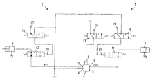
- FIG. 6 shows a circuit diagram of a pressure control device of a pneumatic vehicle brake system, in the form of an electronic brake system EBS, with ABS/ASR and ESP functionalities, as per a further embodiment of the present invention
- FIG. 7 shows a table illustrating various switching states of valves of the pressure control device as per an embodiment of the present invention
- FIG. 8 shows pressure/switching time diagrams which illustrate a changeover of the pressure control device from pressure build-up to pressure dissipation as per an embodiment of the present invention.
- the reference numeral 1 denotes a preferred embodiment of a pressure control device, which comprises a valve unit 2 and an electronics unit, connected mechanically and electrically directly to said valve unit, as a control unit, which in this case is not illustrated for reasons of scale.
- the pressure control device 1 is, in the preferred embodiment, integrated into a compressed-air brake system of a utility vehicle.
- the pressure control device 1 is designed for the wheel-specific, at least brake-slip-dependent control of brake pressures in brake cylinders 3 , 4 of wheels of a driven axle, for example.
- said pressure control device comprises a single relay valve 5 , having a reservoir port 6 which is supplied from a reservoir pressure P 11 , having a deaeration port 7 which is connected to a pressure sink, having a control port 8 , and having two working ports 9 , 10 .
- a first working port 9 is assigned to a first brake cylinder 3 of a wheel of a first vehicle side of the axle
- a second working port 10 of the single relay valve 5 is assigned to a second brake cylinder 4 of the wheel of the second vehicle side of the axle, in order to be able to generate a first brake pressure P 3 in the first brake cylinder 3 and/or a second brake pressure P 4 in the second brake cylinder 4
- each working port 9 , 10 of the relay valve 5 is connected to a 2/2 directional valve 11 , 12 which is preferably indirectly controlled by the control unit and which is assigned to in each case one vehicle side.
- the 2/2 directional valves 11 , 12 in a manner dependent on in this case preferably indirect actuation by the control unit, either produce a connection between the respective working port 9 , 10 of the relay valve 5 and the associated brake cylinder 3 , 4 , or block said connection.
- the control port 8 of the relay valve is connectable either to a brake control pressure P 1 based on a driver braking demand, or to a pressure sink 14 .
- the 3/2 directional solenoid valve 13 is preferably spring-loaded and thereby preloaded, in a deenergized state, into the switching position in which it connects the control port 8 of the relay valve 5 to the brake control pressure P 1 based on a driver braking demand.
- the control port 8 of the relay valve 5 is connected to the pressure sink 14 .
- the brake control pressure P 1 based on a driver braking demand is in this case generated for example by a driver-actuated footbrake module (not shown here).
- the 2/2 directional valves 11 , 12 are particularly preferably pneumatically controllable diaphragm valves which are preferably pneumatically pilot-controlled by way of in each case one 3/2 directional pilot control solenoid valve 15 , 16 , which is electrically controlled by the control unit and assigned to the same vehicle side.
- the 3/2 directional pilot control solenoid valves 15 , 16 are preferably formed such that, in a manner dependent on control by the control unit, they pass through the reservoir pressure P 11 of the pressure reservoir to a control port 17 , 18 of the associated 2/2 directional valve 11 , 12 or, on the hand, connect said control port 17 , 18 to a pressure sink 19 , 20 .
- the 3/2 directional pilot control solenoid valves 15 , 16 are preferably spring-loaded and thereby preloaded, in a deenergized state, into the switching position in which they connect the control port 17 , 18 of the associated 2/2 directional valve 11 , 12 to the pressure sink.
- the control ports 17 , 18 of the 2/2 directional valves 11 , 12 are connected to the pressure sink 19 , 20 .
- control unit is designed such that, by way of control of the 3/2 directional solenoid valve 13 and of the two 3/2 directional pilot control solenoid valves 15 , 16 for the indirect control of the 2/2 directional valves 11 , 12 , wheel-specific brake slip regulation in the context of the typical ABS functions of pressure build-up, pressure holding and pressure dissipation is realized in order to achieve optimum setpoint brake slip.
- the control unit receives information, in a known manner, regarding the wheel rotational speeds of the wheels of the axle from wheel rotational speed sensors (not shown here).
- the central 3/2 directional solenoid valve 13 for the pilot control of the relay valve 5 and the two 3/2 directional pilot control solenoid valves 15 , 16 , are situated in the spring-actuated deenergized basic position shown in FIG. 1 , or are switched into said basic position, such that the 3/2 directional solenoid valve 13 connects the control port 8 of the relay valve 5 to the brake control pressure P 1 based on a driver braking demand. Consequently, from said brake control pressure P 1 , the relay valve 5 modulates a working pressure P 21 and P 22 at its two working ports 9 , 10 .
- the pneumatic control ports 17 , 18 of the two 2/2 directional valves 11 , 12 are in each case connected to the pressure sinks 19 , 20 , such that said 2/2 directional valves are situated in the pass-through position shown in FIG. 1 in order to introduce the working pressure P 21 and P 22 prevailing at the working ports 9 , 10 of the relay valve 5 into the brake cylinders 3 , 4 , from which working pressure the two brake pressures P 3 and P 4 are then obtained.
- the working pressures P 21 and P 22 for the first vehicle side and the second vehicle side are in this case substantially equal.
- the 3/2 directional solenoid valve 13 is initially energized and thereby switched into its deaeration position, in which the control port 8 of the relay valve 5 is connected to the pressure sink 14 . In this way, both working ports 9 , 10 of the relay valve 5 are connected to its pressure sink 7 . Furthermore, on the vehicle side on which no wheel locking occurs, for example at the wheel assigned to the first brake cylinder 3 , the 3/2 directional pilot control solenoid valve 15 is, by energization by the control unit, switched into the position in which the control port 17 of the respective 2/2 directional valve is charged with the reservoir pressure P 11 . In this way, the 2/2 directional valve 11 switches into its blocking position and thereby holds the brake pressure P 3 in the first brake cylinder 3 of the non-locking wheel (pressure holding).
- the 3/2 directional pilot control solenoid valve 16 is not switched over by the control unit, but rather remains in its deenergized basic position, in which the control port 18 of the respective 2/2 directional valve 12 remains switched to the pressure sink 20 .
- the 2/2 directional valve 12 remains in its pass-through position shown in FIG. 1 , whereby the brake pressure P 4 in the brake cylinder 4 of the locking wheel can dissipate via the pressure sink 7 of the relay valve 5 (pressure dissipation).
- the valve device is composed not of a single 3/2 directional solenoid valve but of two 2/2 directional solenoid valves 21 , 22 , wherein a first 2/2 directional solenoid valve 21 , as outlet valve, either connects, in a pressure dissipation position, the control port 8 of the relay valve 5 to a pressure sink 23 , or blocks said connection, as shown.
- a second 2/2 directional solenoid valve 22 either connects, in a pressure build-up position, the control port 8 of the relay valve 5 to the brake control pressure P 1 formed dependently on a driver braking demand, or blocks said connection.
- Both 2/2 directional solenoid valves 21 , 22 are switched in spring-loaded fashion into their basic position shown in FIG. 2 , in which the first 2/2 directional solenoid valve 21 is switched into the blocking position and the second 2/2 directional solenoid valve 22 is switched into the pass-through position.
- the first 2/2 directional solenoid valve 21 is situated in the deenergized blocking position, whereas the second 2/2 directional solenoid valve 22 is situated in the pass-through position. Furthermore, the two 3/2 directional pilot control solenoid valves 15 , 16 are also situated in the spring-actuated deenergized basic position shown in FIG. 2 , such that the other 2/2 directional solenoid valve 22 connects the control port 8 of the relay valve 5 to the brake control pressure P 1 formed dependently on a driver braking demand, as shown in FIG. 2 . As described above, from said brake control pressure P 1 , the relay valve 5 modulates a working pressure P 21 and P 22 at its two working ports 9 , 10 .
- the pneumatic control ports 17 , 18 of the two 2/2 directional valves 11 , 12 are in each case connected to the pressure sinks 19 , 20 , such that said 2/2 directional valves are situated in the pass-through position shown in FIG. 2 in order to introduce the working pressure P 21 and P 22 prevailing at the working ports 9 , 10 of the relay valve 5 into the brake cylinders 3 , 4 as brake pressures P 3 , P 4 .
- the working pressures P 21 and P 22 for the first vehicle side and the second vehicle side are in this case substantially equal.
- the first 2/2 directional solenoid valve 21 as outlet valve, is energized and thereby switched into its pass-through position, in which the control port 8 of the relay valve 5 is connected to the pressure sink 23 , in the pressure dissipation position.
- the second 2/2 directional solenoid valve 22 is also energized, and thereby switched into its blocking position, whereby the control port 8 of the relay valve 5 is decoupled from the brake control pressure P 1 . In this way, both working ports 9 , 10 of the relay valve 5 are connected to its pressure sink 7 .
- the switching of the two 3/2 directional pilot control solenoid valves 15 , 16 is performed as described in the exemplary embodiment above, such that the 2/2 directional valve 11 of the non-locking vehicle side is switched into its blocking position, whereby the first brake pressure P 3 in the first brake cylinder 3 of the non-locking wheel is held (pressure holding).
- the 3/2 directional pilot control solenoid valve 16 is not switched over by the control unit, but rather remains in its deenergized basic position, in which the control port 18 of the respective 2/2 directional valve 12 remains switched to the pressure sink 20 .
- the 2/2 directional valve 12 remains in its pass-through position shown in FIG. 2 , whereby the second brake pressure P 21 or the second brake pressure P 4 in the second brake cylinder 4 of the locking wheel can dissipate via the pressure sink 7 of the relay valve 5 (pressure dissipation).
- FIG. 3 by contrast to the embodiments as per FIG. 1 and FIG. 2 , it is not a reservoir pressure P 11 of a pressure reservoir but the brake control pressure p 1 formed dependently on a driver braking demand that is switched by way of the two 3/2 directional pilot control solenoid valves 15 , 16 to the control ports 17 , 18 of the 2/2 directional valves 11 , 12 .
- the control pressure P 1 based on a driver braking demand decreases, such that the associated 2/2 directional valve 11 or 12 that is closed during the pressure-holding phase can open in order to dissipate the first brake pressure P 3 or the second brake pressure P 4 respectively (pressure dissipation).
- the ABS-capable basic layout as per FIG. 1 to FIG. 3 is, in order to realize drive slip regulation (ASR), supplemented by just one solenoid valve 24 , as per the embodiment of FIG. 4 , which is electrically controlled by the control unit.
- Said solenoid valve 24 then interacts with the valve device 13 such that the control port 8 of the single relay valve 5 is, in a manner dependent on the drive slip of the wheels of the axle, connected to the control pressure P 1 formed dependently on a driver braking demand, to the reservoir pressure P 11 of the pressure reservoir, or to a pressure sink 14 .
- the single additional solenoid valve is preferably a 3/2 directional solenoid valve 24
- the valve device is, analogously to FIG. 1 , likewise formed by a 3/2 directional solenoid valve 13 .
- control unit is designed such that, aside from the ABS functions, wheel-specific drive slip regulation (ASR) is also realized by way of control at least of the additional 3/2 directional solenoid valve 24 .
- Said additional 3/2 directional solenoid valve 24 is, at the control side of the relay valve 5 , connected upstream of the 3/2 directional solenoid valve 13 forming the valve device.
- Said additional 3/2 directional solenoid valve 24 in its spring-loaded, deenergized basic position, connects the control pressure P 1 formed dependently on a driver braking demand through to the 3/2 directional solenoid valve 13 , and in its energized switching position, connects the reservoir pressure P 11 through to the 3/2 directional solenoid valve 13 .
- slip regulation is performed by way of the valves 13 , 15 and 16 in accordance with the wheel drive slip.
- the additional ASR valve 24 connects the control pressure P 1 formed dependently on a driver braking demand through to the 3/2 directional solenoid valve 13 , whereby the control port 8 of the relay valve 5 is, as described with regard to the exemplary embodiment of FIG. 1 , aerated or deaerated in accordance with whether the control pressure P 1 based on a driver braking demand represents a brake-release control pressure or a brake-application control pressure.
- the additional ASR valve 24 is deactivated, the holding valves 11 , 12 automatically open by way of corresponding actuation by the valves 15 , 16 .
- the relay valve 5 In the case of a brake-release control pressure P 1 , that is to say when the footbrake valve is not actuated, the relay valve 5 outputs only a low working pressure P 21 and P 22 at its working ports 9 , 10 respectively, such that both wheel brake cylinders 3 , 4 are released.
- the additional ASR valve 24 connects the reservoir pressure P 11 through to the 3/2 directional solenoid valve 13 , which in this regard is switched into the pass-through position, whereby the control port 8 of the relay valve 5 is aerated with a brake-application control pressure, and said relay valve therefore outputs a brake-application pressure at its working ports 9 , 10 .
- the switching positions of the 3/2 directional pilot control solenoid valves 15 , 16 and of the two 2/2 directional valves 11 , 12 are then as shown in FIG. 4 , such that the wheel brake cylinders 3 , 4 of the axle are, in the presence of inadmissible wheel slip, temporarily applied in the context of wheel slip regulation.
- the control pressure P 1 formed dependently on a driver braking demand increases, such that the associated 2/2 directional valve 11 or 12 that is closed during the pressure-holding phase can open in order to build up brake pressure P 21 or P 22 respectively (pressure build-up).
- valve device comprises not a 3/2 directional solenoid valve 13 but two 2/2 directional solenoid valves 21 , 22 as per FIG. 3 and FIG. 6
- one 2/2 directional solenoid valve 21 is preferably an outlet valve which either connects the control port 8 of the relay valve 5 to its pressure sink 23 , or blocks said connection.
- the second 2/2 directional solenoid valve 22 is in particular a valve that can also be utilized as a backup valve of an EBS, which valve either connects the control port 8 of the relay valve 5 to the control pressure p 1 formed dependently on a driver braking demand, or blocks said connection.
- the single additional solenoid valve provided for realizing the drive slip regulation of the axle is, in the embodiment of FIG. 6 , preferably an inlet valve 26 in the form of a 2/2 directional solenoid valve.
- the inlet valve 26 , the first 2/2 directional solenoid valve 21 as outlet valve and the backup valve 22 then form not only a brake slip regulation (ABS) arrangement and a drive slip regulation (ASR) arrangement but also an electronically regulated brake system (EBS) with primary electropneumatic brake circuit and secondary pneumatic brake circuit, if it is additionally the case, for example, that a working port 9 , 10 of the single relay valve 5 is connected in pressure-conducting fashion to a pressure sensor 27 .
- ABS brake slip regulation
- ASR drive slip regulation
- EBS electronically regulated brake system
- control unit is designed such that, in addition to implementing the ABS and ASR functions, it also, by control of the inlet valve 26 and of the first 2/2 directional solenoid valve 21 as outlet valve, adapts the actual brake pressure measured by the pressure sensor 27 to a setpoint brake pressure formed dependently on a driver braking demand, in the context of brake pressure regulation.
- the mode of operation of the EBS is then as follows:
- the first 2/2 directional solenoid valve 21 as outlet valve, remains in its spring-loaded blocking position, whereas the inlet valve 26 is switched into the pass-through position in order to aerate the control port 8 of the relay valve 5 with reservoir pressure.
- This has the effect that working pressure P 21 and P 22 prevails at the two working ports 9 , 10 of the relay valve 5 , which are connected through to the wheel brake cylinders 3 , 4 by way of the two 2/2 directional valves 11 , 12 switched into the pass-through position.
- the backup valve 22 in this case remains in its energized blocking position, such that the control pressure P 1 formed dependently on a driver braking demand, such as prevails at said backup valve, cannot be connected through to the control port 8 of the relay valve 5 .
- the solenoid valves 15 , 16 , 21 , 22 , 26 can no longer be energized.
- the inlet valve 26 switches back into its deenergized and spring-loaded blocking position, such that reservoir pressure no longer passes to the control port 8 of the relay valve 5 .
- the first 2/2 directional solenoid valve 21 as outlet valve, likewise remains in the blocking position.
- the control port 8 of the relay valve 8 is charged with the control pressure P 1 formed dependently on a driver braking demand, as generated by the footbrake valve, for the purposes of applying the wheel brake cylinders 3 , 4 .
- ABS and ASR functions then proceed as in the embodiments described above, that is to say the control port 8 of the relay valve 5 is, in a functionally dependent manner, connected by way of the inlet valve 26 to the reservoir pressure P 11 , by way of the backup valve 22 to the control pressure P 1 based on a driver braking demand or is connected to the pressure sink 23 of the outlet valve 21 by way of the first 2/2 directional solenoid valve 21 as outlet valve.
- a further pressure sensor 28 is provided for measuring the brake control pressure P 1 formed dependently on a driver braking demand. Then, if in each case one pressure control device 1 as per FIG. 6 is provided for each axle, for example for a front axle and for a rear axle, it is possible for a driving dynamics regulation (ESP) arrangement to be realized.
- ESP driving dynamics regulation
- control unit is designed such that, in the case of a braking operation initiated by the driving dynamics regulation (ESP) arrangement, said control unit controls the first 2/2 directional solenoid valve 21 as outlet valve, the backup valve 22 and the inlet valve 26 such that the control port 8 of the relay valve 5 is charged with the reservoir pressure P 11 of the pressure reservoir in a manner dependent on the yaw rate of the vehicle.
- ESP driving dynamics regulation
- the 3/2 directional pilot control solenoid valves 15 , 16 are actuated by the control unit such that, for example, the 2/2 directional valve 11 assigned to the first brake cylinder 3 of the first vehicle side is switched into the pass-through position in order to aerate said first brake cylinder 3 , and the 2/2 directional valve 12 assigned to the second brake cylinder 4 of the second vehicle side is switched into the blocking position, in order to shut off said second brake cylinder 4 with respect to the pressure build-up.
- a pressure control device 1 as described above, and a method as described above for controlling a pressure control device 1 of said type, are known from German patent document no. DE 10 2010 010 606 A1, as cited in the introduction.
- the present invention is based on the features of the pressure control device 1 known from said document, and on the control thereof, and also encompasses said features and control.
- FIG. 7 illustrates a table in which various switching states of valves of the pressure control device are shown.
- the brake pressure P 4 in the second brake cylinder 4 and the brake pressure P 3 in the first brake cylinder 3 are initially held.
- the 3/2 directional solenoid valve is switched for example into the pressure build-up position and the two 2/2 directional valves 11 , 12 are switched into the blocking position. Said holding of the pressures by blocking of the two 2/2 directional valves 11 , 12 is performed for example only over a time period required by the relay valve 5 , owing to its inertia, to bring the working pressures P 21 and P 22 to a value higher than the brake pressures P 3 and P 4 in the two brake cylinders.
- one of the two 2/2 directional valves 11 , 12 , or else both 2/2 directional valves 11 , 12 is or are switched into the pass-through position in order to increase one of the pressures P 3 or P 4 or in order to increase both pressures P 3 and P 4 .
- “forced holding” is realized here.
- the pressure control device 1 is in a type of “build-up priority” state, because, by way of the switching of the 3/2 directional valve 13 into the pressure build-up position, preparation has been performed for a pressure build-up in one or both brake cylinders 3 , 4 .
- the brake pressure P 4 in the second brake cylinder 4 it is the intention for the brake pressure P 4 in the second brake cylinder 4 to be held and for the brake pressure P 3 in the first brake cylinder 3 to be decreased.
- the 3/2 directional solenoid valve is switched into the pressure dissipation position, the 2/2 directional valve 11 is switched into the pass-through position, and the 2/2 directional valve 12 is switched into the blocking position.
- the brake pressure P 4 in the second brake cylinder 4 and the brake pressure P 3 in the first brake cylinder 3 are initially held.
- the 3/2 directional solenoid valve is switched for example into the pressure dissipation position and the two 2/2 directional valves 11 , 12 are switched into the blocking position. Said holding of the pressures by blocking of the two 2/2 directional valves 11 , 12 is performed for example only over a time period required by the relay valve 5 , owing to its inertia, to bring the working pressures P 21 and P 22 to a value lower than the brake pressures P 3 and P 4 in the two brake cylinders 3 , 4 .
- one of the two 2/2 directional valves 11 , 12 , or else both 2/2 directional valves 11 , 12 is or are switched into the pass-through position in order to reduce one of the pressures P 3 or P 4 or in order to reduce both pressures P 3 and P 4 .
- “forced holding” is likewise realized here.
- the pressure control device 1 is in a type of “dissipation priority” state, because, by way of the switching of the 3/2 directional valve 13 into the pressure dissipation position, preparation has been performed for a pressure dissipation in one or both brake cylinders 3 , 4 .
- FIG. 8 illustrates the profile of the working pressure P 22 at the working port 9 of the relay valve 5 and of the pressure P 3 in the brake cylinder 3 , and the switching profile of the 3/2 directional valve 13 and of the 2/2 directional valve 13 , over the time t in an operating situation in which, for example owing to excessive brake slip, in the context of an ABS arrangement, a pressure dissipation has occurred as a starting situation and, after a reduction of the brake slip to an admissible brake slip, the brake pressure is being built up again. Thereafter, owing to assumed re-occurrence of excessive brake slip, another change from pressure build-up to pressure dissipation is necessary.
- the 3/2 directional solenoid valve 13 is, at the time t 1 , switched into its pressure build-up position (symbolized in FIG. 8 by a low bar depicted using a solid line) (change from pressure dissipation to pressure build-up).
- an approximately constant brake pressure P 3 greater than 0 prevails in the brake cylinder.
- the working pressure P 22 however rises only slowly owing to the inertia of the relay valve 5 , even though the control port 8 of the relay valve has already been aerated at the time t 1 by way of the 3/2 directional solenoid valve 13 switched into the pressure build-up position.
- the 2/2 directional valve 11 assigned to the brake cylinder 3 still remains in the blocking position over a time period a, this being realized by virtue of the 3/2 directional pilot control solenoid valve 15 , which effects pilot control of the 2/2 directional valve 11 , remaining activated.
- the 3/2 directional pilot control solenoid valve 15 is actuated in pulsed fashion in order to switch the 2/2 directional valve 11 briefly into the pass-through position and then into the blocking position again, which results in a step-like increase of the pressure p 3 in the brake cylinder 3 .
- the first actuation pulse of the 3/2 directional pilot control solenoid valve 15 is followed by a second actuation pulse, whereby, however, the 2/2 directional valve 11 is switched into the pass-through position immediately without a waiting time, because now the condition P 22 >P 3 is immediately satisfied.
- the 3/2 directional solenoid valve 13 is switched from the pressure build-up position into its pressure dissipation position.
- a pressure dissipation of the working pressure P 22 at the working port 9 takes place, in turn, with a time delay, wherein it is only after expiry of a time period b at the time t 4 that the condition P 22 ⁇ P 3 is satisfied, and therefore only at the time t 4 that the 3/2 directional pilot control solenoid valve 15 is actuated in pulsed fashion in order to switch the 2/2 directional valve 11 briefly into the pass-through position and then into the blocking position again, which results in a step-like reduction of the pressure P 3 in the brake cylinder 3 .
- the 2/2 directional valve 11 is switched from its blocking position into the pass-through position preferably in pulsed fashion, wherein the time segments for the pass-through phases and the blocking phases are dependent on the speed with which the pressure P 3 in the brake cylinder 3 is to be increased or reduced.
- the pulsed control of the 2/2 directional valve 11 is in this case performed preferably pneumatically by way of the 3/2 directional pilot control solenoid valve 15 , which is actuated in correspondingly electrically pulsed fashion by the control unit.
- the 2/2 directional valve 11 it would however also be possible for the 2/2 directional valve 11 to be a solenoid valve, and to then be actuated directly by the control unit.
- the sequence of changes between pressure build-up and pressure dissipation phases described here by way of example only for the first brake cylinder 3 may self-evidently also be implemented in the same or similar fashion at the second brake cylinder 4 , or at both brake cylinders 3 and 4 in parallel. Even though the sequence has been presented here by way of example on the basis of ABS regulation, it may self-evidently also be implemented in the context of any desired regulation, in particular in accordance with ASR or ESP regulation. It is also possible, for the above-described sequence, for use to be made of the two 2/2 directional solenoid valves as per FIG. 2 or FIG. 6 instead of the single 3/2 directional solenoid valve 13 .
- the pressures P 3 , P 4 in the brake cylinders 3 , 4 and/or the working pressure P 21 , P 22 at the respective working port 9 , 10 of the relay valve 5 are measured by way of a pressure sensor (not shown here) or to be estimated from other variables by way of an estimation algorithm.
- a pressure build-up or a pressure dissipation at the first brake cylinder 3 is firstly fully completed before a pressure build-up or a pressure dissipation at the second brake cylinder 4 is commenced, and vice versa.
- the 3/2 directional solenoid valve 13 or the two 2/2 directional solenoid valves as per FIG. 2 or FIG. 6 are actuated in pulse-width-modulated fashion for the pressure build-up or pressure dissipation. This yields fast switching between the pressure build-up position and the pressure dissipation position, whereby a suspension pressure is generated in the control chamber, which is connected to the control port 8 , of the relay valve 5 , which improves the reaction time of the relay valve 5 and reduces the inertia thereof to certain extent.
- the 3/2 directional solenoid valve 13 may, in a basic position in which no braking demand exists, be actuated into the pressure dissipation position or into the pressure build-up position.
- FIGS. 7 and 8 The method described in FIGS. 7 and 8 and above is provided for the control of a pressure control device 1 according to the embodiments as per FIGS. 1 to 6 .
Landscapes
- Engineering & Computer Science (AREA)
- Transportation (AREA)
- Mechanical Engineering (AREA)
- Physics & Mathematics (AREA)
- Fluid Mechanics (AREA)
- Electromagnetism (AREA)
- Chemical & Material Sciences (AREA)
- Combustion & Propulsion (AREA)
- Regulating Braking Force (AREA)
- Braking Systems And Boosters (AREA)
Applications Claiming Priority (4)
| Application Number | Priority Date | Filing Date | Title |
|---|---|---|---|
| DE102013016877.5 | 2013-10-11 | ||
| DE102013016877 | 2013-10-11 | ||
| DE102013016877.5A DE102013016877B3 (de) | 2013-10-11 | 2013-10-11 | Verfahren zum Steuern einer Drucksteuervorrichtung einer Druckmittel-Bremsanlage eines Fahrzeugs |
| PCT/EP2014/071615 WO2015052271A1 (fr) | 2013-10-11 | 2014-10-09 | Procédé de commande d'un dispositif de commande de pression d'un système de freinage à fluide sous pression d'un véhicule automobile |
Related Parent Applications (1)
| Application Number | Title | Priority Date | Filing Date |
|---|---|---|---|
| PCT/EP2014/071615 Continuation WO2015052271A1 (fr) | 2013-10-11 | 2014-10-09 | Procédé de commande d'un dispositif de commande de pression d'un système de freinage à fluide sous pression d'un véhicule automobile |
Publications (2)
| Publication Number | Publication Date |
|---|---|
| US20160304070A1 US20160304070A1 (en) | 2016-10-20 |
| US9944261B2 true US9944261B2 (en) | 2018-04-17 |
Family
ID=51567766
Family Applications (1)
| Application Number | Title | Priority Date | Filing Date |
|---|---|---|---|
| US15/095,762 Expired - Fee Related US9944261B2 (en) | 2013-10-11 | 2016-04-11 | Method for controlling a pressure control device of a pressure-medium brake system of a vehicle |
Country Status (7)
| Country | Link |
|---|---|
| US (1) | US9944261B2 (fr) |
| EP (1) | EP3055175B1 (fr) |
| CN (1) | CN105612088B (fr) |
| BR (1) | BR112016007678A2 (fr) |
| DE (1) | DE102013016877B3 (fr) |
| RU (1) | RU2640166C2 (fr) |
| WO (1) | WO2015052271A1 (fr) |
Families Citing this family (5)
| Publication number | Priority date | Publication date | Assignee | Title |
|---|---|---|---|---|
| DE102014017683A1 (de) * | 2014-11-28 | 2016-06-02 | Wabco Gmbh | Verfahren zum Steuern eines pneumatischen Bremssystems und derartiges pneumatisches Bremssystem für ein Fahrzeug |
| DE102015014205A1 (de) * | 2015-11-04 | 2017-05-04 | Wabco Gmbh | Hydraulische Bremsanlage |
| DE102015015472A1 (de) * | 2015-11-28 | 2017-06-01 | Wabco Gmbh | Hydraulische Bremsanlage |
| DE102016004489A1 (de) | 2016-04-18 | 2017-10-19 | Wabco Gmbh | Fahrer-Bremsventil, Druckluft-Bremssystem mit dem Fahrer-Bremsventil und Verfahren zur Herstellung des Fahrer-Bremsventils |
| DE102019103901A1 (de) * | 2019-02-15 | 2020-08-20 | Wabco Gmbh | Feststellbremsanordnung mit radindividueller ABS-Steuerung |
Citations (13)
| Publication number | Priority date | Publication date | Assignee | Title |
|---|---|---|---|---|
| US4238955A (en) | 1978-03-25 | 1980-12-16 | Wabco Fahrzeugbremsen Gmbh | Tire-pressure monitoring device |
| US4805105A (en) * | 1985-12-06 | 1989-02-14 | Robert Bosch Gmbh | Method and system for electrically controlling braking of a vehicle |
| US5718486A (en) * | 1993-12-17 | 1998-02-17 | Knorr-Bremse Systeme Fur Nutzfahrzeuge Gmbh | Electropneumatic brakes system for motor vehicles |
| US7020551B2 (en) * | 2003-12-23 | 2006-03-28 | Bendix Commercial Vehicle Systems Llc | Roll stability control system |
| US20060152075A1 (en) * | 2002-08-12 | 2006-07-13 | Knorr-Bremse Systeme Fuer Nutzfahrzeuge Gmbh | Pressure regulator module for a motor vehicle pneumatic braking system |
| US20070236084A1 (en) * | 2004-07-21 | 2007-10-11 | Dieter Frank | Brake-Pressure Modulator Pilot Unit |
| US20090184568A1 (en) * | 2005-12-16 | 2009-07-23 | Uwe Bensch | Electro-Pneumatic Brake Control Device |
| US20110144855A1 (en) * | 2008-06-20 | 2011-06-16 | Michael Herges | Monitoring device for monitoring systems of a vehicle |
| US20110193407A1 (en) * | 2010-02-08 | 2011-08-11 | Dirk Wohltmann | Vehicle braking system |
| DE102010010606A1 (de) | 2010-03-08 | 2011-09-08 | Knorr-Bremse Systeme für Nutzfahrzeuge GmbH | Modular aufgebaute Drucksteuervorrichtung einer Druckmittel-Bremsanlage eines Fahrzeugs |
| US20140319904A1 (en) * | 2013-04-26 | 2014-10-30 | Mitsubishi Electric Corporation | Brake control device and brake control method |
| US9002610B2 (en) * | 2011-12-09 | 2015-04-07 | Bendix Commercial Vehicle Systems, Llc | Relay valve control arrangement to provide variable response timing on full applications |
| US9505386B2 (en) * | 2011-02-24 | 2016-11-29 | Knorr-Bremse Systeme Fuer Nutzfahrzeuge Gmbh | Traction-slip controlled brake system of a motor vehicle approaching stops |
Family Cites Families (1)
| Publication number | Priority date | Publication date | Assignee | Title |
|---|---|---|---|---|
| JP4535103B2 (ja) * | 2007-09-04 | 2010-09-01 | トヨタ自動車株式会社 | ブレーキ制御装置 |
-
2013
- 2013-10-11 DE DE102013016877.5A patent/DE102013016877B3/de not_active Expired - Fee Related
-
2014
- 2014-10-09 WO PCT/EP2014/071615 patent/WO2015052271A1/fr active Application Filing
- 2014-10-09 EP EP14783802.3A patent/EP3055175B1/fr active Active
- 2014-10-09 CN CN201480055861.8A patent/CN105612088B/zh not_active Expired - Fee Related
- 2014-10-09 RU RU2016118149A patent/RU2640166C2/ru not_active IP Right Cessation
- 2014-10-09 BR BR112016007678A patent/BR112016007678A2/pt not_active IP Right Cessation
-
2016
- 2016-04-11 US US15/095,762 patent/US9944261B2/en not_active Expired - Fee Related
Patent Citations (15)
| Publication number | Priority date | Publication date | Assignee | Title |
|---|---|---|---|---|
| US4238955A (en) | 1978-03-25 | 1980-12-16 | Wabco Fahrzeugbremsen Gmbh | Tire-pressure monitoring device |
| SU965346A3 (ru) | 1978-03-25 | 1982-10-07 | Вабко Фарцойгбремзен Гмбх (Фирма) | Устройство дл контролировани состо ни колеса транспортного средства |
| US4805105A (en) * | 1985-12-06 | 1989-02-14 | Robert Bosch Gmbh | Method and system for electrically controlling braking of a vehicle |
| US5718486A (en) * | 1993-12-17 | 1998-02-17 | Knorr-Bremse Systeme Fur Nutzfahrzeuge Gmbh | Electropneumatic brakes system for motor vehicles |
| US20060152075A1 (en) * | 2002-08-12 | 2006-07-13 | Knorr-Bremse Systeme Fuer Nutzfahrzeuge Gmbh | Pressure regulator module for a motor vehicle pneumatic braking system |
| US7020551B2 (en) * | 2003-12-23 | 2006-03-28 | Bendix Commercial Vehicle Systems Llc | Roll stability control system |
| US20070236084A1 (en) * | 2004-07-21 | 2007-10-11 | Dieter Frank | Brake-Pressure Modulator Pilot Unit |
| US20090184568A1 (en) * | 2005-12-16 | 2009-07-23 | Uwe Bensch | Electro-Pneumatic Brake Control Device |
| US20110144855A1 (en) * | 2008-06-20 | 2011-06-16 | Michael Herges | Monitoring device for monitoring systems of a vehicle |
| US20110193407A1 (en) * | 2010-02-08 | 2011-08-11 | Dirk Wohltmann | Vehicle braking system |
| DE102010010606A1 (de) | 2010-03-08 | 2011-09-08 | Knorr-Bremse Systeme für Nutzfahrzeuge GmbH | Modular aufgebaute Drucksteuervorrichtung einer Druckmittel-Bremsanlage eines Fahrzeugs |
| US20130073165A1 (en) * | 2010-03-08 | 2013-03-21 | Friedbert Roether | Modularly designed pressure control device of a fluid pressure brake system of a vehicle |
| US9505386B2 (en) * | 2011-02-24 | 2016-11-29 | Knorr-Bremse Systeme Fuer Nutzfahrzeuge Gmbh | Traction-slip controlled brake system of a motor vehicle approaching stops |
| US9002610B2 (en) * | 2011-12-09 | 2015-04-07 | Bendix Commercial Vehicle Systems, Llc | Relay valve control arrangement to provide variable response timing on full applications |
| US20140319904A1 (en) * | 2013-04-26 | 2014-10-30 | Mitsubishi Electric Corporation | Brake control device and brake control method |
Non-Patent Citations (4)
| Title |
|---|
| German-language Written Opinion (PCT/ISA/237) issued in PCT Application No. PCT/EP2014/071615 dated Jan. 20, 2015 (ten (10) pages). |
| International Preliminary Report on Patentability (PCT/IB/326, PCT/IB/338 & PCT/IB/373) issued in PCT Application No. PCT/EP2014/071615 dated Apr. 21, 2016, including English translation of document C2 (German-language Written Opinion (PCT/ISA/237)) previously filed on Apr. 11, 2016 (17 pages). |
| International Search Report (PCT/ISA/210) issued in PCT Application No. PCT/EP2014/071615 dated Jan. 20, 2015 with English-language translation (four (4) pages). |
| Russian Office Action issued in counterpart Russian Application No. 2016118149/11(028491) dated Jul. 6, 2017 with unverified English translation (13 pages). |
Also Published As
| Publication number | Publication date |
|---|---|
| CN105612088B (zh) | 2017-12-15 |
| RU2016118149A (ru) | 2017-11-16 |
| DE102013016877B3 (de) | 2014-10-09 |
| EP3055175A1 (fr) | 2016-08-17 |
| RU2640166C2 (ru) | 2017-12-26 |
| BR112016007678A2 (pt) | 2017-08-01 |
| WO2015052271A1 (fr) | 2015-04-16 |
| CN105612088A (zh) | 2016-05-25 |
| US20160304070A1 (en) | 2016-10-20 |
| EP3055175B1 (fr) | 2019-01-02 |
Similar Documents
| Publication | Publication Date | Title |
|---|---|---|
| US8918262B2 (en) | Modularly designed pressure control device of a fluid pressure brake system of a vehicle | |
| US9944261B2 (en) | Method for controlling a pressure control device of a pressure-medium brake system of a vehicle | |
| US11052892B2 (en) | Electronically controllable pneumatic brake system in a utility vehicle and method for electronically controlling a pneumatic brake system | |
| US9896076B2 (en) | Traction-slip controlled brake system of a motor vehicle approaching stops | |
| US11034341B2 (en) | Electronically controllable pneumatic brake system in a utility vehicle and method for electronically controlling a pneumatic brake system in a utility vehicle | |
| US10399550B2 (en) | Method for controlling a motor vehicle service brake device and service brake valve device for said type of service brake device | |
| US9315179B2 (en) | Method for controlling a brake system of a vehicle with an electronically rgulated rear-axle brake circuit and an pneumatically controlled front-axle brake circuit | |
| KR101964536B1 (ko) | 브레이크 시스템을 동작시키는 방법, 및 그 방법이 실행되는 브레이크 시스템 | |
| CN111247044B (zh) | 压缩空气制动设施的车轴阀模块和继动阀模块 | |
| US20220055594A1 (en) | Method for adjusting brake pressures of a vehicle via control of a pressure control valve, brake system for carrying out the method and motor vehicle | |
| CN108016419B (zh) | 能够电子滑动调节的制动设备 | |
| US9776611B2 (en) | Method for controlling a pneumatic brake system and a pneumatic brake system for a vehicle | |
| CN110023159B (zh) | 用于商用车的制动设备的空气处理单元和空气处理单元的运行方法 | |
| US8870300B2 (en) | Method for actuating a hydraulic vehicle brake system | |
| US20210122350A1 (en) | Heavy duty vehicle redundant braking system | |
| US20190126899A1 (en) | Electronically pressure-controllable vehicle braking system and method for controlling an electronically pressure-controllable vehicle braking system | |
| US11453373B2 (en) | Brake control device for vehicle | |
| CN113365889B (zh) | 具有针对单独车轮的abs控制部的驻车制动器设施 | |
| US11479226B2 (en) | Parking brake device for a motor vehicle | |
| US11702054B2 (en) | Redundant braking unit for a braking system and system using same | |
| CN108116387B (zh) | 以电子方式能滑动调节的制动设备 | |
| WO2016084838A1 (fr) | Dispositif de freinage pour véhicule | |
| EP1439104B1 (fr) | Dispositif de commande des freins | |
| JP2007516126A (ja) | 多用途車用のブレーキ系 |
Legal Events
| Date | Code | Title | Description |
|---|---|---|---|
| AS | Assignment |
Owner name: KNORR-BREMSE SYSTEME FUER NUTZFAHRZEUGE GMBH, GERM Free format text: ASSIGNMENT OF ASSIGNORS INTEREST;ASSIGNORS:WIEDER, GERHARD;SCHAEFERS, ANDREAS;HOLOBRADI, PETER;SIGNING DATES FROM 20160512 TO 20160530;REEL/FRAME:039064/0258 |
|
| STCF | Information on status: patent grant |
Free format text: PATENTED CASE |
|
| FEPP | Fee payment procedure |
Free format text: MAINTENANCE FEE REMINDER MAILED (ORIGINAL EVENT CODE: REM.); ENTITY STATUS OF PATENT OWNER: LARGE ENTITY |
|
| LAPS | Lapse for failure to pay maintenance fees |
Free format text: PATENT EXPIRED FOR FAILURE TO PAY MAINTENANCE FEES (ORIGINAL EVENT CODE: EXP.); ENTITY STATUS OF PATENT OWNER: LARGE ENTITY |
|
| STCH | Information on status: patent discontinuation |
Free format text: PATENT EXPIRED DUE TO NONPAYMENT OF MAINTENANCE FEES UNDER 37 CFR 1.362 |
|
| FP | Lapsed due to failure to pay maintenance fee |
Effective date: 20220417 |