US9910207B2 - Polarization recovery in a directional display device - Google Patents
Polarization recovery in a directional display device Download PDFInfo
- Publication number
- US9910207B2 US9910207B2 US14/993,042 US201614993042A US9910207B2 US 9910207 B2 US9910207 B2 US 9910207B2 US 201614993042 A US201614993042 A US 201614993042A US 9910207 B2 US9910207 B2 US 9910207B2
- Authority
- US
- United States
- Prior art keywords
- light
- waveguide
- polarization
- reflector
- directional
- Prior art date
- Legal status (The legal status is an assumption and is not a legal conclusion. Google has not performed a legal analysis and makes no representation as to the accuracy of the status listed.)
- Active, expires
Links
Images


Classifications
-
- G—PHYSICS
- G02—OPTICS
- G02B—OPTICAL ELEMENTS, SYSTEMS OR APPARATUS
- G02B6/00—Light guides; Structural details of arrangements comprising light guides and other optical elements, e.g. couplings
- G02B6/0001—Light guides; Structural details of arrangements comprising light guides and other optical elements, e.g. couplings specially adapted for lighting devices or systems
- G02B6/0011—Light guides; Structural details of arrangements comprising light guides and other optical elements, e.g. couplings specially adapted for lighting devices or systems the light guides being planar or of plate-like form
- G02B6/0033—Means for improving the coupling-out of light from the light guide
- G02B6/0035—Means for improving the coupling-out of light from the light guide provided on the surface of the light guide or in the bulk of it
- G02B6/0045—Means for improving the coupling-out of light from the light guide provided on the surface of the light guide or in the bulk of it by shaping at least a portion of the light guide
- G02B6/0046—Tapered light guide, e.g. wedge-shaped light guide
- G02B6/0048—Tapered light guide, e.g. wedge-shaped light guide with stepwise taper
-
- F—MECHANICAL ENGINEERING; LIGHTING; HEATING; WEAPONS; BLASTING
- F21—LIGHTING
- F21V—FUNCTIONAL FEATURES OR DETAILS OF LIGHTING DEVICES OR SYSTEMS THEREOF; STRUCTURAL COMBINATIONS OF LIGHTING DEVICES WITH OTHER ARTICLES, NOT OTHERWISE PROVIDED FOR
- F21V13/00—Producing particular characteristics or distribution of the light emitted by means of a combination of elements specified in two or more of main groups F21V1/00 - F21V11/00
- F21V13/12—Combinations of only three kinds of elements
-
- G02B27/225—
-
- G—PHYSICS
- G02—OPTICS
- G02B—OPTICAL ELEMENTS, SYSTEMS OR APPARATUS
- G02B30/00—Optical systems or apparatus for producing three-dimensional [3D] effects, e.g. stereoscopic images
- G02B30/20—Optical systems or apparatus for producing three-dimensional [3D] effects, e.g. stereoscopic images by providing first and second parallax images to an observer's left and right eyes
- G02B30/26—Optical systems or apparatus for producing three-dimensional [3D] effects, e.g. stereoscopic images by providing first and second parallax images to an observer's left and right eyes of the autostereoscopic type
- G02B30/33—Optical systems or apparatus for producing three-dimensional [3D] effects, e.g. stereoscopic images by providing first and second parallax images to an observer's left and right eyes of the autostereoscopic type involving directional light or back-light sources
-
- G—PHYSICS
- G02—OPTICS
- G02B—OPTICAL ELEMENTS, SYSTEMS OR APPARATUS
- G02B6/00—Light guides; Structural details of arrangements comprising light guides and other optical elements, e.g. couplings
- G02B6/0001—Light guides; Structural details of arrangements comprising light guides and other optical elements, e.g. couplings specially adapted for lighting devices or systems
- G02B6/0011—Light guides; Structural details of arrangements comprising light guides and other optical elements, e.g. couplings specially adapted for lighting devices or systems the light guides being planar or of plate-like form
- G02B6/0033—Means for improving the coupling-out of light from the light guide
- G02B6/0056—Means for improving the coupling-out of light from the light guide for producing polarisation effects, e.g. by a surface with polarizing properties or by an additional polarizing elements
-
- G—PHYSICS
- G02—OPTICS
- G02B—OPTICAL ELEMENTS, SYSTEMS OR APPARATUS
- G02B6/00—Light guides; Structural details of arrangements comprising light guides and other optical elements, e.g. couplings
- G02B6/0001—Light guides; Structural details of arrangements comprising light guides and other optical elements, e.g. couplings specially adapted for lighting devices or systems
- G02B6/0011—Light guides; Structural details of arrangements comprising light guides and other optical elements, e.g. couplings specially adapted for lighting devices or systems the light guides being planar or of plate-like form
- G02B6/0066—Light guides; Structural details of arrangements comprising light guides and other optical elements, e.g. couplings specially adapted for lighting devices or systems the light guides being planar or of plate-like form characterised by the light source being coupled to the light guide
- G02B6/0068—Arrangements of plural sources, e.g. multi-colour light sources
-
- G—PHYSICS
- G02—OPTICS
- G02F—OPTICAL DEVICES OR ARRANGEMENTS FOR THE CONTROL OF LIGHT BY MODIFICATION OF THE OPTICAL PROPERTIES OF THE MEDIA OF THE ELEMENTS INVOLVED THEREIN; NON-LINEAR OPTICS; FREQUENCY-CHANGING OF LIGHT; OPTICAL LOGIC ELEMENTS; OPTICAL ANALOGUE/DIGITAL CONVERTERS
- G02F1/00—Devices or arrangements for the control of the intensity, colour, phase, polarisation or direction of light arriving from an independent light source, e.g. switching, gating or modulating; Non-linear optics
- G02F1/01—Devices or arrangements for the control of the intensity, colour, phase, polarisation or direction of light arriving from an independent light source, e.g. switching, gating or modulating; Non-linear optics for the control of the intensity, phase, polarisation or colour
- G02F1/13—Devices or arrangements for the control of the intensity, colour, phase, polarisation or direction of light arriving from an independent light source, e.g. switching, gating or modulating; Non-linear optics for the control of the intensity, phase, polarisation or colour based on liquid crystals, e.g. single liquid crystal display cells
- G02F1/133—Constructional arrangements; Operation of liquid crystal cells; Circuit arrangements
- G02F1/1333—Constructional arrangements; Manufacturing methods
- G02F1/1335—Structural association of cells with optical devices, e.g. polarisers or reflectors
-
- G02B27/2264—
-
- G—PHYSICS
- G02—OPTICS
- G02B—OPTICAL ELEMENTS, SYSTEMS OR APPARATUS
- G02B30/00—Optical systems or apparatus for producing three-dimensional [3D] effects, e.g. stereoscopic images
- G02B30/20—Optical systems or apparatus for producing three-dimensional [3D] effects, e.g. stereoscopic images by providing first and second parallax images to an observer's left and right eyes
- G02B30/22—Optical systems or apparatus for producing three-dimensional [3D] effects, e.g. stereoscopic images by providing first and second parallax images to an observer's left and right eyes of the stereoscopic type
- G02B30/24—Optical systems or apparatus for producing three-dimensional [3D] effects, e.g. stereoscopic images by providing first and second parallax images to an observer's left and right eyes of the stereoscopic type involving temporal multiplexing, e.g. using sequentially activated left and right shutters
-
- G—PHYSICS
- G02—OPTICS
- G02B—OPTICAL ELEMENTS, SYSTEMS OR APPARATUS
- G02B6/00—Light guides; Structural details of arrangements comprising light guides and other optical elements, e.g. couplings
- G02B6/0001—Light guides; Structural details of arrangements comprising light guides and other optical elements, e.g. couplings specially adapted for lighting devices or systems
- G02B6/0011—Light guides; Structural details of arrangements comprising light guides and other optical elements, e.g. couplings specially adapted for lighting devices or systems the light guides being planar or of plate-like form
- G02B6/0013—Means for improving the coupling-in of light from the light source into the light guide
- G02B6/0015—Means for improving the coupling-in of light from the light source into the light guide provided on the surface of the light guide or in the bulk of it
- G02B6/0016—Grooves, prisms, gratings, scattering particles or rough surfaces
-
- G—PHYSICS
- G02—OPTICS
- G02B—OPTICAL ELEMENTS, SYSTEMS OR APPARATUS
- G02B6/00—Light guides; Structural details of arrangements comprising light guides and other optical elements, e.g. couplings
- G02B6/0001—Light guides; Structural details of arrangements comprising light guides and other optical elements, e.g. couplings specially adapted for lighting devices or systems
- G02B6/0011—Light guides; Structural details of arrangements comprising light guides and other optical elements, e.g. couplings specially adapted for lighting devices or systems the light guides being planar or of plate-like form
- G02B6/0013—Means for improving the coupling-in of light from the light source into the light guide
- G02B6/0023—Means for improving the coupling-in of light from the light source into the light guide provided by one optical element, or plurality thereof, placed between the light guide and the light source, or around the light source
- G02B6/0028—Light guide, e.g. taper
-
- G—PHYSICS
- G02—OPTICS
- G02B—OPTICAL ELEMENTS, SYSTEMS OR APPARATUS
- G02B6/00—Light guides; Structural details of arrangements comprising light guides and other optical elements, e.g. couplings
- G02B6/0001—Light guides; Structural details of arrangements comprising light guides and other optical elements, e.g. couplings specially adapted for lighting devices or systems
- G02B6/0011—Light guides; Structural details of arrangements comprising light guides and other optical elements, e.g. couplings specially adapted for lighting devices or systems the light guides being planar or of plate-like form
- G02B6/0013—Means for improving the coupling-in of light from the light source into the light guide
- G02B6/0023—Means for improving the coupling-in of light from the light source into the light guide provided by one optical element, or plurality thereof, placed between the light guide and the light source, or around the light source
- G02B6/003—Lens or lenticular sheet or layer
-
- G—PHYSICS
- G02—OPTICS
- G02B—OPTICAL ELEMENTS, SYSTEMS OR APPARATUS
- G02B6/00—Light guides; Structural details of arrangements comprising light guides and other optical elements, e.g. couplings
- G02B6/0001—Light guides; Structural details of arrangements comprising light guides and other optical elements, e.g. couplings specially adapted for lighting devices or systems
- G02B6/0011—Light guides; Structural details of arrangements comprising light guides and other optical elements, e.g. couplings specially adapted for lighting devices or systems the light guides being planar or of plate-like form
- G02B6/0013—Means for improving the coupling-in of light from the light source into the light guide
- G02B6/0023—Means for improving the coupling-in of light from the light source into the light guide provided by one optical element, or plurality thereof, placed between the light guide and the light source, or around the light source
- G02B6/0031—Reflecting element, sheet or layer
Definitions
- This disclosure generally relates to illumination of light modulation devices, and more specifically relates to light guides for providing large area illumination from localized light sources for use in 2D, 3D, and/or autostereoscopic display devices.
- Spatially multiplexed autostereoscopic displays typically align a parallax component such as a lenticular screen or parallax barrier with an array of images arranged as at least first and second sets of pixels on a spatial light modulator, for example an LCD.
- the parallax component directs light from each of the sets of pixels into different respective directions to provide first and second viewing windows in front of the display.
- An observer with an eye placed in the first viewing window can see a first image with light from the first set of pixels; and with an eye placed in the second viewing window can see a second image, with light from the second set of pixels.
- Such displays have reduced spatial resolution compared to the native resolution of the spatial light modulator and further, the structure of the viewing windows is determined by the pixel aperture shape and parallax component imaging function. Gaps between the pixels, for example for electrodes, typically produce non-uniform viewing windows. Undesirably such displays exhibit image flicker as an observer moves laterally with respect to the display and so limit the viewing freedom of the display. Such flicker can be reduced by defocusing the optical elements; however such defocusing results in increased levels of image cross talk and increases visual strain for an observer. Such flicker can be reduced by adjusting the shape of the pixel aperture, however such changes can reduce display brightness and can include addressing electronics in the spatial light modulator.
- a directional display device which may include a waveguide having an input end.
- the directional display device may also include an array of light sources disposed at different input positions across the input end of the waveguide.
- the waveguide may further include first and second, opposed guide surfaces for guiding light along the waveguide.
- the first guide surface may be arranged to guide light by total internal reflection.
- the second guide surface may include light extraction features oriented to reflect light guided through the waveguide in directions allowing exit through the first guide surface as output light and intermediate regions between the light extraction features that are arranged to direct light through the waveguide without extracting it.
- the waveguide may be arranged to direct input light from different light sources through the first guide surface as the output light into respective optical windows in output directions distributed in the lateral direction in dependence on the input.
- the directional display device may also include a transmissive spatial light modulator which may be arranged to receive the output light from the first guide surface and arranged to modulate a first polarization component of the output light having a first polarization.
- the directional display device may also include a reflective polarizer which may be disposed between the first guide surface of the waveguide and the spatial light modulator and arranged to transmit the first polarization component and to reflect a second polarization component of the output light having a polarization orthogonal to the first polarization as rejected light.
- the directional display device may also include a rear reflector which may be disposed behind the second guide surface arranged to reflect the rejected light for supply back to the spatial light modulator, the directional display device further being arranged to convert the polarization of the rejected light supplied back to spatial light modulator into the first polarization.
- the present embodiments may achieve increased utilization of light in systems using a transmissive spatial light modulator requiring polarised input light.
- Display brightness may be increased, battery lifetime may be extended and the display may be used in brighter ambient environments.
- the viewing windows may be provided for light from the backlight that is of both incident polarisation states so that the display has high brightness in a directional mode of operation.
- a high brightness efficient directional display that may be provided for autostereoscopic 3D display, privacy display and high efficiency 2D displays.
- a polarized directional illumination apparatus which may include an imaging directional backlight.
- the imaging directional backlight may include a waveguide for guiding light.
- the waveguide may include a first light guiding surface operable to direct light from an illuminator array in a first direction and a second light guiding surface, operable to allow light to exit the waveguide, and a light input surface operable to receive light from the illuminator array, and a polarization sensitive reflector proximate to the first light guiding surface of the waveguide and for providing at least polarization selective reflection.
- an imaging directional backlight which may include an input side located at a first end of a waveguide, wherein the input side is operable to receive light from at least an illuminator array, a reflective side located at a second end of the waveguide, a first light directing side and a second light directing side located between the input side and the reflective side of the waveguide.
- the second light directing side may be operable to allow light to exit the waveguide.
- the imaging directional backlight may also include a polarization sensitive reflector proximate to the first light directing side of the waveguide and for providing at least polarization selective reflection.
- an optical valve system that provides polarization recovery, which may include a waveguide for guiding light.
- the waveguide may include a first light guiding surface and a second light guiding surface, opposite the first light guiding surface.
- the waveguide may further include at least one guiding feature and a plurality of extraction features.
- the plurality of extraction features may allow light to pass with substantially low loss when the light is propagating in a first direction and allow light to exit the waveguide upon encountering at least a first extraction feature of the plurality of extraction features.
- the optical valve system may include a spatial light modulator which may be proximate to the waveguide and a polarization sensitive reflector proximate to the first light directing side of the waveguide and for providing at least polarization selective reflection.
- a polarized directional illumination apparatus may include an imaging directional backlight and a reflective polarizer proximate to the first light guiding surface of the waveguide and for providing at least polarization selective reflection.
- the imaging directional backlight may include a waveguide for guiding light.
- the waveguide may include a first light guiding surface operable to direct light from an illuminator array in a first direction, a second light guiding surface, operable to allow light to exit the waveguide, and a light input surface operable to receive light from the illuminator array.
- Display backlights in general employ waveguides and edge emitting sources. Certain imaging directional backlights have the additional capability of directing the illumination through a display panel into viewing windows.
- An imaging system may be formed between multiple sources and the respective window images.
- One example of an imaging directional backlight is an optical valve that may employ a folded optical system and hence may also be an example of a folded imaging directional backlight. Light may propagate substantially without loss in one direction through the optical valve while counter-propagating light may be extracted by reflection off tilted facets as described in U.S. patent application Ser. No. 13/300,293, which is herein incorporated by reference, in its entirety.
- the illuminating light is unpolarized resulting in at least 50% loss of the light in the conventional sheet pre-polarizer of an LCD system.
- the light of the incorrect polarization can be recovered by using a reflective sheet polarizer to direct the light back into the diffuse reflecting, polarization mixing elements of the structure.
- a greater efficiency can be expected in imaging directional backlight systems modified for polarization recovery by virtue of the controlled nature of the light's propagation.
- a reflecting polarizer layer directs light of an undesired polarization state back through the waveguide portion of an imaging directional backlight. This light may be transformed in polarization before being reflected back though the reflecting polarizer and adds to the now substantially uniformly polarized illuminating beam.
- unpolarized light sources may be independently coupled to localized polarization recovery systems which may include reflective polarizer layers, polarization manipulating means and directional reflectors.
- an imaging directional backlight polarization recovery apparatus including an imaging directional backlight with at least a polarization sensitive reflection component with optional polarization transformation and redirection elements.
- candidate imaging directional backlights may include a wedge-type directional backlight, an optical inline directional backlight, or an optical valve.
- the optical valve may include a waveguide, a light source array, and a focusing optic for providing large area directed illumination from localized light sources.
- the waveguide may include a stepped structure, in which the steps further include extraction features hidden to guided light, propagating in a first forward direction.
- Returning light propagating in a second backward direction may be refracted, diffracted, or reflected by the features to provide discrete illumination beams exiting from the top surface of the waveguide.
- Viewing windows may be formed through imaging individual light sources and hence defines the relative positions of system elements and ray paths.
- the base imaging directional backlight systems provide substantially unpolarized light primarily for the illumination of liquid crystal displays (LCDs) resulting in at least 50% loss in light output when using a conventional sheet polarizer as input to the display.
- the embodiments herein introduce a polarization sensitive reflecting element to separate desired and undesired polarization states for the purposes of transformation and redirection of the reflected light for usable illumination. Polarization transformation and redirection can be provided by additional components such as retarder films and specular mirror surfaces.
- Embodiments herein may provide an autostereoscopic display with large area and thin structure. Further, as will be described, the optical valves of the present disclosure may achieve thin optical components with large back working distances. Such components can be used in directional backlights, to provide directional displays including autostereoscopic displays. Further, embodiments may provide a controlled illuminator for the purposes of an efficient autostereoscopic display.
- Embodiments of the present disclosure may be used in a variety of optical systems.
- the embodiment may include or work with a variety of projectors, projection systems, optical components, displays, microdisplays, computer systems, processors, self-contained projector systems, visual and/or audiovisual systems and electrical and/or optical devices.
- aspects of the present disclosure may be used with practically any apparatus related to optical and electrical devices, optical systems, presentation systems or any apparatus that may contain any type of optical system. Accordingly, embodiments of the present disclosure may be employed in optical systems, devices used in visual and/or optical presentations, visual peripherals and so on and in a number of computing environments.
- Directional backlights offer control over the illumination emanating from substantially the entire output surface controlled typically through modulation of independent LED light sources arranged at the input aperture side of an optical waveguide. Controlling the emitted light directional distribution can achieve single person viewing for a security function, where the display can only be seen by a single viewer from a limited range of angles; high electrical efficiency, where illumination is only provided over a small angular directional distribution; alternating left and tight eye viewing for time sequential stereoscopic and autostereoscopic display; and low cost.
- FIG. 1A is a schematic diagram illustrating a front view of light propagation in one embodiment of a directional display device, in accordance with the present disclosure
- FIG. 1B is a schematic diagram illustrating a side view of light propagation in one embodiment of the directional display device of FIG. 1A , in accordance with the present disclosure
- FIG. 2A is a schematic diagram illustrating in a top view of light propagation in another embodiment of a directional display device, in accordance with the present disclosure
- FIG. 29 is a schematic diagram illustrating light propagation in a front view of the directional display device of FIG. 2A , in accordance with the present disclosure
- FIG. 2C is a schematic diagram illustrating light propagation in a side view of the directional display device of FIG. 2A , in accordance with the present disclosure
- FIG. 3 is a schematic diagram illustrating in a side view of a directional display device, in accordance with the present disclosure
- FIG. 4A is schematic diagram illustrating in a front view, generation of a viewing window in a directional display device and including curved light extraction features, in accordance with the present disclosure
- FIG. 4B is a schematic diagram illustrating in a front view, generation of a first and a second viewing window in a directional display device and including curved light extraction features, in accordance with the present disclosure
- FIG. 5 is a schematic diagram illustrating generation of a first viewing window in a directional display device including linear light extraction features, in accordance with the present disclosure
- FIG. 6A is a schematic diagram illustrating one embodiment of the generation of a first viewing window in a time multiplexed directional display device, in accordance with the present disclosure
- FIG. 6C is a schematic diagram illustrating another embodiment of the generation of a first and a second viewing window in a time multiplexed directional display device, in accordance with the present disclosure
- FIG. 8 is a schematic diagram illustrating a multi-viewer directional display device, in accordance with the present disclosure.
- FIG. 9 is a schematic diagram illustrating a privacy directional display device, in accordance with the present disclosure.
- FIG. 10 is a schematic diagram illustrating in side view, the structure of a directional display device, in accordance with the present disclosure.
- FIG. 11A is a schematic diagram illustrating a front view of a wedge type directional backlight, in accordance with the present disclosure
- FIG. 12 is a schematic diagram illustrating control system for an observer tracking directional backlight apparatus, in accordance with the present disclosure
- FIG. 13A is a schematic diagram illustrating a polarization recovery approach employed with a wedge type waveguide structure, in accordance with the present disclosure
- FIG. 15A is a schematic diagram illustrating another system schematic of a directional backlight employing a polarization recovery approach, in accordance with the present disclosure
- FIG. 15B is a schematic diagram illustrating a system side view illustration of the directional backlight of FIG. 15A , in accordance with the present disclosure
- FIG. 16B is a schematic diagram illustrating yet another directional backlight employing a polarization recovery approach, in accordance with the present disclosure
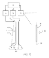
- FIG. 17 is a schematic diagram illustrating yet another directional backlight employing an alternative waveguide structure in which approximately 45° oriented output polarization is provided, in accordance with the present disclosure
- FIG. 18B is an enlarged cross sectional view of polarization recovery embodiment of FIG. 18A , in accordance with the present disclosure
- FIG. 18D is an enlarged cross sectional view of polarization recovery embodiment of FIG. 18C , in accordance with the present disclosure.
- FIG. 19 is a schematic diagram illustrating a side view of a polarisation recovery embodiment, in accordance with the present disclosure.
- FIG. 20 is a schematic diagram illustrating a side view of a detail of the polarisation recovery embodiment of FIG. 19 , in accordance with the present disclosure
- FIG. 21 is a schematic diagram illustrating a schematic front view of the polarisation recovery embodiment of FIG. 19 , in accordance with the present disclosure.
- FIG. 22 is a schematic diagram illustrating a side view of a detail of a further polarisation recovery embodiment, in accordance with the present disclosure.
- Time multiplexed autostereoscopic displays can advantageously improve the spatial resolution of autostereoscopic display by directing light from all of the pixels of a spatial light modulator to a first viewing window in a first time slot, and all of the pixels to a second viewing window in a second time slot.
- Time multiplexed displays can advantageously achieve directional illumination by directing an illuminator array through a substantially transparent time multiplexed spatial light modulator using directional optical elements, wherein the directional optical elements substantially form an image of the illuminator array in the window plane.
- the illuminator elements of the time sequential illumination system may be provided, for example, by pixels of a spatial light modulator with size approximately 100 micrometers in combination with a lens array.
- pixels suffer from similar difficulties as for spatially multiplexed displays. Further, such devices may have low efficiency and higher cost, requiring additional display components.
- High window plane uniformity can be conveniently achieved with macroscopic illuminators, for example, an array of LEDs in combination with homogenizing and diffusing optical elements that are typically of size 1 mm or greater.
- the increased size of the illuminator elements means that the size of the directional optical elements increases proportionately. For example, a 16 mm wide illuminator imaged to a 65 mm wide viewing window may require a 200 mm back working distance.
- the increased thickness of the optical elements can prevent useful application, for example, to mobile displays, or large area displays.
- optical valves as described in commonly-owned U.S. patent application Ser. No. 13/300,293 advantageously can be arranged in combination with fast switching transmissive spatial light modulators to achieve time multiplexed autostereoscopic illumination in a thin package while providing high resolution images with flicker free observer tracking and low levels of cross talk.
- Described is a one dimensional array of viewing positions, or windows, that can display different images in a first, typically horizontal, direction, but contain the same images when moving in a second, typically vertical, direction.
- imaging directional backlights are arranged to direct the illumination from multiple light sources through a display panel to respective multiple viewing windows in at least one axis.
- Each viewing window is substantially formed as an image in at least one axis of a light source by the imaging system of the imaging directional backlight.
- An imaging system may be formed between multiple light sources and the respective window images. In this manner, the light from each of the multiple light sources is substantially not visible for an observer's eye outside of the respective viewing window.
- Non-imaging backlights are used for illumination of 2D displays. See, e.g., Kälil Käläntär et al., Backlight Unit With Double Surface Light Emission , J. Soc. Inf. Display, Vol. 12, Issue 4, pp. 379-387 (December 2004).
- Non-imaging backlights are typically arranged to direct the illumination from multiple light sources through a display panel into a substantially common viewing zone for each of the multiple light sources to achieve wide viewing angle and high display uniformity.
- non-imaging backlights do not form viewing windows. In this manner, the light from each of the multiple light sources may be visible for an observer's eye at substantially all positions across the viewing zone.
- Such conventional non-imaging backlights may have some directionality, for example, to increase screen gain compared to Lambertian illumination, which may be provided by brightness enhancement films such as BEFTM from 3M. However, such directionality may be substantially the same for each of the respective light sources. Thus, for these reasons and others that should be apparent to persons of ordinary skill, conventional non-imaging backlights are different to imaging directional backlights.
- Edge lit non-imaging backlight illumination structures may be used in liquid crystal display systems such as those seen in 2D Laptops, Monitors and TVs. Light propagates from the edge of a lossy waveguide which may include sparse features; typically local indentations in the surface of the guide which cause light to be lost regardless of the propagation direction of the light.
- an optical valve is an optical structure that may be a type of light guiding structure or device referred to as, for example, a light valve, an optical valve directional backlight, and a valve directional backlight (“v-DBL”).
- optical valve is different to a spatial light modulator (even though spatial light modulators may be sometimes generally referred to as a “light valve” in the art).
- One example of an imaging directional backlight is an optical valve that may employ a folded optical system. Light may propagate substantially without loss in one direction through the optical valve, may be incident on an imaging reflector, and may counter-propagate such that the light may be extracted by reflection off tilted light extraction features, and directed to viewing windows as described in U.S. patent application Ser. No. 13/300,293, which is herein incorporated by reference in its entirety.
- an imaging directional backlight examples include a stepped waveguide imaging directional backlight, a folded imaging directional backlight, a wedge type directional backlight, or an optical valve.
- a stepped waveguide imaging directional backlight may be an optical valve.
- a stepped waveguide is a waveguide for an imaging directional backlight including a waveguide for guiding light, further including a first light guiding surface; and a second light guiding surface, opposite the first light guiding surface, further including a plurality of light guiding features interspersed with a plurality of extraction features arranged as steps.
- a folded imaging directional backlight may be at least one of a wedge type directional backlight, or an optical valve.
- light may propagate within an exemplary optical valve in a first direction from an input side to a reflective side and may be transmitted substantially without loss.
- Light may be reflected at the reflective side and propagates in a second direction substantially opposite the first direction.
- the light may be incident on light extraction features, which are operable to redirect the light outside the optical valve.
- the optical valve generally allows light to propagate in the first direction and may allow light to be extracted while propagating in the second direction.
- the optical valve may achieve time sequential directional illumination of large display areas. Additionally, optical elements may be employed that are thinner than the back working distance of the optical elements to direct light from macroscopic illuminators to a window plane. Such displays may use an array of light extraction features arranged to extract light counter propagating in a substantially parallel waveguide.
- Thin imaging directional backlight implementations for use with LCDs have been proposed and demonstrated by 3M, for example U.S. Pat. No. 7,528,893; by Microsoft, for example U.S. Pat. No. 7,970,246 which may be referred to herein as a “wedge type directional backlight;” by RealD, for example U.S. patent application Ser. No. 13/300,293 which may be referred to herein as an “optical valve” or “optical valve directional backlight,” all of which are herein incorporated by reference in their entirety.
- the present disclosure provides stepped waveguide imaging directional backlights in which light may reflect back and forth between the internal faces of, for example, a stepped waveguide which may include a first side and a first set of features. As the light travels along the length of the stepped waveguide, the light may not substantially change angle of incidence with respect to the first side and first set of surfaces and so may not reach the critical angle of the medium at these internal faces. Light extraction may be advantageously achieved by a second set of surfaces (the step “risers”) that are inclined to the first set of surfaces (the step “treads”). Note that the second set of surfaces may not be part of the light guiding operation of the stepped waveguide, but may be arranged to provide light extraction from the structure.
- a wedge type imaging directional backlight may allow light to guide within a wedge profiled waveguide having continuous internal surfaces. The optical valve is thus not a wedge type imaging directional backlight.
- FIG. 1A is a schematic diagram illustrating a front view of light propagation in one embodiment of a directional display device
- FIG. 1B is a schematic diagram illustrating a side view of light propagation in the directional display device of FIG. 1A .
- FIG. 1A illustrates a front view in the xy plane of a directional backlight of a directional display device, and includes an illuminator array 15 which may be used to illuminate a stepped waveguide 1 .
- Illuminator array 15 includes illuminator elements 15 a through illuminator element 15 n (where n is an integer greater than one).
- the stepped waveguide 1 of FIG. 1A may be a stepped, display sized waveguide 1 .
- Illumination elements 15 a through 15 n are light sources that may be light emitting diodes (LEDs).
- FIG. 1B illustrates a side view in the xz plane, and includes illuminator array 15 , SLM (spatial light modulator) 48 , extraction features 12 , guiding features 10 , and stepped waveguide 1 , arranged as shown.
- the side view provided in FIG. 1B is an alternative view of the front view shown in FIG. 1A . Accordingly, the illuminator array 15 of FIGS. 1A and 1B corresponds to one another and the stepped waveguide 1 of FIGS. 1A and 1B may correspond to one another.
- the stepped waveguide 1 may have an input end 2 that is thin and a reflective end 4 that is thick.
- the waveguide 1 extends between the input end 2 that receives input light and the reflective end 4 that reflects the input light back through the waveguide 1 .
- the length of the input end 2 in a lateral direction across the waveguide is greater than the height of the input end 2 .
- the illuminator elements 15 a - 15 n are disposed at different input positions in a lateral direction across the input end 2 .
- the waveguide 1 has first and second, opposed guide surfaces extending between the input end 2 and the reflective end 4 for guiding light forwards and back along the waveguide 1 by total internal reflection.
- the first guide surface is planar.
- the second guide surface has a plurality of light extraction features 12 facing the reflective end 4 and inclined to reflect at least some of the light guided back through the waveguide 1 from the reflective end in directions that break the total internal reflection at the first guide surface and allow output through the first guide surface, for example, upwards in FIG. 1B , that is supplied to the SLM 48 .
- the light extraction features 12 are reflective facets, although other reflective features could be used.
- the light extraction features 12 do not guide light through the waveguide, whereas the intermediate regions of the second guide surface intermediate the light extraction features 12 guide light without extracting it. Those regions of the second guide surface are planar and may extend parallel to the first guide surface, or at a relatively low inclination.
- the light extraction features 12 extend laterally to those regions so that the second guide surface has a stepped shape including of the light extraction features 12 and intermediate regions.
- the light extraction features 12 are oriented to reflect light from the light sources, after reflection from the reflective end 4 , through the first guide surface.
- the light extraction features 12 are arranged to direct input light from different input positions in the lateral direction across the input end in different directions relative to the first guide surface that are dependent on the input position.
- the illumination elements 15 a - 15 n are arranged at different input positions, the light from respective illumination elements 15 a - 15 n is reflected in those different directions.
- each of the illumination elements 15 a - 15 n directs light into a respective optical window in output directions distributed in the lateral direction in dependence on the input positions.
- the lateral direction across the input end 2 in which the input positions are distributed corresponds with regard to the output light to a lateral direction to the normal to the first guide surface.
- the illuminator elements 15 a - 15 n may be selectively operated to direct light into a selectable optical window.
- the optical windows may be used individually or in groups as viewing windows.
- the SLM 48 extends across the waveguide is transmissive and modulates the light passing therethrough.
- the SLM 48 may be a liquid crystal display (LCD) but this is merely by way of example, and other spatial light modulators or displays may be used including LCOS, DLP devices, and so forth, as this illuminator may work in reflection.
- the SLM 48 is disposed across the first guide surface of the waveguide and modulates the light output through the first guide surface after reflection from the light extraction features 12 .
- FIG. 1A The operation of a directional display device that may provide a one dimensional array of viewing windows is illustrated in front view in FIG. 1A , with its side profile shown in FIG. 1B .
- the light may propagate along +x in a first direction, within the stepped waveguide 1 , while at the same time, the light may fan out in the xy plane and upon reaching the far curved end side 4 , may substantially or entirely fill the curved end side 4 . While propagating, the light may spread out to a set of angles in the xz plane up to, but not exceeding the critical angle of the guide material.
- the extraction features 12 that link the guiding features 10 of the bottom side of the stepped waveguide 1 may have a tilt angle greater than the critical angle and hence may be missed by substantially all light propagating along +x in the first direction, ensuring the substantially lossless forward propagation.
- the curved end side 4 of the stepped waveguide 1 may be made reflective, typically by being coated with a reflective material such as, for example, silver, although other reflective techniques may be employed.
- Light may therefore be redirected in a second direction, back down the guide in the direction of ⁇ x and may be substantially collimated in the xy or display plane.
- the angular spread may be substantially preserved in the xz plane about the principal propagation direction, which may allow light to hit the riser edges and reflect out of the guide.
- light may be effectively directed approximately normal to the xy display plane with the xz angular spread substantially maintained relative to the propagation direction. This angular spread may be increased when light exits the stepped waveguide 1 through refraction, but may be decreased somewhat dependent on the reflective properties of the extraction features 12 .
- reflection may be reduced when total internal reflection (TIR) fails, squeezing the xz angular profile and shifting off normal.
- TIR total internal reflection
- the increased angular spread and central normal direction may be preserved.
- light may exit the stepped waveguide 1 approximately collimated and may be directed off normal in proportion to the y-position of the respective illuminator element 15 a - 15 n in illuminator array 15 from the input edge center. Having independent illuminator elements 15 a - 15 n along the input edge 2 then enables light to exit from the entire first light directing side 6 and propagate at different external angles, as illustrated in FIG. 1A .
- Illuminating a spatial light modulator (SLM) 48 such as a fast liquid crystal display (LCD) panel with such a device may achieve autostereoscopic 3D as shown in top view or yz-plane viewed from the illuminator array 15 end in FIG. 2A , front view in FIG. 2B and side view in FIG. 2C .
- FIG. 2A is a schematic diagram illustrating in a top view, propagation of light in a directional display device
- FIG. 2B is a schematic diagram illustrating in a front view, propagation of light in a directional display device
- FIG. 2C is a schematic diagram illustrating in side view propagation of light in a directional display device.
- FIGS. 1 spatial light modulator
- a stepped waveguide 1 may be located behind a fast (e.g., greater than 100 Hz) LCD panel SLM 48 that displays sequential right and left eye images.
- a fast e.g., greater than 100 Hz
- specific illuminator elements 15 a through 15 n of illuminator array 15 may be selectively turned on and off, providing illuminating light that enters right and left eyes substantially independently by virtue of the system's directionality.
- sets of illuminator elements of illuminator array 15 are turned on together, providing a one dimensional viewing window 26 or an optical pupil with limited width in the horizontal direction, but extended in the vertical direction, in which both eyes horizontally separated may view a left eye image, and another viewing window 44 in which a right eye image may primarily be viewed by both eyes, and a central position in which both the eyes may view different images.
- 3D may be viewed when the head of a viewer is approximately centrally aligned. Movement to the side away from the central position may result in the scene collapsing onto a 2D image.
- the reflective end 4 may have positive optical power in the lateral direction across the waveguide.
- the optical axis may be defined with reference to the shape of the reflective end 4 , for example being a line that passes through the centre of curvature of the reflective end 4 and coincides with the axis of reflective symmetry of the end 4 about the x-axis.
- the optical axis may be similarly defined with respect to other components having optical power, for example the light extraction features 12 if they are curved, or the Fresnel lens 62 described below.
- the optical axis 238 is typically coincident with the mechanical axis of the waveguide 1 .
- the cylindrical reflecting surface at end 4 may typically be a spherical profile to optimize performance for on-axis and off-axis viewing positions. Other profiles may be used.
- FIG. 3 is a schematic diagram illustrating in side view a directional display device. Further, FIG. 3 illustrates additional detail of a side view of the operation of a stepped waveguide 1 , which may be a transparent material.
- the stepped waveguide 1 may include an illuminator input side 2 , a reflective side 4 , a first light directing side 6 which may be substantially planar, and a second light directing side 8 which includes guiding features 10 and light extraction features 12 .
- light rays 16 from an illuminator element 15 c of an illuminator array 15 (not shown in FIG.
- reflective side 4 may be a mirrored surface and may reflect light, it may in some embodiments also be possible for light to pass through reflective side 4 .
- light ray 18 reflected by the reflective side 4 may be further guided in the stepped waveguide 1 by total internal reflection at the reflective side 4 and may be reflected by extraction features 12 .
- Light rays 18 that are incident on extraction features 12 may be substantially deflected away from guiding modes of the stepped waveguide 1 and may be directed, as shown by ray 20 , through the side 6 to an optical pupil that may form a viewing window 26 of an autostereoscopic display.
- the width of the viewing window 26 may be determined by at least the size of the illuminator, output design distance and optical power in the side 4 and extraction features 12 .
- each viewing window 26 represents a range of separate output directions with respect to the surface normal direction of the spatial light modulator 48 that intersect with a plane at the nominal viewing distance.
- FIG. 4A is a schematic diagram illustrating in front view a directional display device which may be illuminated by a first illuminator element and including curved light extraction features. Further, FIG. 4A shows in front view further guiding of light rays from illuminator element 15 c of illuminator array 15 , in the stepped waveguide 1 having an optical axis 28 .
- the directional backlight may include the stepped waveguide 1 and the light source illuminator array 15 .
- Each of the output rays are directed from the input side 2 towards the same viewing window 26 from the respective illuminator 15 c .
- the light rays of FIG. 4A may exit the reflective side 4 of the stepped waveguide 1 .
- ray 16 may be directed from the illuminator element 15 c towards the reflective side 4 .
- Ray 18 may then reflect from a light extraction feature 12 and exit the reflective side 4 towards the viewing window 26 .
- light ray 30 may intersect the ray 20 in the viewing window 26 , or may have a different height in the viewing window as shown by ray 32 .
- sides 22 , 24 of the waveguide 1 may be transparent, mirrored, or blackened surfaces.
- light extraction features 12 may be elongate, and the orientation of light extraction features 12 in a first region 34 of the light directing side 8 (light directing side 8 shown in FIG. 3 , but not shown in FIG.
- the stepped waveguide 1 may include a reflective surface on reflective side 4 .
- the reflective end of the stepped waveguide 1 may have positive optical power in a lateral direction across the stepped waveguide 1 .
- the light extraction features 12 of each directional backlight may have positive optical power in a lateral direction across the waveguide.
- each directional backlight may include light extraction features 12 which may be facets of the second guide surface.
- the second guide surface may have regions alternating with the facets that may be arranged to direct light through the waveguide without substantially extracting it.
- FIG. 4B is a schematic diagram illustrating in front view a directional display device which may illuminated by a second illuminator element. Further, FIG. 4B shows the light rays 40 , 42 from a second illuminator element 15 h of the illuminator array 15 . The curvature of the reflective surface on the side 4 and the light extraction features 12 cooperatively produce a second viewing window 44 laterally separated from the viewing window 26 with light rays from the illuminator element 15 h.
- the arrangement illustrated in FIG. 4B may provide a real image of the illuminator element 15 c at a viewing window 26 in which the real image may be formed by cooperation of optical power in reflective side 4 and optical power which may arise from different orientations of elongate light extraction features 12 between regions 34 and 36 , as shown in FIG. 4A .
- the arrangement of FIG. 4B may achieve improved aberrations of the imaging of illuminator element 15 c to lateral positions in viewing window 26 . Improved aberrations may achieve an extended viewing freedom for an autostereoscopic display while achieving low cross talk levels.
- FIG. 5 is a schematic diagram illustrating in front view an embodiment of a directional display device having substantially linear light extraction features. Further, FIG. 5 shows a similar arrangement of components to FIG. 1 (with corresponding elements being similar), with one of the differences being that the light extraction features 12 are substantially linear and parallel to each other. Advantageously, such an arrangement may provide substantially uniform illumination across a display surface and may be more convenient to manufacture than the curved extraction features of FIG. 4A and FIG. 4B .
- the optical axis 321 of the directional waveguide 1 may be the optical axis direction of the surface at side 4 .
- the optical power of the side 4 is arranged to be across the optical axis direction, thus rays incident on the side 4 will have an angular deflection that varies according to the lateral offset 319 of the incident ray from the optical axis 321 .
- FIG. 6A is a schematic diagram illustrating one embodiment of the generation of a first viewing window in a time multiplexed imaging directional display device in a first time slot
- FIG. 6B is a schematic diagram illustrating another embodiment of the generation of a second viewing window in a time multiplexed imaging directional backlight apparatus in a second time slot
- FIG. 6C is a schematic diagram illustrating another embodiment of the generation of a first and a second viewing window in a time multiplexed imaging directional display device.
- FIG. 6A shows schematically the generation of viewing window 26 from stepped waveguide 1 .
- Illuminator element group 31 in illuminator array 15 may provide a light cone 17 directed towards a viewing window 26 .
- Illuminator element group 33 in illuminator array 15 may provide a light cone 19 directed towards viewing window 44 .
- windows 26 and 44 may be provided in sequence as shown in FIG. 6C . If the image on a spatial light modulator 48 (not shown in FIGS. 6A, 6B, 6C ) is adjusted in correspondence with the light direction output, then an autostereoscopic image may be achieved for a suitably placed viewer. Similar operation can be achieved with all the imaging directional backlights described herein.
- illuminator element groups 31 , 33 each include one or more illumination elements from illumination elements 15 a to 15 n , where n is an integer greater than one.
- FIG. 7 is a schematic diagram illustrating one embodiment of an observer tracking autostereoscopic display apparatus including a time multiplexed directional display device.
- selectively turning on and off illuminator elements 15 a to 15 n along axis 29 provides for directional control of viewing windows.
- the head 45 position may be monitored with a camera, motion sensor, motion detector, or any other appropriate optical, mechanical or electrical means, and the appropriate illuminator elements of illuminator array 15 may be turned on and off to provide substantially independent images to each eye irrespective of the head 45 position.
- the head tracking system (or a second head tracking system) may provide monitoring of more than one head 45 , 47 (head 47 not shown in FIG. 7 ) and may supply the same left and right eye images to each viewers' left and right eyes providing 3D to all viewers. Again similar operation can be achieved with all the imaging directional backlights described herein.
- FIG. 8 is a schematic diagram illustrating one embodiment of a multi-viewer directional display device as an example including an imaging directional backlight.
- at least two 2D images may be directed towards a pair of viewers 45 , 47 so that each viewer may watch a different image on the spatial light modulator 48 .
- the two 2D images of FIG. 8 may be generated in a similar manner as described with respect to FIG. 7 in that the two images would be displayed in sequence and in synchronization with sources whose light is directed toward the two viewers.
- One image is presented on the spatial light modulator 48 in a first phase
- a second image is presented on the spatial light modulator 48 in a second phase different from the first phase.
- the output illumination is adjusted to provide first and second viewing windows 26 , 44 respectively. An observer with both eyes in viewing window 26 will perceive a first image while an observer with both eyes in viewing window 44 will perceive a second image.
- FIG. 9 is a schematic diagram illustrating a privacy directional display device which includes an imaging directional backlight.
- 2D display systems may also utilize directional backlighting for security and efficiency purposes in which light may be primarily directed at the eyes of a first viewer 45 as shown in FIG. 9 .
- first viewer 45 may be able to view an image on device 50
- light is not directed towards second viewer 47 .
- second viewer 47 is prevented from viewing an image on device 50 .
- Each of the embodiments of the present disclosure may advantageously provide autostereoscopic, dual image or privacy display functions.
- FIG. 10 is a schematic diagram illustrating in side view the structure of a time multiplexed directional display device as an example including an imaging directional backlight. Further, FIG. 10 shows in side view an autostereoscopic directional display device, which may include the stepped waveguide 1 and a Fresnel lens 62 arranged to provide the viewing window 26 for a substantially collimated output across the stepped waveguide 1 output surface. A vertical diffuser 68 may be arranged to extend the height of the viewing window 26 further. The light may then be imaged through the spatial light modulator 48 .
- the illuminator array 15 may include light emitting diodes (LEDs) that may, for example, be phosphor converted blue LEDs, or may be separate RGB LEDs.
- LEDs light emitting diodes
- the illuminator elements in illuminator array 15 may include a uniform light source and spatial light modulator arranged to provide separate illumination regions.
- the illuminator elements may include laser light source(s).
- the laser output may be directed onto a diffuser by means of scanning, for example, using a galvo or MEMS scanner.
- laser light may thus be used to provide the appropriate illuminator elements in illuminator array 15 to provide a substantially uniform light source with the appropriate output angle, and further to provide reduction in speckle.
- the illuminator array 15 may be an array of laser light emitting elements.
- the diffuser may be a wavelength converting phosphor, so that illumination may be at a different wavelength to the visible output light.
- FIG. 11A is a schematic diagram illustrating a front view of another imaging directional backlight, as illustrated, a wedge type directional backlight
- FIG. 11B is a schematic diagram illustrating a side view of the same wedge type directional display device.
- a wedge type directional backlight is generally discussed by U.S. Pat. No. 7,660,047 and entitled “Flat Panel Lens,” which is herein incorporated by reference in its entirety.
- the structure may include a wedge type waveguide 1104 with a bottom surface which may be preferentially coated with a reflecting layer 1106 and with an end corrugated surface 1102 , which may also be preferentially coated with a reflecting layer 1106 .
- a directional display device may include a waveguide, such as a wedge type waveguide 1104 , having an input end, first and second opposed guide surfaces for guiding light along the waveguide, and a reflective end facing the input end for reflecting light from the input light back through the waveguide.
- the directional display device may also include an array of light sources disposed at different input positions across the input end of the waveguide.
- the waveguide may be arranged to direct input light from the light sources as output light through the first guide surface after reflection from the reflective end into optical windows in output directions relative to the normal to the first guide surface and may be primarily dependent on the input positions.
- the directional display device may also include a transmissive spatial light modulator, such as display panel 1110 , arranged to receive the output light from the first guide surface and arranged to modulate a first polarization component of the output light having a first polarization. Further, the directional display device may also include a reflective polarizer disposed between the first guide surface of the waveguide and the spatial light modulator and arranged to transmit the first polarization component and to reflect a second polarization component of the output light having a polarization orthogonal to the first polarization as rejected light. The directional display device may also include a rear reflector disposed behind the second guide surface arranged to reflect the rejected light for supply back to the spatial light modulator. The directional display device may further be arranged to convert the polarization of the rejected light supplied back to spatial light modulator into the first polarization.
- a transmissive spatial light modulator such as display panel 1110 , arranged to receive the output light from the first guide surface and arranged to modulate a first polarization
- the first guide surface may be arranged to guide light by total internal reflection and the second guide surface may be substantially planar and inclined at an angle to reflect light in directions that break the total internal reflection for outputting light through the first guide surface.
- the wedge type directional backlight may be part of a directional display device.
- the directional display device may also include a deflection element extending across the first guide surface of the waveguide for deflecting light towards the normal to the spatial light modulator.
- light may enter the wedge type waveguide 1104 from local sources 1101 and the light may propagate in a first direction before reflecting off the end surface.
- Light may exit the wedge type waveguide 1104 while on its return path and may illuminate a display panel 1110 .
- a wedge type waveguide provides extraction by a taper that reduces the incidence angle of propagating light so that when the light is incident at the critical angle on an output surface, it may escape. Escaping light at the critical angle in the wedge type waveguide propagates substantially parallel to the surface until deflected by a redirection layer 1108 such as a prism array.
- Errors or dust on the wedge type waveguide output surface may change the critical angle, creating stray light and uniformity errors.
- an imaging directional backlight that uses a mirror to fold the beam path in the wedge type directional backlight may employ a faceted mirror that biases the light cone directions in the wedge type waveguide. Such faceted mirrors are generally complex to fabricate and may result in illumination uniformity errors as well as stray light.
- FIG. 12 is a schematic diagram illustrating a directional display apparatus including a display device 100 and a control system. The arrangement and operation of the control system will now be described and may be applied, with changes as necessary, to each of the display devices disclosed herein.
- the directional display device 100 includes a directional backlight that includes waveguide 1 and an array of illuminator elements 15 arranged as described above.
- the control system is arranged to selectively operate the illumination elements 15 a - 15 n to direct light into selectable viewing windows.
- the waveguide 1 is arranged as described above.
- the reflective end 4 converges the reflected light.
- a Fresnel lens 62 may be arranged to cooperate with reflective end 4 to achieve viewing windows 26 at a viewing plane 106 observed by an observer 99 .
- a transmissive spatial light modulator (SLM) 48 may be arranged to receive the light from the directional backlight. Further a diffuser 68 may be provided to substantially remove Moire beating between the waveguide 1 and pixels of the SLM 48 as well as the Fresnel lens 62 .
- SLM spatial light modulator
- the control system may include a sensor system arranged to detect the position of the observer 99 relative to the display device 100 .
- the sensor system includes a position sensor 70 , such as a camera, and a head position measurement system 72 that may for example include a computer vision image processing system.
- the control system may further include an illumination controller 74 and an image controller 76 that are both supplied with the detected position of the observer supplied from the head position measurement system 72 .
- the illumination controller 74 selectively operates the illuminator elements 15 to direct light to into the viewing windows 26 in cooperation with waveguide 1 .
- the illumination controller 74 selects the illuminator elements 15 to be operated in dependence on the position of the observer detected by the head position measurement system 72 , so that the viewing windows 26 into which light is directed are in positions corresponding to the left and right eyes of the observer 99 . In this manner, the lateral output directionality of the waveguide 1 corresponds with the observer position.
- the image controller 76 controls the SLM 48 to display images.
- the image controller 76 and the illumination controller 74 may operate as follows.
- the image controller 76 controls the SLM 48 to display temporally multiplexed left and right eye images.
- the illumination controller 74 operate the light sources 15 to direct light into viewing windows in positions corresponding to the left and right eyes of an observer synchronously with the display of left and right eye images. In this manner, an autostereoscopic effect is achieved using a time division multiplexing technique.
- a directional backlight device may include a stepped waveguide 1 and a light source illuminator array 15 .
- the stepped waveguide 1 includes a light directing side 8 , a reflective side 4 , guiding features 10 and light extraction features 12 .
- a directional display device may further include a control system which may be arranged to selectively operate the light sources to direct light into viewing windows corresponding to output directions as previously discussed.
- This embodiment may also be used in conjunction with any of the directional backlights, directional display devices, directional display apparatuses, and so forth as described herein.
- a directional display apparatus may be an autostereoscopic display apparatus with a control system.
- the control system may be further arranged to control the directional display device to temporally display multiplexed left and right images and to substantially synchronously direct the displayed images into viewing windows in positions corresponding to at least the left and right eyes of an observer.
- the control system may include a sensor system which may be arranged to detect the position of an observer across the display device, and also may be arranged to direct the displayed images into viewing windows in positions corresponding to at least the left and right eyes of an observer. The position of the viewing windows may primarily depend on the detected position of the observer.
- FIG. 13A is a schematic diagram illustrating a polarization recovery approach employed with a wedge type waveguide structure employing a wedge type waveguide 1104 having the arrangement shown and described with reference to FIG. 11B .
- the top surface of the waveguide of a wedge type directional backlight 1104 may be coated with layers 1202 of alternating high and low refractive index materials to provide polarization selective reflection and transmission for those rays 1206 and 1208 that exit.
- the layers 1202 formed on the first guide surface of the waveguide may form a reflective polarizer by (1) transmitting a first polarization component of the output light from the first guide surface of the waveguide, the first polarization component having a first polarization, and (2) reflecting a second polarization component of the output light as rejected light, the second polarization component having a polarization orthogonal to the first polarization.
- the narrow range of angles with which light exits this wedge type directional backlight may enable high polarization selectivity with very few coating layers 1202 .
- a rear reflecting layer 1212 that functions as a rear reflector is formed on the second guide surface of the waveguide.
- a retarder film 1214 laminated to the bottom of the waveguide or the second guide surface of the waveguide, may transform the polarization of reflected light to exit following reflection from the reflecting layer 1212 .
- Unpolarised light ray 1204 is incident on layers 1202 so that ray 1206 is output with a first polarization state and ray 1210 is reflected with a second polarization state orthogonal to the first polarization state, rotated by layer 1212 and output as ray 1208 in the first polarization state.
- the retarder film 1214 functions as a phase retarder and may be disposed between the reflective polarizer formed by the layers 1202 and the rear reflector formed by the reflecting layer 212 .
- the retarder film 1214 may be arranged to convert the polarization of the rejected light into the first polarization when the light exits the wedge type waveguide 1104 for supply back to a spatial light modulator.
- FIG. 13B is a schematic diagram illustrating the elements of a polarization recovery system. Further, FIG. 13B illustrates a general embodiment of the current disclosure.
- Imaging directional backlight systems may illuminate with unpolarized light 1302 to provide polarized light for LCDs a polarizing sheet may be used which may absorb at least 50% of the illuminating light. Recovery of this absorbed light may be possible by introducing a reflecting polarizer layer 1306 which functions as a reflective polarizer.
- the reflecting polarizer layer 1306 while allowing transmission of light of the desired first polarization component 1310 of a first polarization, may reflect the otherwise lost second polarization component 1314 having a polarization orthogonal to the first polarization, as rejected light.
- This reflected component then can be altered in polarization most efficiently by a quarter wave retarder 1304 oriented at approximately 45° to the polarization axis of the light that functions as a phase retarder. Redirection of the light through reflection off of mirror 1308 may cause the light to complete a second pass through the quarter wave retarder 1304 , thus substantially completing the polarization transformation and allowing efficient transmission through the reflecting polarizer 1306 as well as making the light 1312 propagate approximately parallel to the light originally transmitted 1310 . In an ideal case little to no light may be lost and the directionality of the combined illumination may be substantially preserved.
- the polarization conversion and redirection of the reflected component can be achieved by other means such as scattering which may be a property of the underlying backlight illuminator. To achieve some measure of polarization recovery therefore may employ a minimum of a reflecting polarization element.
- the embodiments of the current disclosure may not rely on reflection of a narrow band, approximately less than 2° of polarized exiting rays and may employ a reflecting polarizer capable of acting on rays at angles with a spread up to and beyond approximately 450 of display viewing angles.
- FIG. 14A is a schematic diagram illustrating a directional backlight employing a polarization recovery approach
- FIG. 14B is a schematic diagram illustrating a system side view of the directional backlight of FIG. 14A
- FIG. 14A shows an embodiment of a waveguide structure of the directional backlight with its side view shown in FIG. 14B , arranged as follows.
- a stepped waveguide 1406 may have the stepped surface 1502 (first guide surface) coated with a reflecting material such as, but not limited to, Silver or Aluminum to form the rear reflector.
- Light rays 1401 propagating within the valve 1406 and reflected from light extraction features of the surface 1502 may be substantially unpolarised. After transmission through a phase retarder such as a quarter wave retarder 1404 , the light remains unpolarised.
- Light rays 1405 of the desired vertical polarization state 1403 are transmitted through reflective polarizer 1408 and clean-up sheet polarizer 1410 with a vertical polarization transmission orientation for transmission through spatial light modulator 48 .
- Such rays 1405 may be transmitted through the spatial light modulator with substantially no change to the directionality of the light.
- a reflective polarizer 1408 is arranged in front of the stepped waveguide 1406 and a quarter wave retarder 1404 that functions as a phase retarder may be disposed between the stepped waveguide 1406 and the reflective polarizer 1408 , and thus between the rear reflector formed on the stepped surface 1502 and the reflective polarizer 1408 .
- Light rays 1407 of the undesired horizontal linear polarization state 1409 may exit the stepped waveguide 1406 and be reflected from the reflective polarizer 1408 as reflected light. Residual transmission of light in the horizontal polarization state 1409 by the reflective polarizer 1408 may be cleaned up by a sheet polarizer 1410 arranged in front of the reflective polarizer 1408 .
- the quarter wave retarder 1404 may be arranged to convert the polarization of the rejected light into the first polarization when supplied back to the spatial light modulator (not shown) that is arranged in front of the sheet polarizer 1410 , as follows. Rejected rays 1407 with a horizontal polarization state may pass back through a quarter wave retarder 1404 with an optical axis oriented at approximately 45°, and thus be converted to circular polarization state 1411 . The respective reflected light may then be transmitted through the transparent optical valve 1406 before being further reflected from the back stepped surface 1502 of the waveguide 1406 .
- the circular polarization state 1411 of light rays 1407 may be converted on reflection to orthogonal circular polarization state 1413 and become predominantly transformed into the desired vertical polarization state 1417 following a second pass through quarter wave retarder 1404 achieving transmission through reflective polarizer 1408 and clean up polarizer 1410 .
- the rays 1415 may then combine with those rays 1405 originally transmitted by polariser 1410 to form a substantially uniformly polarized directed beam of effectively substantially twice the original intensity and with the substantially the same directionality.
- the intensity of viewing windows may be increased with low image cross talk.
- Small loss of intensity of light rays 1415 may be provided by reduced reflectivity at the side 1502 and other additional losses from Fresnel reflections of the reflected rays 1407 .
- the quarter wave retarder 1404 may be a single layer retarder with a single optical axis direction.
- retarder layer stacks with increased number of layers and combination of retardances and optical axis directions may be arranged to increase the spectral bandwidth of the retarder as is known.
- the optical axes of the respective retarders of the stack of retarders may thus be arranged to convert light from linear to circular polarization states as required.
- the polarization state 1403 , 1417 may be arranged to be aligned with the desired input polarization direction of polarizer 1410 and may be at +/ ⁇ 45° for twisted nematic liquid crystal modes, or may be vertical or horizontal for other known optical modes such as vertical alignment modes.
- the reflective polarizer 1408 may be approximately parallel with respect to the reflecting surface 1502 and may for example be arranged on the input to the spatial light modulator 48 to provide a substantially planar surface. This can be achieved with a flexible film attached for example by means of lamination onto the clean-up polarizer film adjacent, or directly onto the panel.
- the clean-up polarizer may typically include an absorption polarizer such as iodine and stretched film. This can be achieved with a flexible film attached with the clean-up polarizer film adjacent, or directly onto the panel.
- a suitable reflective polarizer may be the multi-layer birefringent film for example, a product DBEF supplied by 3M.
- Another candidate may be a periodic metal wire grid structure on glass with periodicity below the wavelength of visible light such as that supplied by Moxtek.
- the reflective polarizer as discussed herein may be a similar metal grid structure may be provided on film stock by Asai Kasei.
- Efficient polarization transformation may be achieved when the material of the stepped waveguide 1406 exhibits little to no birefringence.
- the birefringence may then be compensated by an extra retarder film or more preferably subtracted from a substantially parallel aligned quarter wave retarder.
- the film orientations may be preferably oriented with an optical axis at approximately 45 degrees to the orientation shown in FIGS. 14A and 14B .
- any additional optical elements such as asymmetric diffusers or Fresnel lenses may be located between the reflective polarizer 1408 and the sheet polarizer 1410 .
- the orientation of the greatest scattering may be vertical as illustrated by FIG. 14B .
- Optical valves in a basic form may act to image in the horizontal plane and may be tolerant to vertical scattering.
- FIG. 15A is a schematic diagram illustrating another system schematic of a directional backlight employing a polarization recovery approach based on a waveguide
- FIG. 15B is a schematic diagram illustrating a system side view illustration of the directional backlight of FIG. 15A
- FIGS. 15A and 15B show an additional embodiment of the current disclosure.
- the waveguide structure of this directional backlight may employ a waveguide 1406 , reflective polarizer 1408 , and sheet polarizer 1410 as described above.
- a mirrored coating on the stepped surface 1502 (first guide surface) of the waveguide there may be a separate reflector layer 1402 behind the waveguide 1406 that acts as the rear reflector, and the quarter wave retarder 1404 may be arranged behind the waveguide, in particular between the waveguide and the reflector layer 1402 , as illustrated in FIGS. 15A and 15B .
- the reflective polarizer may be layers of material of alternating high and low refractive index.
- light rays 1415 , 1405 may be achieved with substantially the same directionality and polarization state. This embodiment operates in the same manner as the embodiment of FIGS. 14A and 14B .
- the stepped surface may reduce scattering and cost. Also in placing the retarder layer behind the waveguide, light with linear polarization states may be back reflected through the stepped waveguide providing tolerance to non-uniform, though parallel oriented, birefringence which may be expected in any molded parts.
- the most common direction of the optical axis of birefringence of the waveguide 1406 may be arranged to be parallel to or orthogonal to the polarization state 1417 to achieve reduced non uniformities of polarization conversion and thus reduced display non uniformities.
- FIG. 16A is a schematic diagram illustrating another directional backlight employing a polarization recovery approach based on an alternative waveguide structure. Further, FIG. 16A is another embodiment in which an alternate waveguide structure may be employed. Similar to FIG. 14A , as illustrated, the waveguide structure of FIG. 16A includes a stepped waveguide 1406 , a quarter wave retarder 1404 , a reflective polarizer 1408 , and a sheet polarizer 1410 arranged and operating in the same manner as the embodiment of FIG. 14A . In FIG.
- the curved reflector end of the stepped waveguide 1406 may be replaced by a Fresnel reflector equivalent structure, and curved extraction steps may render extraneous any further imaging element on the system such as Fresnel lens 62 shown in FIG. 12 .
- the stepped surface 1502 of the waveguide 1406 may be directly coated with a reflecting coating to back reflect light for polarization recovery as described for previous embodiments.
- FIG. 16B is a schematic diagram illustrating yet another directional backlight employing polarization recovery approach based on another alternative waveguide structure.
- FIG. 16B is a related system embodiment in which an additional polarization rotation film 1602 is disposed between the reflective polarizer 1408 and the spatial light modulator (not shown).
- the polarization rotation film 1602 acts as a polarization rotator that rotates the first polarization component output from the reflective polarizer 1408 prior to supply to the SLM. This may be used to transform the output linear polarization state 1405 , 1417 to polarization state 1419 from retarder 1602 that may be a half wave retarder that may be a wide band retarder stack with appropriately oriented optical axes.
- polarisation state 1421 is oriented at approximately 45 degrees to the vertical for more optimum operation with twisted nematic (TN) liquid crystal display (LCD) panels.
- TN twisted nematic
- LCD liquid crystal display
- a substantially parallel 450 aligned clean-up polarizer sheet 1604 may be used in place of the sheet polarizer 1410 to provide highly polarized light at the appropriate orientation for high contrast operation.
- a directional display device may include a stepped waveguide 1406 , a quarter wave retarder 1404 , a polarization sensitive layer 1408 , and a sheet polarizer 1410 .
- the directional display device may further include a polarization rotator disposed between the reflective polarizer and a spatial light modulator. The polarization rotator may be arranged to rotate the first polarization component.
- FIG. 17 is a schematic diagram illustrating another directional backlight employing a polarization recovery approach modified as compared to the embodiment of FIG. 16B to provide an alternative optical valve structure in which approximately 45° oriented output polarization is provided.
- FIG. 17 is yet another directional backlight employing a polarization recovery approach with film orientations rotated by approximately 45° for direct recovery of TN desired polarized light.
- polarization states 1423 , 1425 may be arranged at angles other than horizontal and vertical and retarder 1606 arranged to cooperate with the incident polarisation states to achieve polarisation rotation as described above.
- the orientation of quarter wave retarder 1606 may be substantially parallel to the physical sides of the optical valve and oriented with respect to any residual birefringence. Choosing a retardation value different to that of a quarter-wave may act to compensate for any residual waveguide birefringence.
- FIG. 18A is a schematic diagram illustrating an embodiment in which the polarizing reflecting layer is integrated in a single film with the beam deflecting function within a wedge type directional backlight with further detail illustrated in FIG. 18B .
- FIGS. 18A and 18B illustrate an embodiment in which polarization recovery may be employed with a wedge type directional waveguide.
- a polarization sensitive reflector layer may be coated onto facets 1810 of a redirection film 1108 .
- the wedge type directional backlight may operate in such a way as to provide an unpolarized, though directed, exiting beam 1802 that may propagate at small angles from the exiting surface.
- Light within this beam of the undesired polarization state may be reflected downwards off the polarization sensitive reflector layer on facets 1810 and away from the illumination direction.
- Light 1804 of the desired polarized state may be allowed to be transmitted and redirected upward.
- the downward propagating beam may pass through the transparent wedge guide material and may be both transformed and redirected back by the quarter wave retarder 1814 and reflecting surface 1106 . This transformed light may pass back through the waveguide 1104 and redirection film 1108 to combine with the initial light beam of the desired polarization.
- a directional display device may include a waveguide in which a first guide surface may be arranged to guide light by total internal reflection and a second guide surface may include a plurality of light extraction features.
- the light extraction features may be oriented to reflect light guided through the waveguide in directions allowing exit through the first guide surface as the output light.
- the second guide surface may also include intermediate regions between the light extraction features that may be arranged to direct light through the waveguide without substantially extracting it.
- the light extraction features may be facets of the second guide surface and the second guide surface may have a stepped shape that may include the reflective facets and the intermediate regions.
- FIG. 18C is a schematic diagram illustrating another polarization recovery embodiment within a wedge type directional backlight with further detail shown in FIG. 18D .
- FIG. 18D is an enlarged cross sectional view of polarization recovery embodiment of FIG. 18C .
- FIG. 18B illustrates a related embodiment to that of FIG. 18A in which the quarter wave retarder 1814 may be located on the exiting surface of the waveguide rather than between the waveguide and the reflection layer 1812 .
- FIG. 19 is a schematic diagram illustrating a side view of a polarization recovery embodiment.
- the embodiment is generally similar to that shown in FIG. 15A and described above but modified so that instead of providing the quarter wave retarder 1404 , the rear reflector is arranged to convert the polarization of the rejected light into the first polarization when supplied back to the spatial light modulator.
- a directional display device includes a waveguide 1 and illuminator array 15 , as well as an SLM 48 which receives the output light from the waveguide 1 , being arranged as described above.
- the display device may further include the following components in series between the waveguide 1 and an SLM 48 , Fresnel lens 62 , optional phase retarder such as a half wave retarder 204 , asymmetric diffuser 68 , reflective polarizer 202 , and clean up polarizer 206 at the input to the spatial light modulator 48 .
- a prismatic reflective film 200 is disposed behind the second guide surface of the SLM 48 and functions as a rear reflector.
- unpolarized light rays 208 propagating in optical valve 1 are directed as light rays 210 to viewing window 26 in the same manner as the embodiments described above with the first polarization that is transmitted through reflective polarizer 202 and clean up polarizer 206 .
- Light rays 210 of the second polarization component having a polarization orthogonal to the first polarization are reflected by the reflective polarizer 202 as rejected light and are transmitted through the waveguide 1 to prismatic reflective film 200 whereon they are reflected and directed as light rays 212 back to the SLM 48 .
- the vertical position of the light ray 212 at window 216 may thus be different to the position of light ray 210 .
- such light rays may include the same optical window directionality in a lateral (y-axis) direction.
- the prismatic reflective film 200 converts the polarization of the rejected light into the first polarization as will be described below.
- FIG. 20 is a schematic diagram illustrating a side view of a detail of the polarization recovery embodiment of FIG. 19
- FIG. 21 is a schematic diagram illustrating a schematic front view of the polarization recovery embodiment of FIG. 19 .
- Fresnel lens 62 and diffuser 68 are not shown.
- Light rays 208 propagating in the waveguide of optical valve 1 include unpolarized light state 230 .
- Light rays reflected from light extraction features 12 are substantially unpolarized and incident on reflective polarizer 202 as described above.
- Transmitted rays 210 of the first polarization component are directed through an optional retarder 204 which may be a half wave retarder with appropriately oriented optical axis arranged to direct the first polarization component state 236 on to the transmission axis of clean up polariser 206 of the spatial light modulator 48 .
- Spatial light modulator 48 may further include substrates 220 , 224 such as glass substrates, liquid crystal layer 222 and output polariser 226 .
- Light rays 212 reflected by reflective polariser 202 as rejected light are transmitted through optical valve 1 and incident on the prismatic reflective film 200 that may include reflective layer 201 , such as an aluminium or silver material.
- the prismatic reflective film 200 a linear array of pairs of reflective corner facets 203 , 205 .
- the corner facets 203 , 205 are inclined in opposite senses in a common plane so that the individual light rays 212 undergo a reflection from a pair of the corner facets 212 .
- That common plane in which the corner facets 203 , 205 are inclined is oriented around the normal to SLM 48 so that the rear reflector converts the polarisation of the rejected light supplied back to spatial light modulator into the first polarisation on reflection from a pair of corner facets. This may be achieved by the common plane extending at 45° to the polarisation of the second polarization component at the prismatic reflective film 200 .
- light rays 212 are reflected by both facets 203 , 205 of the prismatic film and may be substantially retroreflected as shown.
- Light rays 234 are incident at an angle of 45° with respect to the elongate prismatic facets 203 , 205 of the prismatic film 200 .
- a polarisation rotation is achieved so that polarisation state 234 is rotated to polarisation state 236 due to the respective phase changes on reflection at each inclined facet.
- light ray 212 output through the spatial light modulator 48 has the polarisation state 236 that is substantially the same as the polarisation state of rays 212 .
- the present embodiments achieve increased broadband polarisation rotation without the requirement for complex retarder stacks and thus may achieve high brightness output viewing windows with reduced cost.
- FIG. 22 is a schematic diagram illustrating a side view of a detail of a further polarisation recovery embodiment. This embodiment is similar to the embodiment of FIG. 20 , however the prismatic film 200 is reversed. Such an arrangement can achieve polarisation rotation over wider illumination angles due to the refraction at the front surface of the film 200 . Further, retarder layers can be incorporated within the film 200 to achieve further control of polarisation rotation.
- the terms “substantially” and “approximately” provide an industry-accepted tolerance for its corresponding term and/or relativity between items. Such an industry-accepted tolerance ranges from zero percent to ten percent and corresponds to, but is not limited to, component values, angles, et cetera. Such relativity between items ranges between approximately zero percent to ten percent.
Landscapes
- Physics & Mathematics (AREA)
- General Physics & Mathematics (AREA)
- Optics & Photonics (AREA)
- Nonlinear Science (AREA)
- Engineering & Computer Science (AREA)
- General Engineering & Computer Science (AREA)
- Mathematical Physics (AREA)
- Chemical & Material Sciences (AREA)
- Crystallography & Structural Chemistry (AREA)
- Liquid Crystal (AREA)
- Planar Illumination Modules (AREA)
- Polarising Elements (AREA)
Abstract
Description
Claims (21)
Priority Applications (1)
| Application Number | Priority Date | Filing Date | Title |
|---|---|---|---|
| US14/993,042 US9910207B2 (en) | 2012-05-18 | 2016-01-11 | Polarization recovery in a directional display device |
Applications Claiming Priority (3)
| Application Number | Priority Date | Filing Date | Title |
|---|---|---|---|
| US201261649116P | 2012-05-18 | 2012-05-18 | |
| US13/837,466 US9235057B2 (en) | 2012-05-18 | 2013-03-15 | Polarization recovery in a directional display device |
| US14/993,042 US9910207B2 (en) | 2012-05-18 | 2016-01-11 | Polarization recovery in a directional display device |
Related Parent Applications (1)
| Application Number | Title | Priority Date | Filing Date |
|---|---|---|---|
| US13/837,466 Continuation US9235057B2 (en) | 2012-05-18 | 2013-03-15 | Polarization recovery in a directional display device |
Publications (2)
| Publication Number | Publication Date |
|---|---|
| US20160209576A1 US20160209576A1 (en) | 2016-07-21 |
| US9910207B2 true US9910207B2 (en) | 2018-03-06 |
Family
ID=49581094
Family Applications (2)
| Application Number | Title | Priority Date | Filing Date |
|---|---|---|---|
| US13/837,466 Active 2033-08-24 US9235057B2 (en) | 2012-05-18 | 2013-03-15 | Polarization recovery in a directional display device |
| US14/993,042 Active 2033-05-29 US9910207B2 (en) | 2012-05-18 | 2016-01-11 | Polarization recovery in a directional display device |
Family Applications Before (1)
| Application Number | Title | Priority Date | Filing Date |
|---|---|---|---|
| US13/837,466 Active 2033-08-24 US9235057B2 (en) | 2012-05-18 | 2013-03-15 | Polarization recovery in a directional display device |
Country Status (7)
| Country | Link |
|---|---|
| US (2) | US9235057B2 (en) |
| EP (1) | EP2850483B1 (en) |
| JP (1) | JP2015520415A (en) |
| KR (1) | KR102055541B1 (en) |
| CN (1) | CN104380177B (en) |
| TW (1) | TWI628468B (en) |
| WO (1) | WO2013173514A2 (en) |
Cited By (7)
| Publication number | Priority date | Publication date | Assignee | Title |
|---|---|---|---|---|
| US20180003886A1 (en) * | 2016-06-30 | 2018-01-04 | Young Lighting Technology Inc. | Ligth source module and light guide plate |
| US11249355B2 (en) | 2018-01-29 | 2022-02-15 | Gary Sharp Innovations, Llc | Color switch for reduced color cross-talk |
| US11269123B2 (en) | 2018-01-29 | 2022-03-08 | Gary Sharp Innovations, Llc | Hollow triple-pass optical elements |
| US11281010B2 (en) * | 2017-12-22 | 2022-03-22 | Dispelix Oy | Curved staircase waveguide element, personal display device and method of producing an image |
| US11294113B2 (en) | 2017-07-17 | 2022-04-05 | Gary Sharp Innovations, Llc | Wide-angle compensation of uniaxial retarder stacks |
| US11320665B2 (en) | 2018-03-02 | 2022-05-03 | Gary Sharp Innovatnons, Llc | Retarder stack pairs for polarization basis vector transformations |
| US11543669B2 (en) | 2017-03-08 | 2023-01-03 | Meta Platforms Technologies, Llc | Wide angle variable neutral density filter |
Families Citing this family (120)
| Publication number | Priority date | Publication date | Assignee | Title |
|---|---|---|---|---|
| US11726332B2 (en) | 2009-04-27 | 2023-08-15 | Digilens Inc. | Diffractive projection apparatus |
| US9933684B2 (en) | 2012-11-16 | 2018-04-03 | Rockwell Collins, Inc. | Transparent waveguide display providing upper and lower fields of view having a specific light output aperture configuration |
| US9678266B2 (en) * | 2013-06-27 | 2017-06-13 | Himax Display, Inc. | Display module |
| US9967546B2 (en) | 2013-10-29 | 2018-05-08 | Vefxi Corporation | Method and apparatus for converting 2D-images and videos to 3D for consumer, commercial and professional applications |
| US20150116458A1 (en) | 2013-10-30 | 2015-04-30 | Barkatech Consulting, LLC | Method and apparatus for generating enhanced 3d-effects for real-time and offline appplications |
| CN105301689B (en) | 2014-05-30 | 2018-04-10 | 扬升照明股份有限公司 | Light guide unit and light source module |
| US10158847B2 (en) | 2014-06-19 | 2018-12-18 | Vefxi Corporation | Real—time stereo 3D and autostereoscopic 3D video and image editing |
| US11067736B2 (en) | 2014-06-26 | 2021-07-20 | Reald Spark, Llc | Directional privacy display |
| US9602767B2 (en) * | 2014-10-10 | 2017-03-21 | Microsoft Technology Licensing, Llc | Telepresence experience |
| KR102332159B1 (en) * | 2014-11-19 | 2021-11-30 | 엘지디스플레이 주식회사 | Thin Film Light Unit |
| US9632226B2 (en) | 2015-02-12 | 2017-04-25 | Digilens Inc. | Waveguide grating device |
| CN108323187B (en) | 2015-04-13 | 2024-03-08 | 瑞尔D斯帕克有限责任公司 | Wide angle imaging directional backlight |
| CN113759555B (en) | 2015-10-05 | 2024-09-20 | 迪吉伦斯公司 | Waveguide Display |
| WO2017074951A1 (en) * | 2015-10-26 | 2017-05-04 | Reald Inc. | Intelligent privacy system, apparatus, and method thereof |
| KR101697286B1 (en) * | 2015-11-09 | 2017-01-18 | 경북대학교 산학협력단 | Apparatus and method for providing augmented reality for user styling |
| DE102015015516B4 (en) | 2015-11-27 | 2018-04-12 | Sioptica Gmbh | Screen for a free and restricted view mode |
| DE102016003627A1 (en) | 2016-03-22 | 2017-09-28 | Sioptica Gmbh | Screen and procedure for a free and a restricted view mode |
| DE102016007814B4 (en) | 2016-06-20 | 2018-07-19 | Sioptica Gmbh | Screen for a free and restricted view mode |
| CN110412781B (en) | 2015-11-27 | 2020-12-01 | 矽光学有限公司 | Display screen for free-running mode and limited-running mode |
| DE102016002584A1 (en) | 2016-02-29 | 2017-08-31 | Sioptica Gmbh | Screen and method for a free and a limited viewing mode and method for producing a suitable light guide |
| DE102015016134B3 (en) * | 2015-12-10 | 2016-12-15 | Sioptica Gmbh | Screen and procedure for a free and a restricted view mode |
| CN108369353B (en) | 2015-12-10 | 2020-01-31 | 矽光学有限公司 | Displays for Free View Mode and Restricted View Mode |
| DE102016003509B4 (en) | 2016-03-21 | 2023-02-02 | Sioptica Gmbh | Method for simply visualizing the viewing mode of a screen |
| DE102016004842B4 (en) | 2016-04-15 | 2022-01-27 | Sioptica Gmbh | Screen and method for an unobstructed view mode and a restricted view mode and use of such a screen |
| EP3458897B1 (en) | 2016-05-19 | 2025-04-02 | RealD Spark, LLC | Wide angle imaging directional backlights |
| CN109496258A (en) | 2016-05-23 | 2019-03-19 | 瑞尔D斯帕克有限责任公司 | Wide-angle image directional backlight |
| CN109997063B (en) * | 2016-08-22 | 2021-09-28 | 奇跃公司 | Dithering method and apparatus for wearable display device |
| KR102560709B1 (en) | 2016-08-30 | 2023-07-27 | 삼성전자주식회사 | Directional backlight unit, 3D image display apparatus having the same |
| KR102646789B1 (en) * | 2016-09-22 | 2024-03-13 | 삼성전자주식회사 | Directional backlight unit and three-dimensional image display apparatus including the same |
| CN109923463B (en) * | 2016-11-09 | 2021-04-06 | 夏普株式会社 | Display device and head-mounted display |
| WO2018102834A2 (en) | 2016-12-02 | 2018-06-07 | Digilens, Inc. | Waveguide device with uniform output illumination |
| US10401638B2 (en) * | 2017-01-04 | 2019-09-03 | Reald Spark, Llc | Optical stack for imaging directional backlights |
| WO2018129398A1 (en) | 2017-01-05 | 2018-07-12 | Digilens, Inc. | Wearable heads up displays |
| JP6756281B2 (en) | 2017-03-14 | 2020-09-16 | オムロン株式会社 | Display method and display device |
| CN115220156A (en) | 2017-03-21 | 2022-10-21 | 奇跃公司 | Display system with spatial light modulator illumination for split pupils |
| CN110809732B (en) | 2017-05-08 | 2025-01-10 | 瑞尔D斯帕克有限责任公司 | Optical stack for imaging directional backlights |
| US11327358B2 (en) | 2017-05-08 | 2022-05-10 | Reald Spark, Llc | Optical stack for directional display |
| DE102017006285A1 (en) | 2017-06-30 | 2019-01-03 | Sioptica Gmbh | Screen for a free and restricted view mode |
| DE102017007669A1 (en) | 2017-08-14 | 2019-02-14 | Sioptica Gmbh | Free and restricted viewing mode screen and use of same |
| TWI878209B (en) | 2017-09-15 | 2025-04-01 | 美商瑞爾D斯帕克有限責任公司 | Display device and a view angle control optical element for application to a display device |
| US11109014B2 (en) | 2017-11-06 | 2021-08-31 | Reald Spark, Llc | Privacy display apparatus |
| WO2019135796A1 (en) | 2018-01-08 | 2019-07-11 | Digilens, Inc. | Systems and methods for high-throughput recording of holographic gratings in waveguide cells |
| CN111684362B (en) | 2018-01-08 | 2022-03-25 | 迪吉伦斯公司 | Method for manufacturing optical waveguide |
| WO2019135837A1 (en) | 2018-01-08 | 2019-07-11 | Digilens, Inc. | Systems and methods for manufacturing waveguide cells |
| CN115718382A (en) * | 2018-01-25 | 2023-02-28 | 瑞尔D斯帕克有限责任公司 | Reflective optical stack for privacy display device |
| KR102759510B1 (en) | 2018-01-25 | 2025-02-04 | 리얼디 스파크, 엘엘씨 | Touchscreen for privacy display |
| US10935714B2 (en) | 2018-03-22 | 2021-03-02 | Reald Spark, Llc | Optical waveguide for directional backlight |
| WO2020005756A1 (en) | 2018-06-29 | 2020-01-02 | Reald Spark, Llc | Stabilization for privacy display |
| CN112602011A (en) | 2018-07-18 | 2021-04-02 | 瑞尔D斯帕克有限责任公司 | Optical stack for switchable directional display |
| US11402801B2 (en) | 2018-07-25 | 2022-08-02 | Digilens Inc. | Systems and methods for fabricating a multilayer optical structure |
| WO2020072643A1 (en) | 2018-10-03 | 2020-04-09 | Reald Spark, Llc | Privacy display control apparatus |
| US11092852B2 (en) | 2018-11-07 | 2021-08-17 | Reald Spark, Llc | Directional display apparatus |
| US11287677B2 (en) | 2019-01-07 | 2022-03-29 | Reald Spark, Llc | Optical stack for privacy display |
| US20200225471A1 (en) | 2019-01-14 | 2020-07-16 | Digilens Inc. | Holographic Waveguide Display with Light Control Layer |
| WO2020163524A1 (en) | 2019-02-05 | 2020-08-13 | Digilens Inc. | Methods for compensating for optical surface nonuniformity |
| WO2020167680A1 (en) | 2019-02-12 | 2020-08-20 | Reald Spark, Llc | Diffuser for privacy display |
| US20220283377A1 (en) | 2019-02-15 | 2022-09-08 | Digilens Inc. | Wide Angle Waveguide Display |
| US11307347B2 (en) | 2019-05-20 | 2022-04-19 | Facebook Technologies, Llc | Display illumination using a wedge waveguide |
| US11709308B2 (en) | 2019-05-20 | 2023-07-25 | Meta Platforms Technologies, Llc | Optical waveguide beam splitter for directional illumination of display |
| KR20220016990A (en) | 2019-06-07 | 2022-02-10 | 디지렌즈 인코포레이티드. | Waveguides incorporating transmission and reflection gratings and related manufacturing methods |
| TW202102883A (en) | 2019-07-02 | 2021-01-16 | 美商瑞爾D斯帕克有限責任公司 | Directional display apparatus |
| JP7266917B2 (en) | 2019-08-21 | 2023-05-01 | ジオプティカ・ゲゼルシャフト・ミット・ベシュレンクテル・ハフツング | Variable transmission optical element and screen with such optical element |
| DE102020002797B3 (en) | 2020-05-05 | 2021-07-22 | Sioptica Gmbh | Optical element with variable angle-dependent transmission and screen with such an optical element |
| DE102020003265B3 (en) | 2020-05-14 | 2021-07-29 | Sioptica Gmbh | Optical element with variable transmission and screen with such an optical element |
| KR20250030038A (en) | 2019-08-29 | 2025-03-05 | 디지렌즈 인코포레이티드. | Evacuating bragg gratings and methods of manufacturing |
| US11391948B2 (en) | 2019-09-10 | 2022-07-19 | Facebook Technologies, Llc | Display illumination using a grating |
| US11592608B2 (en) | 2019-09-10 | 2023-02-28 | Meta Platforms Technologies, Llc | Switchable polarization retarder array for active zonal illumination of display |
| US11726336B2 (en) | 2019-09-10 | 2023-08-15 | Meta Platforms Technologies, Llc | Active zonal display illumination using a chopped lightguide |
| US11611058B2 (en) * | 2019-09-24 | 2023-03-21 | Apple Inc. | Devices and systems for under display image sensor |
| US11527582B1 (en) | 2019-09-24 | 2022-12-13 | Apple Inc. | Display stack with integrated photodetectors |
| KR20220074941A (en) | 2019-10-02 | 2022-06-03 | 리얼디 스파크, 엘엘씨 | privacy display device |
| WO2021097066A1 (en) * | 2019-11-13 | 2021-05-20 | Reald Spark, Llc | Off-axis display device |
| EP4073560A4 (en) | 2019-12-10 | 2024-02-21 | RealD Spark, LLC | Control of reflections of a display device |
| KR102737079B1 (en) * | 2019-12-30 | 2024-12-03 | 엘지디스플레이 주식회사 | 3D display apparatus having a spatial light modulator |
| DE102020000347B4 (en) | 2020-01-17 | 2025-08-21 | Sioptica Gmbh | Method for displaying image content in at least two operating modes |
| WO2021222606A1 (en) | 2020-04-30 | 2021-11-04 | Reald Spark, Llc | Directional display apparatus |
| WO2021222598A1 (en) | 2020-04-30 | 2021-11-04 | Reald Spark, Llc | Directional display apparatus |
| US11442316B2 (en) | 2020-04-30 | 2022-09-13 | Reald Spark, Llc | Directional display apparatus |
| DE102020008013B3 (en) | 2020-05-14 | 2021-10-07 | Sioptica Gmbh | Optical element with variable transmission and screen with such an optical element |
| DE102020004374B4 (en) | 2020-07-16 | 2025-07-10 | Sioptica Gmbh | Screen for a free and a restricted view mode |
| TWI898003B (en) | 2020-07-29 | 2025-09-21 | 美商瑞爾D斯帕克有限責任公司 | Pupillated illumination apparatus |
| EP4189285A4 (en) | 2020-07-29 | 2024-07-24 | RealD Spark, LLC | REAR LIGHTING FOR A SWITCHABLE DIRECTION INDICATOR |
| GB2598397B (en) * | 2020-09-01 | 2024-08-14 | Uni Glory Holdings Ltd | A chroma key and presentation system, method, and kit |
| DE102020008055A1 (en) | 2020-09-30 | 2022-03-31 | Sioptica Gmbh | Optical element with variable transmission and screen with such an optical element |
| DE102021112947A1 (en) | 2021-05-19 | 2022-11-24 | Sioptica Gmbh | Optical element with variable transmission and screen with such an optical element |
| DE102020006110B3 (en) | 2020-09-30 | 2021-09-23 | Sioptica Gmbh | Switchable light filter with variable transmission and screen with such a switchable light filter and use of such a screen |
| WO2022069397A1 (en) | 2020-09-30 | 2022-04-07 | Sioptica Gmbh | Switchable light filter and use thereof |
| DE102020006442B3 (en) | 2020-10-13 | 2021-10-28 | Sioptica Gmbh | Optical element with variable transmission, method for producing such an optical element and use of such an optical element in a screen |
| DE102020008062A1 (en) | 2020-10-13 | 2022-04-14 | Sioptica Gmbh | Optical element with variable transmission, associated method and screen using such an optical element |
| EP4264357A4 (en) * | 2020-12-21 | 2024-12-04 | University of Central Florida Research Foundation, Inc. | OPTICAL DISPLAY SYSTEM AND ELECTRONIC DEVICE |
| DE102020007974B3 (en) | 2020-12-22 | 2021-10-07 | Sioptica Gmbh | Optical element with variable transmission and screen with such an optical element |
| WO2022150841A1 (en) | 2021-01-07 | 2022-07-14 | Digilens Inc. | Grating structures for color waveguides |
| DE102021000968B3 (en) | 2021-02-12 | 2022-04-28 | Sioptica Gmbh | Dual mode screen B1 for a clear view mode and B2 for a restricted angle or dual view mode |
| DE102021105595B3 (en) | 2021-03-09 | 2022-05-12 | Sioptica Gmbh | Lighting device for a screen with at least two operating modes, arrangement with lighting device and use of this |
| DE102021108786B4 (en) | 2021-04-08 | 2023-03-02 | Sioptica Gmbh | Lighting device for a screen for a clear and a restricted view mode and use of such a lighting device |
| US12092820B2 (en) * | 2021-04-16 | 2024-09-17 | Nvidia Corporation | Holographic virtual reality display |
| US12124002B2 (en) | 2021-09-03 | 2024-10-22 | Apple Inc. | Beam deflector metasurface |
| US11892717B2 (en) | 2021-09-30 | 2024-02-06 | Reald Spark, Llc | Marks for privacy display |
| DE102022102390B3 (en) | 2022-02-02 | 2022-06-30 | Sioptica Gmbh | Screen with changeable relative luminance distribution curve |
| WO2023154217A1 (en) | 2022-02-09 | 2023-08-17 | Reald Spark, Llc | Observer-tracked privacy display |
| US11892718B2 (en) | 2022-04-07 | 2024-02-06 | Reald Spark, Llc | Directional display apparatus |
| DE102022116315A1 (en) | 2022-06-30 | 2024-01-04 | Sioptica Gmbh | Data processing device and method for activating a security mode of a data processing device with a screen |
| DE102022134123A1 (en) | 2022-12-20 | 2024-06-20 | Sioptica Gmbh | Light filter and lighting device and screen with such a light filter |
| DE102022134518B3 (en) | 2022-12-22 | 2024-03-28 | Sioptica Gmbh | Optical element, method for its production and lighting device |
| DE102023110269B3 (en) | 2023-04-21 | 2023-12-28 | Sioptica Gmbh | Switchable light filter, lighting device and screen |
| US20240369869A1 (en) | 2023-04-25 | 2024-11-07 | Reald Spark, Llc | Switchable privacy display |
| DE102023112757A1 (en) | 2023-05-15 | 2024-11-21 | Sioptica Gmbh | Switchable light filter, lighting device and screen |
| DE102023114655A1 (en) | 2023-06-05 | 2024-12-05 | Sioptica Gmbh | Screen |
| DE102023005403A1 (en) | 2023-06-07 | 2024-12-12 | Sioptica Gmbh | Switchable light filter, lighting device and screen with such a switchable light filter |
| DE102023005411A1 (en) | 2023-06-07 | 2024-12-12 | Sioptica Gmbh | Switchable light filter, lighting device and screen with such a switchable light filter |
| DE102023114957B3 (en) | 2023-06-07 | 2024-07-18 | Sioptica Gmbh | Switchable light filter, lighting device and screen with such a switchable light filter |
| DE102023118933B3 (en) | 2023-07-18 | 2024-05-23 | Sioptica Gmbh | Backlight with an optical film and lighting device and screen |
| DE102023120005A1 (en) | 2023-07-27 | 2025-01-30 | Sioptica Gmbh | screen with switchable light filter |
| US12393066B2 (en) | 2023-08-03 | 2025-08-19 | Reald Spark, Llc | Privacy displays |
| DE102023127447B4 (en) | 2023-10-09 | 2025-10-09 | Sioptica Gmbh | Optical element, switchable light filters, lighting device and screen |
| DE102023127488B3 (en) | 2023-10-09 | 2025-02-06 | Sioptica Gmbh | Switchable light filter, lighting device and screen |
| DE102024106632B3 (en) * | 2024-03-07 | 2025-07-17 | Sioptica Gmbh | Optical element and lighting device and screen with such an optical element |
| DE102024106747A1 (en) * | 2024-03-08 | 2025-09-11 | Sioptica Gmbh | Display screen, structured polarization filter and manufacturing method for such a polarization filter |
| WO2025195860A1 (en) | 2024-03-18 | 2025-09-25 | Sioptica Gmbh | Switchable light filter, lighting device, and screen having such a switchable light filter |
| WO2025228959A1 (en) | 2024-05-03 | 2025-11-06 | Sioptica Gmbh | Switchable light filter, lighting device, and screen |
Citations (316)
| Publication number | Priority date | Publication date | Assignee | Title |
|---|---|---|---|---|
| US1128979A (en) | 1912-06-01 | 1915-02-16 | Walter Hess | Stereoscopic picture. |
| US1970311A (en) | 1931-02-14 | 1934-08-14 | Bell Telephone Labor Inc | Projection of images for viewing in stereoscopic relief |
| US2133121A (en) | 1936-04-02 | 1938-10-11 | Richard I Stearns | Stereoscopic screen and method stereoscopic vision |
| US2810905A (en) | 1949-08-23 | 1957-10-22 | Sperry Rand Corp | High frequency directive beam apparatus |
| US3409351A (en) | 1966-02-07 | 1968-11-05 | Douglas F. Winnek | Composite stereography |
| US3715154A (en) | 1970-03-11 | 1973-02-06 | Agfa Gevaert Ag | Three-dimensional picture projection |
| US4057323A (en) | 1974-08-30 | 1977-11-08 | Ward Jr Robertson | Projection screen |
| US4528617A (en) | 1982-02-08 | 1985-07-09 | Sheltered Workshop For The Disabled, Inc. | Light distribution apparatus |
| US4542958A (en) | 1983-01-13 | 1985-09-24 | Vasco, Ltd. | Variable aspect display |
| US4804253A (en) | 1986-05-15 | 1989-02-14 | General Electric Company | Lenticular filter for display devices |
| US4807978A (en) | 1987-09-10 | 1989-02-28 | Hughes Aircraft Company | Color display device and method using holographic lenses |
| US4829365A (en) | 1986-03-07 | 1989-05-09 | Dimension Technologies, Inc. | Autostereoscopic display with illuminating lines, light valve and mask |
| US4914553A (en) | 1984-07-26 | 1990-04-03 | Sharp Kabushiki Kaisha | Lighting device |
| US5278608A (en) | 1992-05-19 | 1994-01-11 | Eastman Kodak Company | Electronically printed depth photography system with improved viewing range |
| WO1994006249B1 (en) | 1993-09-07 | 1994-04-14 | Stroboscopic illumination system for video displays | |
| US5347644A (en) | 1992-06-11 | 1994-09-13 | Sedlmayr Steven R | Three-dimensional image display device and systems and methods for implementation thereof |
| US5349419A (en) | 1992-04-15 | 1994-09-20 | Fuji Photo Film Co., Ltd. | Method and apparatus for recording stereoscopic images |
| WO1995020811A1 (en) | 1994-01-31 | 1995-08-03 | Sdl, Inc. | Laser illuminated display system |
| US5459592A (en) | 1992-04-24 | 1995-10-17 | Sharp Kabushiki Kaisha | Projection display system including a collimating tapered waveguide or lens with the normal to optical axis angle increasing toward the lens center |
| WO1995027915A1 (en) | 1994-04-11 | 1995-10-19 | Minnesota, Mining And Manufacture Company | Tapered multilayer luminaire device |
| JPH07270792A (en) | 1994-03-31 | 1995-10-20 | Enplas Corp | Surface light source device with polarizing function having polarization conversion means |
| US5466926A (en) | 1992-01-27 | 1995-11-14 | Kabushiki Kaisha Toshiba | Colored microlens array and method of manufacturing same |
| US5510831A (en) | 1994-02-10 | 1996-04-23 | Vision Iii Imaging, Inc. | Autostereoscopic imaging apparatus and method using suit scanning of parallax images |
| US5528720A (en) | 1992-03-23 | 1996-06-18 | Minnesota Mining And Manufacturing Co. | Tapered multilayer luminaire devices |
| EP0721131A2 (en) | 1994-12-29 | 1996-07-10 | Sharp Kabushiki Kaisha | Observer tracking autostereoscopic display and method of tracking an observer |
| JPH08211334A (en) | 1994-10-21 | 1996-08-20 | Sharp Corp | Light sources, 3D displays and directional displays |
| JPH08254617A (en) | 1995-01-30 | 1996-10-01 | Hoshi Seisakusho:Kk | Surface light emitting device |
| US5581402A (en) | 1993-11-22 | 1996-12-03 | Eastman Kodak Company | Method for producing an improved stereoscopic picture and stereoscopic picture obtained according to this method |
| JPH08340556A (en) | 1995-06-14 | 1996-12-24 | Mitsubishi Electric Corp | 3D image display device |
| US5588526A (en) | 1994-04-01 | 1996-12-31 | Insight, Inc. | Flat box system with multiple view optics |
| CN1142869A (en) | 1993-12-21 | 1997-02-12 | 美国3M公司 | Reflective polarizer with brightness enhancement |
| US5697006A (en) | 1992-02-06 | 1997-12-09 | Fuji Photo Film Co., Ltd. | Method and apparatus for recording stereoscopic images and lenticular recording material used therefor |
| US5703667A (en) | 1996-05-31 | 1997-12-30 | Shimada Precision, Co., Ltd. | Light guide plates and light guide plate assembly utilizing diffraction grating |
| US5727107A (en) | 1995-08-03 | 1998-03-10 | Nitto Denko Corporation | Light guide plate, surface light source device, polarized light source device and liquid crystal display |
| EP0830984A2 (en) | 1996-09-19 | 1998-03-25 | Hella KG Hueck & Co. | Vehicle light |
| EP0833183A1 (en) | 1996-09-27 | 1998-04-01 | Sharp Kabushiki Kaisha | LCD spatial light modulator as electronic parallax barrier |
| US5771066A (en) | 1997-01-03 | 1998-06-23 | Barnea; Daniel I. | Three dimensional display device |
| US5796451A (en) | 1993-10-23 | 1998-08-18 | Samsung Display Devices Co., Ltd. | Liquid crystal cell with an external color filter |
| EP0860729A2 (en) | 1997-02-20 | 1998-08-26 | Canon Kabushiki Kaisha | Image display system, information processing apparatus, and method of controlling the same |
| US5808792A (en) | 1995-02-09 | 1998-09-15 | Sharp Kabushiki Kaisha | Autostereoscopic display and method of controlling an autostereoscopic display |
| US5875055A (en) | 1995-06-29 | 1999-02-23 | Canon Kabushiki Kaisha | Stereoscopic image display method and stereoscopic image display apparatus using the same |
| WO1999011074A1 (en) | 1997-08-22 | 1999-03-04 | HEINRICH-HERTZ-INSTITUT FüR NACHRICHTENTECHNIK BERLIN GMBH | Device for automatically adjusting an autostereoscopic flat screen |
| US5896225A (en) | 1993-05-24 | 1999-04-20 | Deutsche Thomson Brandt Gmbh | Device for stereoscopic image observation within an increased observation area |
| US5903388A (en) | 1992-06-11 | 1999-05-11 | Sedlmayr Steven R | High efficiency electromagnetic beam projector and systems and method for implementation thereof |
| US5933276A (en) | 1994-04-13 | 1999-08-03 | Board Of Trustees, University Of Arkansas, N.A. | Aberration-free directional image window sheet |
| EP0939273A1 (en) | 1998-02-26 | 1999-09-01 | Nitto Denko Corporation | Light guide plate, planar light source unit and reflection-type liquid-crystal display device |
| JPH11242908A (en) | 1998-02-25 | 1999-09-07 | Hitachi Ltd | Illumination device and liquid crystal display device using the same |
| US5956001A (en) | 1996-03-15 | 1999-09-21 | Sharp Kabushiki Kaisha | Image display device |
| US5959702A (en) | 1996-10-04 | 1999-09-28 | Goodman; John Mott | Lensless video projector |
| US5971559A (en) | 1994-08-12 | 1999-10-26 | Enplas Corporation | Surface light source device |
| US6008484A (en) | 1996-09-27 | 1999-12-28 | Sharp Kabushiki Kaisha | Observer tracking directional display and observer tracking illumination system |
| US6014164A (en) | 1993-12-01 | 2000-01-11 | Sharp Kabushiki Kaisha | Display for 3D images |
| US6023315A (en) | 1995-07-04 | 2000-02-08 | Sharp Kabushiki Kaisha | Spatial light modulator and directional display |
| US6044196A (en) | 1992-03-23 | 2000-03-28 | Minnesota Mining & Manufacturing, Co. | Luminaire device |
| US6055013A (en) | 1997-02-04 | 2000-04-25 | Sharp Kabushiki Kaisha | Autostereoscopic display |
| US6061179A (en) | 1996-01-23 | 2000-05-09 | Canon Kabushiki Kaisha | Stereoscopic image display apparatus with two-/three-dimensional image display switching function |
| JP2000131683A (en) | 1998-10-29 | 2000-05-12 | Hitachi Ltd | Color display |
| US6064424A (en) | 1996-02-23 | 2000-05-16 | U.S. Philips Corporation | Autostereoscopic display apparatus |
| US6075557A (en) | 1997-04-17 | 2000-06-13 | Sharp Kabushiki Kaisha | Image tracking system and method and observer tracking autostereoscopic display |
| JP2000200049A (en) | 1998-11-02 | 2000-07-18 | Sony Corp | Reflective display |
| US6094216A (en) | 1995-05-22 | 2000-07-25 | Canon Kabushiki Kaisha | Stereoscopic image display method, and stereoscopic image display apparatus using the method |
| US6108059A (en) | 1998-03-10 | 2000-08-22 | Sony Corporation | Reflective display having a laminated structure of a polarizer and quarter wave plate being attached to a light guide plate |
| US6118584A (en) | 1995-07-05 | 2000-09-12 | U.S. Philips Corporation | Autostereoscopic display apparatus |
| US6144118A (en) | 1998-09-18 | 2000-11-07 | General Scanning, Inc. | High-speed precision positioning apparatus |
| US6172723B1 (en) | 1997-11-10 | 2001-01-09 | Canon Kabushiki Kaisha | Reflection type LCD pixel having outer low reflectivity region surrounding high reflectivity region upon which microlens light is focussed |
| JP2001093321A (en) | 1999-09-22 | 2001-04-06 | Hitachi Ltd | Illumination device and display device using the same |
| US6219113B1 (en) | 1996-12-17 | 2001-04-17 | Matsushita Electric Industrial Co., Ltd. | Method and apparatus for driving an active matrix display panel |
| WO2001027528A1 (en) | 1999-10-08 | 2001-04-19 | 3M Innovative Properties Company | Display illumination device and method of enhancing brightness in a display illumination device |
| US6224214B1 (en) | 1997-03-27 | 2001-05-01 | Litton Systems, Inc. | Autostereo projection system |
| US6232592B1 (en) | 1998-07-10 | 2001-05-15 | Canon Kabushiki Kaisha | Light guide member, illumination device, and image reading apparatus using them |
| US20010001566A1 (en) | 1996-07-12 | 2001-05-24 | Richard Robert Moseley | Directional display for a directional display having an angular intensity profile compensator |
| US6256447B1 (en) | 1998-12-31 | 2001-07-03 | Physical Optics Corporation | Backlight for correcting diagonal line distortion |
| US6262786B1 (en) | 1996-05-27 | 2001-07-17 | C.R.F. Societa Consortile Per Azioni | Devices with micro-filters and micro-choppers for dynamic selection of colours and images |
| CN1307481A (en) | 1998-04-27 | 2001-08-08 | 普雷西斯药品公司 | Methods for treating hot flashes and gynaecomastia |
| WO2001061241A1 (en) | 2000-02-16 | 2001-08-23 | 3M Innovative Properties Company | Wedge light extractor with risers |
| US6295109B1 (en) | 1997-12-26 | 2001-09-25 | Sharp Kabushiki Kaisha | LCD with plurality of pixels having reflective and transmissive regions |
| US6302541B1 (en) | 1998-06-20 | 2001-10-16 | Christoph Grossmann | Method and device for autostereoscopy |
| US6305813B1 (en) | 1999-08-11 | 2001-10-23 | North American Lighting, Inc. | Display device using a light guide for exterior automotive lighting |
| WO2001079923A1 (en) | 2000-04-18 | 2001-10-25 | 3M Innovative Properties Company | Transflective display with non-inverting image |
| US20010050686A1 (en) | 2000-02-15 | 2001-12-13 | U.S. Philips Corporation | Autostereoscopic display driver |
| US20020018299A1 (en) | 2000-03-17 | 2002-02-14 | Stephen Daniell | Optical reproduction system |
| JP2002049004A (en) | 2000-07-31 | 2002-02-15 | Mixed Reality Systems Laboratory Inc | Display controller and method |
| US6373637B1 (en) | 2000-09-13 | 2002-04-16 | Eastman Kodak Company | Diagonal lenticular image system |
| US6377295B1 (en) | 1996-09-12 | 2002-04-23 | Sharp Kabushiki Kaisha | Observer tracking directional display |
| US6422713B1 (en) | 2000-10-17 | 2002-07-23 | Ford Global Technologies, Inc. | Thin-sheet collimation optics for diode laser illumination systems for use in night vision and exterior lighting applications |
| US20020113246A1 (en) | 2001-01-25 | 2002-08-22 | Hideo Nagai | Light-emitting unit, light-emitting unit assembly, and lighting apparatus produced using a plurality of light-emitting units |
| US20020113866A1 (en) | 1996-01-31 | 2002-08-22 | Naosato Taniguchi | Stereoscopic image display apparatus whose observation area is widened |
| US6456340B1 (en) | 1998-08-12 | 2002-09-24 | Pixonics, Llc | Apparatus and method for performing image transforms in a digital display system |
| US6464365B1 (en) | 1999-07-23 | 2002-10-15 | Bae Systems Information And Electronic Systems Integration Inc. | Light collimator for liquid crystal displays |
| US6476850B1 (en) | 1998-10-09 | 2002-11-05 | Kenneth Erbey | Apparatus for the generation of a stereoscopic display |
| US20030046839A1 (en) | 1999-02-10 | 2003-03-13 | Dai Nippon Printing Co., Ltd. | Display apparatus |
| US20030137821A1 (en) | 2002-01-23 | 2003-07-24 | Fujitsu Display Technologies Corp. | Light guide plate, light source device equipped therewith and display device |
| US20030137738A1 (en) | 2002-01-18 | 2003-07-24 | Fuji Photo Optical Co., Ltd. | Optical device with barrier layer, optical system, and projector apparatus |
| JP2003215705A (en) | 2001-11-06 | 2003-07-30 | Samsung Electronics Co Ltd | Lighting system and projection system using the same |
| US6654156B1 (en) | 1998-12-23 | 2003-11-25 | Holographic Imaging Llc | Image display system |
| US6663254B2 (en) | 2000-03-30 | 2003-12-16 | Enplas Corporation | Light guide plate, surface light source device and display |
| CN1466005A (en) | 2002-06-20 | 2004-01-07 | 三星电子株式会社 | Lighting device for flat panel display |
| US20040008877A1 (en) | 2002-02-15 | 2004-01-15 | Ocular Sciences, Inc. | Systems and methods for inspection of ophthalmic lenses |
| US20040021809A1 (en) | 2000-07-11 | 2004-02-05 | Ken Sumiyoshi | Liquid crystal display device |
| US20040042233A1 (en) | 2002-08-30 | 2004-03-04 | Fujitsu Display Technologies Corporation | Lighting unit and display device |
| US20040046709A1 (en) | 2002-09-05 | 2004-03-11 | Kazutora Yoshino | 3 Dimensional image projector and holodeck |
| CN1487332A (en) | 2002-09-17 | 2004-04-07 | ������������ʽ���� | autostereoscopic display |
| US6724452B1 (en) | 1997-06-12 | 2004-04-20 | Fujitsu Display Technologies Corporation | Vertically aligned (VA) liquid crystal display device |
| US6731355B2 (en) | 2002-03-08 | 2004-05-04 | Citizen Electronics Co., Ltd. | Lighting panel for a display |
| US6736512B2 (en) | 2000-02-21 | 2004-05-18 | Sony International (Europe) Gmbh | Pixel element for a three-dimensional screen |
| US20040105264A1 (en) | 2002-07-12 | 2004-06-03 | Yechezkal Spero | Multiple Light-Source Illuminating System |
| US20040108971A1 (en) | 1998-04-09 | 2004-06-10 | Digilens, Inc. | Method of and apparatus for viewing an image |
| US20040109303A1 (en) | 2002-12-04 | 2004-06-10 | Eugene Olczak | Polarization sensitive optical substrate |
| US20040135741A1 (en) | 2002-10-31 | 2004-07-15 | Pioneer Corporation | Apparatus and method for displaying three-dimensional image |
| US20040170011A1 (en) | 2002-11-04 | 2004-09-02 | Samsung Electronics Co., Ltd. | Backlight unit |
| US6801243B1 (en) | 1997-07-23 | 2004-10-05 | Koninklijke Philips Electronics N.V. | Lenticular screen adaptor |
| US6816158B1 (en) | 1998-10-30 | 2004-11-09 | Lemelson Jerome H | Three-dimensional display system |
| JP2004319364A (en) | 2003-04-18 | 2004-11-11 | Alps Electric Co Ltd | Lighting system and liquid crystal display device |
| US6825985B2 (en) | 2001-07-13 | 2004-11-30 | Mems Optical, Inc. | Autostereoscopic display with rotated microlens and method of displaying multidimensional images, especially color images |
| US20040263969A1 (en) | 2002-11-25 | 2004-12-30 | Lenny Lipton | Lenticular antireflection display |
| US20040263968A1 (en) | 2003-04-21 | 2004-12-30 | Masanori Kobayashi | Method and apparatus for displaying three-dimensional stereo image using light deflector |
| US20050007753A1 (en) | 2001-06-01 | 2005-01-13 | Van Hees Antonius Johannes Maria | Compact illumination system and display device |
| US6847354B2 (en) | 2000-03-23 | 2005-01-25 | The United States Of America As Represented By The Administrator Of The National Aeronautics And Space Administration | Three dimensional interactive display |
| US6847488B2 (en) | 2001-04-07 | 2005-01-25 | Cambridge Flat Projection Displays Limited | Far-field display |
| US6859240B1 (en) | 2000-01-27 | 2005-02-22 | Mems Optical Inc. | Autostereoscopic display |
| GB2405542A (en) | 2003-08-30 | 2005-03-02 | Sharp Kk | Multiple view directional display having display layer and parallax optic sandwiched between substrates. |
| US6867828B2 (en) | 1999-10-08 | 2005-03-15 | International Business Machines Corporation | Light guide apparatus, a backlight apparatus and a liquid crystal display apparatus |
| US6870671B2 (en) | 2000-10-03 | 2005-03-22 | Cambridge 3D Display Limited | Flat-panel display |
| US6883919B2 (en) | 2000-11-25 | 2005-04-26 | Cambridge Flat Projection Displays Limited | Achromatic flat-panel display |
| US20050094295A1 (en) | 2002-01-31 | 2005-05-05 | Tomoyoshi Yamashita | Light deflection element and light source apparatus using the same |
| JP2005135844A (en) | 2003-10-31 | 2005-05-26 | Sony Corp | Optical element and backlight device |
| US20050110980A1 (en) | 2003-03-14 | 2005-05-26 | Fujitsu Limited | Measurement method by OTDR and terminal station apparatus |
| US20050135116A1 (en) | 2003-12-17 | 2005-06-23 | 3M Innovative Properties Company | Illumination device |
| JP2005181914A (en) | 2003-12-24 | 2005-07-07 | Hitachi Ltd | DISPLAY DEVICE, DISPLAY METHOD, AND DEVICE USING THEM |
| JP2005183030A (en) | 2003-12-16 | 2005-07-07 | Seiko Epson Corp | Light guide plate and lighting device |
| US20050174768A1 (en) | 2004-02-11 | 2005-08-11 | 3M Innovative Properties Company | Illumination system |
| US20050180167A1 (en) | 2002-03-28 | 2005-08-18 | Hoelen Christoph G.A. | Compact lighting system and display device |
| US20050190345A1 (en) | 2004-02-27 | 2005-09-01 | Dubin Matthew B. | Electro-optical dimming system |
| JP2005259361A (en) | 2004-03-09 | 2005-09-22 | Goyo Paper Working Co Ltd | Surface light source device |
| US20050237488A1 (en) | 2004-04-22 | 2005-10-27 | Futoshi Yamasaki | Image display apparatus |
| CN1696788A (en) | 2004-05-11 | 2005-11-16 | 株式会社日立显示器 | LCD Monitor |
| US20050254127A1 (en) | 2004-05-12 | 2005-11-17 | Allan Evans | Time-sequential colour projection |
| US20050264717A1 (en) | 2004-05-25 | 2005-12-01 | Ko-Wei Chien | Three-dimensional display system and method thereof |
| US20050276071A1 (en) | 2002-09-19 | 2005-12-15 | Mitsubishi Denki Kabushiki Kaisha | Display unit and electronic apparatus with display unit |
| US20050274956A1 (en) | 2004-05-26 | 2005-12-15 | Bhat Jerome C | LED chip with integrated fast switching diode for ESD protection |
| US20050280637A1 (en) | 2004-06-18 | 2005-12-22 | Nec Corporation | Input and output device and terminal device |
| JP2006004877A (en) | 2004-06-21 | 2006-01-05 | Nippon Leiz Co Ltd | Light guide plate, and flat illumination device |
| US20060012845A1 (en) | 2004-07-13 | 2006-01-19 | Imation Corp. | Spatial light modulator device with diffusive element |
| JP2006031941A (en) | 2004-07-12 | 2006-02-02 | Sharp Corp | Planar light source unit |
| US20060056166A1 (en) | 2004-09-09 | 2006-03-16 | Yeo Terence E | Enhanced LCD backlight |
| US20060114664A1 (en) | 2004-12-01 | 2006-06-01 | Seiko Epson Corporation | Light source device and image display device |
| US7058252B2 (en) | 2001-08-06 | 2006-06-06 | Ocuity Limited | Optical switching apparatus |
| US20060132423A1 (en) | 2003-06-06 | 2006-06-22 | Travis Adrian R L | Scanning backlight for flat-panel display |
| US20060139447A1 (en) | 2004-12-23 | 2006-06-29 | Unkrich Mark A | Eye detection system and method for control of a three-dimensional display |
| US20060158729A1 (en) | 2003-02-21 | 2006-07-20 | Koninklijke Philips Electronics N.V. | Autostereoscopic display |
| US20060176912A1 (en) | 2005-02-07 | 2006-08-10 | Anikitchev Serguei G | Apparatus for projecting a line of light from a diode-laser array |
| US7091931B2 (en) | 2001-08-17 | 2006-08-15 | Geo-Rae Co., Ltd. | Method and system of stereoscopic image display for guiding a viewer's eye motion using a three-dimensional mouse |
| CN1823292A (en) | 2003-07-10 | 2006-08-23 | 奥库提有限公司 | directional display device |
| CN1826553A (en) | 2003-07-23 | 2006-08-30 | 夏普株式会社 | Liquid crystal display device |
| US7101048B2 (en) | 2001-09-25 | 2006-09-05 | Cambridge Flat Protection Displays Limited | Flat-panel projection display |
| US20060203200A1 (en) | 2003-03-07 | 2006-09-14 | Jun Koide | Illumination optical system and projection display optical system |
| US20060215129A1 (en) | 2003-04-16 | 2006-09-28 | Upstream Engineering Oy | 2D/3D data projector |
| US20060221642A1 (en) | 2005-03-31 | 2006-10-05 | Casio Computer Co., Ltd. | Illuminator for emitting at least two lights having directivity and display apparatus using same |
| US20060227427A1 (en) | 2003-09-22 | 2006-10-12 | Gene Dolgoff | Omnidirectional lenticular and barrier-grid image displays and methods for making them |
| US20060244918A1 (en) | 2005-04-27 | 2006-11-02 | Actuality Systems, Inc. | Minimized-thickness angular scanner of electromagnetic radiation |
| US20060250580A1 (en) | 2005-05-03 | 2006-11-09 | Eastman Kodak Company | Display apparatus using LCD panel |
| US7136031B2 (en) | 2000-12-18 | 2006-11-14 | Byoungho Lee | Reflecting three-dimensional display system |
| US20060262376A1 (en) | 2005-05-19 | 2006-11-23 | Jonathan Mather | Display |
| US20060269213A1 (en) | 2005-05-31 | 2006-11-30 | Bright View Electronics Co., Ltd. | Illumination apparatus providing longitudinal illumination |
| US20060284974A1 (en) | 2005-04-08 | 2006-12-21 | Lenny Lipton | Autostereoscopic display with planar pass-through |
| US20060291243A1 (en) | 2005-06-24 | 2006-12-28 | Nec Corporation | Optical member, light source apparatus, display apparatus, and terminal apparatus |
| US20060291053A1 (en) | 2006-01-23 | 2006-12-28 | Colorlink, Inc. | Achromatic Polarization Switches |
| US20070008406A1 (en) | 2005-07-08 | 2007-01-11 | Samsung Electronics Co., Ltd. | High resolution 2D-3D switchable autostereoscopic display apparatus |
| US20070013624A1 (en) | 2005-07-13 | 2007-01-18 | Grant Bourhill | Display |
| US20070035964A1 (en) | 2002-12-06 | 2007-02-15 | General Electric Company | Brightness enhancement film with improved view angle |
| US20070035829A1 (en) | 2003-09-30 | 2007-02-15 | Ocuity Limited | Directional display apparatus |
| CN2872404Y (en) | 2006-03-06 | 2007-02-21 | 胡国辉 | High-brightness light-conductive board |
| US20070081110A1 (en) | 2005-10-10 | 2007-04-12 | Eastman Kodak Company | Backlight unit with linearly reduced divergence |
| JP2007094035A (en) | 2005-09-29 | 2007-04-12 | Casio Comput Co Ltd | Surface light source and liquid crystal display device |
| US20070085105A1 (en) | 2005-10-18 | 2007-04-19 | Goldeneye, Inc. | Light emitting diode and side emitting lens |
| US7215391B2 (en) | 2004-07-16 | 2007-05-08 | United Microelectronics Corp. | Liquid crystal on silicon display with micro color filters positioned on the top surface of the transparent substrate |
| US7215475B2 (en) | 2003-07-10 | 2007-05-08 | Ocuity Limited | Lens array structure |
| US20070109401A1 (en) | 2005-11-14 | 2007-05-17 | Real D | Monitor with integral interdigitation |
| US20070115551A1 (en) | 2005-04-01 | 2007-05-24 | Alexis Spilman | Space-variant waveplate for polarization conversion, methods and applications |
| US20070115552A1 (en) | 2005-09-02 | 2007-05-24 | Colorlink, Inc. | Polarization beam splitter and combiner |
| US7239293B2 (en) | 1998-01-21 | 2007-07-03 | New York University | Autostereoscopic display |
| US20070153160A1 (en) | 2005-12-29 | 2007-07-05 | Hye-Sun Lee | Liquid crystal display device and method of fabricating the same |
| US20070183466A1 (en) | 2006-02-09 | 2007-08-09 | Samsung Electronics Co., Ltd. | Laser display device |
| US20070188667A1 (en) | 2003-12-18 | 2007-08-16 | Seereal Technologies Gmbh | Multi-user autostereoscopic display with position tracking |
| US20070189701A1 (en) | 2006-02-10 | 2007-08-16 | Chakmakjian Stephen H | Optical devices for guiding illumination |
| CN101029975A (en) | 2006-02-27 | 2007-09-05 | 三星电子株式会社 | High resolution 2d-3d switchable autostereoscopic display apparatus |
| US20070223252A1 (en) | 2006-03-24 | 2007-09-27 | Junwon Lee | Illumination apparatus and film |
| CN101049028A (en) | 2004-09-21 | 2007-10-03 | 夏普株式会社 | multi-view display |
| JP2007273288A (en) | 2006-03-31 | 2007-10-18 | Nippon Leiz Co Ltd | Light guide plate and flat lighting system |
| JP2007286652A (en) | 2003-07-23 | 2007-11-01 | Sharp Corp | Liquid crystal display |
| CN200983052Y (en) | 2006-11-27 | 2007-11-28 | 比亚迪股份有限公司 | A backlight module for 3D LCD |
| CN101142823A (en) | 2005-03-17 | 2008-03-12 | 皇家飞利浦电子股份有限公司 | Autostereoscopic display device and its color filter |
| WO2008038539A1 (en) | 2006-09-26 | 2008-04-03 | Panasonic Corporation | Planar illuminating device and liquid crystal display device using the same |
| US20080079662A1 (en) | 2006-10-03 | 2008-04-03 | Kabushiki Kaisha Toshiba. | Stereoscopic display apparatus |
| US20080084519A1 (en) | 2006-10-06 | 2008-04-10 | 3M Innovative Properties Company | Stereoscopic 3d liquid crystal display apparatus with scanning backlight |
| US7365908B2 (en) | 2001-11-08 | 2008-04-29 | Eugene Dolgoff | Tiling of panels for multiple-image displays |
| US7375886B2 (en) | 2004-04-19 | 2008-05-20 | Stereographics Corporation | Method and apparatus for optimizing the viewing distance of a lenticular stereogram |
| US20080128728A1 (en) | 2004-09-10 | 2008-06-05 | Luminus Devices, Inc. | Polarized light-emitting devices and methods |
| US7410286B2 (en) | 2001-08-02 | 2008-08-12 | Microsoft Corporation | Flat-panel display using tapered waveguide |
| JP2008204874A (en) | 2007-02-21 | 2008-09-04 | Fujifilm Corp | Surface lighting device |
| US20080225205A1 (en) | 2007-03-13 | 2008-09-18 | Microsoft Corporation | Display With Focussed Illumination |
| US7430358B2 (en) | 2005-04-20 | 2008-09-30 | Wavefront Technology, Inc. | Elliptical diffusers used in displays |
| US20080259012A1 (en) | 1994-10-25 | 2008-10-23 | Fergason James L | Optical display system and method, active and passive dithering using birefringence, color image superpositioning and display enhancement with phase coordinated polarization switching |
| US20080291359A1 (en) | 2007-05-08 | 2008-11-27 | Junji Miyashita | Optical member, backlight unit and display apparatus |
| US20080297459A1 (en) | 2004-01-15 | 2008-12-04 | Hitachi Chemical Co., Ltd. | Reflector and Backlight Device |
| US20080297431A1 (en) | 2004-02-13 | 2008-12-04 | Mitsubishi Electric Corporation | Liquid Crystal Display Apparatus and Information Device |
| US20080304282A1 (en) | 2007-06-11 | 2008-12-11 | Xiang-Dong Mi | Backlight containing formed birefringence reflective polarizer |
| US20080316768A1 (en) | 2005-02-05 | 2008-12-25 | Cambridge Flat Projection Displays Limited | Flat Panel Lens |
| CN100449353C (en) | 2005-08-04 | 2009-01-07 | 三星电子株式会社 | High-Resolution Autostereoscopic Displays |
| US20090016057A1 (en) | 2006-12-29 | 2009-01-15 | Oy Modines Ltd | Incoupling structure for lighting applications |
| CN101364004A (en) | 2007-08-07 | 2009-02-11 | 碧森科技股份有限公司 | Light guide plate of backlight unit with patterns |
| US20090040426A1 (en) | 2004-01-20 | 2009-02-12 | Jonathan Mather | Directional backlight, a multiple view display and a multi-direction display |
| US7492346B2 (en) | 1999-03-12 | 2009-02-17 | Panasonic Corporation | Surface lighting device and portable terminal using the same |
| US20090067156A1 (en) | 2004-01-17 | 2009-03-12 | Sharp Kabushiki Kaisha | Illumination system and display device |
| US7528893B2 (en) | 2007-05-18 | 2009-05-05 | 3M Innovative Properties Company | Backlight for liquid crystal display |
| US20090135623A1 (en) | 2007-11-27 | 2009-05-28 | Minebea Co., Ltd. | Spread illuminating apparatus |
| US20090140656A1 (en) | 2005-08-12 | 2009-06-04 | Seiji Kohashikawa | Light source control device, illuminaton device, and liquid crystal display device |
| US7545429B2 (en) | 2000-11-30 | 2009-06-09 | Microsoft Corporation | Flat-panel camera |
| US20090160757A1 (en) | 2007-12-20 | 2009-06-25 | Real D | Intra-pixel illumination system |
| US20090167651A1 (en) | 2005-07-28 | 2009-07-02 | Light Prescriptions Innovators, Llc | Etendue-conserving illumination-optics for backlights and frontlights |
| US20090190072A1 (en) | 2008-01-23 | 2009-07-30 | Takayuki Nagata | Wavelength separator, planar illumination device and liquid crystal display device using the wavelength separator |
| US20090190079A1 (en) | 2002-03-19 | 2009-07-30 | Seiko Epson Corporation | Electro-optic device, electronic instrument, and projection display |
| US20090225380A1 (en) | 2005-05-06 | 2009-09-10 | Seereal Technologies S.A. | Device for holographic reconstruction of three-dimensional scenes |
| US7614777B2 (en) | 2006-04-10 | 2009-11-10 | Hitachi Displays, Ltd. | Liquid crystal display device |
| US20090278936A1 (en) | 2004-12-11 | 2009-11-12 | Siegmund Pastoor | Method for autostereoscopically producing three-dimensional image information from scanned sub-pixel extracts and device for carrying out said method |
| US20090290203A1 (en) | 2004-12-23 | 2009-11-26 | Seereal Technologies Gmbh | Method and Device for Computing Computer-Generated Video Holograms |
| US7660047B1 (en) | 2008-09-03 | 2010-02-09 | Microsoft Corporation | Flat panel lens |
| US20100034987A1 (en) | 2006-10-27 | 2010-02-11 | Hideki Fujii | White polyester film for light reflective plate |
| US20100040280A1 (en) | 2008-08-15 | 2010-02-18 | Real D | Enhanced ghost compensation for stereoscopic imagery |
| US20100091254A1 (en) | 2006-10-02 | 2010-04-15 | Microsoft Corporation | Flat-Panel Optical Projection Apparatus with Reduced Distortion |
| EP1394593B1 (en) | 2002-08-27 | 2010-06-02 | Nec Corporation | 3D image / 2D image switching display apparatus |
| US20100165598A1 (en) | 2008-12-31 | 2010-07-01 | National Tsing Hua University (Taiwan) | Microstructural polarized light-guide device |
| US7750982B2 (en) | 2008-03-19 | 2010-07-06 | 3M Innovative Properties Company | Autostereoscopic display with fresnel lens element and double sided prism film adjacent a backlight having a light transmission surface with left and right eye light sources at opposing ends modulated at a rate of at least 90 hz |
| US20100177387A1 (en) | 2009-01-15 | 2010-07-15 | Microsoft Corporation | End reflector for a flat panel lens |
| US20100182542A1 (en) | 2009-01-19 | 2010-07-22 | Hitachi Displays, Ltd. | Liquid crystal display device |
| JP2010160527A (en) | 2008-04-03 | 2010-07-22 | Sumitomo Chemical Co Ltd | Liquid crystal display |
| US20100188602A1 (en) | 2009-01-28 | 2010-07-29 | Sharp Laboratories Of America, Inc. | Area active backlight with steerable light source |
| US20100188438A1 (en) | 2007-07-20 | 2010-07-29 | Lg Innotek Co., Ltd. | Backlight and Liquid Crystal Display Device |
| US7771102B2 (en) | 2007-06-07 | 2010-08-10 | Fujifilm Corporation | Planar lighting device |
| US20100214135A1 (en) | 2009-02-26 | 2010-08-26 | Microsoft Corporation | Dynamic rear-projected user interface |
| US20100220260A1 (en) | 2009-03-02 | 2010-09-02 | Hitachi Displays, Ltd. | Liquid crystal display device |
| US20100231498A1 (en) | 2009-03-13 | 2010-09-16 | Microsoft Corporation | Image display via multiple light guide sections |
| US20100277575A1 (en) | 2009-04-30 | 2010-11-04 | Tetracam, Inc. | Method and apparatus for providing a 3d image via a media device |
| US20100278480A1 (en) | 2009-04-21 | 2010-11-04 | Vasylyev Sergiy V | Light collection and illumination systems employing planar waveguide |
| US20100289870A1 (en) | 2009-05-13 | 2010-11-18 | Seereal Technologies S.A. | 3D Display Device with Controllable Device for Tracking Visibility Regions |
| US20100295930A1 (en) | 2007-04-20 | 2010-11-25 | Stunny 3D, Llc | Stereoscopic method and a device for implementation thereof |
| US20100295920A1 (en) | 2009-05-21 | 2010-11-25 | Mcgowan James William | Method and apparatus for enabling improved eye contact in video teleconferencing applications |
| US20100300608A1 (en) | 2009-05-28 | 2010-12-02 | Microsoft Corporation | Making an optic with a cladding |
| US20100302135A1 (en) | 2007-11-19 | 2010-12-02 | Honeywell International Inc. | Backlight systems for liquid crystal displays |
| US20100309296A1 (en) | 2009-06-03 | 2010-12-09 | Au Optronics Corporation | Autostereoscopic Display Apparatus |
| US20110013417A1 (en) | 2007-03-30 | 2011-01-20 | Honeywell International Inc. | Luminaire having a two-way waveguide |
| KR20110006773A (en) | 2009-07-15 | 2011-01-21 | 삼성전자주식회사 | Display and Television |
| US20110019112A1 (en) | 1991-02-21 | 2011-01-27 | Gene Dolgoff | Projection System with Enhanced Brightness |
| US20110032724A1 (en) | 2009-08-10 | 2011-02-10 | Harison Toshiba Lighting Corp. | Light emitting device and method for manufacturing same, lighting fixture, and lighting system |
| US20110032483A1 (en) | 2009-08-07 | 2011-02-10 | Hruska Curtis R | Multi-segment optical retarder for creating 3d images |
| KR20110017918A (en) | 2008-06-18 | 2011-02-22 | 쓰리엠 이노베이티브 프로퍼티즈 컴파니 | Film that enables autostereoscopic methods |
| WO2011020962A1 (en) | 2009-08-18 | 2011-02-24 | Screen Research | Method for manufacturing a projection screen, and corresponding screen |
| US20110044056A1 (en) | 2009-08-21 | 2011-02-24 | Microsoft Corporation | Light collector for an illumination optic |
| US20110044579A1 (en) | 2009-08-21 | 2011-02-24 | Microsoft Corporation | Efficient collimation of light with optical wedge |
| US20110043501A1 (en) | 2009-01-15 | 2011-02-24 | Tyler Jon Daniel | Material Simulation Device |
| US20110043142A1 (en) | 2009-08-21 | 2011-02-24 | Microsoft Corporation | Scanning collimation of light via flat panel lamp |
| US20110051237A1 (en) | 2009-08-25 | 2011-03-03 | Sony Corporation | Stereoscopic image displaying device and a method of manufacturing the same |
| WO2011068907A1 (en) | 2009-12-01 | 2011-06-09 | Luminit Llc | Projection screen for displaying two-dimensional and three-dimensional motion pictures and method of use thereof |
| KR20110067534A (en) | 2009-12-14 | 2011-06-22 | 엘지전자 주식회사 | Optical assembly, backlight unit and display device having same |
| US20110187635A1 (en) | 2010-02-04 | 2011-08-04 | Hong Seok Lee | Three-dimensional image display apparatus and method |
| US20110188120A1 (en) | 2010-01-29 | 2011-08-04 | Beam Engineering For Advanced Measurement Co. | Broadband optics for manipulating light beams and images |
| US20110216266A1 (en) | 2010-03-02 | 2011-09-08 | Microsoft Corporation | Wedge backlight with diffraction grating |
| US8016475B2 (en) | 2006-10-10 | 2011-09-13 | Microsoft Corporation | Prismatic film backlight |
| US20110221998A1 (en) | 2010-03-12 | 2011-09-15 | Hitachi Displays, Ltd. | Illuminating device and liquid crystal display device |
| US20110228183A1 (en) | 2010-03-16 | 2011-09-22 | Sony Corporation | Display device and electronic apparatus |
| US20110235359A1 (en) | 2003-05-14 | 2011-09-29 | Jian-Qiang Liu | Waveguide display |
| US20110242150A1 (en) | 2010-03-31 | 2011-10-06 | Samsung Electronics Co., Ltd. | Backlight unit, 3d display having the same, and method of forming 3d image |
| US20110242277A1 (en) | 2010-03-30 | 2011-10-06 | Do Minh N | Systems and methods for embedding a foreground video into a background feed based on a control input |
| US20110242298A1 (en) | 2009-08-21 | 2011-10-06 | Microsoft Corporation | Private video presentation |
| US20110255303A1 (en) | 2010-04-16 | 2011-10-20 | Anthony John Nichol | Illumination device comprising a film-based lightguide |
| US20110285927A1 (en) | 2010-05-24 | 2011-11-24 | Schultz John C | Directional Backlight with Reduced Crosstalk |
| WO2011149739A2 (en) | 2010-05-26 | 2011-12-01 | Microsoft Corporation | Shadow elimination in the backlight for a 3-d display |
| US20110310232A1 (en) | 2010-06-21 | 2011-12-22 | Microsoft Corporation | Spatial and temporal multiplexing display |
| US20120002295A1 (en) | 2009-02-25 | 2012-01-05 | Carl Zeiss Ag | Display device comprising multifunction glass, production method, and optical element having a fresnel structure |
| US20120008067A1 (en) | 2010-07-09 | 2012-01-12 | Samsung Electronics Co., Ltd. | Backlight unit and display device including the same |
| US20120013720A1 (en) | 2010-07-14 | 2012-01-19 | Shinichi Kadowaki | Display device |
| US20120062991A1 (en) | 2009-05-28 | 2012-03-15 | Koninklijke Philips Electronics N.V. | Autostereoscopic display device |
| US20120075285A1 (en) | 2010-09-28 | 2012-03-29 | Nintendo Co., Ltd. | Storage medium having stored therein image processing program, image processing apparatus, image processing system, and image processing method |
| US20120086776A1 (en) | 2010-10-08 | 2012-04-12 | 3Dv Co. Ltd | 3D display system with active shutter plate |
| US20120106193A1 (en) | 2010-10-29 | 2012-05-03 | Kim Guk-Hyun | Backlight assembly and display apparatus having the same |
| EP2451180A2 (en) | 2010-11-05 | 2012-05-09 | Samsung Electronics Co., Ltd. | Display apparatus and method |
| US20120127573A1 (en) | 2010-11-19 | 2012-05-24 | Reald Inc. | Directional flat illuminators |
| US20120154450A1 (en) | 2010-12-16 | 2012-06-21 | 3M Innovative Properties Company | Dual-orientation autostereoscopic backlight and display |
| US20120169838A1 (en) | 2011-01-05 | 2012-07-05 | Hitoshi Sekine | Three-dimensional video conferencing system with eye contact |
| US8223296B2 (en) | 2008-08-25 | 2012-07-17 | Lg Display Co. Ltd. | Backlight unit and liquid crystal display device having the same |
| US20120206050A1 (en) | 2002-07-12 | 2012-08-16 | Yechezkal Evan Spero | Detector Controlled Illuminating System |
| US20120243261A1 (en) | 2011-03-23 | 2012-09-27 | Sony Corporation | Light-source circuit unit, illumination device, and display device |
| US20120243204A1 (en) | 2010-11-19 | 2012-09-27 | Reald Inc. | Efficient polarized directional backlight |
| CN202486493U (en) | 2012-02-07 | 2012-10-10 | 天津三多水科技有限公司 | Projection curtain |
| US20120293721A1 (en) | 2010-02-10 | 2012-11-22 | Sharp Kabushiki Kaisha | Backlight device, liquid crystal display device and television receiver |
| US20120314145A1 (en) | 2010-11-19 | 2012-12-13 | Reald Inc. | Segmented directional backlight and related methods of backlight illumination |
| KR20130002646A (en) | 2011-06-29 | 2013-01-08 | 엘지전자 주식회사 | Mobile terminal and control method for mobile terminal |
| US20130101253A1 (en) | 2011-10-19 | 2013-04-25 | Milan Momcilo Popovich | Compact wearable display |
| US20130107340A1 (en) | 2011-10-31 | 2013-05-02 | Yoon Kean Wong | Autostereoscopic Steering Light-Guide Three-Dimensional Displays |
| US20130135588A1 (en) | 2011-11-29 | 2013-05-30 | Milan Momcilo Popovich | 3D display apparatus |
| US20130169701A1 (en) | 2002-03-13 | 2013-07-04 | Dolby Laboratories Licensing Corporation | Display with red, green, and blue light sources |
| US8502253B2 (en) | 2011-04-28 | 2013-08-06 | Lg Innotek Co., Ltd. | Light emitting device package |
| US8534901B2 (en) | 2010-09-13 | 2013-09-17 | Teledyne Reynolds, Inc. | Collimating waveguide apparatus and method |
| US8556491B2 (en) | 2010-01-20 | 2013-10-15 | Samsung Display Co., Ltd. | Backlight assembly having a plurality of light guide plates |
| US20130307831A1 (en) | 2012-05-18 | 2013-11-21 | Reald Inc. | Wide angle imaging directional backlights |
| US20130307946A1 (en) | 2012-05-18 | 2013-11-21 | Reald Inc. | Crosstalk suppression in a directional backlight |
| US20130321599A1 (en) | 2012-05-18 | 2013-12-05 | Reald Inc. | Directional display apparatus |
| US20130328866A1 (en) | 2010-11-19 | 2013-12-12 | Reald Inc. | Spatially multiplexed imaging directional backlight displays |
| US20130335821A1 (en) | 2012-05-18 | 2013-12-19 | Reald Inc. | Source conditioning for imaging directional backlights |
| US20140009508A1 (en) | 2012-05-18 | 2014-01-09 | Reald Inc. | Controlling light sources of a directional backlight |
| US20140022619A1 (en) | 2012-07-23 | 2014-01-23 | Reald Inc. | Observer tracking autostereoscopic display |
| US8651725B2 (en) | 2010-09-30 | 2014-02-18 | Global Lighting Technology Inc. | Backlight module |
| US8752995B2 (en) | 2011-08-24 | 2014-06-17 | Lg Innotek Co., Ltd. | Light emitting module and backlight unit having the same |
| US20140240828A1 (en) | 2013-02-22 | 2014-08-28 | Reald Inc. | Directional Backlight |
| US20140340728A1 (en) | 2012-01-31 | 2014-11-20 | Alphamicron Incorporated | Electronically dimmable optical device |
| US9197884B2 (en) | 2010-08-09 | 2015-11-24 | Lg Electronics Inc. | System, apparatus, and method for displaying 3-dimensional image and location tracking device |
Family Cites Families (7)
| Publication number | Priority date | Publication date | Assignee | Title |
|---|---|---|---|---|
| WO1994006249A1 (en) | 1992-09-09 | 1994-03-17 | Eichenlaub Jesse B | Stroboscopic illumination system for video displays |
| JPH0736032A (en) * | 1993-07-23 | 1995-02-07 | Fuji Xerox Co Ltd | Back light source |
| JPH11160701A (en) * | 1997-11-27 | 1999-06-18 | Sanyo Electric Co Ltd | Back light device and liquid crystal display device |
| JP2002237211A (en) * | 2001-02-08 | 2002-08-23 | Nitto Denko Corp | Polarization plane light source and liquid crystal display device having the same |
| KR100932304B1 (en) | 2007-10-30 | 2009-12-16 | 제일모직주식회사 | Light guide plate for backlight unit having an asymmetric prism on the back and liquid crystal display using the same |
| TW200949369A (en) * | 2008-02-15 | 2009-12-01 | 3M Innovative Properties Co | Brightness enhancing film and film based diffuser for improved illumination uniformity of displays |
| JP2012074308A (en) * | 2010-09-29 | 2012-04-12 | Asahi Kasei Corp | Light source unit and liquid crystal display device |
-
2013
- 2013-03-15 US US13/837,466 patent/US9235057B2/en active Active
- 2013-05-15 WO PCT/US2013/041237 patent/WO2013173514A2/en not_active Ceased
- 2013-05-15 EP EP13790274.8A patent/EP2850483B1/en active Active
- 2013-05-15 KR KR1020147035267A patent/KR102055541B1/en active Active
- 2013-05-15 JP JP2015512810A patent/JP2015520415A/en active Pending
- 2013-05-15 CN CN201380026050.0A patent/CN104380177B/en active Active
- 2013-05-16 TW TW102117413A patent/TWI628468B/en active
-
2016
- 2016-01-11 US US14/993,042 patent/US9910207B2/en active Active
Patent Citations (359)
| Publication number | Priority date | Publication date | Assignee | Title |
|---|---|---|---|---|
| US1128979A (en) | 1912-06-01 | 1915-02-16 | Walter Hess | Stereoscopic picture. |
| US1970311A (en) | 1931-02-14 | 1934-08-14 | Bell Telephone Labor Inc | Projection of images for viewing in stereoscopic relief |
| US2133121A (en) | 1936-04-02 | 1938-10-11 | Richard I Stearns | Stereoscopic screen and method stereoscopic vision |
| US2810905A (en) | 1949-08-23 | 1957-10-22 | Sperry Rand Corp | High frequency directive beam apparatus |
| US3409351A (en) | 1966-02-07 | 1968-11-05 | Douglas F. Winnek | Composite stereography |
| US3715154A (en) | 1970-03-11 | 1973-02-06 | Agfa Gevaert Ag | Three-dimensional picture projection |
| US4057323A (en) | 1974-08-30 | 1977-11-08 | Ward Jr Robertson | Projection screen |
| US4528617A (en) | 1982-02-08 | 1985-07-09 | Sheltered Workshop For The Disabled, Inc. | Light distribution apparatus |
| US4542958A (en) | 1983-01-13 | 1985-09-24 | Vasco, Ltd. | Variable aspect display |
| US4914553A (en) | 1984-07-26 | 1990-04-03 | Sharp Kabushiki Kaisha | Lighting device |
| US4829365A (en) | 1986-03-07 | 1989-05-09 | Dimension Technologies, Inc. | Autostereoscopic display with illuminating lines, light valve and mask |
| US4804253A (en) | 1986-05-15 | 1989-02-14 | General Electric Company | Lenticular filter for display devices |
| US4807978A (en) | 1987-09-10 | 1989-02-28 | Hughes Aircraft Company | Color display device and method using holographic lenses |
| US20110019112A1 (en) | 1991-02-21 | 2011-01-27 | Gene Dolgoff | Projection System with Enhanced Brightness |
| US5466926A (en) | 1992-01-27 | 1995-11-14 | Kabushiki Kaisha Toshiba | Colored microlens array and method of manufacturing same |
| US5850580A (en) | 1992-02-06 | 1998-12-15 | Fuji Photo Film Co., Ltd. | Method and apparatus for recording stereoscopic images and lenticular recording material used thereof |
| US5697006A (en) | 1992-02-06 | 1997-12-09 | Fuji Photo Film Co., Ltd. | Method and apparatus for recording stereoscopic images and lenticular recording material used therefor |
| US7587117B2 (en) | 1992-03-23 | 2009-09-08 | 3M Innovative Properties Company | Luminaire device |
| US6044196A (en) | 1992-03-23 | 2000-03-28 | Minnesota Mining & Manufacturing, Co. | Luminaire device |
| US5528720A (en) | 1992-03-23 | 1996-06-18 | Minnesota Mining And Manufacturing Co. | Tapered multilayer luminaire devices |
| US20070025680A1 (en) | 1992-03-23 | 2007-02-01 | 3M Innovative Properties Company | Luminaire device |
| US6335999B1 (en) | 1992-03-23 | 2002-01-01 | Minnesota Mining & Mfg. Co. | Multilayer luminaire device |
| US5349419A (en) | 1992-04-15 | 1994-09-20 | Fuji Photo Film Co., Ltd. | Method and apparatus for recording stereoscopic images |
| US5459592A (en) | 1992-04-24 | 1995-10-17 | Sharp Kabushiki Kaisha | Projection display system including a collimating tapered waveguide or lens with the normal to optical axis angle increasing toward the lens center |
| US5278608A (en) | 1992-05-19 | 1994-01-11 | Eastman Kodak Company | Electronically printed depth photography system with improved viewing range |
| US5903388A (en) | 1992-06-11 | 1999-05-11 | Sedlmayr Steven R | High efficiency electromagnetic beam projector and systems and method for implementation thereof |
| US5347644A (en) | 1992-06-11 | 1994-09-13 | Sedlmayr Steven R | Three-dimensional image display device and systems and methods for implementation thereof |
| US5896225A (en) | 1993-05-24 | 1999-04-20 | Deutsche Thomson Brandt Gmbh | Device for stereoscopic image observation within an increased observation area |
| WO1994006249B1 (en) | 1993-09-07 | 1994-04-14 | Stroboscopic illumination system for video displays | |
| US5796451A (en) | 1993-10-23 | 1998-08-18 | Samsung Display Devices Co., Ltd. | Liquid crystal cell with an external color filter |
| US5581402A (en) | 1993-11-22 | 1996-12-03 | Eastman Kodak Company | Method for producing an improved stereoscopic picture and stereoscopic picture obtained according to this method |
| US6014164A (en) | 1993-12-01 | 2000-01-11 | Sharp Kabushiki Kaisha | Display for 3D images |
| CN1142869A (en) | 1993-12-21 | 1997-02-12 | 美国3M公司 | Reflective polarizer with brightness enhancement |
| WO1995020811A1 (en) | 1994-01-31 | 1995-08-03 | Sdl, Inc. | Laser illuminated display system |
| US5510831A (en) | 1994-02-10 | 1996-04-23 | Vision Iii Imaging, Inc. | Autostereoscopic imaging apparatus and method using suit scanning of parallax images |
| JPH07270792A (en) | 1994-03-31 | 1995-10-20 | Enplas Corp | Surface light source device with polarizing function having polarization conversion means |
| US5588526A (en) | 1994-04-01 | 1996-12-31 | Insight, Inc. | Flat box system with multiple view optics |
| WO1995027915A1 (en) | 1994-04-11 | 1995-10-19 | Minnesota, Mining And Manufacture Company | Tapered multilayer luminaire device |
| US5933276A (en) | 1994-04-13 | 1999-08-03 | Board Of Trustees, University Of Arkansas, N.A. | Aberration-free directional image window sheet |
| US5971559A (en) | 1994-08-12 | 1999-10-26 | Enplas Corporation | Surface light source device |
| US6061489A (en) | 1994-10-12 | 2000-05-09 | Sharp Kabushiki Kaisha | Light source and display |
| JPH08211334A (en) | 1994-10-21 | 1996-08-20 | Sharp Corp | Light sources, 3D displays and directional displays |
| US20080259012A1 (en) | 1994-10-25 | 2008-10-23 | Fergason James L | Optical display system and method, active and passive dithering using birefringence, color image superpositioning and display enhancement with phase coordinated polarization switching |
| US5959664A (en) | 1994-12-29 | 1999-09-28 | Sharp Kabushiki Kaisha | Observer tracking autostereoscopic display and method of tracking an observer |
| EP0721131A2 (en) | 1994-12-29 | 1996-07-10 | Sharp Kabushiki Kaisha | Observer tracking autostereoscopic display and method of tracking an observer |
| JPH08254617A (en) | 1995-01-30 | 1996-10-01 | Hoshi Seisakusho:Kk | Surface light emitting device |
| US5808792A (en) | 1995-02-09 | 1998-09-15 | Sharp Kabushiki Kaisha | Autostereoscopic display and method of controlling an autostereoscopic display |
| US6094216A (en) | 1995-05-22 | 2000-07-25 | Canon Kabushiki Kaisha | Stereoscopic image display method, and stereoscopic image display apparatus using the method |
| JPH08340556A (en) | 1995-06-14 | 1996-12-24 | Mitsubishi Electric Corp | 3D image display device |
| US5875055A (en) | 1995-06-29 | 1999-02-23 | Canon Kabushiki Kaisha | Stereoscopic image display method and stereoscopic image display apparatus using the same |
| US6023315A (en) | 1995-07-04 | 2000-02-08 | Sharp Kabushiki Kaisha | Spatial light modulator and directional display |
| US6118584A (en) | 1995-07-05 | 2000-09-12 | U.S. Philips Corporation | Autostereoscopic display apparatus |
| US5727107A (en) | 1995-08-03 | 1998-03-10 | Nitto Denko Corporation | Light guide plate, surface light source device, polarized light source device and liquid crystal display |
| US6061179A (en) | 1996-01-23 | 2000-05-09 | Canon Kabushiki Kaisha | Stereoscopic image display apparatus with two-/three-dimensional image display switching function |
| US20020113866A1 (en) | 1996-01-31 | 2002-08-22 | Naosato Taniguchi | Stereoscopic image display apparatus whose observation area is widened |
| US6064424A (en) | 1996-02-23 | 2000-05-16 | U.S. Philips Corporation | Autostereoscopic display apparatus |
| US5956001A (en) | 1996-03-15 | 1999-09-21 | Sharp Kabushiki Kaisha | Image display device |
| US6262786B1 (en) | 1996-05-27 | 2001-07-17 | C.R.F. Societa Consortile Per Azioni | Devices with micro-filters and micro-choppers for dynamic selection of colours and images |
| US5703667A (en) | 1996-05-31 | 1997-12-30 | Shimada Precision, Co., Ltd. | Light guide plates and light guide plate assembly utilizing diffraction grating |
| US20010001566A1 (en) | 1996-07-12 | 2001-05-24 | Richard Robert Moseley | Directional display for a directional display having an angular intensity profile compensator |
| US6377295B1 (en) | 1996-09-12 | 2002-04-23 | Sharp Kabushiki Kaisha | Observer tracking directional display |
| EP0830984A2 (en) | 1996-09-19 | 1998-03-25 | Hella KG Hueck & Co. | Vehicle light |
| EP0833183A1 (en) | 1996-09-27 | 1998-04-01 | Sharp Kabushiki Kaisha | LCD spatial light modulator as electronic parallax barrier |
| US6008484A (en) | 1996-09-27 | 1999-12-28 | Sharp Kabushiki Kaisha | Observer tracking directional display and observer tracking illumination system |
| US5959702A (en) | 1996-10-04 | 1999-09-28 | Goodman; John Mott | Lensless video projector |
| US6219113B1 (en) | 1996-12-17 | 2001-04-17 | Matsushita Electric Industrial Co., Ltd. | Method and apparatus for driving an active matrix display panel |
| US5771066A (en) | 1997-01-03 | 1998-06-23 | Barnea; Daniel I. | Three dimensional display device |
| US6055013A (en) | 1997-02-04 | 2000-04-25 | Sharp Kabushiki Kaisha | Autostereoscopic display |
| EP0860729A2 (en) | 1997-02-20 | 1998-08-26 | Canon Kabushiki Kaisha | Image display system, information processing apparatus, and method of controlling the same |
| US6481849B2 (en) | 1997-03-27 | 2002-11-19 | .Litton Systems, Inc. | Autostereo projection system |
| US6224214B1 (en) | 1997-03-27 | 2001-05-01 | Litton Systems, Inc. | Autostereo projection system |
| US6075557A (en) | 1997-04-17 | 2000-06-13 | Sharp Kabushiki Kaisha | Image tracking system and method and observer tracking autostereoscopic display |
| US6724452B1 (en) | 1997-06-12 | 2004-04-20 | Fujitsu Display Technologies Corporation | Vertically aligned (VA) liquid crystal display device |
| US6801243B1 (en) | 1997-07-23 | 2004-10-05 | Koninklijke Philips Electronics N.V. | Lenticular screen adaptor |
| WO1999011074A1 (en) | 1997-08-22 | 1999-03-04 | HEINRICH-HERTZ-INSTITUT FüR NACHRICHTENTECHNIK BERLIN GMBH | Device for automatically adjusting an autostereoscopic flat screen |
| US6172723B1 (en) | 1997-11-10 | 2001-01-09 | Canon Kabushiki Kaisha | Reflection type LCD pixel having outer low reflectivity region surrounding high reflectivity region upon which microlens light is focussed |
| US6295109B1 (en) | 1997-12-26 | 2001-09-25 | Sharp Kabushiki Kaisha | LCD with plurality of pixels having reflective and transmissive regions |
| US7239293B2 (en) | 1998-01-21 | 2007-07-03 | New York University | Autostereoscopic display |
| JPH11242908A (en) | 1998-02-25 | 1999-09-07 | Hitachi Ltd | Illumination device and liquid crystal display device using the same |
| EP0939273A1 (en) | 1998-02-26 | 1999-09-01 | Nitto Denko Corporation | Light guide plate, planar light source unit and reflection-type liquid-crystal display device |
| US6199995B1 (en) | 1998-02-26 | 2001-03-13 | Nitto Denko Corporation | Light guide plate, planer light source unit and reflection-type liquid-crystal display device |
| US6108059A (en) | 1998-03-10 | 2000-08-22 | Sony Corporation | Reflective display having a laminated structure of a polarizer and quarter wave plate being attached to a light guide plate |
| US20040108971A1 (en) | 1998-04-09 | 2004-06-10 | Digilens, Inc. | Method of and apparatus for viewing an image |
| CN1307481A (en) | 1998-04-27 | 2001-08-08 | 普雷西斯药品公司 | Methods for treating hot flashes and gynaecomastia |
| US6302541B1 (en) | 1998-06-20 | 2001-10-16 | Christoph Grossmann | Method and device for autostereoscopy |
| US6232592B1 (en) | 1998-07-10 | 2001-05-15 | Canon Kabushiki Kaisha | Light guide member, illumination device, and image reading apparatus using them |
| US6456340B1 (en) | 1998-08-12 | 2002-09-24 | Pixonics, Llc | Apparatus and method for performing image transforms in a digital display system |
| US6144118A (en) | 1998-09-18 | 2000-11-07 | General Scanning, Inc. | High-speed precision positioning apparatus |
| US6476850B1 (en) | 1998-10-09 | 2002-11-05 | Kenneth Erbey | Apparatus for the generation of a stereoscopic display |
| JP2000131683A (en) | 1998-10-29 | 2000-05-12 | Hitachi Ltd | Color display |
| US6816158B1 (en) | 1998-10-30 | 2004-11-09 | Lemelson Jerome H | Three-dimensional display system |
| JP2000200049A (en) | 1998-11-02 | 2000-07-18 | Sony Corp | Reflective display |
| US6654156B1 (en) | 1998-12-23 | 2003-11-25 | Holographic Imaging Llc | Image display system |
| US6256447B1 (en) | 1998-12-31 | 2001-07-03 | Physical Optics Corporation | Backlight for correcting diagonal line distortion |
| US20030046839A1 (en) | 1999-02-10 | 2003-03-13 | Dai Nippon Printing Co., Ltd. | Display apparatus |
| US7492346B2 (en) | 1999-03-12 | 2009-02-17 | Panasonic Corporation | Surface lighting device and portable terminal using the same |
| US6464365B1 (en) | 1999-07-23 | 2002-10-15 | Bae Systems Information And Electronic Systems Integration Inc. | Light collimator for liquid crystal displays |
| US6305813B1 (en) | 1999-08-11 | 2001-10-23 | North American Lighting, Inc. | Display device using a light guide for exterior automotive lighting |
| JP2001093321A (en) | 1999-09-22 | 2001-04-06 | Hitachi Ltd | Illumination device and display device using the same |
| US6867828B2 (en) | 1999-10-08 | 2005-03-15 | International Business Machines Corporation | Light guide apparatus, a backlight apparatus and a liquid crystal display apparatus |
| WO2001027528A1 (en) | 1999-10-08 | 2001-04-19 | 3M Innovative Properties Company | Display illumination device and method of enhancing brightness in a display illumination device |
| CN1377453A (en) | 1999-10-08 | 2002-10-30 | 3M创新有限公司 | Display illumination device and method of enhancing brightness in a display illumination device |
| US6859240B1 (en) | 2000-01-27 | 2005-02-22 | Mems Optical Inc. | Autostereoscopic display |
| US20010050686A1 (en) | 2000-02-15 | 2001-12-13 | U.S. Philips Corporation | Autostereoscopic display driver |
| WO2001061241A1 (en) | 2000-02-16 | 2001-08-23 | 3M Innovative Properties Company | Wedge light extractor with risers |
| US6736512B2 (en) | 2000-02-21 | 2004-05-18 | Sony International (Europe) Gmbh | Pixel element for a three-dimensional screen |
| US20020018299A1 (en) | 2000-03-17 | 2002-02-14 | Stephen Daniell | Optical reproduction system |
| US6847354B2 (en) | 2000-03-23 | 2005-01-25 | The United States Of America As Represented By The Administrator Of The National Aeronautics And Space Administration | Three dimensional interactive display |
| JP3968742B2 (en) | 2000-03-30 | 2007-08-29 | 株式会社エンプラス | Light guide plate, surface light source device and display device |
| US6663254B2 (en) | 2000-03-30 | 2003-12-16 | Enplas Corporation | Light guide plate, surface light source device and display |
| WO2001079923A1 (en) | 2000-04-18 | 2001-10-25 | 3M Innovative Properties Company | Transflective display with non-inverting image |
| CN1454329A (en) | 2000-04-18 | 2003-11-05 | 3M创新有限公司 | Transflective display with non-inverting image |
| US20040021809A1 (en) | 2000-07-11 | 2004-02-05 | Ken Sumiyoshi | Liquid crystal display device |
| JP2002049004A (en) | 2000-07-31 | 2002-02-15 | Mixed Reality Systems Laboratory Inc | Display controller and method |
| US6373637B1 (en) | 2000-09-13 | 2002-04-16 | Eastman Kodak Company | Diagonal lenticular image system |
| US6870671B2 (en) | 2000-10-03 | 2005-03-22 | Cambridge 3D Display Limited | Flat-panel display |
| US6422713B1 (en) | 2000-10-17 | 2002-07-23 | Ford Global Technologies, Inc. | Thin-sheet collimation optics for diode laser illumination systems for use in night vision and exterior lighting applications |
| US6883919B2 (en) | 2000-11-25 | 2005-04-26 | Cambridge Flat Projection Displays Limited | Achromatic flat-panel display |
| US7545429B2 (en) | 2000-11-30 | 2009-06-09 | Microsoft Corporation | Flat-panel camera |
| US7136031B2 (en) | 2000-12-18 | 2006-11-14 | Byoungho Lee | Reflecting three-dimensional display system |
| US20020113246A1 (en) | 2001-01-25 | 2002-08-22 | Hideo Nagai | Light-emitting unit, light-emitting unit assembly, and lighting apparatus produced using a plurality of light-emitting units |
| US6847488B2 (en) | 2001-04-07 | 2005-01-25 | Cambridge Flat Projection Displays Limited | Far-field display |
| US20050007753A1 (en) | 2001-06-01 | 2005-01-13 | Van Hees Antonius Johannes Maria | Compact illumination system and display device |
| US6825985B2 (en) | 2001-07-13 | 2004-11-30 | Mems Optical, Inc. | Autostereoscopic display with rotated microlens and method of displaying multidimensional images, especially color images |
| US7410286B2 (en) | 2001-08-02 | 2008-08-12 | Microsoft Corporation | Flat-panel display using tapered waveguide |
| US7058252B2 (en) | 2001-08-06 | 2006-06-06 | Ocuity Limited | Optical switching apparatus |
| US7091931B2 (en) | 2001-08-17 | 2006-08-15 | Geo-Rae Co., Ltd. | Method and system of stereoscopic image display for guiding a viewer's eye motion using a three-dimensional mouse |
| US7101048B2 (en) | 2001-09-25 | 2006-09-05 | Cambridge Flat Protection Displays Limited | Flat-panel projection display |
| JP2003215705A (en) | 2001-11-06 | 2003-07-30 | Samsung Electronics Co Ltd | Lighting system and projection system using the same |
| US7365908B2 (en) | 2001-11-08 | 2008-04-29 | Eugene Dolgoff | Tiling of panels for multiple-image displays |
| US20030137738A1 (en) | 2002-01-18 | 2003-07-24 | Fuji Photo Optical Co., Ltd. | Optical device with barrier layer, optical system, and projector apparatus |
| US20030137821A1 (en) | 2002-01-23 | 2003-07-24 | Fujitsu Display Technologies Corp. | Light guide plate, light source device equipped therewith and display device |
| TW573145B (en) | 2002-01-23 | 2004-01-21 | Fujitsu Display Tech | Light guide plate, light source device equipped therewith and display device |
| US7073933B2 (en) | 2002-01-23 | 2006-07-11 | Sharp Kabushiki Kaisha | Light guide plate, light source device equipped therewith and display device |
| JP2003215349A (en) | 2002-01-23 | 2003-07-30 | Fujitsu Display Technologies Corp | Light guide plate and light source device and display device having the same |
| KR20030064258A (en) | 2002-01-23 | 2003-07-31 | 후지쯔 디스플레이 테크놀로지스 코포레이션 | Light guide plate, light source device equipped therewith and display device |
| US20050094295A1 (en) | 2002-01-31 | 2005-05-05 | Tomoyoshi Yamashita | Light deflection element and light source apparatus using the same |
| US20040008877A1 (en) | 2002-02-15 | 2004-01-15 | Ocular Sciences, Inc. | Systems and methods for inspection of ophthalmic lenses |
| US6731355B2 (en) | 2002-03-08 | 2004-05-04 | Citizen Electronics Co., Ltd. | Lighting panel for a display |
| US20130169701A1 (en) | 2002-03-13 | 2013-07-04 | Dolby Laboratories Licensing Corporation | Display with red, green, and blue light sources |
| US20090190079A1 (en) | 2002-03-19 | 2009-07-30 | Seiko Epson Corporation | Electro-optic device, electronic instrument, and projection display |
| US20050180167A1 (en) | 2002-03-28 | 2005-08-18 | Hoelen Christoph G.A. | Compact lighting system and display device |
| CN1466005A (en) | 2002-06-20 | 2004-01-07 | 三星电子株式会社 | Lighting device for flat panel display |
| US20040105264A1 (en) | 2002-07-12 | 2004-06-03 | Yechezkal Spero | Multiple Light-Source Illuminating System |
| US20120206050A1 (en) | 2002-07-12 | 2012-08-16 | Yechezkal Evan Spero | Detector Controlled Illuminating System |
| EP1394593B1 (en) | 2002-08-27 | 2010-06-02 | Nec Corporation | 3D image / 2D image switching display apparatus |
| US20040042233A1 (en) | 2002-08-30 | 2004-03-04 | Fujitsu Display Technologies Corporation | Lighting unit and display device |
| US20040046709A1 (en) | 2002-09-05 | 2004-03-11 | Kazutora Yoshino | 3 Dimensional image projector and holodeck |
| CN1487332A (en) | 2002-09-17 | 2004-04-07 | ������������ʽ���� | autostereoscopic display |
| US20050276071A1 (en) | 2002-09-19 | 2005-12-15 | Mitsubishi Denki Kabushiki Kaisha | Display unit and electronic apparatus with display unit |
| US20040135741A1 (en) | 2002-10-31 | 2004-07-15 | Pioneer Corporation | Apparatus and method for displaying three-dimensional image |
| US20040170011A1 (en) | 2002-11-04 | 2004-09-02 | Samsung Electronics Co., Ltd. | Backlight unit |
| US20040263969A1 (en) | 2002-11-25 | 2004-12-30 | Lenny Lipton | Lenticular antireflection display |
| US20040109303A1 (en) | 2002-12-04 | 2004-06-10 | Eugene Olczak | Polarization sensitive optical substrate |
| US20070035964A1 (en) | 2002-12-06 | 2007-02-15 | General Electric Company | Brightness enhancement film with improved view angle |
| US20060158729A1 (en) | 2003-02-21 | 2006-07-20 | Koninklijke Philips Electronics N.V. | Autostereoscopic display |
| US20060203200A1 (en) | 2003-03-07 | 2006-09-14 | Jun Koide | Illumination optical system and projection display optical system |
| US20050110980A1 (en) | 2003-03-14 | 2005-05-26 | Fujitsu Limited | Measurement method by OTDR and terminal station apparatus |
| US7215415B2 (en) | 2003-03-14 | 2007-05-08 | Fujitsu Limited | Measurement method by OTDR and terminal station apparatus |
| US20060215129A1 (en) | 2003-04-16 | 2006-09-28 | Upstream Engineering Oy | 2D/3D data projector |
| JP2004319364A (en) | 2003-04-18 | 2004-11-11 | Alps Electric Co Ltd | Lighting system and liquid crystal display device |
| US20040263968A1 (en) | 2003-04-21 | 2004-12-30 | Masanori Kobayashi | Method and apparatus for displaying three-dimensional stereo image using light deflector |
| US20110235359A1 (en) | 2003-05-14 | 2011-09-29 | Jian-Qiang Liu | Waveguide display |
| EP1634119B1 (en) | 2003-06-06 | 2012-08-08 | Cambridge Flat Projection Displays Limited | Flat-panel display comprising a scanning backlight |
| US7944428B2 (en) | 2003-06-06 | 2011-05-17 | Microsoft Corporation | Scanning backlight for flat-panel display |
| US20110187293A1 (en) | 2003-06-06 | 2011-08-04 | Microsoft Corporation | Scanning backlight for flat-panel display |
| US20060132423A1 (en) | 2003-06-06 | 2006-06-22 | Travis Adrian R L | Scanning backlight for flat-panel display |
| CN1823292A (en) | 2003-07-10 | 2006-08-23 | 奥库提有限公司 | directional display device |
| US7215475B2 (en) | 2003-07-10 | 2007-05-08 | Ocuity Limited | Lens array structure |
| CN100591141C (en) | 2003-07-10 | 2010-02-17 | 友达光电股份有限公司 | Lens array structure and display device |
| JP2007286652A (en) | 2003-07-23 | 2007-11-01 | Sharp Corp | Liquid crystal display |
| CN1826553A (en) | 2003-07-23 | 2006-08-30 | 夏普株式会社 | Liquid crystal display device |
| GB2405542A (en) | 2003-08-30 | 2005-03-02 | Sharp Kk | Multiple view directional display having display layer and parallax optic sandwiched between substrates. |
| US20060227427A1 (en) | 2003-09-22 | 2006-10-12 | Gene Dolgoff | Omnidirectional lenticular and barrier-grid image displays and methods for making them |
| US20070035829A1 (en) | 2003-09-30 | 2007-02-15 | Ocuity Limited | Directional display apparatus |
| JP2005135844A (en) | 2003-10-31 | 2005-05-26 | Sony Corp | Optical element and backlight device |
| JP2005183030A (en) | 2003-12-16 | 2005-07-07 | Seiko Epson Corp | Light guide plate and lighting device |
| TW200528780A (en) | 2003-12-17 | 2005-09-01 | 3M Innovative Properties Co | Illumination device |
| US7052168B2 (en) | 2003-12-17 | 2006-05-30 | 3M Innovative Properties Company | Illumination device |
| US20050135116A1 (en) | 2003-12-17 | 2005-06-23 | 3M Innovative Properties Company | Illumination device |
| US20070188667A1 (en) | 2003-12-18 | 2007-08-16 | Seereal Technologies Gmbh | Multi-user autostereoscopic display with position tracking |
| JP2005181914A (en) | 2003-12-24 | 2005-07-07 | Hitachi Ltd | DISPLAY DEVICE, DISPLAY METHOD, AND DEVICE USING THEM |
| US20080297459A1 (en) | 2004-01-15 | 2008-12-04 | Hitachi Chemical Co., Ltd. | Reflector and Backlight Device |
| US20090067156A1 (en) | 2004-01-17 | 2009-03-12 | Sharp Kabushiki Kaisha | Illumination system and display device |
| US20090040426A1 (en) | 2004-01-20 | 2009-02-12 | Jonathan Mather | Directional backlight, a multiple view display and a multi-direction display |
| US20050174768A1 (en) | 2004-02-11 | 2005-08-11 | 3M Innovative Properties Company | Illumination system |
| US20080297431A1 (en) | 2004-02-13 | 2008-12-04 | Mitsubishi Electric Corporation | Liquid Crystal Display Apparatus and Information Device |
| US20050190345A1 (en) | 2004-02-27 | 2005-09-01 | Dubin Matthew B. | Electro-optical dimming system |
| JP2005259361A (en) | 2004-03-09 | 2005-09-22 | Goyo Paper Working Co Ltd | Surface light source device |
| US7375886B2 (en) | 2004-04-19 | 2008-05-20 | Stereographics Corporation | Method and apparatus for optimizing the viewing distance of a lenticular stereogram |
| US20050237488A1 (en) | 2004-04-22 | 2005-10-27 | Futoshi Yamasaki | Image display apparatus |
| CN1696788A (en) | 2004-05-11 | 2005-11-16 | 株式会社日立显示器 | LCD Monitor |
| US20050254127A1 (en) | 2004-05-12 | 2005-11-17 | Allan Evans | Time-sequential colour projection |
| US20050264717A1 (en) | 2004-05-25 | 2005-12-01 | Ko-Wei Chien | Three-dimensional display system and method thereof |
| US20050274956A1 (en) | 2004-05-26 | 2005-12-15 | Bhat Jerome C | LED chip with integrated fast switching diode for ESD protection |
| US20050280637A1 (en) | 2004-06-18 | 2005-12-22 | Nec Corporation | Input and output device and terminal device |
| JP2006004877A (en) | 2004-06-21 | 2006-01-05 | Nippon Leiz Co Ltd | Light guide plate, and flat illumination device |
| JP2006031941A (en) | 2004-07-12 | 2006-02-02 | Sharp Corp | Planar light source unit |
| US20060012845A1 (en) | 2004-07-13 | 2006-01-19 | Imation Corp. | Spatial light modulator device with diffusive element |
| US7215391B2 (en) | 2004-07-16 | 2007-05-08 | United Microelectronics Corp. | Liquid crystal on silicon display with micro color filters positioned on the top surface of the transparent substrate |
| US20060056166A1 (en) | 2004-09-09 | 2006-03-16 | Yeo Terence E | Enhanced LCD backlight |
| US20080128728A1 (en) | 2004-09-10 | 2008-06-05 | Luminus Devices, Inc. | Polarized light-emitting devices and methods |
| CN101049028A (en) | 2004-09-21 | 2007-10-03 | 夏普株式会社 | multi-view display |
| US20060114664A1 (en) | 2004-12-01 | 2006-06-01 | Seiko Epson Corporation | Light source device and image display device |
| US20090278936A1 (en) | 2004-12-11 | 2009-11-12 | Siegmund Pastoor | Method for autostereoscopically producing three-dimensional image information from scanned sub-pixel extracts and device for carrying out said method |
| US20060139447A1 (en) | 2004-12-23 | 2006-06-29 | Unkrich Mark A | Eye detection system and method for control of a three-dimensional display |
| US20090290203A1 (en) | 2004-12-23 | 2009-11-26 | Seereal Technologies Gmbh | Method and Device for Computing Computer-Generated Video Holograms |
| US7976208B2 (en) | 2005-02-05 | 2011-07-12 | Microsoft Corporation | Flat panel lens |
| US20080316768A1 (en) | 2005-02-05 | 2008-12-25 | Cambridge Flat Projection Displays Limited | Flat Panel Lens |
| US20060176912A1 (en) | 2005-02-07 | 2006-08-10 | Anikitchev Serguei G | Apparatus for projecting a line of light from a diode-laser array |
| CN101142823A (en) | 2005-03-17 | 2008-03-12 | 皇家飞利浦电子股份有限公司 | Autostereoscopic display device and its color filter |
| US20060221642A1 (en) | 2005-03-31 | 2006-10-05 | Casio Computer Co., Ltd. | Illuminator for emitting at least two lights having directivity and display apparatus using same |
| JP2006310269A (en) | 2005-03-31 | 2006-11-09 | Casio Comput Co Ltd | Illumination device that emits at least two illumination lights having directivity and display device using the same |
| CN1866112A (en) | 2005-03-31 | 2006-11-22 | 卡西欧计算机株式会社 | Lighting device and display device using the same |
| CN101598863B (en) | 2005-03-31 | 2013-07-17 | 卡西欧计算机株式会社 | Display device |
| US20090174700A1 (en) | 2005-03-31 | 2009-07-09 | Casio Computer Co., Ltd. | Illuminator for emitting at least two lights having directivity and display apparatus using same |
| US20070115551A1 (en) | 2005-04-01 | 2007-05-24 | Alexis Spilman | Space-variant waveplate for polarization conversion, methods and applications |
| US20060284974A1 (en) | 2005-04-08 | 2006-12-21 | Lenny Lipton | Autostereoscopic display with planar pass-through |
| US7430358B2 (en) | 2005-04-20 | 2008-09-30 | Wavefront Technology, Inc. | Elliptical diffusers used in displays |
| US20060244918A1 (en) | 2005-04-27 | 2006-11-02 | Actuality Systems, Inc. | Minimized-thickness angular scanner of electromagnetic radiation |
| US20060250580A1 (en) | 2005-05-03 | 2006-11-09 | Eastman Kodak Company | Display apparatus using LCD panel |
| US20090225380A1 (en) | 2005-05-06 | 2009-09-10 | Seereal Technologies S.A. | Device for holographic reconstruction of three-dimensional scenes |
| US20060262376A1 (en) | 2005-05-19 | 2006-11-23 | Jonathan Mather | Display |
| US20060269213A1 (en) | 2005-05-31 | 2006-11-30 | Bright View Electronics Co., Ltd. | Illumination apparatus providing longitudinal illumination |
| US20060291243A1 (en) | 2005-06-24 | 2006-12-28 | Nec Corporation | Optical member, light source apparatus, display apparatus, and terminal apparatus |
| US20070008406A1 (en) | 2005-07-08 | 2007-01-11 | Samsung Electronics Co., Ltd. | High resolution 2D-3D switchable autostereoscopic display apparatus |
| US20070013624A1 (en) | 2005-07-13 | 2007-01-18 | Grant Bourhill | Display |
| US20090167651A1 (en) | 2005-07-28 | 2009-07-02 | Light Prescriptions Innovators, Llc | Etendue-conserving illumination-optics for backlights and frontlights |
| US7750981B2 (en) | 2005-08-04 | 2010-07-06 | Samsung Electronics Co., Ltd. | High-resolution autostereoscopic display |
| CN100449353C (en) | 2005-08-04 | 2009-01-07 | 三星电子株式会社 | High-Resolution Autostereoscopic Displays |
| US20090140656A1 (en) | 2005-08-12 | 2009-06-04 | Seiji Kohashikawa | Light source control device, illuminaton device, and liquid crystal display device |
| US20070115552A1 (en) | 2005-09-02 | 2007-05-24 | Colorlink, Inc. | Polarization beam splitter and combiner |
| JP2007094035A (en) | 2005-09-29 | 2007-04-12 | Casio Comput Co Ltd | Surface light source and liquid crystal display device |
| US20070081110A1 (en) | 2005-10-10 | 2007-04-12 | Eastman Kodak Company | Backlight unit with linearly reduced divergence |
| US20070085105A1 (en) | 2005-10-18 | 2007-04-19 | Goldeneye, Inc. | Light emitting diode and side emitting lens |
| US20070109401A1 (en) | 2005-11-14 | 2007-05-17 | Real D | Monitor with integral interdigitation |
| US20070153160A1 (en) | 2005-12-29 | 2007-07-05 | Hye-Sun Lee | Liquid crystal display device and method of fabricating the same |
| US20060291053A1 (en) | 2006-01-23 | 2006-12-28 | Colorlink, Inc. | Achromatic Polarization Switches |
| US20070183466A1 (en) | 2006-02-09 | 2007-08-09 | Samsung Electronics Co., Ltd. | Laser display device |
| US20070189701A1 (en) | 2006-02-10 | 2007-08-16 | Chakmakjian Stephen H | Optical devices for guiding illumination |
| CN101029975A (en) | 2006-02-27 | 2007-09-05 | 三星电子株式会社 | High resolution 2d-3d switchable autostereoscopic display apparatus |
| CN2872404Y (en) | 2006-03-06 | 2007-02-21 | 胡国辉 | High-brightness light-conductive board |
| US20070223252A1 (en) | 2006-03-24 | 2007-09-27 | Junwon Lee | Illumination apparatus and film |
| JP2007273288A (en) | 2006-03-31 | 2007-10-18 | Nippon Leiz Co Ltd | Light guide plate and flat lighting system |
| US7614777B2 (en) | 2006-04-10 | 2009-11-10 | Hitachi Displays, Ltd. | Liquid crystal display device |
| US20120002136A1 (en) | 2006-09-26 | 2012-01-05 | Takayuki Nagata | Planar illumination device and liquid crystal display device using the same |
| WO2008038539A1 (en) | 2006-09-26 | 2008-04-03 | Panasonic Corporation | Planar illuminating device and liquid crystal display device using the same |
| US20100091254A1 (en) | 2006-10-02 | 2010-04-15 | Microsoft Corporation | Flat-Panel Optical Projection Apparatus with Reduced Distortion |
| US20080079662A1 (en) | 2006-10-03 | 2008-04-03 | Kabushiki Kaisha Toshiba. | Stereoscopic display apparatus |
| US20080084519A1 (en) | 2006-10-06 | 2008-04-10 | 3M Innovative Properties Company | Stereoscopic 3d liquid crystal display apparatus with scanning backlight |
| US20080086289A1 (en) | 2006-10-06 | 2008-04-10 | 3M Innovative Properties Company | Method of designing a matched light guide for a stereoscopic 3d liquid crystal display |
| US8016475B2 (en) | 2006-10-10 | 2011-09-13 | Microsoft Corporation | Prismatic film backlight |
| US20100034987A1 (en) | 2006-10-27 | 2010-02-11 | Hideki Fujii | White polyester film for light reflective plate |
| CN200983052Y (en) | 2006-11-27 | 2007-11-28 | 比亚迪股份有限公司 | A backlight module for 3D LCD |
| US20090016057A1 (en) | 2006-12-29 | 2009-01-15 | Oy Modines Ltd | Incoupling structure for lighting applications |
| JP2008204874A (en) | 2007-02-21 | 2008-09-04 | Fujifilm Corp | Surface lighting device |
| US20080225205A1 (en) | 2007-03-13 | 2008-09-18 | Microsoft Corporation | Display With Focussed Illumination |
| US20110013417A1 (en) | 2007-03-30 | 2011-01-20 | Honeywell International Inc. | Luminaire having a two-way waveguide |
| US20100295930A1 (en) | 2007-04-20 | 2010-11-25 | Stunny 3D, Llc | Stereoscopic method and a device for implementation thereof |
| US20080291359A1 (en) | 2007-05-08 | 2008-11-27 | Junji Miyashita | Optical member, backlight unit and display apparatus |
| US7528893B2 (en) | 2007-05-18 | 2009-05-05 | 3M Innovative Properties Company | Backlight for liquid crystal display |
| US7771102B2 (en) | 2007-06-07 | 2010-08-10 | Fujifilm Corporation | Planar lighting device |
| US20080304282A1 (en) | 2007-06-11 | 2008-12-11 | Xiang-Dong Mi | Backlight containing formed birefringence reflective polarizer |
| EP2003394A2 (en) | 2007-06-11 | 2008-12-17 | Rohm and Haas Denmark Finance A/S | Backlight containing formed birefringence reflective polarizer |
| US20100188438A1 (en) | 2007-07-20 | 2010-07-29 | Lg Innotek Co., Ltd. | Backlight and Liquid Crystal Display Device |
| CN101364004A (en) | 2007-08-07 | 2009-02-11 | 碧森科技股份有限公司 | Light guide plate of backlight unit with patterns |
| US20100302135A1 (en) | 2007-11-19 | 2010-12-02 | Honeywell International Inc. | Backlight systems for liquid crystal displays |
| US20090135623A1 (en) | 2007-11-27 | 2009-05-28 | Minebea Co., Ltd. | Spread illuminating apparatus |
| US20090160757A1 (en) | 2007-12-20 | 2009-06-25 | Real D | Intra-pixel illumination system |
| US20090190072A1 (en) | 2008-01-23 | 2009-07-30 | Takayuki Nagata | Wavelength separator, planar illumination device and liquid crystal display device using the wavelength separator |
| US7750982B2 (en) | 2008-03-19 | 2010-07-06 | 3M Innovative Properties Company | Autostereoscopic display with fresnel lens element and double sided prism film adjacent a backlight having a light transmission surface with left and right eye light sources at opposing ends modulated at a rate of at least 90 hz |
| JP2010160527A (en) | 2008-04-03 | 2010-07-22 | Sumitomo Chemical Co Ltd | Liquid crystal display |
| KR20110017918A (en) | 2008-06-18 | 2011-02-22 | 쓰리엠 이노베이티브 프로퍼티즈 컴파니 | Film that enables autostereoscopic methods |
| US20100040280A1 (en) | 2008-08-15 | 2010-02-18 | Real D | Enhanced ghost compensation for stereoscopic imagery |
| US8223296B2 (en) | 2008-08-25 | 2012-07-17 | Lg Display Co. Ltd. | Backlight unit and liquid crystal display device having the same |
| US7660047B1 (en) | 2008-09-03 | 2010-02-09 | Microsoft Corporation | Flat panel lens |
| US20100053771A1 (en) | 2008-09-03 | 2010-03-04 | Microsoft Corporation | Flat panel lens |
| US20100165598A1 (en) | 2008-12-31 | 2010-07-01 | National Tsing Hua University (Taiwan) | Microstructural polarized light-guide device |
| US20100177387A1 (en) | 2009-01-15 | 2010-07-15 | Microsoft Corporation | End reflector for a flat panel lens |
| US20110043501A1 (en) | 2009-01-15 | 2011-02-24 | Tyler Jon Daniel | Material Simulation Device |
| US20100182542A1 (en) | 2009-01-19 | 2010-07-22 | Hitachi Displays, Ltd. | Liquid crystal display device |
| US20100188602A1 (en) | 2009-01-28 | 2010-07-29 | Sharp Laboratories Of America, Inc. | Area active backlight with steerable light source |
| US20120002295A1 (en) | 2009-02-25 | 2012-01-05 | Carl Zeiss Ag | Display device comprising multifunction glass, production method, and optical element having a fresnel structure |
| US20100214135A1 (en) | 2009-02-26 | 2010-08-26 | Microsoft Corporation | Dynamic rear-projected user interface |
| US20100220260A1 (en) | 2009-03-02 | 2010-09-02 | Hitachi Displays, Ltd. | Liquid crystal display device |
| US8325295B2 (en) | 2009-03-02 | 2012-12-04 | Hitachi Displays, Ltd. | Liquid crystal display device |
| US20100231498A1 (en) | 2009-03-13 | 2010-09-16 | Microsoft Corporation | Image display via multiple light guide sections |
| US20100278480A1 (en) | 2009-04-21 | 2010-11-04 | Vasylyev Sergiy V | Light collection and illumination systems employing planar waveguide |
| US20100277575A1 (en) | 2009-04-30 | 2010-11-04 | Tetracam, Inc. | Method and apparatus for providing a 3d image via a media device |
| US20100289870A1 (en) | 2009-05-13 | 2010-11-18 | Seereal Technologies S.A. | 3D Display Device with Controllable Device for Tracking Visibility Regions |
| US20100295920A1 (en) | 2009-05-21 | 2010-11-25 | Mcgowan James William | Method and apparatus for enabling improved eye contact in video teleconferencing applications |
| US8216405B2 (en) | 2009-05-28 | 2012-07-10 | Microsoft Corporation | Making an optic with a cladding |
| US20120062991A1 (en) | 2009-05-28 | 2012-03-15 | Koninklijke Philips Electronics N.V. | Autostereoscopic display device |
| US20100300608A1 (en) | 2009-05-28 | 2010-12-02 | Microsoft Corporation | Making an optic with a cladding |
| US20100309296A1 (en) | 2009-06-03 | 2010-12-09 | Au Optronics Corporation | Autostereoscopic Display Apparatus |
| KR20110006773A (en) | 2009-07-15 | 2011-01-21 | 삼성전자주식회사 | Display and Television |
| US20110032483A1 (en) | 2009-08-07 | 2011-02-10 | Hruska Curtis R | Multi-segment optical retarder for creating 3d images |
| US20110032724A1 (en) | 2009-08-10 | 2011-02-10 | Harison Toshiba Lighting Corp. | Light emitting device and method for manufacturing same, lighting fixture, and lighting system |
| WO2011020962A1 (en) | 2009-08-18 | 2011-02-24 | Screen Research | Method for manufacturing a projection screen, and corresponding screen |
| US8354806B2 (en) | 2009-08-21 | 2013-01-15 | Microsoft Corporation | Scanning collimation of light via flat panel lamp |
| US20110043142A1 (en) | 2009-08-21 | 2011-02-24 | Microsoft Corporation | Scanning collimation of light via flat panel lamp |
| KR20120049890A (en) | 2009-08-21 | 2012-05-17 | 마이크로소프트 코포레이션 | Efficient collimation of light with optical wedge |
| US20110044056A1 (en) | 2009-08-21 | 2011-02-24 | Microsoft Corporation | Light collector for an illumination optic |
| US20110044579A1 (en) | 2009-08-21 | 2011-02-24 | Microsoft Corporation | Efficient collimation of light with optical wedge |
| US20110242298A1 (en) | 2009-08-21 | 2011-10-06 | Microsoft Corporation | Private video presentation |
| WO2011022342A2 (en) | 2009-08-21 | 2011-02-24 | Microsoft Corporation | Scanning collimation of light via flat panel lamp |
| US7970246B2 (en) | 2009-08-21 | 2011-06-28 | Microsoft Corporation | Efficient collimation of light with optical wedge |
| US20110051237A1 (en) | 2009-08-25 | 2011-03-03 | Sony Corporation | Stereoscopic image displaying device and a method of manufacturing the same |
| WO2011068907A1 (en) | 2009-12-01 | 2011-06-09 | Luminit Llc | Projection screen for displaying two-dimensional and three-dimensional motion pictures and method of use thereof |
| KR20110067534A (en) | 2009-12-14 | 2011-06-22 | 엘지전자 주식회사 | Optical assembly, backlight unit and display device having same |
| US8556491B2 (en) | 2010-01-20 | 2013-10-15 | Samsung Display Co., Ltd. | Backlight assembly having a plurality of light guide plates |
| US20110188120A1 (en) | 2010-01-29 | 2011-08-04 | Beam Engineering For Advanced Measurement Co. | Broadband optics for manipulating light beams and images |
| US20110187635A1 (en) | 2010-02-04 | 2011-08-04 | Hong Seok Lee | Three-dimensional image display apparatus and method |
| US20120293721A1 (en) | 2010-02-10 | 2012-11-22 | Sharp Kabushiki Kaisha | Backlight device, liquid crystal display device and television receiver |
| US20110216266A1 (en) | 2010-03-02 | 2011-09-08 | Microsoft Corporation | Wedge backlight with diffraction grating |
| US20110221998A1 (en) | 2010-03-12 | 2011-09-15 | Hitachi Displays, Ltd. | Illuminating device and liquid crystal display device |
| US20110228183A1 (en) | 2010-03-16 | 2011-09-22 | Sony Corporation | Display device and electronic apparatus |
| US20110242277A1 (en) | 2010-03-30 | 2011-10-06 | Do Minh N | Systems and methods for embedding a foreground video into a background feed based on a control input |
| US20110242150A1 (en) | 2010-03-31 | 2011-10-06 | Samsung Electronics Co., Ltd. | Backlight unit, 3d display having the same, and method of forming 3d image |
| US20110255303A1 (en) | 2010-04-16 | 2011-10-20 | Anthony John Nichol | Illumination device comprising a film-based lightguide |
| US20110285927A1 (en) | 2010-05-24 | 2011-11-24 | Schultz John C | Directional Backlight with Reduced Crosstalk |
| US8477261B2 (en) | 2010-05-26 | 2013-07-02 | Microsoft Corporation | Shadow elimination in the backlight for a 3-D display |
| WO2011149739A2 (en) | 2010-05-26 | 2011-12-01 | Microsoft Corporation | Shadow elimination in the backlight for a 3-d display |
| US20110292321A1 (en) | 2010-05-26 | 2011-12-01 | Microsoft Corporation | Shadow elimination in the backlight for a 3-d display |
| US20110310232A1 (en) | 2010-06-21 | 2011-12-22 | Microsoft Corporation | Spatial and temporal multiplexing display |
| US20120008067A1 (en) | 2010-07-09 | 2012-01-12 | Samsung Electronics Co., Ltd. | Backlight unit and display device including the same |
| US20120013720A1 (en) | 2010-07-14 | 2012-01-19 | Shinichi Kadowaki | Display device |
| US9197884B2 (en) | 2010-08-09 | 2015-11-24 | Lg Electronics Inc. | System, apparatus, and method for displaying 3-dimensional image and location tracking device |
| US8534901B2 (en) | 2010-09-13 | 2013-09-17 | Teledyne Reynolds, Inc. | Collimating waveguide apparatus and method |
| US20120075285A1 (en) | 2010-09-28 | 2012-03-29 | Nintendo Co., Ltd. | Storage medium having stored therein image processing program, image processing apparatus, image processing system, and image processing method |
| US8651725B2 (en) | 2010-09-30 | 2014-02-18 | Global Lighting Technology Inc. | Backlight module |
| US20120086776A1 (en) | 2010-10-08 | 2012-04-12 | 3Dv Co. Ltd | 3D display system with active shutter plate |
| US20120106193A1 (en) | 2010-10-29 | 2012-05-03 | Kim Guk-Hyun | Backlight assembly and display apparatus having the same |
| US8714804B2 (en) | 2010-10-29 | 2014-05-06 | Samsung Display Co., Ltd | Backlight assembly and display apparatus having the same |
| KR20120048301A (en) | 2010-11-05 | 2012-05-15 | 삼성전자주식회사 | Display apparatus and method |
| EP2451180A2 (en) | 2010-11-05 | 2012-05-09 | Samsung Electronics Co., Ltd. | Display apparatus and method |
| US20120314145A1 (en) | 2010-11-19 | 2012-12-13 | Reald Inc. | Segmented directional backlight and related methods of backlight illumination |
| US20120127573A1 (en) | 2010-11-19 | 2012-05-24 | Reald Inc. | Directional flat illuminators |
| US20120299913A1 (en) | 2010-11-19 | 2012-11-29 | ReaID Inc. | Directional flat illuminators |
| US20120243204A1 (en) | 2010-11-19 | 2012-09-27 | Reald Inc. | Efficient polarized directional backlight |
| US20130328866A1 (en) | 2010-11-19 | 2013-12-12 | Reald Inc. | Spatially multiplexed imaging directional backlight displays |
| US20120154450A1 (en) | 2010-12-16 | 2012-06-21 | 3M Innovative Properties Company | Dual-orientation autostereoscopic backlight and display |
| US20120169838A1 (en) | 2011-01-05 | 2012-07-05 | Hitoshi Sekine | Three-dimensional video conferencing system with eye contact |
| US20120243261A1 (en) | 2011-03-23 | 2012-09-27 | Sony Corporation | Light-source circuit unit, illumination device, and display device |
| US8502253B2 (en) | 2011-04-28 | 2013-08-06 | Lg Innotek Co., Ltd. | Light emitting device package |
| KR20130002646A (en) | 2011-06-29 | 2013-01-08 | 엘지전자 주식회사 | Mobile terminal and control method for mobile terminal |
| US8752995B2 (en) | 2011-08-24 | 2014-06-17 | Lg Innotek Co., Ltd. | Light emitting module and backlight unit having the same |
| US20130101253A1 (en) | 2011-10-19 | 2013-04-25 | Milan Momcilo Popovich | Compact wearable display |
| US20130107340A1 (en) | 2011-10-31 | 2013-05-02 | Yoon Kean Wong | Autostereoscopic Steering Light-Guide Three-Dimensional Displays |
| US20130135588A1 (en) | 2011-11-29 | 2013-05-30 | Milan Momcilo Popovich | 3D display apparatus |
| US20140340728A1 (en) | 2012-01-31 | 2014-11-20 | Alphamicron Incorporated | Electronically dimmable optical device |
| CN202486493U (en) | 2012-02-07 | 2012-10-10 | 天津三多水科技有限公司 | Projection curtain |
| US20130335821A1 (en) | 2012-05-18 | 2013-12-19 | Reald Inc. | Source conditioning for imaging directional backlights |
| US20140009508A1 (en) | 2012-05-18 | 2014-01-09 | Reald Inc. | Controlling light sources of a directional backlight |
| US20130321599A1 (en) | 2012-05-18 | 2013-12-05 | Reald Inc. | Directional display apparatus |
| US20130307946A1 (en) | 2012-05-18 | 2013-11-21 | Reald Inc. | Crosstalk suppression in a directional backlight |
| US20130307831A1 (en) | 2012-05-18 | 2013-11-21 | Reald Inc. | Wide angle imaging directional backlights |
| US20140022619A1 (en) | 2012-07-23 | 2014-01-23 | Reald Inc. | Observer tracking autostereoscopic display |
| US20140240828A1 (en) | 2013-02-22 | 2014-08-28 | Reald Inc. | Directional Backlight |
Non-Patent Citations (70)
| Title |
|---|
| AU-2013262869 Australian Office Action of Australian Patent Office dated Feb. 22, 2016. |
| Bahadur, "Liquid crystals applications and uses," World Scientific, vol. 1, pp. 178 (1990). |
| CN-201180065590.0 Office first action dated Dec. 31, 2014. |
| CN-201180065590.0 Office second action dated Oct. 21, 2015. |
| CN-201180065590.0 Office Third action dated Jun. 6, 2016. |
| CN-201380026047.9 Chinese 1st Office Action of the State Intellectual Property Office of P.R. dated Dec. 18, 2015. |
| CN-201380026050.0 Chinese 1st Office Action of the State Intellectual Property Office of P.R. dated Jun. 3, 2016. |
| CN-201380026050.0 Chinese 2nd Office Action of the State Intellectual Property Office of P.R. dated Apr. 1, 2017. |
| CN-201380026059.1 Chinese 1st Office Action of the State Intellectual Property Office of P.R. dated Apr. 25, 2016. |
| CN-201380026076.5 Office first action dated May 11, 2016. |
| CN-201380049451.8 Chinese Office Action of the State Intellectual Property Office of P.R. dated Apr. 5, 2016. |
| EP-07864751.8 European Search Report dated Jun. 1, 2012. |
| EP-07864751.8 Supplementary European Search Report dated May 29, 2015. |
| EP-11842021.5 Office Action dated Oct. 2, 2015. |
| EP-13758536.0 European Extended Search Report of European Patent Office dated Feb. 4, 2016. |
| EP-13790013.0 European Extended Search Report of European Patent Office dated Jan. 26, 2016. |
| EP-13790141.9 European Extended Search Report of European Patent Office dated Feb. 11, 2016. |
| EP-13790195.5 European Extended Search Report of European Patent Office dated Mar. 2, 2016. |
| EP-13790267.2 European Extended Search Report of European Patent Office dated Feb. 25, 2016. |
| EP-13790274.8 European Extended Search Report of European Patent Office dated Feb. 8, 2016. |
| EP-13790775.4 European Extended Search Report of European Patent Office dated Oct. 9, 2015. |
| EP-13790809.1 European Extended Search Report of European Patent Office dated Feb. 16, 2016. |
| EP-13790942.0 European Extended Search Report of European Patent Office dated May 23, 2016. |
| EP-13791332.3 European Extended Search Report of European Patent Office dated Feb. 1, 2016. |
| EP-13791437.0 European Extended Search Report of European Patent Office dated Oct. 14, 2015. |
| EP-13843659.7 European Extended Search Report of European Patent Office dated May 10, 2016. |
| EP-13844510.1 European Extended Search Report of European Patent Office dated May 13, 2016. |
| JP 2015-512810 1st Office Action (translated) dated Feb. 7, 2017. |
| JP-2013540083 Notice of reasons for rejection dated Jun. 30, 2015. |
| Kalantar, et al. "Backlight Unit With Double Surface Light Emission," J. Soc. Inf. Display, vol. 12, Issue 4, pp. 379-387 (Dec. 2004). |
| Languy et al., "Performance comparison of four kinds of flat nonimaging Fresnel lenses made of polycarbonates and polymethyl methacrylate for concentrated photovoltaics", Optics Letters, 36, pp. 2743-2745. |
| Lipton, "Stereographics: Developers' Handbook", Stereographic Developers Handbook, Jan. 1, 1997, XP002239311, p. 42-49. |
| PCT/US2007/85475 International search report and written opinion dated Apr. 10, 2008. |
| PCT/US2009/060686 international search report and written opinion of international searching authority dated Dec. 10, 2009. |
| PCT/US2011/061511 International Preliminary Report on Patentability dated May 21, 2013. |
| PCT/US2011/061511 International search report and written opinion of international searching authority dated Jun. 29, 2012. |
| PCT/US2012/037677 International search report and written opinion of international searching authority dated Jun. 29, 2012. |
| PCT/US2012/042279 International search report and written opinion of international searching authority dated Feb. 26, 2013. |
| PCT/US2012/052189 International search report and written opinion of the international searching authority dated Jan. 29, 2013. |
| PCT/US2013/041192 International search report and written opinion of international searching authority dated Aug. 28, 2013. |
| PCT/US2013/041228 International search report and written opinion of international searching authority dated Aug. 23, 2013. |
| PCT/US2013/041235 International search report and written opinion of international searching authority dated Aug. 23, 2013. |
| PCT/US2013/041237 International search report and written opinion of international searching authority dated May 15, 2013. |
| PCT/US2013/041548 International search report and written opinion of international searching authority dated Aug. 27, 2013. |
| PCT/US2013/041619 International search report and written opinion of international searching authority dated Aug. 27, 2013. |
| PCT/US2013/041655 International search report and written opinion of international searching authority dated Aug. 27, 2013. |
| PCT/US2013/041683 International search report and written opinion of international searching authority dated Aug. 27, 2013. |
| PCT/US2013/041697 International search report and written opinion of international searching authority dated Aug. 23, 2013. |
| PCT/US2013/041703 International search report and written opinion of international searching authority dated Aug. 27, 2013. |
| PCT/US2013/049969 International search report and written opinion of international searching authority dated Oct. 23, 2013. |
| PCT/US2013/063125 International search report and written opinion of international searching authority dated Jan. 20, 2014. |
| PCT/US2013/063133 International search report and written opinion of international searching authority dated Jan. 20, 2014. |
| PCT/US2013/077288 International search report and written opinion of international searching authority dated Apr. 18, 2014. |
| PCT/US2014/017779 International search report and written opinion of international searching authority dated May 28, 2014. |
| PCT/US2014/042721 International search report and written opinion of international searching authority dated Oct. 10, 2014. |
| PCT/US2014/060312 International search report and written opinion of international searching authority dated Jan. 19, 2015. |
| PCT/US2014/060368 International search report and written opinion of international searching authority dated Jan. 14, 2015. |
| PCT/US2014/065020 International search report and written opinion of international searching authority dated May 21, 2015. |
| PCT/US2015/021583 International search report and written opinion of international searching authority dated Sep. 10, 2015. |
| PCT/US2015/038024 International search report and written opinion of international searching authority dated Dec. 30, 2015. |
| Robinson et al., U.S. Appl. No. 14/751,878 entitled "Directional privacy display" filed Jun. 26, 2015. The application is available to Examiner on the USPTO database and has not been filed herewith. |
| Robinson et al., U.S. Appl. No. 15/097,750 entitled "Wide angle imaging directional backlights" filed Apr. 13, 2016. The application is available to Examiner on the USPTO database and has not been filed herewith. |
| Robinson et al., U.S. Appl. No. 15/098,084 entitled "Wide angle imaging directional backlights" filed Apr. 13, 2016. The application is available to Examiner on the USPTO database and has not been filed herewith. |
| Robinson, U.S. Appl. No. 13/300,293 entitled "Directional flat illuminators" filed Nov. 18, 2011. The application is available to Examiner on the USPTO database and has not been filed herewith. |
| RU-2013122560 First office action dated Jan. 1, 2014. |
| RU-2013122560 Second office action dated Apr. 10, 2015. |
| Tabiryan et al., "The Promise of Diffractive Waveplates," Optics and Photonics News, vol. 21, Issue 3, pp. 40-45 (Mar. 2010). |
| Travis, et al. "Backlight for view-sequential autostereo 3D", Microsoft E&DD Applied Sciences, (date unknown), 25 pages. |
| TW-102117413 Taiwan Office Action (translated) dated Jul. 19, 2017. |
| Williams S P et al., "New Computational Control Techniques and Increased Understanding for Stereo 3-D Displays", Proceedings of SPIE, SPIE, US, vol. 1256, Jan. 1, 1990, XP000565512, p. 75, 77, 79. |
Cited By (8)
| Publication number | Priority date | Publication date | Assignee | Title |
|---|---|---|---|---|
| US20180003886A1 (en) * | 2016-06-30 | 2018-01-04 | Young Lighting Technology Inc. | Ligth source module and light guide plate |
| US11543669B2 (en) | 2017-03-08 | 2023-01-03 | Meta Platforms Technologies, Llc | Wide angle variable neutral density filter |
| US11294113B2 (en) | 2017-07-17 | 2022-04-05 | Gary Sharp Innovations, Llc | Wide-angle compensation of uniaxial retarder stacks |
| US11703623B2 (en) | 2017-07-17 | 2023-07-18 | Meta Platforms Technologies, Llc | Wide-angle compensation of uniaxial retarder stacks |
| US11281010B2 (en) * | 2017-12-22 | 2022-03-22 | Dispelix Oy | Curved staircase waveguide element, personal display device and method of producing an image |
| US11249355B2 (en) | 2018-01-29 | 2022-02-15 | Gary Sharp Innovations, Llc | Color switch for reduced color cross-talk |
| US11269123B2 (en) | 2018-01-29 | 2022-03-08 | Gary Sharp Innovations, Llc | Hollow triple-pass optical elements |
| US11320665B2 (en) | 2018-03-02 | 2022-05-03 | Gary Sharp Innovatnons, Llc | Retarder stack pairs for polarization basis vector transformations |
Also Published As
| Publication number | Publication date |
|---|---|
| WO2013173514A3 (en) | 2014-04-17 |
| KR102055541B1 (en) | 2020-01-22 |
| EP2850483B1 (en) | 2020-03-11 |
| JP2015520415A (en) | 2015-07-16 |
| CN104380177B (en) | 2018-08-21 |
| EP2850483A4 (en) | 2016-03-09 |
| TWI628468B (en) | 2018-07-01 |
| WO2013173514A2 (en) | 2013-11-21 |
| US9235057B2 (en) | 2016-01-12 |
| CN104380177A (en) | 2015-02-25 |
| US20130308185A1 (en) | 2013-11-21 |
| US20160209576A1 (en) | 2016-07-21 |
| KR20150013810A (en) | 2015-02-05 |
| EP2850483A2 (en) | 2015-03-25 |
| TW201405175A (en) | 2014-02-01 |
Similar Documents
| Publication | Publication Date | Title |
|---|---|---|
| US9910207B2 (en) | Polarization recovery in a directional display device | |
| US10401638B2 (en) | Optical stack for imaging directional backlights | |
| US20130328866A1 (en) | Spatially multiplexed imaging directional backlight displays | |
| US8651726B2 (en) | Efficient polarized directional backlight | |
| US9225971B2 (en) | Temporally multiplexed display with landscape and portrait operation modes | |
| US9436015B2 (en) | Superlens component for directional display | |
| US10228505B2 (en) | Wide angle imaging directional backlights | |
| US9350980B2 (en) | Crosstalk suppression in a directional backlight | |
| US20160131823A1 (en) | Directional Backlight | |
| US10488578B2 (en) | Light input for directional backlight | |
| US9709723B2 (en) | Directional backlight | |
| WO2012158574A1 (en) | Efficient polarized directional backlight |
Legal Events
| Date | Code | Title | Description |
|---|---|---|---|
| AS | Assignment |
Owner name: HIGHBRIDGE PRINCIPAL STRATEGIES, LLC, NEW YORK Free format text: SECURITY INTEREST;ASSIGNORS:REALD INC.;STEREOGRAPHICS CORPORATION;COLORLINK INC.;AND OTHERS;REEL/FRAME:038243/0526 Effective date: 20160322 |
|
| AS | Assignment |
Owner name: REALD SPARK, LLC, CALIFORNIA Free format text: ASSIGNMENT OF ASSIGNORS INTEREST;ASSIGNOR:REALD INC.;REEL/FRAME:040654/0792 Effective date: 20161026 |
|
| AS | Assignment |
Owner name: REALD INC., CALIFORNIA Free format text: NUNC PRO TUNC ASSIGNMENT;ASSIGNORS:ROBINSON, MICHAEL G.;SHARP, GARY D.;SCHUCK, MILLER H.;AND OTHERS;SIGNING DATES FROM 20130315 TO 20130320;REEL/FRAME:044578/0404 |
|
| STCF | Information on status: patent grant |
Free format text: PATENTED CASE |
|
| AS | Assignment |
Owner name: JEFFERIES FINANCE LLC, AS COLLATERAL AGENT, NEW YORK Free format text: SECURITY INTEREST;ASSIGNORS:REALD INC.;RHOMBUS INTERMEDIATE HOLDINGS, LP;REALD HOLDINGS, INC;AND OTHERS;REEL/FRAME:047723/0767 Effective date: 20181130 Owner name: JEFFERIES FINANCE LLC, AS COLLATERAL AGENT, NEW YO Free format text: SECURITY INTEREST;ASSIGNORS:REALD INC.;RHOMBUS INTERMEDIATE HOLDINGS, LP;REALD HOLDINGS, INC;AND OTHERS;REEL/FRAME:047723/0767 Effective date: 20181130 |
|
| AS | Assignment |
Owner name: JEFFERIES FINANCE LLC, AS COLLATERAL AGENT, NEW YORK Free format text: SECURITY INTEREST;ASSIGNORS:REALD INC.;RHOMBUS INTERMEDIATE HOLDINGS, LP;REALD HOLDINGS, INC;AND OTHERS;REEL/FRAME:047740/0085 Effective date: 20181130 Owner name: JEFFERIES FINANCE LLC, AS COLLATERAL AGENT, NEW YO Free format text: SECURITY INTEREST;ASSIGNORS:REALD INC.;RHOMBUS INTERMEDIATE HOLDINGS, LP;REALD HOLDINGS, INC;AND OTHERS;REEL/FRAME:047740/0085 Effective date: 20181130 Owner name: REALD DDMG ACQUISITION, LLC, CALIFORNIA Free format text: RELEASE BY SECURED PARTY;ASSIGNOR:HPS INVESTMENT PARTNERS, LLC, AS COLLATERAL AGENT;REEL/FRAME:047741/0621 Effective date: 20181130 Owner name: REALD INC., CALIFORNIA Free format text: RELEASE BY SECURED PARTY;ASSIGNOR:HPS INVESTMENT PARTNERS, LLC, AS COLLATERAL AGENT;REEL/FRAME:047741/0621 Effective date: 20181130 Owner name: COLORLINK, INC., CALIFORNIA Free format text: RELEASE BY SECURED PARTY;ASSIGNOR:HPS INVESTMENT PARTNERS, LLC, AS COLLATERAL AGENT;REEL/FRAME:047741/0621 Effective date: 20181130 Owner name: STEREOGRAPHICS CORPORATION, CALIFORNIA Free format text: RELEASE BY SECURED PARTY;ASSIGNOR:HPS INVESTMENT PARTNERS, LLC, AS COLLATERAL AGENT;REEL/FRAME:047741/0621 Effective date: 20181130 |
|
| FEPP | Fee payment procedure |
Free format text: ENTITY STATUS SET TO UNDISCOUNTED (ORIGINAL EVENT CODE: BIG.); ENTITY STATUS OF PATENT OWNER: LARGE ENTITY |
|
| AS | Assignment |
Owner name: HPS INVESTMENT PARTNERS, LLC, AS THE SUCCESSOR-IN-INTEREST, NEW YORK Free format text: SECURITY INTEREST;ASSIGNOR:JEFFERIES FINANCE LLC, AS COLLATERAL AGENT;REEL/FRAME:052622/0104 Effective date: 20200506 Owner name: CORTLAND CAPITAL MARKET SERVICES LLC, AS THE SUCCESSOR COLLATERAL AGENT, ILLINOIS Free format text: ASSIGNMENT OF SECURITY INTEREST IN COLLATERAL;ASSIGNOR:JEFFERIES FINANCE LLC, AS COLLATERAL AGENT;REEL/FRAME:052623/0086 Effective date: 20200506 |
|
| AS | Assignment |
Owner name: REALD DDMG ACQUISITION, LLC, CALIFORNIA Free format text: RELEASE OF SECURITY INTEREST RECORDED AT REEL/FRAME 047740/0085;ASSIGNOR:CORTLAND CAPITAL MARKET SERVICES, LLC;REEL/FRAME:054593/0247 Effective date: 20201120 Owner name: REALD INC., CALIFORNIA Free format text: RELEASE OF SECURITY INTEREST RECORDED AT REEL/FRAME 047740/0085;ASSIGNOR:CORTLAND CAPITAL MARKET SERVICES, LLC;REEL/FRAME:054593/0247 Effective date: 20201120 Owner name: REALD SPARK, LLC, CALIFORNIA Free format text: RELEASE OF SECURITY INTEREST RECORDED AT REEL/FRAME 047740/0085;ASSIGNOR:CORTLAND CAPITAL MARKET SERVICES, LLC;REEL/FRAME:054593/0247 Effective date: 20201120 Owner name: RHOMBUS INTERMEDIATE HOLDINGS, LP, CALIFORNIA Free format text: RELEASE OF SECURITY INTEREST RECORDED AT REEL/FRAME 047740/0085;ASSIGNOR:CORTLAND CAPITAL MARKET SERVICES, LLC;REEL/FRAME:054593/0247 Effective date: 20201120 Owner name: COLORLINK, INC., CALIFORNIA Free format text: RELEASE OF SECURITY INTEREST RECORDED AT REEL/FRAME 047740/0085;ASSIGNOR:CORTLAND CAPITAL MARKET SERVICES, LLC;REEL/FRAME:054593/0247 Effective date: 20201120 |
|
| AS | Assignment |
Owner name: REALD SPARK, LLC, CALIFORNIA Free format text: PARTIAL RELEASE OF SECURITY INTEREST;ASSIGNOR:HPS INVESTMENT PARTNERS, LLC;REEL/FRAME:055333/0559 Effective date: 20210217 |
|
| MAFP | Maintenance fee payment |
Free format text: PAYMENT OF MAINTENANCE FEE, 4TH YEAR, LARGE ENTITY (ORIGINAL EVENT CODE: M1551); ENTITY STATUS OF PATENT OWNER: LARGE ENTITY Year of fee payment: 4 |
|
| FEPP | Fee payment procedure |
Free format text: ENTITY STATUS SET TO SMALL (ORIGINAL EVENT CODE: SMAL); ENTITY STATUS OF PATENT OWNER: SMALL ENTITY |
|
| MAFP | Maintenance fee payment |
Free format text: PAYMENT OF MAINTENANCE FEE, 8TH YR, SMALL ENTITY (ORIGINAL EVENT CODE: M2552); ENTITY STATUS OF PATENT OWNER: SMALL ENTITY Year of fee payment: 8 |