EP1634119B1 - Flat-panel display comprising a scanning backlight - Google Patents
Flat-panel display comprising a scanning backlight Download PDFInfo
- Publication number
- EP1634119B1 EP1634119B1 EP04736068A EP04736068A EP1634119B1 EP 1634119 B1 EP1634119 B1 EP 1634119B1 EP 04736068 A EP04736068 A EP 04736068A EP 04736068 A EP04736068 A EP 04736068A EP 1634119 B1 EP1634119 B1 EP 1634119B1
- Authority
- EP
- European Patent Office
- Prior art keywords
- light
- waveguide
- flat
- panel
- leds
- Prior art date
- Legal status (The legal status is an assumption and is not a legal conclusion. Google has not performed a legal analysis and makes no representation as to the accuracy of the status listed.)
- Expired - Fee Related
Links
Images

Classifications
-
- G—PHYSICS
- G02—OPTICS
- G02B—OPTICAL ELEMENTS, SYSTEMS OR APPARATUS
- G02B6/00—Light guides; Structural details of arrangements comprising light guides and other optical elements, e.g. couplings
- G02B6/0001—Light guides; Structural details of arrangements comprising light guides and other optical elements, e.g. couplings specially adapted for lighting devices or systems
- G02B6/0011—Light guides; Structural details of arrangements comprising light guides and other optical elements, e.g. couplings specially adapted for lighting devices or systems the light guides being planar or of plate-like form
- G02B6/0013—Means for improving the coupling-in of light from the light source into the light guide
- G02B6/0015—Means for improving the coupling-in of light from the light source into the light guide provided on the surface of the light guide or in the bulk of it
- G02B6/002—Means for improving the coupling-in of light from the light source into the light guide provided on the surface of the light guide or in the bulk of it by shaping at least a portion of the light guide, e.g. with collimating, focussing or diverging surfaces
-
- G—PHYSICS
- G02—OPTICS
- G02F—OPTICAL DEVICES OR ARRANGEMENTS FOR THE CONTROL OF LIGHT BY MODIFICATION OF THE OPTICAL PROPERTIES OF THE MEDIA OF THE ELEMENTS INVOLVED THEREIN; NON-LINEAR OPTICS; FREQUENCY-CHANGING OF LIGHT; OPTICAL LOGIC ELEMENTS; OPTICAL ANALOGUE/DIGITAL CONVERTERS
- G02F1/00—Devices or arrangements for the control of the intensity, colour, phase, polarisation or direction of light arriving from an independent light source, e.g. switching, gating or modulating; Non-linear optics
- G02F1/01—Devices or arrangements for the control of the intensity, colour, phase, polarisation or direction of light arriving from an independent light source, e.g. switching, gating or modulating; Non-linear optics for the control of the intensity, phase, polarisation or colour
- G02F1/13—Devices or arrangements for the control of the intensity, colour, phase, polarisation or direction of light arriving from an independent light source, e.g. switching, gating or modulating; Non-linear optics for the control of the intensity, phase, polarisation or colour based on liquid crystals, e.g. single liquid crystal display cells
- G02F1/133—Constructional arrangements; Operation of liquid crystal cells; Circuit arrangements
- G02F1/1333—Constructional arrangements; Manufacturing methods
- G02F1/1335—Structural association of cells with optical devices, e.g. polarisers or reflectors
-
- G—PHYSICS
- G02—OPTICS
- G02B—OPTICAL ELEMENTS, SYSTEMS OR APPARATUS
- G02B6/00—Light guides; Structural details of arrangements comprising light guides and other optical elements, e.g. couplings
- G02B6/0001—Light guides; Structural details of arrangements comprising light guides and other optical elements, e.g. couplings specially adapted for lighting devices or systems
- G02B6/0011—Light guides; Structural details of arrangements comprising light guides and other optical elements, e.g. couplings specially adapted for lighting devices or systems the light guides being planar or of plate-like form
- G02B6/0013—Means for improving the coupling-in of light from the light source into the light guide
- G02B6/0023—Means for improving the coupling-in of light from the light source into the light guide provided by one optical element, or plurality thereof, placed between the light guide and the light source, or around the light source
- G02B6/0031—Reflecting element, sheet or layer
-
- G—PHYSICS
- G02—OPTICS
- G02F—OPTICAL DEVICES OR ARRANGEMENTS FOR THE CONTROL OF LIGHT BY MODIFICATION OF THE OPTICAL PROPERTIES OF THE MEDIA OF THE ELEMENTS INVOLVED THEREIN; NON-LINEAR OPTICS; FREQUENCY-CHANGING OF LIGHT; OPTICAL LOGIC ELEMENTS; OPTICAL ANALOGUE/DIGITAL CONVERTERS
- G02F1/00—Devices or arrangements for the control of the intensity, colour, phase, polarisation or direction of light arriving from an independent light source, e.g. switching, gating or modulating; Non-linear optics
- G02F1/01—Devices or arrangements for the control of the intensity, colour, phase, polarisation or direction of light arriving from an independent light source, e.g. switching, gating or modulating; Non-linear optics for the control of the intensity, phase, polarisation or colour
- G02F1/13—Devices or arrangements for the control of the intensity, colour, phase, polarisation or direction of light arriving from an independent light source, e.g. switching, gating or modulating; Non-linear optics for the control of the intensity, phase, polarisation or colour based on liquid crystals, e.g. single liquid crystal display cells
- G02F1/133—Constructional arrangements; Operation of liquid crystal cells; Circuit arrangements
- G02F1/1333—Constructional arrangements; Manufacturing methods
- G02F1/1335—Structural association of cells with optical devices, e.g. polarisers or reflectors
- G02F1/1336—Illuminating devices
- G02F1/133615—Edge-illuminating devices, i.e. illuminating from the side
-
- G—PHYSICS
- G09—EDUCATION; CRYPTOGRAPHY; DISPLAY; ADVERTISING; SEALS
- G09G—ARRANGEMENTS OR CIRCUITS FOR CONTROL OF INDICATING DEVICES USING STATIC MEANS TO PRESENT VARIABLE INFORMATION
- G09G3/00—Control arrangements or circuits, of interest only in connection with visual indicators other than cathode-ray tubes
- G09G3/20—Control arrangements or circuits, of interest only in connection with visual indicators other than cathode-ray tubes for presentation of an assembly of a number of characters, e.g. a page, by composing the assembly by combination of individual elements arranged in a matrix no fixed position being assigned to or needed to be assigned to the individual characters or partial characters
- G09G3/34—Control arrangements or circuits, of interest only in connection with visual indicators other than cathode-ray tubes for presentation of an assembly of a number of characters, e.g. a page, by composing the assembly by combination of individual elements arranged in a matrix no fixed position being assigned to or needed to be assigned to the individual characters or partial characters by control of light from an independent source
- G09G3/3406—Control of illumination source
- G09G3/342—Control of illumination source using several illumination sources separately controlled corresponding to different display panel areas, e.g. along one dimension such as lines
-
- G—PHYSICS
- G02—OPTICS
- G02F—OPTICAL DEVICES OR ARRANGEMENTS FOR THE CONTROL OF LIGHT BY MODIFICATION OF THE OPTICAL PROPERTIES OF THE MEDIA OF THE ELEMENTS INVOLVED THEREIN; NON-LINEAR OPTICS; FREQUENCY-CHANGING OF LIGHT; OPTICAL LOGIC ELEMENTS; OPTICAL ANALOGUE/DIGITAL CONVERTERS
- G02F1/00—Devices or arrangements for the control of the intensity, colour, phase, polarisation or direction of light arriving from an independent light source, e.g. switching, gating or modulating; Non-linear optics
- G02F1/01—Devices or arrangements for the control of the intensity, colour, phase, polarisation or direction of light arriving from an independent light source, e.g. switching, gating or modulating; Non-linear optics for the control of the intensity, phase, polarisation or colour
- G02F1/13—Devices or arrangements for the control of the intensity, colour, phase, polarisation or direction of light arriving from an independent light source, e.g. switching, gating or modulating; Non-linear optics for the control of the intensity, phase, polarisation or colour based on liquid crystals, e.g. single liquid crystal display cells
- G02F1/133—Constructional arrangements; Operation of liquid crystal cells; Circuit arrangements
- G02F1/1333—Constructional arrangements; Manufacturing methods
- G02F1/1335—Structural association of cells with optical devices, e.g. polarisers or reflectors
- G02F1/1336—Illuminating devices
- G02F1/133601—Illuminating devices for spatial active dimming
-
- G—PHYSICS
- G09—EDUCATION; CRYPTOGRAPHY; DISPLAY; ADVERTISING; SEALS
- G09G—ARRANGEMENTS OR CIRCUITS FOR CONTROL OF INDICATING DEVICES USING STATIC MEANS TO PRESENT VARIABLE INFORMATION
- G09G2310/00—Command of the display device
- G09G2310/02—Addressing, scanning or driving the display screen or processing steps related thereto
- G09G2310/0235—Field-sequential colour display
-
- G—PHYSICS
- G09—EDUCATION; CRYPTOGRAPHY; DISPLAY; ADVERTISING; SEALS
- G09G—ARRANGEMENTS OR CIRCUITS FOR CONTROL OF INDICATING DEVICES USING STATIC MEANS TO PRESENT VARIABLE INFORMATION
- G09G2310/00—Command of the display device
- G09G2310/02—Addressing, scanning or driving the display screen or processing steps related thereto
- G09G2310/024—Scrolling of light from the illumination source over the display in combination with the scanning of the display screen
-
- G—PHYSICS
- G09—EDUCATION; CRYPTOGRAPHY; DISPLAY; ADVERTISING; SEALS
- G09G—ARRANGEMENTS OR CIRCUITS FOR CONTROL OF INDICATING DEVICES USING STATIC MEANS TO PRESENT VARIABLE INFORMATION
- G09G2320/00—Control of display operating conditions
- G09G2320/02—Improving the quality of display appearance
- G09G2320/0233—Improving the luminance or brightness uniformity across the screen
Definitions
- This invention describes a way of making displays, and is in particular intended to make possible a liquid-crystal display which can show moving images without smear.
- Liquid-crystal displays are more compact than cathode ray tubes and so are replacing them for television and for use in computer displays.
- televisions are often used to show sport and other fast-moving images, and the images of moving objects such as balls and people get smeared on liquid-crystal displays. This is not because the liquid crystal switches slowly, but because the emission from a liquid-crystal pixel is sustained, whereas that from a cathode-ray tube is pulsed, as will now be explained.
- a liquid-crystal display conventionally comprises a liquid-crystal panel and a backlight.
- a picture is formed on the panel by spatial modulation of the transparency of the liquid crystal, and the picture is made visible to the viewer by the backlight.
- the backlight must be thin, but fluorescent tubes that are thin yet large enough to illuminate a liquid-crystal panel are rather delicate.
- the backlight often therefore comprises a thin transparent plastic wedge, and a cylindrical fluorescent tube adjacent to the thick end of the wedge-see for instance EP-A1-663600 (Nitto Jushi ).
- the material out of which the wedge is made is often designed so that it slightly scatters light.
- the effect is that the direction of light which emerges from the wedge is diffuse so that the image on the liquid-crystal panel can be seen over a wide field of view.
- the image of the ball should shift by one pixel every time the centre of attention of the eye shifts by one pixel.
- the moving image on a video display is made of still pictures called frames which are renewed at a set rate, namely every sixtieth of a second.
- the image of a moving ball is being displayed, and that the image shifts ten pixels between each frame.
- the image of the ball coincides instantaneously with the centre of attention of the eye, but with each tenth of a frame period the centre of attention of the eye shifts by one pixel whereas the image of the ball remains where it is.
- the image of the ball therefore becomes blurred by up to ten pixel widths.
- Cathode ray tubes avoid blur because pixels are pulsed, so that the eye only sees the image of the ball at the start of each frame, or when the pixels are addressed, when the image coincides with the centre of attention of the eye. The eye sees nothing further until the image again coincides with the centre of attention of the eye, and the dark period in between is imperceptible because the eye cannot detect flicker at periods of a sixtieth of a second.
- One way of eliminating blur in a liquid-crystal display is to configure the liquid crystal so that it behaves like a cathode ray tube by relaxing into a dark state soon after being addressed.
- US patent 6,448,951 B1 discloses a flat-panel display having the features according to the preamble of claim 1.
- PCT publication WO2001/72037 described a display system utilising a tapered waveguide to distribute an image across a screen or to distribute light across a display panel.
- This invention aims to provide a flat-panel display having a scanning illuminator which comprises a transparent wedge, and means for scanning the direction of light injected into the thick end of the wedge.
- a flat-panel display comprising an illuminator and a flat-panel light modulator, the illuminator comprising a tapered slab waveguide co-extensive with the flat-panel light modulator, a light source arranged to inject light into a thick-end of the waveguide so that it propagates towards the thin end of the waveguide and emerges over the face of the waveguide at a point dependent on the angle of injection to the plane of the face of the waveguide, the flat-panel light modulator being located over the display waveguide for modulating light emerging from the face of the waveguide; and means for scanning the light injected into the said edge, the scanning means is adapted to inject light at varying angles relative to the plane of the waveguide, characterised in that the light source comprises addressable rows of LEDs, each row arranged to inject light at a different range of angles to the plane of the face of the waveguide such that light from each row of LEDs emerges over different areas of the face of the waveguide, and the scanning means includes a circuit for addressing
- a wedge-shaped, generally flat rectangular waveguide 1 which is entirely transparent and free of scattering inclusions, has its thick end, here at the bottom edge of the display, illuminated by linear LED arrays 2, 3 and 4 which are in the focal plane of a cylindrical mirror 5.
- Each array consists of a row of LEDs of diameter about 5 mm, extending over the width of the display, which may be perhaps 30-100 cm.
- the parallel light reflected off the mirror enters the thick end 10 of the wedge, which is bevelled so as to be roughly perpendicular to the incoming light, and bounces towards the thin end at ever shallower angles until it escapes, at a position determined by its angle of input. The steeper the angle of input, the earlier the light escapes.
- This backlight assembly is used for a standard liquid- crystal display as follows. Once the top third of a frame has been written to the liquid-crystal display, the first LED array 2 is illuminated. Light from this array is collimated into a set of angles which, after injection into the thick end of the wedge 1, go on to emerge from the top third of the wedge 1. Here the rays should be bent to the normal by a sheet of prismatic film 6 and diffused, either before or after passing through the liquid-crystal display 7.
- the first LED array 2 is switched off and the second LED array 3 is switched on, as shown in Figure 3 .
- Light from the second LED array 3 is collimated into an adjacent set of angles which, after injection into the thick end of the wedge, go on to emerge from the centre of the wedge.
- the middle LED array 3 is switched off and the third LED array 4 is switched on so as to illuminate the bottom third of the liquid-crystal display.
- the top third of the next frame will begin to be written to the top third of the liquid-crystal panel, and so on. This is shown in Figure 4 .
- the controller for the LEDs is synchronised with that of the display so that each row 2,3, 4 is illuminated when its corresponding third of the panel is addressed, and it remains lit for a third of the cycle time.
- each row 2,3, 4 is illuminated when its corresponding third of the panel is addressed, and it remains lit for a third of the cycle time.
- Colour pictures require red, green and blue LED's, and it is conventional to interleave these in order to mix light of different colours before it reaches the liquid-crystal display. Furthermore, it is desirable generally to extend the thick end of the wedge beyond the base of the liquid crystal display so that there is a length over which mixing can take place, and so that the illumination is uniformly white at the base of the liquid-crystal panel and beyond.
- This extended section may need to be longer with the scanning-illumination scheme because LED's illuminating a particular region of the liquid-crystal panel at a particular wavelength will be more widely spaced than is conventional.
- the extended section can be folded behind the liquid-crystal panel with prisms, so the extra length of the extended section does not create an unacceptable change in form factor.
- the cylindrical mirror is a slightly bulky element and it may be advantageous to exchange it for a second short wedge 8 which acts as an input element for the illumination wedge 1 as shown in Figure 5 .
- the input wedge 8 acts in reverse, so that light injected near the tip of wedge 8 from LED 2 forms rays with a shallow angle at the interface between input wedge 8 and display wedge 1, and therefore emerges near the tip of the display wedge 1, whereas light injected near the base of the input wedge 8 forms rays with a steep angle at the interface between that wedge and the display wedge 1, so the light emerges near the base of the display.
- the scanning of the illumination is vertical. This is preferred because the scanning of the display is also vertical, i. e. row by row, but a division in the horizontal direction is conceivable.
- LEDs are also preferred as light sources because they switch on and off fast, but other sources could be used.
- the example also uses geometrically tapered wedge-shaped waveguides, but the same effect could be achieved with "optically tapered” waveguides, made for instance using GRIN techniques. For convenience such waveguides are referred to as "tapered”.
Abstract
Description
- This invention describes a way of making displays, and is in particular intended to make possible a liquid-crystal display which can show moving images without smear.
- Liquid-crystal displays are more compact than cathode ray tubes and so are replacing them for television and for use in computer displays. However, televisions are often used to show sport and other fast-moving images, and the images of moving objects such as balls and people get smeared on liquid-crystal displays. This is not because the liquid crystal switches slowly, but because the emission from a liquid-crystal pixel is sustained, whereas that from a cathode-ray tube is pulsed, as will now be explained.
- A liquid-crystal display conventionally comprises a liquid-crystal panel and a backlight. A picture is formed on the panel by spatial modulation of the transparency of the liquid crystal, and the picture is made visible to the viewer by the backlight. The backlight must be thin, but fluorescent tubes that are thin yet large enough to illuminate a liquid-crystal panel are rather delicate. The backlight often therefore comprises a thin transparent plastic wedge, and a cylindrical fluorescent tube adjacent to the thick end of the wedge-see for instance
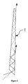
EP-A1-663600 (Nitto Jushi - Light emitted from the fluorescent tube over a range of directions enters the wedge through its thick end, and then propagates along the axis of taper by total internal reflection off the wedge/air interfaces, as shown in
Figure 1 . Because the waveguide is tapered, i. e. its faces are not quite parallel, each time a ray reflects off one side of the wedge, the ray's angle relative to the normal of the opposite side decreases. Eventually the critical angle is reached and the ray emerges into air. Unless they have been scattered, rays emerge from the wedge in a direction close to the plane of the wedge/air interface. A prismatic film is therefore often placed over the surface of the wedge in order to deflect the rays so that their average direction is perpendicular to the wedge/air interface. - The material out of which the wedge is made is often designed so that it slightly scatters light. The effect is that the direction of light which emerges from the wedge is diffuse so that the image on the liquid-crystal panel can be seen over a wide field of view. One thus obtains a uniform illumination.
- If an eye follows the image of a ball as it moves across a screen then, in order to avoid blur, the image of the ball should shift by one pixel every time the centre of attention of the eye shifts by one pixel. However, the moving image on a video display is made of still pictures called frames which are renewed at a set rate, namely every sixtieth of a second. Suppose that the image of a moving ball is being displayed, and that the image shifts ten pixels between each frame. At the start of each frame, the image of the ball coincides instantaneously with the centre of attention of the eye, but with each tenth of a frame period the centre of attention of the eye shifts by one pixel whereas the image of the ball remains where it is. The image of the ball therefore becomes blurred by up to ten pixel widths.
- Cathode ray tubes avoid blur because pixels are pulsed, so that the eye only sees the image of the ball at the start of each frame, or when the pixels are addressed, when the image coincides with the centre of attention of the eye. The eye sees nothing further until the image again coincides with the centre of attention of the eye, and the dark period in between is imperceptible because the eye cannot detect flicker at periods of a sixtieth of a second. One way of eliminating blur in a liquid-crystal display is to configure the liquid crystal so that it behaves like a cathode ray tube by relaxing into a dark state soon after being addressed.
- However, blocking light for large parts of the duty cycle wastes power. Another way of eliminating blur, as used in video projectors, is to scan illumination across the liquid- crystal display, but this requires bulk optic systems which are acceptable in video projectors but unacceptable within the flat form factor that makes liquid-crystal displays so attractive.
-
US patent 6,448,951 B1 claim 1. -
PCT publication WO2001/72037 - "Improved Motion-Picture Quality of AM-LCDs Using Scanning Backlight", N.Fisekovic, Asia Display 2001 discloses a method of reducing motion blur of LCD displays by scanning the backlight. Embodiments utilising independently controlled lamps and LED segmented side-lights are disclosed.
- This invention aims to provide a flat-panel display having a scanning illuminator which comprises a transparent wedge, and means for scanning the direction of light injected into the thick end of the wedge.
- There is provided a flat-panel display, comprising an illuminator and a flat-panel light modulator, the illuminator comprising a tapered slab waveguide co-extensive with the flat-panel light modulator, a light source arranged to inject light into a thick-end of the waveguide so that it propagates towards the thin end of the waveguide and emerges over the face of the waveguide at a point dependent on the angle of injection to the plane of the face of the waveguide, the flat-panel light modulator being located over the display waveguide for modulating light emerging from the face of the waveguide; and means for scanning the light injected into the said edge, the scanning means is adapted to inject light at varying angles relative to the plane of the waveguide, characterised in that the light source comprises addressable rows of LEDs, each row arranged to inject light at a different range of angles to the plane of the face of the waveguide such that light from each row of LEDs emerges over different areas of the face of the waveguide, and the scanning means includes a circuit for addressing these rows synchronised with a row-addressing circuit of the flat-panel light modulator.
- A selection of optional features of the invention are set out in the dependent claims.
- To aid understanding a specific embodiment of the invention will be given by way of example, referring to the accompanying drawings, in which:
-
Figure 1 shows how the angle at which light is injected into a wedge alters the position at which the light emerges; -
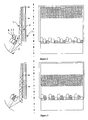
Figure 2 shows in side and front views how three lines of light-emitting diodes can be placed at different positions within the focal plane of a mirror so that each illuminates a different segment of the liquid-crystal display; -
Figure 3 is the same asFigure 2 but shows how the screen is illuminated a third of a frame later; -
Figure 4 is the same asFigure 2 but shows how the screen is illuminated two-thirds of a frame later; and -
Figure 5 shows in side and front views how a pair of wedges with shared thick ends can be used to direct light from three lines of light-emitting diodes to different areas behind a liquid-crystal panel. - As shown in
Figure 2 , a wedge-shaped, generally flatrectangular waveguide 1, which is entirely transparent and free of scattering inclusions, has its thick end, here at the bottom edge of the display, illuminated bylinear LED arrays cylindrical mirror 5. Each array consists of a row of LEDs of diameter about 5 mm, extending over the width of the display, which may be perhaps 30-100 cm. - The parallel light reflected off the mirror enters the thick end 10 of the wedge, which is bevelled so as to be roughly perpendicular to the incoming light, and bounces towards the thin end at ever shallower angles until it escapes, at a position determined by its angle of input. The steeper the angle of input, the earlier the light escapes.
- This principle is described in
EP-A1-663 600 (Nitto Jushi - This backlight assembly is used for a standard liquid- crystal display as follows. Once the top third of a frame has been written to the liquid-crystal display, the
first LED array 2 is illuminated. Light from this array is collimated into a set of angles which, after injection into the thick end of thewedge 1, go on to emerge from the top third of thewedge 1. Here the rays should be bent to the normal by a sheet ofprismatic film 6 and diffused, either before or after passing through the liquid-crystal display 7. - Once the centre third of the frame has been written to the liquid-crystal display, the
first LED array 2 is switched off and thesecond LED array 3 is switched on, as shown inFigure 3 . Light from thesecond LED array 3 is collimated into an adjacent set of angles which, after injection into the thick end of the wedge, go on to emerge from the centre of the wedge. - Lastly, once the bottom third of the frame has been written to the liquid-crystal display, the
middle LED array 3 is switched off and thethird LED array 4 is switched on so as to illuminate the bottom third of the liquid-crystal display. Simultaneously to this, the top third of the next frame will begin to be written to the top third of the liquid-crystal panel, and so on. This is shown inFigure 4 . - The controller for the LEDs is synchronised with that of the display so that each
row - Colour pictures require red, green and blue LED's, and it is conventional to interleave these in order to mix light of different colours before it reaches the liquid-crystal display. Furthermore, it is desirable generally to extend the thick end of the wedge beyond the base of the liquid crystal display so that there is a length over which mixing can take place, and so that the illumination is uniformly white at the base of the liquid-crystal panel and beyond.
- This extended section may need to be longer with the scanning-illumination scheme because LED's illuminating a particular region of the liquid-crystal panel at a particular wavelength will be more widely spaced than is conventional.
- If necessary, the extended section can be folded behind the liquid-crystal panel with prisms, so the extra length of the extended section does not create an unacceptable change in form factor.
- The cylindrical mirror is a slightly bulky element and it may be advantageous to exchange it for a second
short wedge 8 which acts as an input element for theillumination wedge 1 as shown inFigure 5 . Theinput wedge 8 acts in reverse, so that light injected near the tip ofwedge 8 fromLED 2 forms rays with a shallow angle at the interface betweeninput wedge 8 anddisplay wedge 1, and therefore emerges near the tip of thedisplay wedge 1, whereas light injected near the base of theinput wedge 8 forms rays with a steep angle at the interface between that wedge and thedisplay wedge 1, so the light emerges near the base of the display. - In the example described the scanning of the illumination is vertical. This is preferred because the scanning of the display is also vertical, i. e. row by row, but a division in the horizontal direction is conceivable.
- LEDs are also preferred as light sources because they switch on and off fast, but other sources could be used.
- The example also uses geometrically tapered wedge-shaped waveguides, but the same effect could be achieved with "optically tapered" waveguides, made for instance using GRIN techniques. For convenience such waveguides are referred to as "tapered".
Claims (5)
- A flat-panel display, comprising an illuminator and a flat-panel light modulator,
the illuminator comprising a tapered slab waveguide (1) having a light exit face co-extensive with the flat-panel light modulator, a light source (2-4) arranged to inject light into a thick-end of the waveguide (1) so that it propagates towards the thin end of the waveguide (1) and emerges over the face of the waveguide (1) at a point dependent on the angle of injection relative to the plane of the light exit face of the waveguide (1) at a point dependent on the angle of injection relative to the plane of the light exit face of the waveguide,
the flat-panel light modulator being located over the waveguide (1) for modulating light emerging from the light exit face of the waveguide (1); and means for scanning the light injected into the said edge,
the light source (2 - 4) comprising addressable rows of LEDs (2 - 4),
the scanning means including a circuit for addressing these rows synchronised with a row-addressing circuit of the flat-panel light modulator,
characterised in that
the scanning means is adapted to inject light at varying angles relative to the plane of the ligth exit face of the waveguide,
each row of LEDs (2-4) is arranged to inject light at a different range of angles relative to the plane of the light exit of the each row of LEDs (2-4) to inject light at a different range of angle relative to the plane of the light exit of the waveguide such that light from each row of LEDs (2 -4) emerges over different areas of the light exit face of the waveguide (1). - A flat-panel display according to claim 1, further comprising a cylindrical mirror (5) arranged to collimate the light from the LEDs (2 - 4) into the waveguide (1).
- A flat-panel display according to claim 1, further comprising a further waveguide (8) arranged to collimate light from the LEDs (2 - 4) into the waveguide (1).
- A flat-panel display according to any preceding claim further including a sheet (6) arranged to guide the emerging light towards the normal to the light exit face of the waveguide (1).
- A flat-panel display according to any preceding claim, in which the flat-panel light modulator is a liquid-crystal display.
Applications Claiming Priority (2)
| Application Number | Priority Date | Filing Date | Title |
|---|---|---|---|
| GBGB0313044.0A GB0313044D0 (en) | 2003-06-06 | 2003-06-06 | Flat panel scanning illuminator |
| PCT/GB2004/002386 WO2004109380A1 (en) | 2003-06-06 | 2004-06-04 | Scanning backlight for flat-panel display |
Publications (2)
| Publication Number | Publication Date |
|---|---|
| EP1634119A1 EP1634119A1 (en) | 2006-03-15 |
| EP1634119B1 true EP1634119B1 (en) | 2012-08-08 |
Family
ID=9959463
Family Applications (1)
| Application Number | Title | Priority Date | Filing Date |
|---|---|---|---|
| EP04736068A Expired - Fee Related EP1634119B1 (en) | 2003-06-06 | 2004-06-04 | Flat-panel display comprising a scanning backlight |
Country Status (7)
| Country | Link |
|---|---|
| US (2) | US7944428B2 (en) |
| EP (1) | EP1634119B1 (en) |
| JP (1) | JP4584916B2 (en) |
| KR (1) | KR101064798B1 (en) |
| CN (1) | CN100386687C (en) |
| GB (1) | GB0313044D0 (en) |
| WO (1) | WO2004109380A1 (en) |
Cited By (18)
| Publication number | Priority date | Publication date | Assignee | Title |
|---|---|---|---|---|
| WO2015200814A1 (en) * | 2014-06-26 | 2015-12-30 | Reald Inc. | Directional privacy display |
| US9678267B2 (en) | 2012-05-18 | 2017-06-13 | Reald Spark, Llc | Wide angle imaging directional backlights |
| US9709723B2 (en) | 2012-05-18 | 2017-07-18 | Reald Spark, Llc | Directional backlight |
| US9739928B2 (en) | 2013-10-14 | 2017-08-22 | Reald Spark, Llc | Light input for directional backlight |
| US9740034B2 (en) | 2013-10-14 | 2017-08-22 | Reald Spark, Llc | Control of directional display |
| US9835792B2 (en) | 2014-10-08 | 2017-12-05 | Reald Spark, Llc | Directional backlight |
| US9872007B2 (en) | 2013-06-17 | 2018-01-16 | Reald Spark, Llc | Controlling light sources of a directional backlight |
| US9910207B2 (en) | 2012-05-18 | 2018-03-06 | Reald Spark, Llc | Polarization recovery in a directional display device |
| US10054732B2 (en) | 2013-02-22 | 2018-08-21 | Reald Spark, Llc | Directional backlight having a rear reflector |
| US10228505B2 (en) | 2015-05-27 | 2019-03-12 | Reald Spark, Llc | Wide angle imaging directional backlights |
| US10321123B2 (en) | 2016-01-05 | 2019-06-11 | Reald Spark, Llc | Gaze correction of multi-view images |
| US10330843B2 (en) | 2015-11-13 | 2019-06-25 | Reald Spark, Llc | Wide angle imaging directional backlights |
| US10475418B2 (en) | 2015-10-26 | 2019-11-12 | Reald Spark, Llc | Intelligent privacy system, apparatus, and method thereof |
| US10634840B2 (en) | 2015-04-13 | 2020-04-28 | Reald Spark, Llc | Wide angle imaging directional backlights |
| US10712490B2 (en) | 2015-11-13 | 2020-07-14 | Reald Spark, Llc | Backlight having a waveguide with a plurality of extraction facets, array of light sources, a rear reflector having reflective facets and a transmissive sheet disposed between the waveguide and reflector |
| US11287878B2 (en) | 2012-05-18 | 2022-03-29 | ReaID Spark, LLC | Controlling light sources of a directional backlight |
| US11821602B2 (en) | 2020-09-16 | 2023-11-21 | Reald Spark, Llc | Vehicle external illumination device |
| US11966049B2 (en) | 2023-07-21 | 2024-04-23 | Reald Spark, Llc | Pupil tracking near-eye display |
Families Citing this family (175)
| Publication number | Priority date | Publication date | Assignee | Title |
|---|---|---|---|---|
| KR101167745B1 (en) * | 2004-07-27 | 2012-07-23 | 돌비 레버러토리즈 라이쎈싱 코오포레이션 | Parallax-reducing, luminance-preserving diffuser |
| US9282335B2 (en) * | 2005-03-15 | 2016-03-08 | Hewlett-Packard Development Company, L.P. | System and method for coding image frames |
| GB0522968D0 (en) | 2005-11-11 | 2005-12-21 | Popovich Milan M | Holographic illumination device |
| WO2007072360A1 (en) * | 2005-12-21 | 2007-06-28 | Koninklijke Philips Electronics N.V. | Backlight arrangement for highlighting a display panel |
| WO2007114818A1 (en) | 2006-03-31 | 2007-10-11 | Tte Technology, Inc. | Projection lens system and method |
| GB0718706D0 (en) | 2007-09-25 | 2007-11-07 | Creative Physics Ltd | Method and apparatus for reducing laser speckle |
| US7607814B2 (en) | 2006-05-24 | 2009-10-27 | 3M Innovative Properties Company | Backlight with symmetric wedge shaped light guide input portion with specular reflective surfaces |
| US7740387B2 (en) * | 2006-05-24 | 2010-06-22 | 3M Innovative Properties Company | Backlight wedge with side mounted light source |
| US7317182B2 (en) * | 2006-05-24 | 2008-01-08 | 3M Innovative Properties Company | Backlight wedge with encapsulated light source |
| US7660509B2 (en) | 2006-05-24 | 2010-02-09 | 3M Innovative Properties Company | Backlight asymmetric light input wedge |
| EP2027500A1 (en) * | 2006-05-26 | 2009-02-25 | TTE Technology, Inc. | Projection lens with exterior stop |
| KR100781362B1 (en) * | 2006-05-29 | 2007-11-30 | 삼성전자주식회사 | Back light unit and display apparatus having the same |
| US7759882B2 (en) * | 2006-07-31 | 2010-07-20 | Microsemi Corp.—Analog Mixed Signal Group Ltd. | Color control for scanning backlight |
| FR2906396A1 (en) * | 2006-09-26 | 2008-03-28 | Thomson Licensing Sas | ELECTROLUMINESCENT DIODE ELEMENT ASSEMBLY FOR BACKLIGHT DEVICE, BACKLIGHT DEVICE, AND BACKLIGHT SCREEN. |
| US7461962B2 (en) | 2007-01-22 | 2008-12-09 | Samsung Electronics Co., Ltd. | Backlight assembly, display device provided with the same, and method thereof |
| US7746517B2 (en) * | 2007-01-25 | 2010-06-29 | Lexmark International, Inc. | Image illumination and capture in a scanning device |
| US7548030B2 (en) * | 2007-03-29 | 2009-06-16 | Microsemi Corp.—Analog Mixed Signal Group Ltd. | Color control for dynamic scanning backlight |
| JP5587174B2 (en) * | 2007-04-17 | 2014-09-10 | コーニンクレッカ フィリップス エヌ ヴェ | Textile light emitting device |
| KR100877413B1 (en) * | 2007-06-04 | 2009-01-07 | 엘지전자 주식회사 | Backlight unit and liquid crystal display comprising the same |
| US7622697B2 (en) * | 2007-06-26 | 2009-11-24 | Microsemi Corp. - Analog Mixed Signal Group Ltd. | Brightness control for dynamic scanning backlight |
| WO2009028291A1 (en) * | 2007-08-24 | 2009-03-05 | Sharp Kabushiki Kaisha | Light guide unit, illuminating device and liquid crystal display device |
| WO2009113055A2 (en) * | 2008-03-13 | 2009-09-17 | Microsemi Corp. - Analog Mixed Signal Group, Ltd. | A color controller for a luminaire |
| TW201004477A (en) * | 2008-06-10 | 2010-01-16 | Microsemi Corp Analog Mixed Si | Color manager for backlight systems operative at multiple current levels |
| CN102273319B (en) | 2008-12-30 | 2016-09-14 | 皇家飞利浦电子股份有限公司 | Adjustable luminaire |
| US8324830B2 (en) * | 2009-02-19 | 2012-12-04 | Microsemi Corp.—Analog Mixed Signal Group Ltd. | Color management for field-sequential LCD display |
| US11726332B2 (en) | 2009-04-27 | 2023-08-15 | Digilens Inc. | Diffractive projection apparatus |
| US9335604B2 (en) | 2013-12-11 | 2016-05-10 | Milan Momcilo Popovich | Holographic waveguide display |
| DE102009028984B4 (en) | 2009-06-23 | 2014-05-08 | Seereal Technologies S.A. | Lighting unit for a direct-view display |
| CN102576115B (en) | 2009-06-23 | 2015-02-18 | 视瑞尔技术公司 | Lighting device for a direct viewing display |
| US11300795B1 (en) | 2009-09-30 | 2022-04-12 | Digilens Inc. | Systems for and methods of using fold gratings coordinated with output couplers for dual axis expansion |
| US10795160B1 (en) | 2014-09-25 | 2020-10-06 | Rockwell Collins, Inc. | Systems for and methods of using fold gratings for dual axis expansion |
| US8233204B1 (en) | 2009-09-30 | 2012-07-31 | Rockwell Collins, Inc. | Optical displays |
| US11320571B2 (en) | 2012-11-16 | 2022-05-03 | Rockwell Collins, Inc. | Transparent waveguide display providing upper and lower fields of view with uniform light extraction |
| TWI401507B (en) * | 2009-10-16 | 2013-07-11 | Au Optronics Corp | Backlight module and display apparatus |
| KR20110042528A (en) * | 2009-10-19 | 2011-04-27 | 삼성전자주식회사 | Backlight unit, display apparatus including the backlight unit and method of displaying thereof |
| KR20110050929A (en) * | 2009-11-09 | 2011-05-17 | 삼성전자주식회사 | Wearable display apparatus |
| US8659826B1 (en) | 2010-02-04 | 2014-02-25 | Rockwell Collins, Inc. | Worn display system and method without requiring real time tracking for boresight precision |
| US8477261B2 (en) | 2010-05-26 | 2013-07-02 | Microsoft Corporation | Shadow elimination in the backlight for a 3-D display |
| WO2012004016A1 (en) | 2010-07-06 | 2012-01-12 | Seereal Technologies S.A. | Beam divergence and various collimators for holographic or stereoscopic displays |
| US8793104B2 (en) * | 2010-08-12 | 2014-07-29 | Kuan Wen Chen | Flat panel display device |
| US8928567B2 (en) * | 2010-08-31 | 2015-01-06 | Sharp Laboratories Of America, Inc. | Switchable viewing angle display |
| US8947333B2 (en) * | 2010-08-31 | 2015-02-03 | Sharp Laboratories Of America, Inc. | Switchable viewing angle display with local dimming function |
| WO2012060266A1 (en) * | 2010-11-02 | 2012-05-10 | シャープ株式会社 | Light-control element, display device, and illumination device |
| WO2012060247A1 (en) * | 2010-11-02 | 2012-05-10 | シャープ株式会社 | Light-control element, display device, and illumination device |
| US9250448B2 (en) | 2010-11-19 | 2016-02-02 | Reald Inc. | Segmented directional backlight and related methods of backlight illumination |
| US20140041205A1 (en) | 2010-11-19 | 2014-02-13 | Reald Inc. | Method of manufacturing directional backlight apparatus and directional structured optical film |
| US8651726B2 (en) | 2010-11-19 | 2014-02-18 | Reald Inc. | Efficient polarized directional backlight |
| WO2012068532A2 (en) | 2010-11-19 | 2012-05-24 | Reald Inc. | Directional flat illuminators |
| US9201185B2 (en) | 2011-02-04 | 2015-12-01 | Microsoft Technology Licensing, Llc | Directional backlighting for display panels |
| KR101509370B1 (en) * | 2011-02-15 | 2015-04-07 | 미쓰비시덴키 가부시키가이샤 | Surface light source device and liquid crystal display device |
| DE102012100209B4 (en) | 2011-03-25 | 2022-10-27 | Seereal Technologies S.A. | Lighting device for a display or for a stereoscopic 3D display or for a holographic 3D display and display with a lighting device |
| US9274349B2 (en) | 2011-04-07 | 2016-03-01 | Digilens Inc. | Laser despeckler based on angular diversity |
| DE102012100212A1 (en) | 2011-06-06 | 2012-12-06 | Seereal Technologies S.A. | Method for manufacturing hologram of optical device for illuminating spatial light modulator for stereoscopic display, involves directing exposure light at holographic recording material through optical waveguide |
| US20140204455A1 (en) | 2011-08-24 | 2014-07-24 | Milan Momcilo Popovich | Wearable data display |
| US10670876B2 (en) | 2011-08-24 | 2020-06-02 | Digilens Inc. | Waveguide laser illuminator incorporating a despeckler |
| WO2013028944A1 (en) | 2011-08-24 | 2013-02-28 | Reald Inc. | Autostereoscopic display with a passive cycloidal diffractive waveplate |
| WO2016020630A2 (en) | 2014-08-08 | 2016-02-11 | Milan Momcilo Popovich | Waveguide laser illuminator incorporating a despeckler |
| US8634139B1 (en) | 2011-09-30 | 2014-01-21 | Rockwell Collins, Inc. | System for and method of catadioptric collimation in a compact head up display (HUD) |
| US9599813B1 (en) | 2011-09-30 | 2017-03-21 | Rockwell Collins, Inc. | Waveguide combiner system and method with less susceptibility to glare |
| US9366864B1 (en) | 2011-09-30 | 2016-06-14 | Rockwell Collins, Inc. | System for and method of displaying information without need for a combiner alignment detector |
| US9715067B1 (en) | 2011-09-30 | 2017-07-25 | Rockwell Collins, Inc. | Ultra-compact HUD utilizing waveguide pupil expander with surface relief gratings in high refractive index materials |
| US20140300709A1 (en) * | 2011-10-20 | 2014-10-09 | Seereal Technologies S.A. | Display device and method for representing a three-dimensional scene |
| US20150010265A1 (en) | 2012-01-06 | 2015-01-08 | Milan, Momcilo POPOVICH | Contact image sensor using switchable bragg gratings |
| WO2013104704A1 (en) | 2012-01-11 | 2013-07-18 | Seereal Technologies S.A. | Method for the production of a hologram for coupling illumination light out of a light guiding layer of an optical waveguide |
| DE102012100206A1 (en) | 2012-01-11 | 2013-07-11 | Seereal Technologies S.A. | Optical device for directing illumination light to spatial light modulator of display e.g. stereoscopic three dimensional (3D) display, has planar reflecting unit provided with reflection grating or dielectric mirror |
| US20140376207A1 (en) | 2012-01-11 | 2014-12-25 | Seereal Technologies S.A. | Optical apparatus for illuminating a pixel matrix and/or a controllable spatial light modulator for a display |
| US9354748B2 (en) | 2012-02-13 | 2016-05-31 | Microsoft Technology Licensing, Llc | Optical stylus interaction |
| US9426905B2 (en) | 2012-03-02 | 2016-08-23 | Microsoft Technology Licensing, Llc | Connection device for computing devices |
| US9870066B2 (en) | 2012-03-02 | 2018-01-16 | Microsoft Technology Licensing, Llc | Method of manufacturing an input device |
| US9360893B2 (en) | 2012-03-02 | 2016-06-07 | Microsoft Technology Licensing, Llc | Input device writing surface |
| USRE48963E1 (en) | 2012-03-02 | 2022-03-08 | Microsoft Technology Licensing, Llc | Connection device for computing devices |
| US8873227B2 (en) | 2012-03-02 | 2014-10-28 | Microsoft Corporation | Flexible hinge support layer |
| US9075566B2 (en) | 2012-03-02 | 2015-07-07 | Microsoft Technoogy Licensing, LLC | Flexible hinge spine |
| US9064654B2 (en) | 2012-03-02 | 2015-06-23 | Microsoft Technology Licensing, Llc | Method of manufacturing an input device |
| US8935774B2 (en) | 2012-03-02 | 2015-01-13 | Microsoft Corporation | Accessory device authentication |
| US9134807B2 (en) | 2012-03-02 | 2015-09-15 | Microsoft Technology Licensing, Llc | Pressure sensitive key normalization |
| US9523852B1 (en) | 2012-03-28 | 2016-12-20 | Rockwell Collins, Inc. | Micro collimator system and method for a head up display (HUD) |
| EP2842003B1 (en) | 2012-04-25 | 2019-02-27 | Rockwell Collins, Inc. | Holographic wide angle display |
| WO2013167864A1 (en) | 2012-05-11 | 2013-11-14 | Milan Momcilo Popovich | Apparatus for eye tracking |
| US20130300590A1 (en) | 2012-05-14 | 2013-11-14 | Paul Henry Dietz | Audio Feedback |
| JP6458950B2 (en) | 2012-05-18 | 2019-01-30 | リアルディー スパーク エルエルシー | Directional display device |
| US9350980B2 (en) | 2012-05-18 | 2016-05-24 | Reald Inc. | Crosstalk suppression in a directional backlight |
| US20130335821A1 (en) * | 2012-05-18 | 2013-12-19 | Reald Inc. | Source conditioning for imaging directional backlights |
| CN104380157B (en) * | 2012-05-18 | 2018-12-28 | 瑞尔D斯帕克有限责任公司 | Directional lighting waveguide assembly |
| US9188731B2 (en) | 2012-05-18 | 2015-11-17 | Reald Inc. | Directional backlight |
| US8947353B2 (en) | 2012-06-12 | 2015-02-03 | Microsoft Corporation | Photosensor array gesture detection |
| US9684382B2 (en) | 2012-06-13 | 2017-06-20 | Microsoft Technology Licensing, Llc | Input device configuration having capacitive and pressure sensors |
| US9459160B2 (en) | 2012-06-13 | 2016-10-04 | Microsoft Technology Licensing, Llc | Input device sensor configuration |
| US9256089B2 (en) | 2012-06-15 | 2016-02-09 | Microsoft Technology Licensing, Llc | Object-detecting backlight unit |
| US8917441B2 (en) | 2012-07-23 | 2014-12-23 | Reald Inc. | Observe tracking autostereoscopic display |
| US8964379B2 (en) | 2012-08-20 | 2015-02-24 | Microsoft Corporation | Switchable magnetic lock |
| CN104823097A (en) | 2012-10-02 | 2015-08-05 | 瑞尔D股份有限公司 | Stepped waveguide autostereoscopic display apparatus with reflective directional element |
| US8654030B1 (en) | 2012-10-16 | 2014-02-18 | Microsoft Corporation | Antenna placement |
| WO2014059624A1 (en) | 2012-10-17 | 2014-04-24 | Microsoft Corporation | Metal alloy injection molding protrusions |
| US9933684B2 (en) | 2012-11-16 | 2018-04-03 | Rockwell Collins, Inc. | Transparent waveguide display providing upper and lower fields of view having a specific light output aperture configuration |
| CN105008983B (en) | 2012-12-21 | 2018-08-07 | 瑞尔D斯帕克有限责任公司 | Super lens component for directional display |
| US10578499B2 (en) | 2013-02-17 | 2020-03-03 | Microsoft Technology Licensing, Llc | Piezo-actuated virtual buttons for touch surfaces |
| US9674413B1 (en) | 2013-04-17 | 2017-06-06 | Rockwell Collins, Inc. | Vision system and method having improved performance and solar mitigation |
| US10209517B2 (en) | 2013-05-20 | 2019-02-19 | Digilens, Inc. | Holographic waveguide eye tracker |
| US9727772B2 (en) | 2013-07-31 | 2017-08-08 | Digilens, Inc. | Method and apparatus for contact image sensing |
| US9244281B1 (en) | 2013-09-26 | 2016-01-26 | Rockwell Collins, Inc. | Display system and method using a detached combiner |
| WO2015073438A1 (en) | 2013-11-15 | 2015-05-21 | Reald Inc. | Directional backlights with light emitting element packages |
| US9448631B2 (en) | 2013-12-31 | 2016-09-20 | Microsoft Technology Licensing, Llc | Input device haptics and pressure sensing |
| US10732407B1 (en) | 2014-01-10 | 2020-08-04 | Rockwell Collins, Inc. | Near eye head up display system and method with fixed combiner |
| US9519089B1 (en) | 2014-01-30 | 2016-12-13 | Rockwell Collins, Inc. | High performance volume phase gratings |
| US9759854B2 (en) | 2014-02-17 | 2017-09-12 | Microsoft Technology Licensing, Llc | Input device outer layer and backlighting |
| US10120420B2 (en) | 2014-03-21 | 2018-11-06 | Microsoft Technology Licensing, Llc | Lockable display and techniques enabling use of lockable displays |
| US9244280B1 (en) | 2014-03-25 | 2016-01-26 | Rockwell Collins, Inc. | Near eye display system and method for display enhancement or redundancy |
| US10324733B2 (en) | 2014-07-30 | 2019-06-18 | Microsoft Technology Licensing, Llc | Shutdown notifications |
| US10359736B2 (en) | 2014-08-08 | 2019-07-23 | Digilens Inc. | Method for holographic mastering and replication |
| KR102262215B1 (en) * | 2014-09-01 | 2021-06-08 | 삼성전자주식회사 | Backlight unit and holographic display having the same |
| US9424048B2 (en) | 2014-09-15 | 2016-08-23 | Microsoft Technology Licensing, Llc | Inductive peripheral retention device |
| WO2016042283A1 (en) | 2014-09-19 | 2016-03-24 | Milan Momcilo Popovich | Method and apparatus for generating input images for holographic waveguide displays |
| US9715110B1 (en) | 2014-09-25 | 2017-07-25 | Rockwell Collins, Inc. | Automotive head up display (HUD) |
| US10088675B1 (en) | 2015-05-18 | 2018-10-02 | Rockwell Collins, Inc. | Turning light pipe for a pupil expansion system and method |
| EP3198192A1 (en) | 2014-09-26 | 2017-08-02 | Milan Momcilo Popovich | Holographic waveguide opticaltracker |
| GB2531721B (en) * | 2014-10-27 | 2021-02-24 | Flexenable Ltd | Imaging Device |
| DE102014226188A1 (en) * | 2014-12-17 | 2016-06-23 | Bayerische Motoren Werke Aktiengesellschaft | Communication between a vehicle and a road user in the vicinity of the vehicle |
| US10356383B2 (en) | 2014-12-24 | 2019-07-16 | Reald Spark, Llc | Adjustment of perceived roundness in stereoscopic image of a head |
| CN107873086B (en) | 2015-01-12 | 2020-03-20 | 迪吉伦斯公司 | Environmentally isolated waveguide display |
| US20180275402A1 (en) | 2015-01-12 | 2018-09-27 | Digilens, Inc. | Holographic waveguide light field displays |
| EP3248026B1 (en) | 2015-01-20 | 2019-09-04 | DigiLens Inc. | Holographic waveguide lidar |
| US9632226B2 (en) | 2015-02-12 | 2017-04-25 | Digilens Inc. | Waveguide grating device |
| US10459145B2 (en) | 2015-03-16 | 2019-10-29 | Digilens Inc. | Waveguide device incorporating a light pipe |
| RU2596062C1 (en) | 2015-03-20 | 2016-08-27 | Автономная Некоммерческая Образовательная Организация Высшего Профессионального Образования "Сколковский Институт Науки И Технологий" | Method for correction of eye image using machine learning and method of machine learning |
| WO2016156776A1 (en) | 2015-03-31 | 2016-10-06 | Milan Momcilo Popovich | Method and apparatus for contact image sensing |
| US11366316B2 (en) | 2015-05-18 | 2022-06-21 | Rockwell Collins, Inc. | Head up display (HUD) using a light pipe |
| US10247943B1 (en) | 2015-05-18 | 2019-04-02 | Rockwell Collins, Inc. | Head up display (HUD) using a light pipe |
| US10126552B2 (en) | 2015-05-18 | 2018-11-13 | Rockwell Collins, Inc. | Micro collimator system and method for a head up display (HUD) |
| US10416799B2 (en) | 2015-06-03 | 2019-09-17 | Microsoft Technology Licensing, Llc | Force sensing and inadvertent input control of an input device |
| US10222889B2 (en) | 2015-06-03 | 2019-03-05 | Microsoft Technology Licensing, Llc | Force inputs and cursor control |
| US10108010B2 (en) | 2015-06-29 | 2018-10-23 | Rockwell Collins, Inc. | System for and method of integrating head up displays and head down displays |
| CN108474945B (en) | 2015-10-05 | 2021-10-01 | 迪吉伦斯公司 | Waveguide display |
| WO2017083526A1 (en) | 2015-11-10 | 2017-05-18 | Reald Inc. | Distortion matching polarization conversion systems and methods thereof |
| US10598932B1 (en) | 2016-01-06 | 2020-03-24 | Rockwell Collins, Inc. | Head up display for integrating views of conformally mapped symbols and a fixed image source |
| US10061385B2 (en) | 2016-01-22 | 2018-08-28 | Microsoft Technology Licensing, Llc | Haptic feedback for a touch input device |
| KR20170088019A (en) * | 2016-01-22 | 2017-08-01 | 현대모비스 주식회사 | Lighting apparatus for an automobile |
| US10983340B2 (en) | 2016-02-04 | 2021-04-20 | Digilens Inc. | Holographic waveguide optical tracker |
| CN108780224B (en) | 2016-03-24 | 2021-08-03 | 迪吉伦斯公司 | Method and apparatus for providing a polarization selective holographic waveguide device |
| CN107290816B (en) | 2016-03-30 | 2020-04-24 | 中强光电股份有限公司 | Optical waveguide element and head-mounted display device having the same |
| CN109154717B (en) | 2016-04-11 | 2022-05-13 | 迪吉伦斯公司 | Holographic waveguide device for structured light projection |
| EP3458897A4 (en) | 2016-05-19 | 2019-11-06 | RealD Spark, LLC | Wide angle imaging directional backlights |
| US10425635B2 (en) | 2016-05-23 | 2019-09-24 | Reald Spark, Llc | Wide angle imaging directional backlights |
| CN109792826B (en) * | 2016-09-29 | 2021-11-16 | 昕诺飞控股有限公司 | Lighting device |
| WO2018102834A2 (en) | 2016-12-02 | 2018-06-07 | Digilens, Inc. | Waveguide device with uniform output illumination |
| US10401638B2 (en) | 2017-01-04 | 2019-09-03 | Reald Spark, Llc | Optical stack for imaging directional backlights |
| US10545346B2 (en) | 2017-01-05 | 2020-01-28 | Digilens Inc. | Wearable heads up displays |
| US10295824B2 (en) | 2017-01-26 | 2019-05-21 | Rockwell Collins, Inc. | Head up display with an angled light pipe |
| CN108445573B (en) * | 2017-02-16 | 2023-06-30 | 中强光电股份有限公司 | Optical waveguide element and display device |
| EP3607387A4 (en) | 2017-04-03 | 2020-11-25 | RealD Spark, LLC | Segmented imaging directional backlights |
| US10303030B2 (en) | 2017-05-08 | 2019-05-28 | Reald Spark, Llc | Reflective optical stack for privacy display |
| WO2018208619A1 (en) | 2017-05-08 | 2018-11-15 | Reald Spark, Llc | Optical stack for directional display |
| US10126575B1 (en) | 2017-05-08 | 2018-11-13 | Reald Spark, Llc | Optical stack for privacy display |
| EP4293574A3 (en) | 2017-08-08 | 2024-04-03 | RealD Spark, LLC | Adjusting a digital representation of a head region |
| TW201921060A (en) | 2017-09-15 | 2019-06-01 | 美商瑞爾D斯帕克有限責任公司 | Optical stack for switchable directional display |
| US20190108816A1 (en) * | 2017-10-10 | 2019-04-11 | Dell Products L.P. | Information Handling System Optical Narrow Bezel |
| JP7399084B2 (en) | 2017-10-16 | 2023-12-15 | ディジレンズ インコーポレイテッド | System and method for doubling the image resolution of pixelated displays |
| WO2019090246A1 (en) | 2017-11-06 | 2019-05-09 | Reald Spark, Llc | Privacy display apparatus |
| WO2019136476A1 (en) | 2018-01-08 | 2019-07-11 | Digilens, Inc. | Waveguide architectures and related methods of manufacturing |
| CN115356905A (en) | 2018-01-08 | 2022-11-18 | 迪吉伦斯公司 | System and method for holographic grating high throughput recording in waveguide cells |
| JP7291444B2 (en) | 2018-01-25 | 2023-06-15 | リアルディー スパーク エルエルシー | Display device and viewing angle control optical element |
| EP3743766A4 (en) | 2018-01-25 | 2021-12-22 | RealD Spark, LLC | Touch screen for privacy display |
| CN112088332A (en) | 2018-03-16 | 2020-12-15 | 迪吉伦斯公司 | Holographic waveguides including birefringence control and methods for their manufacture |
| WO2020023779A1 (en) | 2018-07-25 | 2020-01-30 | Digilens Inc. | Systems and methods for fabricating a multilayer optical structure |
| KR20210138609A (en) | 2019-02-15 | 2021-11-19 | 디지렌즈 인코포레이티드. | Method and apparatus for providing a holographic waveguide display using an integral grating |
| WO2020186113A1 (en) | 2019-03-12 | 2020-09-17 | Digilens Inc. | Holographic waveguide backlight and related methods of manufacturing |
| US11307347B2 (en) * | 2019-05-20 | 2022-04-19 | Facebook Technologies, Llc | Display illumination using a wedge waveguide |
| US11119343B2 (en) | 2019-05-20 | 2021-09-14 | Facebook Technologies, Llc | Optical waveguide beam splitter with polarization volume gratings for display |
| CN114207492A (en) | 2019-06-07 | 2022-03-18 | 迪吉伦斯公司 | Waveguide with transmission grating and reflection grating and method for producing the same |
| EP4004646A4 (en) | 2019-07-29 | 2023-09-06 | Digilens Inc. | Methods and apparatus for multiplying the image resolution and field-of-view of a pixelated display |
| CN114450608A (en) | 2019-08-29 | 2022-05-06 | 迪吉伦斯公司 | Vacuum Bragg grating and method of manufacture |
| US11726336B2 (en) | 2019-09-10 | 2023-08-15 | Meta Platforms Technologies, Llc | Active zonal display illumination using a chopped lightguide |
| US11391948B2 (en) | 2019-09-10 | 2022-07-19 | Facebook Technologies, Llc | Display illumination using a grating |
| US11592608B2 (en) | 2019-09-10 | 2023-02-28 | Meta Platforms Technologies, Llc | Switchable polarization retarder array for active zonal illumination of display |
| CN113129808B (en) * | 2019-12-31 | 2022-12-09 | Tcl科技集团股份有限公司 | Driving method and driving device of LED array and display device |
Family Cites Families (18)
| Publication number | Priority date | Publication date | Assignee | Title |
|---|---|---|---|---|
| US4978952A (en) * | 1989-02-24 | 1990-12-18 | Collimated Displays Incorporated | Flat screen color video display |
| JP3781441B2 (en) * | 1993-07-23 | 2006-05-31 | 康博 小池 | Light scattering light guide light source device and liquid crystal display device |
| US5613751A (en) * | 1995-06-27 | 1997-03-25 | Lumitex, Inc. | Light emitting panel assemblies |
| JP3653308B2 (en) * | 1995-08-01 | 2005-05-25 | 日東樹脂工業株式会社 | Surface light source device and liquid crystal display |
| JP3247643B2 (en) * | 1997-09-10 | 2002-01-21 | インターナショナル・ビジネス・マシーンズ・コーポレーション | Liquid crystal display device |
| JP3280307B2 (en) * | 1998-05-11 | 2002-05-13 | インターナショナル・ビジネス・マシーンズ・コーポレーション | Liquid crystal display |
| KR100398755B1 (en) * | 1998-06-02 | 2003-09-19 | 니폰샤신인사츠가부시키가이샤 | Front light-combined touch panel device |
| JP2000122053A (en) * | 1998-10-09 | 2000-04-28 | Hitachi Ltd | Reflection liquid crystal display device and movable type information terminal |
| GB2360603A (en) | 2000-03-20 | 2001-09-26 | Cambridge 3D Display Ltd | Planar optical waveguide and float glass process |
| JP3535445B2 (en) * | 2000-03-28 | 2004-06-07 | 株式会社東芝 | Display device |
| JP2002006766A (en) * | 2000-06-23 | 2002-01-11 | Sharp Corp | Display device |
| KR20020055596A (en) * | 2000-09-11 | 2002-07-09 | 요트.게.아. 롤페즈 | Display device |
| US6744416B2 (en) * | 2000-12-27 | 2004-06-01 | Casio Computer Co., Ltd. | Field sequential liquid crystal display apparatus |
| US7064740B2 (en) * | 2001-11-09 | 2006-06-20 | Sharp Laboratories Of America, Inc. | Backlit display with improved dynamic range |
| US6690349B2 (en) | 2001-11-09 | 2004-02-10 | Koninklijke Philips Electronics N.V. | Scrolling backlight system for LCD TV |
| JP2003187623A (en) * | 2001-12-18 | 2003-07-04 | Sharp Corp | Lighting device and display device using it |
| US6704071B2 (en) * | 2002-02-04 | 2004-03-09 | Wintek Corporation | Light guide capable of optically changing color of light |
| US6808281B2 (en) * | 2002-12-14 | 2004-10-26 | Quanta Display Incorporation | Backlight module having concave struture |
-
2003
- 2003-06-06 GB GBGB0313044.0A patent/GB0313044D0/en not_active Ceased
-
2004
- 2004-06-04 US US10/559,891 patent/US7944428B2/en not_active Expired - Fee Related
- 2004-06-04 WO PCT/GB2004/002386 patent/WO2004109380A1/en active Application Filing
- 2004-06-04 EP EP04736068A patent/EP1634119B1/en not_active Expired - Fee Related
- 2004-06-04 JP JP2006508395A patent/JP4584916B2/en not_active Expired - Fee Related
- 2004-06-04 CN CNB2004800157892A patent/CN100386687C/en not_active Expired - Fee Related
- 2004-06-04 KR KR1020057022918A patent/KR101064798B1/en active IP Right Grant
-
2011
- 2011-04-12 US US13/084,551 patent/US8581831B2/en not_active Expired - Fee Related
Cited By (26)
| Publication number | Priority date | Publication date | Assignee | Title |
|---|---|---|---|---|
| US9910207B2 (en) | 2012-05-18 | 2018-03-06 | Reald Spark, Llc | Polarization recovery in a directional display device |
| US9678267B2 (en) | 2012-05-18 | 2017-06-13 | Reald Spark, Llc | Wide angle imaging directional backlights |
| US9709723B2 (en) | 2012-05-18 | 2017-07-18 | Reald Spark, Llc | Directional backlight |
| US11287878B2 (en) | 2012-05-18 | 2022-03-29 | ReaID Spark, LLC | Controlling light sources of a directional backlight |
| US11681359B2 (en) | 2012-05-18 | 2023-06-20 | Reald Spark, Llc | Controlling light sources of a directional backlight |
| US10175418B2 (en) | 2012-05-18 | 2019-01-08 | Reald Spark, Llc | Wide angle imaging directional backlights |
| US10054732B2 (en) | 2013-02-22 | 2018-08-21 | Reald Spark, Llc | Directional backlight having a rear reflector |
| US9872007B2 (en) | 2013-06-17 | 2018-01-16 | Reald Spark, Llc | Controlling light sources of a directional backlight |
| US9740034B2 (en) | 2013-10-14 | 2017-08-22 | Reald Spark, Llc | Control of directional display |
| US9739928B2 (en) | 2013-10-14 | 2017-08-22 | Reald Spark, Llc | Light input for directional backlight |
| US10488578B2 (en) | 2013-10-14 | 2019-11-26 | Reald Spark, Llc | Light input for directional backlight |
| WO2015200814A1 (en) * | 2014-06-26 | 2015-12-30 | Reald Inc. | Directional privacy display |
| US11067736B2 (en) | 2014-06-26 | 2021-07-20 | Reald Spark, Llc | Directional privacy display |
| US9835792B2 (en) | 2014-10-08 | 2017-12-05 | Reald Spark, Llc | Directional backlight |
| US10634840B2 (en) | 2015-04-13 | 2020-04-28 | Reald Spark, Llc | Wide angle imaging directional backlights |
| US11061181B2 (en) | 2015-04-13 | 2021-07-13 | Reald Spark, Llc | Wide angle imaging directional backlights |
| US10228505B2 (en) | 2015-05-27 | 2019-03-12 | Reald Spark, Llc | Wide angle imaging directional backlights |
| US11030981B2 (en) | 2015-10-26 | 2021-06-08 | Reald Spark, Llc | Intelligent privacy system, apparatus, and method thereof |
| US10475418B2 (en) | 2015-10-26 | 2019-11-12 | Reald Spark, Llc | Intelligent privacy system, apparatus, and method thereof |
| US10712490B2 (en) | 2015-11-13 | 2020-07-14 | Reald Spark, Llc | Backlight having a waveguide with a plurality of extraction facets, array of light sources, a rear reflector having reflective facets and a transmissive sheet disposed between the waveguide and reflector |
| US11067738B2 (en) | 2015-11-13 | 2021-07-20 | Reald Spark, Llc | Surface features for imaging directional backlights |
| US10330843B2 (en) | 2015-11-13 | 2019-06-25 | Reald Spark, Llc | Wide angle imaging directional backlights |
| US10750160B2 (en) | 2016-01-05 | 2020-08-18 | Reald Spark, Llc | Gaze correction of multi-view images |
| US10321123B2 (en) | 2016-01-05 | 2019-06-11 | Reald Spark, Llc | Gaze correction of multi-view images |
| US11821602B2 (en) | 2020-09-16 | 2023-11-21 | Reald Spark, Llc | Vehicle external illumination device |
| US11966049B2 (en) | 2023-07-21 | 2024-04-23 | Reald Spark, Llc | Pupil tracking near-eye display |
Also Published As
| Publication number | Publication date |
|---|---|
| GB0313044D0 (en) | 2003-07-09 |
| JP4584916B2 (en) | 2010-11-24 |
| EP1634119A1 (en) | 2006-03-15 |
| CN1802598A (en) | 2006-07-12 |
| US20110187293A1 (en) | 2011-08-04 |
| KR101064798B1 (en) | 2011-09-14 |
| KR20060023134A (en) | 2006-03-13 |
| US8581831B2 (en) | 2013-11-12 |
| JP2006527389A (en) | 2006-11-30 |
| US20060132423A1 (en) | 2006-06-22 |
| WO2004109380A1 (en) | 2004-12-16 |
| CN100386687C (en) | 2008-05-07 |
| US7944428B2 (en) | 2011-05-17 |
Similar Documents
| Publication | Publication Date | Title |
|---|---|---|
| EP1634119B1 (en) | Flat-panel display comprising a scanning backlight | |
| US6559827B1 (en) | Display assembly | |
| US8723779B2 (en) | Tiled optical fiber display | |
| US9395578B2 (en) | Illumination unit, display, and electronic apparatus | |
| KR100702904B1 (en) | Plane light source and liquid crystal display device using the plane light source | |
| EP1211551A2 (en) | Color isolated backlight for an LCD | |
| TWI376549B (en) | Surface light source which selectively irradiates two linearly polarized light beams in polarized states different from each other and liquid crystal display apparatus using the same | |
| GB2448029A (en) | Focused illumination LCD with backlight emitting discrete colours of light | |
| EP1640787B1 (en) | Display | |
| JP4692040B2 (en) | Liquid crystal display | |
| US20060038769A1 (en) | Display apparatus with scanning backlight | |
| JP4483233B2 (en) | Surface light source and liquid crystal display device | |
| CA2555375C (en) | Tiled optical fiber display | |
| Käläntar et al. | 36.3: Late‐News Paper: Spatio‐Temporal Scanning Backlight for Color‐Field Sequential Optically Compensated Bend Liquid‐Crystal Display | |
| JP4421575B2 (en) | Display device | |
| JP5077447B2 (en) | Display device for stereoscopic image projection | |
| JP5397334B2 (en) | Driving method of display device | |
| EP1552327A1 (en) | Backlight and display utilising same | |
| KR101704034B1 (en) | A backlight unit, method for driving the backlight unit and display apparatus thereof | |
| KR20020032989A (en) | Large Size LCD with Tiled LC Panels |
Legal Events
| Date | Code | Title | Description |
|---|---|---|---|
| PUAI | Public reference made under article 153(3) epc to a published international application that has entered the european phase |
Free format text: ORIGINAL CODE: 0009012 |
|
| 17P | Request for examination filed |
Effective date: 20051229 |
|
| AK | Designated contracting states |
Kind code of ref document: A1 Designated state(s): DE FR GB NL |
|
| DAX | Request for extension of the european patent (deleted) | ||
| RBV | Designated contracting states (corrected) |
Designated state(s): DE FR GB NL |
|
| 17Q | First examination report despatched |
Effective date: 20080806 |
|
| GRAP | Despatch of communication of intention to grant a patent |
Free format text: ORIGINAL CODE: EPIDOSNIGR1 |
|
| RTI1 | Title (correction) |
Free format text: FLAT-PANEL DISPLAY COMPRISING A SCANNING BACKLIGHT |
|
| GRAS | Grant fee paid |
Free format text: ORIGINAL CODE: EPIDOSNIGR3 |
|
| GRAA | (expected) grant |
Free format text: ORIGINAL CODE: 0009210 |
|
| AK | Designated contracting states |
Kind code of ref document: B1 Designated state(s): DE FR GB NL |
|
| REG | Reference to a national code |
Ref country code: GB Ref legal event code: FG4D |
|
| REG | Reference to a national code |
Ref country code: NL Ref legal event code: T3 |
|
| REG | Reference to a national code |
Ref country code: DE Ref legal event code: R096 Ref document number: 602004038823 Country of ref document: DE Effective date: 20121011 |
|
| PLBE | No opposition filed within time limit |
Free format text: ORIGINAL CODE: 0009261 |
|
| STAA | Information on the status of an ep patent application or granted ep patent |
Free format text: STATUS: NO OPPOSITION FILED WITHIN TIME LIMIT |
|
| 26N | No opposition filed |
Effective date: 20130510 |
|
| REG | Reference to a national code |
Ref country code: DE Ref legal event code: R097 Ref document number: 602004038823 Country of ref document: DE Effective date: 20130510 |
|
| REG | Reference to a national code |
Ref country code: FR Ref legal event code: PLFP Year of fee payment: 13 |
|
| REG | Reference to a national code |
Ref country code: FR Ref legal event code: PLFP Year of fee payment: 14 |
|
| REG | Reference to a national code |
Ref country code: FR Ref legal event code: PLFP Year of fee payment: 15 |
|
| PGFP | Annual fee paid to national office [announced via postgrant information from national office to epo] |
Ref country code: NL Payment date: 20190515 Year of fee payment: 16 |
|
| PGFP | Annual fee paid to national office [announced via postgrant information from national office to epo] |
Ref country code: DE Payment date: 20190521 Year of fee payment: 16 |
|
| PGFP | Annual fee paid to national office [announced via postgrant information from national office to epo] |
Ref country code: FR Payment date: 20190510 Year of fee payment: 16 |
|
| PGFP | Annual fee paid to national office [announced via postgrant information from national office to epo] |
Ref country code: GB Payment date: 20190529 Year of fee payment: 16 |
|
| REG | Reference to a national code |
Ref country code: DE Ref legal event code: R082 Ref document number: 602004038823 Country of ref document: DE |
|
| REG | Reference to a national code |
Ref country code: GB Ref legal event code: 732E Free format text: REGISTERED BETWEEN 20200917 AND 20200923 Ref country code: NL Ref legal event code: PD Owner name: MICROSOFT TECHNOLOGY LICENSING, LLC; US Free format text: DETAILS ASSIGNMENT: CHANGE OF OWNER(S), ASSIGNMENT; FORMER OWNER NAME: CAMBRIDGE FLAT PROJECTION DISPLAYS LIMITED Effective date: 20200921 |
|
| REG | Reference to a national code |
Ref country code: DE Ref legal event code: R119 Ref document number: 602004038823 Country of ref document: DE |
|
| REG | Reference to a national code |
Ref country code: NL Ref legal event code: MM Effective date: 20200701 |
|
| REG | Reference to a national code |
Ref country code: DE Ref legal event code: R081 Ref document number: 602004038823 Country of ref document: DE Owner name: MICROSOFT TECHNOLOGY LICENSING LLC, REDMOND, US Free format text: FORMER OWNER: CAMBRIDGE FLAT PROJECTION DISPLAYS LTD., FENSTANTON, CAMBRIDGESHIRE, GB |
|
| GBPC | Gb: european patent ceased through non-payment of renewal fee |
Effective date: 20200604 |
|
| PG25 | Lapsed in a contracting state [announced via postgrant information from national office to epo] |
Ref country code: GB Free format text: LAPSE BECAUSE OF NON-PAYMENT OF DUE FEES Effective date: 20200604 Ref country code: FR Free format text: LAPSE BECAUSE OF NON-PAYMENT OF DUE FEES Effective date: 20200630 Ref country code: NL Free format text: LAPSE BECAUSE OF NON-PAYMENT OF DUE FEES Effective date: 20200701 |
|
| PG25 | Lapsed in a contracting state [announced via postgrant information from national office to epo] |
Ref country code: DE Free format text: LAPSE BECAUSE OF NON-PAYMENT OF DUE FEES Effective date: 20210101 |