US9906187B2 - Window assembly and a method regarding the same - Google Patents
Window assembly and a method regarding the same Download PDFInfo
- Publication number
- US9906187B2 US9906187B2 US14/986,897 US201614986897A US9906187B2 US 9906187 B2 US9906187 B2 US 9906187B2 US 201614986897 A US201614986897 A US 201614986897A US 9906187 B2 US9906187 B2 US 9906187B2
- Authority
- US
- United States
- Prior art keywords
- assembly
- window assembly
- mounting assembly
- glass unit
- mounting
- Prior art date
- Legal status (The legal status is an assumption and is not a legal conclusion. Google has not performed a legal analysis and makes no representation as to the accuracy of the status listed.)
- Expired - Fee Related
Links
Images




Classifications
-
- H—ELECTRICITY
- H02—GENERATION; CONVERSION OR DISTRIBUTION OF ELECTRIC POWER
- H02S—GENERATION OF ELECTRIC POWER BY CONVERSION OF INFRARED RADIATION, VISIBLE LIGHT OR ULTRAVIOLET LIGHT, e.g. USING PHOTOVOLTAIC [PV] MODULES
- H02S20/00—Supporting structures for PV modules
- H02S20/20—Supporting structures directly fixed to an immovable object
- H02S20/22—Supporting structures directly fixed to an immovable object specially adapted for buildings
-
- E—FIXED CONSTRUCTIONS
- E06—DOORS, WINDOWS, SHUTTERS, OR ROLLER BLINDS IN GENERAL; LADDERS
- E06B—FIXED OR MOVABLE CLOSURES FOR OPENINGS IN BUILDINGS, VEHICLES, FENCES OR LIKE ENCLOSURES IN GENERAL, e.g. DOORS, WINDOWS, BLINDS, GATES
- E06B3/00—Window sashes, door leaves, or like elements for closing wall or like openings; Layout of fixed or moving closures, e.g. windows in wall or like openings; Features of rigidly-mounted outer frames relating to the mounting of wing frames
- E06B3/66—Units comprising two or more parallel glass or like panes permanently secured together
-
- E—FIXED CONSTRUCTIONS
- E06—DOORS, WINDOWS, SHUTTERS, OR ROLLER BLINDS IN GENERAL; LADDERS
- E06B—FIXED OR MOVABLE CLOSURES FOR OPENINGS IN BUILDINGS, VEHICLES, FENCES OR LIKE ENCLOSURES IN GENERAL, e.g. DOORS, WINDOWS, BLINDS, GATES
- E06B5/00—Doors, windows, or like closures for special purposes; Border constructions therefor
-
- E—FIXED CONSTRUCTIONS
- E06—DOORS, WINDOWS, SHUTTERS, OR ROLLER BLINDS IN GENERAL; LADDERS
- E06B—FIXED OR MOVABLE CLOSURES FOR OPENINGS IN BUILDINGS, VEHICLES, FENCES OR LIKE ENCLOSURES IN GENERAL, e.g. DOORS, WINDOWS, BLINDS, GATES
- E06B7/00—Special arrangements or measures in connection with doors or windows
- E06B7/28—Other arrangements on doors or windows, e.g. door-plates, windows adapted to carry plants, hooks for window cleaners
-
- E—FIXED CONSTRUCTIONS
- E06—DOORS, WINDOWS, SHUTTERS, OR ROLLER BLINDS IN GENERAL; LADDERS
- E06B—FIXED OR MOVABLE CLOSURES FOR OPENINGS IN BUILDINGS, VEHICLES, FENCES OR LIKE ENCLOSURES IN GENERAL, e.g. DOORS, WINDOWS, BLINDS, GATES
- E06B9/00—Screening or protective devices for wall or similar openings, with or without operating or securing mechanisms; Closures of similar construction
- E06B9/24—Screens or other constructions affording protection against light, especially against sunshine; Similar screens for privacy or appearance; Slat blinds
-
- F—MECHANICAL ENGINEERING; LIGHTING; HEATING; WEAPONS; BLASTING
- F24—HEATING; RANGES; VENTILATING
- F24S—SOLAR HEAT COLLECTORS; SOLAR HEAT SYSTEMS
- F24S25/00—Arrangement of stationary mountings or supports for solar heat collector modules
- F24S25/60—Fixation means, e.g. fasteners, specially adapted for supporting solar heat collector modules
- F24S25/63—Fixation means, e.g. fasteners, specially adapted for supporting solar heat collector modules for fixing modules or their peripheral frames to supporting elements
-
- H—ELECTRICITY
- H02—GENERATION; CONVERSION OR DISTRIBUTION OF ELECTRIC POWER
- H02S—GENERATION OF ELECTRIC POWER BY CONVERSION OF INFRARED RADIATION, VISIBLE LIGHT OR ULTRAVIOLET LIGHT, e.g. USING PHOTOVOLTAIC [PV] MODULES
- H02S30/00—Structural details of PV modules other than those related to light conversion
-
- E—FIXED CONSTRUCTIONS
- E06—DOORS, WINDOWS, SHUTTERS, OR ROLLER BLINDS IN GENERAL; LADDERS
- E06B—FIXED OR MOVABLE CLOSURES FOR OPENINGS IN BUILDINGS, VEHICLES, FENCES OR LIKE ENCLOSURES IN GENERAL, e.g. DOORS, WINDOWS, BLINDS, GATES
- E06B9/00—Screening or protective devices for wall or similar openings, with or without operating or securing mechanisms; Closures of similar construction
- E06B9/24—Screens or other constructions affording protection against light, especially against sunshine; Similar screens for privacy or appearance; Slat blinds
- E06B2009/2476—Solar cells
-
- Y—GENERAL TAGGING OF NEW TECHNOLOGICAL DEVELOPMENTS; GENERAL TAGGING OF CROSS-SECTIONAL TECHNOLOGIES SPANNING OVER SEVERAL SECTIONS OF THE IPC; TECHNICAL SUBJECTS COVERED BY FORMER USPC CROSS-REFERENCE ART COLLECTIONS [XRACs] AND DIGESTS
- Y02—TECHNOLOGIES OR APPLICATIONS FOR MITIGATION OR ADAPTATION AGAINST CLIMATE CHANGE
- Y02B—CLIMATE CHANGE MITIGATION TECHNOLOGIES RELATED TO BUILDINGS, e.g. HOUSING, HOUSE APPLIANCES OR RELATED END-USER APPLICATIONS
- Y02B10/00—Integration of renewable energy sources in buildings
- Y02B10/10—Photovoltaic [PV]
-
- Y—GENERAL TAGGING OF NEW TECHNOLOGICAL DEVELOPMENTS; GENERAL TAGGING OF CROSS-SECTIONAL TECHNOLOGIES SPANNING OVER SEVERAL SECTIONS OF THE IPC; TECHNICAL SUBJECTS COVERED BY FORMER USPC CROSS-REFERENCE ART COLLECTIONS [XRACs] AND DIGESTS
- Y02—TECHNOLOGIES OR APPLICATIONS FOR MITIGATION OR ADAPTATION AGAINST CLIMATE CHANGE
- Y02E—REDUCTION OF GREENHOUSE GAS [GHG] EMISSIONS, RELATED TO ENERGY GENERATION, TRANSMISSION OR DISTRIBUTION
- Y02E10/00—Energy generation through renewable energy sources
- Y02E10/40—Solar thermal energy, e.g. solar towers
- Y02E10/47—Mountings or tracking
-
- Y—GENERAL TAGGING OF NEW TECHNOLOGICAL DEVELOPMENTS; GENERAL TAGGING OF CROSS-SECTIONAL TECHNOLOGIES SPANNING OVER SEVERAL SECTIONS OF THE IPC; TECHNICAL SUBJECTS COVERED BY FORMER USPC CROSS-REFERENCE ART COLLECTIONS [XRACs] AND DIGESTS
- Y02—TECHNOLOGIES OR APPLICATIONS FOR MITIGATION OR ADAPTATION AGAINST CLIMATE CHANGE
- Y02E—REDUCTION OF GREENHOUSE GAS [GHG] EMISSIONS, RELATED TO ENERGY GENERATION, TRANSMISSION OR DISTRIBUTION
- Y02E10/00—Energy generation through renewable energy sources
- Y02E10/50—Photovoltaic [PV] energy
-
- Y—GENERAL TAGGING OF NEW TECHNOLOGICAL DEVELOPMENTS; GENERAL TAGGING OF CROSS-SECTIONAL TECHNOLOGIES SPANNING OVER SEVERAL SECTIONS OF THE IPC; TECHNICAL SUBJECTS COVERED BY FORMER USPC CROSS-REFERENCE ART COLLECTIONS [XRACs] AND DIGESTS
- Y02—TECHNOLOGIES OR APPLICATIONS FOR MITIGATION OR ADAPTATION AGAINST CLIMATE CHANGE
- Y02E—REDUCTION OF GREENHOUSE GAS [GHG] EMISSIONS, RELATED TO ENERGY GENERATION, TRANSMISSION OR DISTRIBUTION
- Y02E70/00—Other energy conversion or management systems reducing GHG emissions
- Y02E70/30—Systems combining energy storage with energy generation of non-fossil origin
Definitions
- the present disclosure is directed to window assemblies and methods regarding the same.
- Window assemblies can include electrochromic materials that can change their optical properties in response to the application of an electrical potential. Such a change can make glazings within the assemblies more or less transparent or more or less reflective.
- the window assemblies may be coupled to one or more electrical components and installation can be complicated due to the associated electrical components. A need exists to improve the design of the window assemblies and methods of fabricating and installing the window assemblies.
- FIG. 1 includes an illustration of a fully assembled window in accordance with an embodiment.
- FIG. 2 includes an illustration of a front view of a partially completed window assembly including an insulated glass unit and mounting brackets.
- FIGS. 3, 4, and 5 include illustrations of perspective, front, and top views, respectively, of the mounting brackets of FIG. 2 .
- FIG. 6 includes an illustration of a cross-sectional view of a portion of a mounting assembly.
- FIG. 7 includes an illustration of the partially completed window assembly after removably coupling the mounting assembly to the insulating glass unit.
- FIG. 8 includes an illustration of an enlarged portion of the view of the partially completed window assembly of FIG. 7 .
- FIG. 9 includes an illustration of a cross-sectional view of the IGU, mounting bracket, mounting assembly, fastener, and cover.
- FIG. 10 includes an illustration of a front view of the window assembly during packaging and shipping in accordance with an embodiment.
- FIG. 11 includes an illustration of a front view of the window assembly after installation into a frame.
- the terms “comprises,” “comprising,” “includes,” “including,” “has,” “having,” or any other variation thereof, are intended to cover a non-exclusive inclusion.
- a process, method, article, or apparatus that comprises a list of features is not necessarily limited only to those features but may include other features not expressly listed or inherent to such process, method, article, or apparatus.
- “or” refers to an inclusive-or and not to an exclusive-or. For example, a condition A or B is satisfied by any one of the following: A is true (or present) and B is false (or not present), A is false (or not present) and B is true (or present), and both A and B are true (or present).
- a window assembly can include an insulated glass unit, a mounting assembly moveably coupled to the insulated glass unit, and an electrical component secured to the mounting assembly.
- the window assembly can be in a pre-assembled state such that all component parts of the window assembly are coupled to one another. Such a pre-assembled state allows the window assembly to be packaged and shipped as a single unit. Thus, the likelihood of parts becoming separated or lost during packaging, shipping, or at the installation site can be significantly reduced or eliminated.
- a method can include securing an electrical component to a mounting assembly, coupling the mounting assembly to an insulated glass unit, and installing the insulating glass unit in a frame.
- the mounting assembly can be positioned in a final position and securely fastened into position. Covers over fasteners can help to keep the window aesthetically pleasing. Furthermore, any or all space between the mounting assembly and the frame can be reduced or even eliminated.
- FIG. 1 includes an illustration of an installed window assembly 10 that can include an insulated glass unit (IGU) 11 , a solar panel 12 , covers 13 , and end caps 14 installed within a frame 15 .
- the window assembly 10 is designed to allow an electrical component, for example, the solar panel 12 , to be adjusted after installation to abut or placed closer to the frame 15 .
- FIG. 2 includes an illustration of a partially completed window assembly including the IGU 11 and mounting brackets 21 .
- the IGU 11 can include glazings that are spaced apart from one another.
- Each of the glazings can include a glass, such as soda lime glass, borosilicate glass, float glass, or the like), or can include another transparent material, such as sapphire, spinel, aluminum oxide (AlON), or the like.
- Each glazing can be a single sheet of transparent material or a laminate.
- An electrochromic (EC) device can be located on a surface of one of the glazings or on a substrate that is attached to a counter substrate, which can be one of the glazings. In an embodiment, the EC device 100 is between glazings of the IGU 11 , as illustrated in FIG. 9 .
- the EC device can have its optical properties change in response to a change in of an electrical potential. Such a change can, make the IGU 11 more transparent, less transparent, more reflective, or less reflective.
- An EC device can include a counter electrode layer, an electrochromic layer, and an ionically conductive layer separating the counter electrode layer and the electrochromic layer.
- the EC device can further include two transparent conductive layers are substantially parallel to and in electrically coupled to the counter electrode layer and the electrochromic layer.
- Exemplary materials for the counter electrode layer, the electrochromic material layer, the ionically conductive layer and the conductive layers are described in United States Patent Publication No. 2008/0169185, which is incorporated herein by reference in its entirety. Such materials can be substantially transparent oxides or nitrides.
- an electrical potential is applied across the layered structure of the EC device, such as by connecting the respective conductive layers to a low voltage electrical source, ions, such as Li + ions in the counter electrode layer, flow from the counter electrode layer, through the ion conductor layer, and to the electrochromic layer.
- electrons flow from the counter electrode layer, through an external circuit to the electrochromic layer so as to maintain charge neutrality in the counter electrode layer and the electrochromic layer.
- the transfer of ions and electrons to the electrochromic layer causes the optical characteristics of the electrochromic layer, and optionally the counter electrode layer in a complementary EC device, to change.
- the EC device changes color, the transparency, or both the color and transparency of the EC device.
- the mounting brackets 21 can be secured to the IGU 11 using adhesive, screws, double sided tape, and nut and bolt assemblies). In a particular embodiment, a permanent construction adhesive is used. In another embodiment, the brackets 21 can be molded into the IGU 11 , such as a glazing of the IGU 11 , wherein such glazing is to be exposed to an outdoor environment. In a particular embodiment, the brackets 21 can provide an electrical connection between the solar panel 12 and an EC layer within the IGU 11 or another electrical component of the window assembly or in the frame 15 , or an environmental control system of a building.
- the environmental control system can include the heating, ventilation, and air conditioning (HVAC) system, an interior lighting system, another suitable control system, or any combination thereof.
- HVAC heating, ventilation, and air conditioning
- the brackets 21 include a material that is an insulator.
- the brackets 21 may include a metal or a metal alloy, such as copper, aluminum, nickel, brass, bronze, or the like, or may include a polymer, such as a polyvinyl compound, a polyurethane, a polyolefin, or the like.
- a polymer such as a polyvinyl compound, a polyurethane, a polyolefin, or the like.
- Such polymer may include additives or be coated to achieve a material that can withstand long-term exposure to outdoor conditions.
- brackets 21 The number, size, and placement of the brackets 21 is selected to allow sufficient mechanical support of a mounting assembly and anything secured to the mounting assembly, such as the solar panel 12 , cover 13 , fasteners (not illustrated in FIG. 1 or 2 ) or the like. As illustrated in the embodiment of FIG. 2 , three mounting brackets 21 are secured to the IGU 11 .
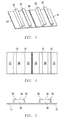
- FIGS. 3 to 5 include a perspective view, a front view (when installed), and a top view (when installed) of one of the mounting bracket 21 of the IGU 11 .
- the mounting bracket 21 includes features 32 that extend away from a body 31 of the mounting brackets 21 .
- the features 32 are used to couple the mounting assembly to the IGU 11 .
- the side of the body 31 opposite the features 32 is secured to or molded into the IGU 11 , and thus, the features 32 extend away from the IGU 11 when the mounting brackets 21 are secured or molded into the IGU 11 .
- Each pair of the features 32 define a channel 35 , and a slot 36 , which the space between the upper portions of the pair of features 32 and above the channel 35 .
- the features 32 can be used in conjunction with a fastener (not illustrated in FIGS. 3 to 5 ) used in fastening the mounting assembly to the mounting brackets 21 .
- An electrical component such as the solar panel, 12
- the electrical component can be secured to a mounting assembly 62 , as illustrated in FIG. 6 .
- the electrical component can be the solar panel 12 , a light sensor (that may or may not be part of the solar panel), a control unit, an energy storage unit, another suitable electrical component for use with the window assembly, or any combination thereof.
- the solar panel 12 can include a photovoltaic cell, another suitable device can that convert light or a temperature difference into energy, or any combination thereof.
- An exemplary solar panel that can be used is manufactured by China Solar Ltd. of ShenZhen City, China, model number KS-M33057G.
- the energy storage unit can be a battery, a capacitor, another suitable device capable of storing energy, or any combination thereof.
- the solar panel, light sensor, or both can be secured such that ambient light can reach an exposed surface.
- the solar panel 12 attached to the mounting assembly 62 via double sided tape (for example, VHB-brandTM tape manufactured by 3M Company of St. Paul, Minn., USA).
- double sided tape for example, VHB-brandTM tape manufactured by 3M Company of St. Paul, Minn., USA.
- other methods of attachment are also possible (for example, adhesive, nut and bolt assemblies, rivets, welding, or the like).
- appendages can extend over the top lip 44 and bottom lip 45 of the mounting assembly 62 to secure the solar panel 12 or other electrical component to the mounting assembly 62 .
- the appendages provide a releasable connection to the mounting assembly 62 . In this way, the solar panel 12 or other electrical component can be removed for replacement, repairs, or the like, as necessary.
- an electrical connection can be a polyimide flexible circuit 73 that extends from an edge of the solar panel 12 facing the mounting assembly 62 .
- the polyimide flexible circuit 73 can provide the electrical connection to the EC device, energy storage unit control unit, or other electrical component secured to the mounting assembly 62 or within the building.
- the control unit, the energy storage unit, and electrical connectors may not be visible and may be covered by a solar panel, light sensor, covers 13 , or another component.
- control unit can be coupled to the solar panel, light sensor, energy storage unit, EC device, or, after installation, an environmental control system for a building, such as any previously described, for such building in which the window assembly is installed.
- outside light conditions can be determined by the control unit in response to current of a solar panel, a signal from the light sensor, a temperature difference between inside and outside the building, or the like.
- the control unit can adjust the potential of the EC device to affect transmission of light or solar heat gain coefficient.
- the control unit can be used to control charging and discharging of the energy storage unit.
- the control unit may receive state information from the environmental control system or another source and control the EC device accordingly.
- control unit may allow a higher transmission, a higher solar heat gain coefficient, or both on a sunny cold day as compared to a sunny hot day.
- temperature difference between the ambient inside and outside of the building may be used.
- control unit can provide other functionality as needed or desired.
- skilled artisans will understand that the control unit may have its functionality tailored to a particular application as needed or desired. Thus, the functionality described is merely exemplary and does not limit the scope of the appended claims.
- FIG. 7 includes an illustration of the partially completed window assembly after a mounting assembly 62 is moveably coupled to the mounting brackets 21 .
- FIG. 8 includes an enlarged view of a portion of the partially completed window assembly to illustrate better a portion of the mounting assembly 62 .
- the solar panel 12 , another electrical component, or any combination thereof may be secured to the mounting assembly 62 before or after moveably coupling the mounting assembly 12 to the mounting brackets 21 . In the embodiment as illustrated in FIGS. 6 and 7 , the solar panel 12 , another electrical component, or any combination thereof is secured to the mounting assembly 62 before moveably coupling.
- the mounting assembly 62 can be generally in the form of a plate.
- the mounting assembly 62 can include a molded or extruded material, such as any of the materials as described with respect to the mounting brackets 21 .
- the mounting assembly 62 may include hardware, openings in the mounting assembly or other features to aid in securing electrical components, covers 13 , or other components to the mounting assembly 62 .
- the mounting assembly 62 defines openings 64 .
- the openings 64 can have a two-dimensional shape of a circle (not elongated), elongated circle (illustrated), ellipse, rectangle (that may or may not be a square), hexagon, or another polygonal shape.
- the elongated circle can allow for some lateral misalignment.
- the elongated circle may allow for expansion and contraction as the temperature changes.
- the mounting assembly 62 can have a circular opening in the middle for attachment to the center mounting bracket 21 , and elongated circular openings near the ends of the mounting assembly.
- the openings 64 may be formed before placing the mounting assembly 62 near the mounting brackets 21 .
- the locations of the slots of the mounting brackets may be marked on the mounting assembly 62 , and the openings 64 can be made at locations corresponding to the markings.
- the openings 64 can be drilled or punched.
- fasteners 66 allow the mounting assembly 62 to be moveable coupled to the IGU 11 .
- the mounting assembly 62 may include one or more openings for electrical connectors to be made between the electrical component(s) (secured to the mounting assembly 62 ) and the EC device within the IGU 11 , electrical connections within the building in which the window assembly will be installed, or any combination thereof.
- FIG. 9 includes an illustration of a cross-sectional view of a portion of the window assembly after the mounting assembly 62 is fastened to the mounting brackets 21 and the cover 13 is placed over the fastener 66 .
- an adhesive 82 couples the mounting bracket 21 to the IGU 11 .
- the fastener 66 can be a compression fastener, which is a fastener that uses compressive force to fasten.
- the fastener 66 can include a bolt, a screw (illustrated in FIG. 9 ), a cam lever, a bayonet connector, or another suitable fastener that can help to exert compressive force between the mounting assembly 62 and the mounting bracket 21 .
- the fastener can include a nut, a spring, or another suitable part to aid in compression.
- a washer 84 may be used to help spread the load of the compressive force or to help keep the fastener in place.
- the washer 84 can be a flat washer or a lock washer.
- the fastener 66 can include a stem that extends through the opening 64 in the mounting assembly 62 .
- the window assembly can further include an anti-rattle member that can reduce rattling and be disposed between the mounting assembly 62 and the IGU 11 .
- the anti-rattle member can be a compressive material, such as rubber or a polymer.
- the anti-rattle member can be in the form of an o-ring, a washer (such as washer 84 ), an interposer, or the like.
- the fastener 66 includes a screw 65 , and a stem 86 of the screw 65 is inserted through the opening 64 , and a washer 84 is placed around the stem, so that the mounting assembly 62 is disposed between the washer 64 and the head of the screw 65 .
- a nut 68 is placed within the channel 35 of the mounting bracket 21 , and the screw 65 is mated with the nut 68 .
- the cover 13 can be used to cover the fastening hardware and the mounting assembly 62 .
- the cover 13 can be a hinged cover (with a hinge 92 as illustrated), a snap-on cover, screw-on cover, or the like. If the cover 13 has not been previously attached to the mounting assembly 62 , it can be attached at this time. If it has been previously attached, the cover 13 can be moved to allow access to the opening 64 and to fasten the mounting assembly 62 to the mounting brackets 21 . After fastening, the cover 13 is placed over the fastener 66 .
- FIG. 10 includes an illustration of a front view of the window assembly in its state when shipped. Because the electrical components and mounting assembly are attached to the window assembly, the window assembly can be shipped as a single unit, fully pre-assembled. The mounting assembly 62 and electrical components do not need to be shipped separately or as different units within the same package. Thus, there is a lower likelihood that the IGU 11 will become separated from the mounting assembly 62 or corresponding electrical components before or at the time of installation. However, in another embodiment, the mounting brackets 21 , mounting assembly 62 , electrical components, or any combination thereof may be shipped as separate units in the same package or within different packages, should a customer so request.
- the package may be shipped a relatively short distance or a very long distance.
- the distance can be at least 11 km, at least 50 km, at least 110 km, or at least 500 km, and in another embodiment, the distance may be no greater than 90 million km, no greater than 9 million km, no greater than 25,000 km, or no greater than 9000 km, or no greater than 5000 km. In a particular embodiment, the distance is in a range of 11 km to 25,000 km, 50 km to 9000 km, or 110 km to 5000 km. If the window assembly will be used on Earth, the distance will likely be no greater than 25,000 km.
- the distance may be greater than 25,000 km, and, in many instances, will be no greater than 90 million km. Many times the fabrication facility and installation site are on the same continent, so the distance may be no greater than 9000 km or 5000 km. Special shipping precautions may not be required for the relatively shorter distances (less that 50 km or even less than 11 km).
- the window assembly 10 is installed within the frame 15 , as illustrated in FIG. 11 .
- the mounting assembly 62 extends along at least 70%, at least 80%, or at least 90% of the length of the closest member of the frame 15 .
- electrical connections may be made between the building's electrical system and any one or more of the electrical components of the window assembly 10 if needed or desired.
- wireless communication can be established between a transmitter or transceiver within the building and any one or more of the electrical components of the window assembly 10 .
- an inductive power source may be coupled to the control unit or an energy storage unit that drives the EC device of the window assembly 10 .
- the window assembly 10 may have self-contained electrical components that do not need a power or communications interface with the building's electrical system.
- a space 112 may exist between the solar panel 12 and frame 15 .
- the space 112 helps to compensate for varying tolerances associated with window framing systems.
- the space 112 may be reduced or eliminated after the window assembly 10 is installed within the frame 15 .
- the cover 13 is moved to expose the fasteners, such as previously described with respect to FIGS. 7 and 8 . If the covers 13 are hinged covers, the covers can be moved about the hinges. Otherwise, the covers 13 can be removed.
- the fasteners can be loosened and the mounting assembly 62 can be positioned to its final position. Typically, the mounting assembly 62 is moved closer to the frame 15 or an outer edge of the IGU 11 , wherein such outer edge is closest to the mounting assembly 62 .
- the mounting assembly 62 is moved such it abuts the frame 15 . In another embodiment, the mounting assembly 62 is moved closer to but remains spaced-apart from the frame 15 . Such a configuration may be useful if the coefficient of thermal expansion between the frame 15 and the mounting assembly 62 are significantly different, or if water drainage is a concern.
- the fasteners are tightened once the mounting assembly 62 is in its final position, and the covers 13 are used to cover the fasteners. If needed or desired, end caps 15 may be used to cover spaces between ends of the mounting assembly 62 and the frame 15 .
- the installed window assembly 10 with the positioned mounting assembly is illustrated in FIG. 1 .
- Embodiments described herein have benefits over conventional systems.
- the pre-assembly of the mounting assembly allows the IGU 11 and mounting assembly 62 and its corresponding electrical component to be shipped as a unit. This can reduce the likelihood of parts becoming separate or lost during shipment or at the installation site.
- the pre-assembly of the window assembly 10 allows the window assembly 10 to be installed more readily, as compared to a window assembly 10 if the mounting assembly 62 would have in a fixed, non-moveable position.
- the fasteners help to retain securely the mounting assembly 62 and the associated electronic component(s), so that parts are less likely to be separated or lost during shipping or at the installation site.
- the moveable coupling between the mounting assembly 62 and the mounting brackets 21 allow the window assembly to be installed and have a clean, professionally installed look. If the mounting assembly 62 would be fixed and not moveably coupled, the installation would be much more difficult as shims or other positioning members may be required during installation. Thus, the window assembly 10 allows installation to be easier as compared to a fixed position mounting assembly 62 .
- a window assembly comprising:
- a mounting assembly moveably coupled to the insulated glass unit
- a method comprising:
- Embodiment 5 further comprising:
- Embodiment 5 or 6 wherein positioning comprises moving the mounting assembly and electrical component toward the frame.
- Embodiment 10 furthering comprising moving the cover to expose the fastener before loosening and tightening the fastener.
- a distance between the first and second locations is at least 11 km, at least 50 km, at least 110 km, or at least 500 km.
- Embodiment 12 or 13 wherein the distance between the first and second locations is no greater than 90 million km, no greater than 9 million km, no greater than 25,000 km, or no greater than 9000 km, or no greater than 5000 km.
- a distance between the first and second locations is in a range of 11 km to 25,000 km, 50 km to 9000 km, or 110 km to 5000 km.
- the insulated glass unit comprises an electrochemical system.
- the electrical component comprises a control unit.
- the window assembly or method of any one of Embodiments 1 to 22, wherein the window assembly further comprises a control unit coupled to an electrochemical system, the electrical component, or both.
- the window assembly or method of Embodiment 32 further comprising adhesive, a screw, double sided tape, or a nut-and-bolt assembly that secures the mounting bracket to the insulating glass unit.
- the window assembly or method of any one of the preceding Embodiments, wherein the window assembly comprises at least 2, at least 3, at least 4, or at least 5 mounting brackets.
- the mounting assembly includes a plate.
- the mounting assembly includes an opening in a form of an elongated circle.
- the mounting assembly further includes another opening in a form of a circle that is not elongated and is closer to a center of the mounting assembly as compared to the opening in the form of the elongated circle.
Landscapes
- Engineering & Computer Science (AREA)
- Structural Engineering (AREA)
- Civil Engineering (AREA)
- Architecture (AREA)
- Thermal Sciences (AREA)
- Life Sciences & Earth Sciences (AREA)
- Sustainable Development (AREA)
- Sustainable Energy (AREA)
- Physics & Mathematics (AREA)
- Chemical & Material Sciences (AREA)
- Combustion & Propulsion (AREA)
- Mechanical Engineering (AREA)
- General Engineering & Computer Science (AREA)
- Electrochromic Elements, Electrophoresis, Or Variable Reflection Or Absorption Elements (AREA)
- Securing Of Glass Panes Or The Like (AREA)
- Photovoltaic Devices (AREA)
Priority Applications (1)
| Application Number | Priority Date | Filing Date | Title |
|---|---|---|---|
| US14/986,897 US9906187B2 (en) | 2015-01-06 | 2016-01-04 | Window assembly and a method regarding the same |
Applications Claiming Priority (2)
| Application Number | Priority Date | Filing Date | Title |
|---|---|---|---|
| US201562100328P | 2015-01-06 | 2015-01-06 | |
| US14/986,897 US9906187B2 (en) | 2015-01-06 | 2016-01-04 | Window assembly and a method regarding the same |
Publications (2)
| Publication Number | Publication Date |
|---|---|
| US20160197576A1 US20160197576A1 (en) | 2016-07-07 |
| US9906187B2 true US9906187B2 (en) | 2018-02-27 |
Family
ID=56291493
Family Applications (1)
| Application Number | Title | Priority Date | Filing Date |
|---|---|---|---|
| US14/986,897 Expired - Fee Related US9906187B2 (en) | 2015-01-06 | 2016-01-04 | Window assembly and a method regarding the same |
Country Status (4)
| Country | Link |
|---|---|
| US (1) | US9906187B2 (de) |
| EP (1) | EP3243104B1 (de) |
| JP (1) | JP2018505978A (de) |
| WO (1) | WO2016111918A1 (de) |
Cited By (1)
| Publication number | Priority date | Publication date | Assignee | Title |
|---|---|---|---|---|
| US10601362B2 (en) * | 2016-09-09 | 2020-03-24 | Pegasus Solar Inc. | Tile replacement solar mounting system |
Families Citing this family (5)
| Publication number | Priority date | Publication date | Assignee | Title |
|---|---|---|---|---|
| US10303035B2 (en) | 2009-12-22 | 2019-05-28 | View, Inc. | Self-contained EC IGU |
| WO2014032023A1 (en) | 2012-08-23 | 2014-02-27 | View, Inc. | Photonic-powered ec devices |
| US9906187B2 (en) | 2015-01-06 | 2018-02-27 | Sage Electrochromics, Inc. | Window assembly and a method regarding the same |
| US11320713B2 (en) | 2017-02-16 | 2022-05-03 | View, Inc. | Solar power dynamic glass for heating and cooling buildings |
| CN112290883A (zh) * | 2020-08-31 | 2021-01-29 | 北京双杰电气股份有限公司 | 一种光伏汇流装置 |
Citations (24)
| Publication number | Priority date | Publication date | Assignee | Title |
|---|---|---|---|---|
| US6001487A (en) | 1996-10-17 | 1999-12-14 | Saint-Gobain Vitrage | Glazing assembly having a thermally, electrically and/or electrochemically active system |
| US6055089A (en) | 1999-02-25 | 2000-04-25 | Minnesota Mining And Manufacturing Company | Photovoltaic powering and control system for electrochromic windows |
| US6119403A (en) * | 1998-12-23 | 2000-09-19 | Brose Fahrzeugteile Gmbh & Co. Kg, Coburg | Device for connecting a motor vehicle window pane to a window lifter |
| US6406090B1 (en) * | 1999-09-20 | 2002-06-18 | Meritor Light Vehicle Systems, Inc. | Self-powered solar sunroof |
| US20080009884A1 (en) | 2006-06-26 | 2008-01-10 | Wilson-Cook Medical Inc. | Handle for lithotripsy basket device |
| US20080169185A1 (en) | 2005-02-23 | 2008-07-17 | Sage Electrochromics, Inc. | Electrochromic devices and methods |
| US7455081B2 (en) * | 2003-03-12 | 2008-11-25 | Fasteners For Retail, Inc. | Holder for an electronic price label |
| US20090009982A1 (en) | 2006-04-14 | 2009-01-08 | Tom Whitney | Electrical component mounting assembly |
| US20090320896A1 (en) | 2008-06-25 | 2009-12-31 | Gerhardinger Peter F | Moisture resistant solar panel and method of making same |
| US20100096073A1 (en) | 2008-09-16 | 2010-04-22 | Adriani Paul M | Compression or arched mounting of solar panels |
| US7715201B2 (en) * | 2004-10-15 | 2010-05-11 | Rittal Gmbh & Co. Kg | Housing or frame-like holding element with an inscribed strip |
| US20100313501A1 (en) | 2009-06-10 | 2010-12-16 | Gangemi Ronald J | Roof mounting bracket for photovoltaic power generation system |
| US20110120528A1 (en) * | 2009-11-23 | 2011-05-26 | Pvt Solar, Inc. | Energy transfer module utilizing thermal power generated by solar panels |
| US20110167741A1 (en) | 2009-08-18 | 2011-07-14 | Kevin Surace | Methods and systems for retrofitting glass or insulated glass units of existing curtain wall systems for improved thermal performance |
| US20120194895A1 (en) | 2011-01-24 | 2012-08-02 | Sage Electrochromics, Inc. | Control system for electrochromic device |
| US20120317900A1 (en) | 2010-04-26 | 2012-12-20 | Guardian Industries Corp. | Multi-functional photovoltaic skylight and/or methods of making the same |
| WO2013090264A1 (en) | 2011-12-14 | 2013-06-20 | View, Inc. | Connectors for smart windows |
| US20130228989A1 (en) | 2012-03-02 | 2013-09-05 | Andrew J. Horst | Hubless wheel and related stroller |
| US20140003038A1 (en) * | 2012-07-02 | 2014-01-02 | Samsung Sdi Co., Ltd. | Lighting apparatus using solar cell |
| WO2014032023A1 (en) | 2012-08-23 | 2014-02-27 | View, Inc. | Photonic-powered ec devices |
| US20140157696A1 (en) | 2012-12-07 | 2014-06-12 | Quanta Technologies, Inc. | Air infiltration reduction system, insulating panel assembly, mounting assembly, and method of installing the same |
| WO2015200091A1 (en) | 2014-06-25 | 2015-12-30 | Sage Electrochromics, Inc. | Method of pre-attaching assemblies to an electrochromic glazing for accurate fit or registration after installation |
| US20160197220A1 (en) * | 2015-01-06 | 2016-07-07 | Sage Electrochromics, Inc. | Set of window assemblies and a method of fabricating the same |
| WO2016111918A1 (en) | 2015-01-06 | 2016-07-14 | Sage Electrochromics, Inc. | Window assembly and a method regarding the same |
Family Cites Families (12)
| Publication number | Priority date | Publication date | Assignee | Title |
|---|---|---|---|---|
| JPH02125195U (de) * | 1989-03-28 | 1990-10-16 | ||
| JP3047118U (ja) * | 1997-09-12 | 1998-03-31 | ジプロ株式会社 | 窓ガラスの日よけ板用止め具 |
| JP4025483B2 (ja) * | 2000-04-11 | 2007-12-19 | ティーオーエー株式会社 | 電子機器用筐体の取付け具 |
| KR100628981B1 (ko) * | 2004-01-03 | 2006-09-27 | 한국에너지기술연구원 | 열선이 구비된 복층유리 창호 |
| JP2006132206A (ja) * | 2004-11-05 | 2006-05-25 | Yasuo Yamakoshi | 窓用ディスプレイ装置 |
| US20090139562A1 (en) * | 2007-12-03 | 2009-06-04 | Donald Lee Thomas | Portable photovoltaic window system |
| JP2010163750A (ja) * | 2009-01-13 | 2010-07-29 | Panasonic Electric Works Co Ltd | 太陽電池パネルの取付け構造 |
| WO2012079159A1 (en) * | 2010-12-15 | 2012-06-21 | Switch Materials Inc. | Variable transmittance optical devices |
| JP2013069984A (ja) * | 2011-09-26 | 2013-04-18 | Nec Saitama Ltd | 装置取付具及び装置 |
| JP5869331B2 (ja) * | 2011-12-09 | 2016-02-24 | アーキヤマデ株式会社 | ソーラパネル取付方法 |
| JP5603891B2 (ja) * | 2012-02-16 | 2014-10-08 | フクビ化学工業株式会社 | 枠材および遮熱パネル |
| JP6190613B2 (ja) * | 2013-04-11 | 2017-08-30 | ケーファクトリー株式会社 | ソーラーパネルの取付構造 |
-
2016
- 2016-01-04 US US14/986,897 patent/US9906187B2/en not_active Expired - Fee Related
- 2016-01-04 EP EP16735251.7A patent/EP3243104B1/de active Active
- 2016-01-04 JP JP2017533394A patent/JP2018505978A/ja not_active Ceased
- 2016-01-04 WO PCT/US2016/012026 patent/WO2016111918A1/en not_active Ceased
Patent Citations (26)
| Publication number | Priority date | Publication date | Assignee | Title |
|---|---|---|---|---|
| US6001487A (en) | 1996-10-17 | 1999-12-14 | Saint-Gobain Vitrage | Glazing assembly having a thermally, electrically and/or electrochemically active system |
| US6119403A (en) * | 1998-12-23 | 2000-09-19 | Brose Fahrzeugteile Gmbh & Co. Kg, Coburg | Device for connecting a motor vehicle window pane to a window lifter |
| US6055089A (en) | 1999-02-25 | 2000-04-25 | Minnesota Mining And Manufacturing Company | Photovoltaic powering and control system for electrochromic windows |
| US6406090B1 (en) * | 1999-09-20 | 2002-06-18 | Meritor Light Vehicle Systems, Inc. | Self-powered solar sunroof |
| US7455081B2 (en) * | 2003-03-12 | 2008-11-25 | Fasteners For Retail, Inc. | Holder for an electronic price label |
| US7715201B2 (en) * | 2004-10-15 | 2010-05-11 | Rittal Gmbh & Co. Kg | Housing or frame-like holding element with an inscribed strip |
| US20080169185A1 (en) | 2005-02-23 | 2008-07-17 | Sage Electrochromics, Inc. | Electrochromic devices and methods |
| US20090009982A1 (en) | 2006-04-14 | 2009-01-08 | Tom Whitney | Electrical component mounting assembly |
| US20080009884A1 (en) | 2006-06-26 | 2008-01-10 | Wilson-Cook Medical Inc. | Handle for lithotripsy basket device |
| US20090320896A1 (en) | 2008-06-25 | 2009-12-31 | Gerhardinger Peter F | Moisture resistant solar panel and method of making same |
| US20100096073A1 (en) | 2008-09-16 | 2010-04-22 | Adriani Paul M | Compression or arched mounting of solar panels |
| US20100313501A1 (en) | 2009-06-10 | 2010-12-16 | Gangemi Ronald J | Roof mounting bracket for photovoltaic power generation system |
| US20110167741A1 (en) | 2009-08-18 | 2011-07-14 | Kevin Surace | Methods and systems for retrofitting glass or insulated glass units of existing curtain wall systems for improved thermal performance |
| US20110120528A1 (en) * | 2009-11-23 | 2011-05-26 | Pvt Solar, Inc. | Energy transfer module utilizing thermal power generated by solar panels |
| US20120317900A1 (en) | 2010-04-26 | 2012-12-20 | Guardian Industries Corp. | Multi-functional photovoltaic skylight and/or methods of making the same |
| US20120194895A1 (en) | 2011-01-24 | 2012-08-02 | Sage Electrochromics, Inc. | Control system for electrochromic device |
| JP2014505905A (ja) | 2011-01-24 | 2014-03-06 | セイジ・エレクトロクロミクス,インコーポレイテッド | エレクトロクロミックデバイス用の制御システム |
| WO2013090264A1 (en) | 2011-12-14 | 2013-06-20 | View, Inc. | Connectors for smart windows |
| US20130228989A1 (en) | 2012-03-02 | 2013-09-05 | Andrew J. Horst | Hubless wheel and related stroller |
| US20140003038A1 (en) * | 2012-07-02 | 2014-01-02 | Samsung Sdi Co., Ltd. | Lighting apparatus using solar cell |
| WO2014032023A1 (en) | 2012-08-23 | 2014-02-27 | View, Inc. | Photonic-powered ec devices |
| US20140157696A1 (en) | 2012-12-07 | 2014-06-12 | Quanta Technologies, Inc. | Air infiltration reduction system, insulating panel assembly, mounting assembly, and method of installing the same |
| WO2015200091A1 (en) | 2014-06-25 | 2015-12-30 | Sage Electrochromics, Inc. | Method of pre-attaching assemblies to an electrochromic glazing for accurate fit or registration after installation |
| US20150378230A1 (en) | 2014-06-25 | 2015-12-31 | Sage Electrochromics, Inc. | Method of Pre-Attaching Assemblies to an Electrochromic Glazing for Accurate Fit or Registration After Installation |
| US20160197220A1 (en) * | 2015-01-06 | 2016-07-07 | Sage Electrochromics, Inc. | Set of window assemblies and a method of fabricating the same |
| WO2016111918A1 (en) | 2015-01-06 | 2016-07-14 | Sage Electrochromics, Inc. | Window assembly and a method regarding the same |
Non-Patent Citations (3)
| Title |
|---|
| International Search Report and Written Opinion for PCT Application No. PCT/US2015/035454, dated Sep. 24, 2015, 11 pages. |
| International Search Report and Written Opinion for PCT Application No. PCT/US2015/036454, dated Sep. 24, 2015, 11 pages. |
| International Search Report for PCT/US2016/012026, dated May 27, 2016, 1 page. |
Cited By (1)
| Publication number | Priority date | Publication date | Assignee | Title |
|---|---|---|---|---|
| US10601362B2 (en) * | 2016-09-09 | 2020-03-24 | Pegasus Solar Inc. | Tile replacement solar mounting system |
Also Published As
| Publication number | Publication date |
|---|---|
| JP2018505978A (ja) | 2018-03-01 |
| EP3243104B1 (de) | 2022-03-02 |
| WO2016111918A1 (en) | 2016-07-14 |
| EP3243104A1 (de) | 2017-11-15 |
| US20160197576A1 (en) | 2016-07-07 |
| EP3243104A4 (de) | 2018-09-05 |
Similar Documents
| Publication | Publication Date | Title |
|---|---|---|
| EP3243104B1 (de) | Fensteranordnung und verfahren im zusammenhang damit | |
| US20150378230A1 (en) | Method of Pre-Attaching Assemblies to an Electrochromic Glazing for Accurate Fit or Registration After Installation | |
| US9250494B2 (en) | Control system for electrochromic device | |
| EP2517332B1 (de) | Drahtlos angetriebene elektrochrome fenster | |
| US10170654B2 (en) | Solar powered device with scalable size and power capacity | |
| US10666189B2 (en) | Set of window assemblies and a method of fabricating the same | |
| US9166275B2 (en) | Window pane having an antenna | |
| US20130241299A1 (en) | Electrical connectivity within architectural glazing frame systems | |
| US20150288327A1 (en) | Photovoltaic module integrated mounting and electronics systems | |
| BR112017020074B1 (pt) | Vidraça de antena, vidraça compósita de antena, arranjo de vidraça de antena e método para produzir uma vidraça de antena | |
| US20180337630A1 (en) | Insulating glazing unit with photovoltaic power source | |
| US20210152118A1 (en) | Window mounted photovoltaic system with brackets | |
| EP3478497B1 (de) | Laminierte anordnung | |
| WO2016069710A1 (en) | Thermally stable sealed blind mate connector mounting | |
| KR101549416B1 (ko) | 태양광 냉난방 장치 | |
| CN102343864B (zh) | 一种车载被动红外夜视装置 | |
| US11513337B2 (en) | Electrical connections for supplying power to insulating glass unit interiors, and/or associated methods | |
| CN115195426A (zh) | 一种车辆天窗和车辆 | |
| JP4025679B2 (ja) | 太陽電池モジュールの取り付け方法 | |
| CN210101530U (zh) | 一种适用于全景可调光玻璃顶盖的顶蓬连接系统及汽车 | |
| US8459251B2 (en) | Solar thermal unit | |
| CN219904236U (zh) | 一种适用于工程车辆的激光雷达支架 | |
| CN114270553B (zh) | 均质透明涂覆温室发电装置以及内部和外部电互连 | |
| CN220107914U (zh) | 一种光伏组件边框及光伏组件 | |
| JP3255463U (ja) | 携帯式ソーラーパネル |
Legal Events
| Date | Code | Title | Description |
|---|---|---|---|
| AS | Assignment |
Owner name: SAGE ELECTROCHROMICS, INC., MINNESOTA Free format text: ASSIGNMENT OF ASSIGNORS INTEREST;ASSIGNORS:TAYLOR, CLIFFORD LEE;VANDERVEEN, CODY;REEL/FRAME:037667/0347 Effective date: 20160118 |
|
| STCF | Information on status: patent grant |
Free format text: PATENTED CASE |
|
| MAFP | Maintenance fee payment |
Free format text: PAYMENT OF MAINTENANCE FEE, 4TH YEAR, LARGE ENTITY (ORIGINAL EVENT CODE: M1551); ENTITY STATUS OF PATENT OWNER: LARGE ENTITY Year of fee payment: 4 |
|
| FEPP | Fee payment procedure |
Free format text: MAINTENANCE FEE REMINDER MAILED (ORIGINAL EVENT CODE: REM.); ENTITY STATUS OF PATENT OWNER: LARGE ENTITY |
|
| LAPS | Lapse for failure to pay maintenance fees |
Free format text: PATENT EXPIRED FOR FAILURE TO PAY MAINTENANCE FEES (ORIGINAL EVENT CODE: EXP.); ENTITY STATUS OF PATENT OWNER: LARGE ENTITY |
|
| STCH | Information on status: patent discontinuation |
Free format text: PATENT EXPIRED DUE TO NONPAYMENT OF MAINTENANCE FEES UNDER 37 CFR 1.362 |
|
| FP | Lapsed due to failure to pay maintenance fee |
Effective date: 20260227 |