US9890726B2 - Individual cylinder air-fuel ratio control device of internal combustion engine - Google Patents
Individual cylinder air-fuel ratio control device of internal combustion engine Download PDFInfo
- Publication number
- US9890726B2 US9890726B2 US14/825,455 US201514825455A US9890726B2 US 9890726 B2 US9890726 B2 US 9890726B2 US 201514825455 A US201514825455 A US 201514825455A US 9890726 B2 US9890726 B2 US 9890726B2
- Authority
- US
- United States
- Prior art keywords
- fuel ratio
- air
- individual cylinder
- cylinder
- value
- Prior art date
- Legal status (The legal status is an assumption and is not a legal conclusion. Google has not performed a legal analysis and makes no representation as to the accuracy of the status listed.)
- Active, expires
Links
Images


Classifications
-
- F—MECHANICAL ENGINEERING; LIGHTING; HEATING; WEAPONS; BLASTING
- F02—COMBUSTION ENGINES; HOT-GAS OR COMBUSTION-PRODUCT ENGINE PLANTS
- F02D—CONTROLLING COMBUSTION ENGINES
- F02D41/00—Electrical control of supply of combustible mixture or its constituents
- F02D41/02—Circuit arrangements for generating control signals
- F02D41/14—Introducing closed-loop corrections
- F02D41/1438—Introducing closed-loop corrections using means for determining characteristics of the combustion gases; Sensors therefor
- F02D41/1444—Introducing closed-loop corrections using means for determining characteristics of the combustion gases; Sensors therefor characterised by the characteristics of the combustion gases
- F02D41/1454—Introducing closed-loop corrections using means for determining characteristics of the combustion gases; Sensors therefor characterised by the characteristics of the combustion gases the characteristics being an oxygen content or concentration or the air-fuel ratio
-
- F—MECHANICAL ENGINEERING; LIGHTING; HEATING; WEAPONS; BLASTING
- F02—COMBUSTION ENGINES; HOT-GAS OR COMBUSTION-PRODUCT ENGINE PLANTS
- F02D—CONTROLLING COMBUSTION ENGINES
- F02D41/00—Electrical control of supply of combustible mixture or its constituents
- F02D41/008—Controlling each cylinder individually
- F02D41/0085—Balancing of cylinder outputs, e.g. speed, torque or air-fuel ratio
-
- F—MECHANICAL ENGINEERING; LIGHTING; HEATING; WEAPONS; BLASTING
- F02—COMBUSTION ENGINES; HOT-GAS OR COMBUSTION-PRODUCT ENGINE PLANTS
- F02D—CONTROLLING COMBUSTION ENGINES
- F02D41/00—Electrical control of supply of combustible mixture or its constituents
- F02D41/02—Circuit arrangements for generating control signals
- F02D41/14—Introducing closed-loop corrections
- F02D41/1438—Introducing closed-loop corrections using means for determining characteristics of the combustion gases; Sensors therefor
- F02D41/1439—Introducing closed-loop corrections using means for determining characteristics of the combustion gases; Sensors therefor characterised by the position of the sensor
-
- F—MECHANICAL ENGINEERING; LIGHTING; HEATING; WEAPONS; BLASTING
- F02—COMBUSTION ENGINES; HOT-GAS OR COMBUSTION-PRODUCT ENGINE PLANTS
- F02D—CONTROLLING COMBUSTION ENGINES
- F02D41/00—Electrical control of supply of combustible mixture or its constituents
- F02D41/02—Circuit arrangements for generating control signals
- F02D41/14—Introducing closed-loop corrections
- F02D41/1438—Introducing closed-loop corrections using means for determining characteristics of the combustion gases; Sensors therefor
- F02D41/1444—Introducing closed-loop corrections using means for determining characteristics of the combustion gases; Sensors therefor characterised by the characteristics of the combustion gases
- F02D41/1445—Introducing closed-loop corrections using means for determining characteristics of the combustion gases; Sensors therefor characterised by the characteristics of the combustion gases the characteristics being related to the exhaust flow
-
- F—MECHANICAL ENGINEERING; LIGHTING; HEATING; WEAPONS; BLASTING
- F02—COMBUSTION ENGINES; HOT-GAS OR COMBUSTION-PRODUCT ENGINE PLANTS
- F02D—CONTROLLING COMBUSTION ENGINES
- F02D41/00—Electrical control of supply of combustible mixture or its constituents
- F02D41/02—Circuit arrangements for generating control signals
- F02D41/14—Introducing closed-loop corrections
- F02D41/1497—With detection of the mechanical response of the engine
- F02D41/1498—With detection of the mechanical response of the engine measuring engine roughness
-
- G—PHYSICS
- G01—MEASURING; TESTING
- G01M—TESTING STATIC OR DYNAMIC BALANCE OF MACHINES OR STRUCTURES; TESTING OF STRUCTURES OR APPARATUS, NOT OTHERWISE PROVIDED FOR
- G01M15/00—Testing of engines
- G01M15/04—Testing internal-combustion engines
- G01M15/11—Testing internal-combustion engines by detecting misfire
-
- F—MECHANICAL ENGINEERING; LIGHTING; HEATING; WEAPONS; BLASTING
- F02—COMBUSTION ENGINES; HOT-GAS OR COMBUSTION-PRODUCT ENGINE PLANTS
- F02D—CONTROLLING COMBUSTION ENGINES
- F02D2200/00—Input parameters for engine control
- F02D2200/02—Input parameters for engine control the parameters being related to the engine
- F02D2200/10—Parameters related to the engine output, e.g. engine torque or engine speed
- F02D2200/1015—Engines misfires
-
- F—MECHANICAL ENGINEERING; LIGHTING; HEATING; WEAPONS; BLASTING
- F02—COMBUSTION ENGINES; HOT-GAS OR COMBUSTION-PRODUCT ENGINE PLANTS
- F02D—CONTROLLING COMBUSTION ENGINES
- F02D41/00—Electrical control of supply of combustible mixture or its constituents
- F02D41/02—Circuit arrangements for generating control signals
- F02D41/14—Introducing closed-loop corrections
- F02D41/1438—Introducing closed-loop corrections using means for determining characteristics of the combustion gases; Sensors therefor
- F02D41/1486—Introducing closed-loop corrections using means for determining characteristics of the combustion gases; Sensors therefor with correction for particular operating conditions
- F02D41/1488—Inhibiting the regulation
Definitions
- the present disclosure relates to an individual cylinder air-fuel ratio control device of an internal combustion engine for estimating an air-fuel ratio of an individual cylinder of the internal combustion engine and for controlling the air-fuel ratio of the individual cylinder on the basis of an estimated air-fuel ratio.
- JP-A 2013-253593 As a technique for reducing a variation in an air-fuel ratio between cylinders of an internal combustion engine, for example, as described in JP-A 2013-253593, has been proposed a technique for estimating an air-fuel ratio of an individual cylinder on the basis of a sensed value of an air-fuel ratio sensor set in an exhaust gas collection part of the internal combustion engine and for performing an individual cylinder air-fuel ratio control of controlling the air-fuel ratio of the individual cylinder on the basis of an estimated air-fuel ratio of the individual cylinder. Further, the technique determines whether or not an air-fuel ratio sensing timing is shifted from a proper air-fuel ratio sensing timing on the basis of the estimated air-fuel ratio while performing the individual cylinder air-fuel ratio control. When the technique determines that the air-fuel ratio sensing timing is shifted from the proper air-fuel ratio sensing timing, the technique makes an air-fuel ratio sensing timing correction of correcting the air-fuel ratio sensing timing.
- the technique sets an air-fuel ratio sensing timing (sampling timing of the output of the air-fuel ratio sensor) of the individual cylinder according to the load and the rotation speed of the internal combustion engine.
- the technique performs a main feedback control of calculating a main feedback correction value in such a way that an air-fuel ratio of the exhaust gas matches a target air-fuel ratio on the basis of the output of the air-fuel ratio sensor set in an exhaust pipe and of evenly correcting the air-fuel ratio of the individual cylinder (for example, fuel injection amount).
- an exhaust flow rate can be greatly decreased and hence the flow of the exhaust gas can stagnate in some cases.
- the flow of the exhaust gas near the air-fuel ratio sensor stagnates while the individual cylinder air-fuel ratio control is performed, in some case, the amplitude of the output of the air-fuel ratio sensor can be reduced due to the stagnation of the exhaust gas, which can make it difficult to correctly read the output of the air-fuel ratio sensor at each air-fuel ratio sensing timing of the individual cylinder.
- an estimated cylinder mistake (a mistake of correspondence relationship between an individual cylinder and an estimated air-fuel ratio) can be caused to thereby make it difficult to correctly control the air-fuel ratio of the individual cylinder, which hence can cause the exhaust emission to deteriorate.
- the air-fuel ratio sensing timing is corrected in this state, there is also a possibility that the estimation accuracy of the air-fuel ratio of the individual cylinder will further deteriorate.
- An exhaust flow rate can be changed by an operation condition (for example, an ignition timing) other than the load and the rotation speed of the internal combustion engine, and when the exhaust flow rate is changed, the response delay of the exhaust system is changed along with the change in the exhaust flow rate and hence the phase of an output waveform of the air-fuel ratio sensor is changed. Hence, a proper air-fuel ratio sensing timing of the individual cylinder is also changed.
- an operation condition for example, an ignition timing
- the air-fuel ratio sensing timing of the individual cylinder can be shifted from the appropriate air-fuel ratio sensing timing of the individual cylinder.
- An object of the present disclosure is to provide an individual cylinder air-fuel ratio control device of an internal combustion engine that can avoid an individual cylinder air-fuel ratio control from being performed continuously in a state where an air-fuel ratio of an individual cylinder cannot be correctly controlled and that can inhibit an exhaust emission from deteriorating.
- Another object of the present disclosure is to provide an individual cylinder air-fuel ratio control device of an internal combustion engine that can inhibit an air-fuel ratio sensing timing from being shifted from a proper air-fuel ratio sensing timing by a change in an exhaust flow rate of the internal combustion engine.
- Still another object of the present disclosure is to provide an individual cylinder air-fuel ratio control device of an internal combustion engine that can inhibit a variation in an air-fuel ratio between cylinders from being increased by a change in a main feedback correction value.
- an individual cylinder air-fuel ratio control device of an internal combustion engine includes: an air-fuel ratio sensor that is provided in an exhaust gas collection part, through which an exhaust gas of an individual cylinder of the internal combustion engine flows together, and that senses an air-fuel ratio of the exhaust gas; an individual cylinder air-fuel ratio estimation part performing an individual cylinder air-fuel ratio estimation of estimating an air-fuel ratio of the individual cylinder on the basis of a sensed value of the air-fuel ratio sensor, which is sensed at each air-fuel ratio sensing timing of the individual cylinder; and an individual cylinder air-fuel ratio control part performing an individual cylinder air-fuel ratio control of controlling the air-fuel ratio of the individual cylinder on the basis of an estimated air-fuel ratio of the individual cylinder.
- the individual cylinder air-fuel ratio control device of the internal combustion engine includes: a misfire determination part determining whether or not a misfire is caused in the internal combustion engine; and a stop part stopping at least one of the individual cylinder air-fuel ratio estimation and the individual cylinder air-fuel ratio control when it is determined by the misfire determination part that the misfire is caused in the internal combustion engine.
- an individual cylinder air-fuel ratio control device of an internal combustion engine includes: an air-fuel ratio sensor that is provided in an exhaust gas collection part, through which an exhaust gas of an individual cylinder of the internal combustion engine flows together, and that senses an air-fuel ratio of the exhaust gas; an individual cylinder air-fuel ratio estimation part performing an individual cylinder air-fuel ratio estimation of estimating an air-fuel ratio of the individual cylinder on the basis of a sensed value of the air-fuel ratio sensor, which is sensed at each air-fuel ratio sensing timing of the individual cylinder; an individual cylinder air-fuel ratio control part performing an individual cylinder air-fuel ratio control of controlling the air-fuel ratio of the individual cylinder on the basis of an estimated air-fuel ratio of the individual cylinder; and a sensing timing correction part making an air-fuel ratio sensing timing correction of correcting an air-fuel ratio sensing timing on the basis of the estimated air-fuel ratio of the individual cylinder while the individual cylinder air-fuel ratio control is performed.
- the individual cylinder air-fuel ratio control device of the internal combustion engine includes: an exhaust flow determination part determining whether or not a state where a flow of the exhaust gas of the internal combustion engine stagnates (hereinafter referred to as “an exhaust flow stagnation state) is caused; and a stop part stopping at least one of the individual cylinder air-fuel ratio estimation, the individual cylinder air-fuel ratio control, and the air-fuel ratio sensing timing correction when it is determined by the exhaust flow determination part that the exhaust flow stagnation state is caused.
- an individual cylinder air-fuel ratio control device of an internal combustion engine includes: an air-fuel ratio sensor that is provided in an exhaust gas collection part, through which an exhaust gas of an individual cylinder of the internal combustion engine flows together, and that senses an air-fuel ratio of the exhaust gas; an air-fuel ratio sensing timing setting part setting an air-fuel ratio sensing timing of the individual cylinder according to at least one of a load and a rotation speed of the internal combustion engine; an individual cylinder air-fuel ratio estimation part estimating an air-fuel ratio of the individual cylinder on the basis of a sensed value of the air-fuel ratio sensor, which is sensed at each air-fuel sensing timing of the individual cylinder; and an individual cylinder air-fuel ratio control part controlling the air-fuel ratio of the individual cylinder on the basis of an estimated air-fuel ratio of the individual cylinder.
- the air-fuel ratio sensing timing setting part corrects the air-fuel ratio sensing timing according to an operation condition of a factor by which an exhaust flow rate of the internal combustion engine
- an individual cylinder air-fuel ratio control device of an internal combustion engine includes: an air-fuel ratio sensor that is provided in an exhaust gas collection part, through which an exhaust gas of an individual cylinder of the internal combustion engine flows together, and that senses an air-fuel ratio of the exhaust gas; a main feedback control part calculating a main feedback correction value on the basis of an output of the air-fuel ratio sensor in such a way that an air-fuel ratio of the exhaust gas matches a target air-fuel ratio and for evenly correcting an air-fuel ratio of the individual cylinder; an individual cylinder air-fuel ratio estimation part performing an individual cylinder air-fuel ratio estimation of estimating an air-fuel ratio of the individual cylinder for each cylinder on the basis of a sensed value of the air-fuel ratio sensor, which is sensed at each air-fuel sensing timing of the individual cylinder; and an individual cylinder air-fuel ratio control part performing an individual cylinder air-fuel ratio control of controlling the air-fuel ratio of the individual cylinder for each cylinder on the basis of
- the individual cylinder air-fuel ratio control device of the internal combustion engine includes: a determination part determining whether or not an inter-cylinder imbalance failure can be caused in the internal combustion engine; and a limitation part limiting a change amount of the main feedback correction value by a specified guard value when it is determined that the inter-cylinder imbalance failure is caused and the load of the internal combustion engine is not less than a specified value.
- the amplitude of the output of the air-fuel ratio sensor can become large and hence the main feedback correction value can be greatly changed.
- FIG. 1 is a diagram to show a general configuration of an engine control system in a first embodiment of the present invention
- FIG. 2 is a block diagram to illustrate an air-fuel ratio control function
- FIG. 3 is charts to show the behaviors of an estimated air-fuel ratio, an individual cylinder correction value, and an actual air-fuel ratio of an individual cylinder;
- FIG. 4 is a flow chart to show a flow of a processing of a misfire determination routine
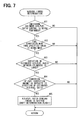
- FIG. 5 is a flow chart to show a flow of a processing of a performance condition determination routine of the first embodiment
- FIG. 6 is a flow chart to show a flow of a processing of an individual cylinder air-fuel ratio control routine
- FIG. 7 is a flow chart to show a flow of a processing of an air-fuel ratio sensing timing determination routine
- FIG. 8 is a flow chart to show a flow of a processing of an air-fuel ratio sensing timing shift learning correction routine
- FIG. 9 is a flow chart to show a flow of a processing of a Local learning performance routine
- FIG. 10 is a flow chart to show a flow of a processing of a Local learning index calculation routine
- FIG. 11 is a flow chart to show a flow of a processing of a Global learning performance routine
- FIG. 12 is a flow chart to show a flow of a processing of a Global learning index calculation routine
- FIG. 13 is a table to show a cylinder assumed in a case where an air-fuel ratio sensing timing is assumed to be changed;
- FIG. 14 is a flow chart to show a flow of a processing of a rapid acceleration and deceleration determination routine
- FIG. 15 is a flow chart to show a flow of a processing of a performance condition determination routine of a second embodiment
- FIG. 16 is a time chart to show an example of performing a control of the second embodiment
- FIG. 17 is a time chart to show an example of performing a control of the second embodiment
- FIG. 18 is a flow chart to show a flow of a processing of an individual cylinder air-fuel ratio control routine
- FIG. 19 is a flow chart to show a flow of a processing of an air-fuel ratio sensing timing setting routine
- FIG. 20 is a chart to conceptually show an example of a map of a base air-fuel ratio sensing timing Sb;
- FIG. 21 is a chart to conceptually show an example of a map of a correction amount S 1 according to an ignition timing
- FIG. 22 is a chart to conceptually show an example of a map of a correction amount S 2 according to a fuel injection timing
- FIG. 23 is a chart to conceptually show an example of a map of a correction amount S 3 according to a load change amount
- FIG. 24 is a time chart to show an example of making an air-fuel ratio sensing timing correction according to an ignition timing
- FIG. 25 is a time chart to show an example of making an air-fuel ratio sensing timing correction according to a fuel injection timing
- FIG. 26 is a block diagram to illustrate an air-fuel ratio control function
- FIG. 27 is a flow chart to show a flow of a processing of a main F/B control routine
- FIG. 28 is a flow chart to show a flow of a processing of an individual cylinder air-fuel ratio estimation routine
- FIG. 29 is a flow chart to show a flow of a processing of an individual cylinder air-fuel ratio control and convergence determination routine
- FIG. 30 is a flow chart to show a flow of the processing of the individual cylinder air-fuel ratio control and convergence determination routine
- FIG. 31 is a flow chart to show a flow of a processing of an imbalance failure possibility determination routine of a fourth embodiment
- FIG. 32 is a time chart to show an example of performing a control of the fourth embodiment
- FIG. 33 is a time chart to show an effect of the fourth embodiment
- FIG. 34 is a flow chart to show a flow of a processing of an imbalance failure possibility determination routine of an embodiment 5;
- FIG. 35 is a flow chart to show a flow of a processing of an imbalance failure possibility determination routine of a sixth embodiment.
- a first embodiment of the present disclosure will be described on the basis of FIG. 1 to FIG. 13 .
- an in-line 4-cylinder engine 11 of an internal combustion engine has four cylinders of a first cylinder #1 to a fourth cylinder #4.
- the engine 11 has an air cleaner 13 provided on the most upstream portion of an intake pipe 12 thereof and has an air flow meter 14 provided on a downstream side of the air cleaner 13 , the air flow meter 14 detecting an intake air amount.
- On the downstream side of the air flow meter 14 are provided a throttle valve 15 , whose opening is regulated by a motor or the like, and a throttle opening sensor 16 for sensing an opening (throttle opening) of the throttle valve 15 .
- a surge tank 17 on the downstream side of the throttle valve 15 is provided a surge tank 17 , and the surge tank 17 is provided with an intake pipe pressure sensor 18 for sensing an intake pipe pressure. Still further, the surge tank 17 is provided with intake manifolds 19 each of which introduces air into the individual cylinder of the engine 11 and the intake manifold 19 of the individual cylinder has a fuel injection valve 20 fixed at an intake port thereof, the fuel injection valve 20 injecting fuel to the intake port. While the engine 11 is operated, the fuel in a fuel tank 21 is sent to a delivery pipe 23 by a fuel pump 22 and is injected from the fuel injection valve 20 of the individual cylinder at an injection timing of the individual cylinder. The delivery pipe 23 is provided with a fuel pressure sensor 24 for sensing a fuel pressure.
- the engine 11 is provided with variable valve timing mechanisms 27 , 28 which vary a valve timing (opening/closing timing) of an intake valve 25 and a valve timing (opening/closing timing) of an exhaust valve 26 , respectively.
- the engine 11 is provided with an intake cam angle sensor 31 for outputting a cam angle signal in synchronization with the rotation of an intake cam shaft 29 and an exhaust cam angle sensor 32 for outputting a cam angle signal in synchronization with the rotation of an exhaust cam shaft 30 .
- the engine 11 is provided with a crank angle sensor 33 for outputting a pulse of a crank angle signal at intervals of a specified crank angle (for example, 30 CA) in synchronization with the rotation of a crankshaft of the engine 11 .
- an exhaust gas collection part 34 a through which exhaust gases of the individual cylinders flow together, of an exhaust pipe 34 of the engine 11 (a part at which the exhaust manifolds 35 of the individual cylinders meet or on the downstream side of the part) is provided an air-fuel ratio sensor 36 for sensing an air-fuel ratio of the exhaust gas.
- a catalyst 37 On the downstream side of the air-fuel ratio sensor 36 is provided a catalyst 37 , for example, a three-way catalyst for cleaning CO, HC, and NOx in the exhaust gas.
- a cylinder block of the engine 11 is provided with a cooling water temperature sensor 38 for sensing a cooling water temperature.
- the outputs of these various kinds of sensors are inputted to an electronic control unit (ECU) 39 .
- the ECU 39 is mainly constructed of a microcomputer and executes various kinds of programs, which are stored in a built-in ROM (storage medium) and control the engine 11 , thereby controlling a fuel injection amount, an ignition timing, and a throttle opening (an intake air amount) according to an engine operation state.
- the ECU 39 performs an air-fuel ratio F/B control for feeding back an air-fuel ratio of an air-fuel mixture (for example, a fuel injection amount) on the basis of an output of the air-fuel ratio sensor 36 in such a way that an air-fuel ratio of the exhaust gas matches a target air-fuel ratio.
- an air-fuel ratio F/B control for feeding back an air-fuel ratio of an air-fuel mixture (for example, a fuel injection amount) on the basis of an output of the air-fuel ratio sensor 36 in such a way that an air-fuel ratio of the exhaust gas matches a target air-fuel ratio.
- an air-fuel ratio deviation calculation part 40 calculates a deviation between a sensed air-fuel ratio (an air-fuel ratio of the exhaust gas sensed by the air-fuel ratio sensor 36 ) and a target air-fuel ratio
- an air-fuel ratio F/B control part 41 calculates an air-fuel ratio correction factor in such a way that the deviation between the sensed air-fuel ratio and the target air-fuel ratio becomes small.
- an injection amount calculation part 42 calculates a fuel injection amount on the basis of a base injection amount, which is calculated on the basis of an engine rotation speed and an engine load (intake pipe negative pressure and intake air amount), and the calculated air-fuel ratio correction factor and controls the fuel injection valve 20 of the individual cylinder on the basis of the calculated fuel injection amount.
- the ECU 39 performs an individual cylinder air-fuel ratio control routine shown in FIG. 6 , which will be described later.
- the ECU 39 performs an individual cylinder air-fuel ratio estimation for estimating an air-fuel ratio of an individual cylinder for each cylinder on the basis of a sensed value of the air-fuel ratio sensor 36 , which is sensed at each air-fuel ratio sensing timing of the individual cylinder, thereby estimating an estimated air-fuel ratio of the individual cylinder.
- the ECU 39 performs an individual cylinder air-fuel ratio control for controlling an air-fuel ratio of the individual cylinder for each cylinder on the basis of the estimated air-fuel ratio of the individual cylinder.
- an individual cylinder air-fuel ratio estimation part 43 estimates an air-fuel ratio of an individual cylinder for each cylinder on the basis of the sensed value of the air-fuel ratio sensor 36 (actual air-fuel ratio of the exhaust gas flowing through the exhaust gas collection part 34 a ) by the use of an individual cylinder air-fuel ratio estimation model, which will be described later, and a base air-fuel ratio calculation part 44 calculates a mean value of the estimated air-fuel ratios of all cylinders and sets the mean value for a base air-fuel ratio.
- an individual cylinder air-fuel ratio deviation calculation part 45 calculates a deviation between the estimated air-fuel ratio of the individual cylinder and the base air-fuel ratio for each cylinder
- an individual cylinder air-fuel ratio control part 46 calculates, for example, a fuel correction amount (a correction amount of the fuel injection amount) as an individual cylinder correction value for each cylinder in such a way that a deviation between the estimated air-fuel ratio of the individual cylinder and the base air-fuel ratio becomes small.
- an individual cylinder air-fuel ratio estimation model for estimating an air-fuel ratio of an individual cylinder (hereinafter referred to as “an individual cylinder air-fuel ratio estimation model”) on the basis of the sensed value (an actual air-fuel ratio of the exhaust gas flowing through the exhaust gas collection part 34 a ) of the air-fuel ratio sensor 36 .
- the sensed value of the air-fuel ratio sensor 36 is expressed by a model that is the sum of a value, which is obtained by multiplying a history of the estimated air-fuel ratio of the individual cylinder in the exhaust gas collection part 34 a by a specified weight, and a value, which is obtained by multiplying a history of the sensed value of the air-fuel ratio sensor 36 by another specified weight, and the air-fuel ratio of the individual cylinder is estimated by the use of the model.
- a Kalman filter is used as an observer.
- a model of the gas exchange in the exhaust gas collection part 34 a is approximated by the following equation (1).
- ys ( t ) k 1 ⁇ u ( t ⁇ 1)+ k 2 ⁇ u ( t ⁇ 2) ⁇ k 3 ⁇ ys ( t ⁇ 1) ⁇ k 4 ⁇ ys ( t ⁇ 2) (1)
- ys is a sensed value of the air-fuel ratio sensor 36
- u is an air-fuel ratio of gas flowing into the exhaust gas collection part 34 a
- “k1” to “k4” are constants.
- An exhaust gas system has a first order delay element of a gas inflow and a gas mixture in the exhaust gas collection part 34 a and a first order delay element by a response delay of the air-fuel ratio sensor 36 . Then, in the equation (1) described above, the histories of last two times are referred to in consideration of these first order delay elements.
- Equation (1) When the equation (1) is transformed into a state space model, the following equations (2a) and (2b) can be derived.
- X ( t+ 1) A ⁇ X ( t )+ B ⁇ u ( t )+ W ( t ) (2a)
- Y ( t ) C ⁇ X ( t )+ D ⁇ u ( t ) (2b)
- A”, “B”, “C”, and “D” are parameters of the model
- Y is a sensed value of the air-fuel ratio sensor 36
- X is an estimated air-fuel ratio of an individual cylinder as a state variable
- W is noise.
- Equation (3) X ⁇ ( k+ 1
- k ) A ⁇ X ⁇ ( k
- X ⁇ is an estimated air-fuel ratio of an individual cylinder and K is a Kalman gain.
- k) means that an estimated value at the next time (k+1) is found from an estimated value at a time (k).
- the air-fuel ratio of the individual cylinder can be estimated in sequence along with the progression of a combustion cycle.
- an air-fuel ratio sensing timing sampling timing of the output of the air-fuel ratio sensor 36 .
- a time lag from the time when the exhaust gas exhausted from the individual cylinder reaches near the air-fuel ratio sensor 36 to the time when the air-fuel ratio of the exhaust gas is sensed by the air-fuel ratio (hereinafter referred to as “a response delay of an exhaust system”) will be varied according to an engine operation state.
- the air-fuel ratio sensing timing of the individual cylinder is set by a map according to the engine operation state (for example, an engine load, an engine rotation speed, and the like) and the output of the air-fuel ratio sensor 36 is taken in the ECU 39 .
- the air-fuel ratio sensing timing of the individual cylinder is set in such a way that as the engine load is smaller, the air-fuel ratio sensing timing of the individual cylinder is shifted to a delay side.
- the length of the exhaust manifold 35 from an exhaust port of an individual cylinder to the air-fuel ratio sensor 36 is different for each cylinder and the flow of the exhaust gas of the individual cylinder is complicatedly varied according to the engine operation state (the engine rotation speed, an air amount filled in the cylinder, and the like).
- the response delay of the exhaust system is varied also by a variation in the manufacture of the engine 11 and by a secular change, so it is difficult to map a relationship between the response delay of the exhaust system of the individual cylinder (the air-fuel ratio sensing timing of the individual cylinder) and the engine load with high accuracy in the process of designing and manufacturing the engine 11 . For this reason, there is a possibility that the air-fuel ratio sensing timing of the individual cylinder will be shifted from a proper air-fuel ratio sensing timing.
- the ECU 39 performs the respective routines shown in FIG. 7 to FIG. 12 , which will be described later. That is, while the ECU 39 performs the individual cylinder air-fuel ratio control, the ECU 39 makes an air-fuel ratio sensing timing determination for determining whether or not the air-fuel ratio sensing timing is shifted from the proper air-fuel ratio sensing timing on the basis of the estimated air-fuel ratio. When the ECU 39 determines that the air-fuel ratio sensing timing is shifted from the proper air-fuel ratio sensing timing, the ECU 39 makes an air-fuel ratio sensing timing correction for correcting an air-fuel ratio sensing timing.
- the ECU 39 performs a Local learning for correcting the air-fuel ratio sensing timing in such a way that a variation in the sensed value of the air-fuel ratio sensor 36 becomes maximum within one cycle (720 CA) of the engine 11 .
- the ECU 39 performs the Local learning
- the ECU 39 performs the individual cylinder air-fuel ratio control
- the ECU 39 performs a Global learning for correcting the air-fuel ratio sensing timing on the basis of a relationship between a change in the estimated air-fuel ratio of at least one cylinder and a change in an individual cylinder correction value (for example, a fuel correction amount) of the cylinder.
- the ECU 39 calculates a correlation value between a change in the estimated air-fuel ratio of at least one cylinder and a change in the individual cylinder correction value of a cylinder number after the estimated air-fuel ratio being changed and corrects the air-fuel ratio sensing timing in such a way that the correlation value becomes maximum.
- a correct air-fuel ratio sensing timing of a certain cylinder is not necessarily near a present air-fuel ratio sensing timing of the cylinder, but it can be also considered that, for example, the correct air-fuel ratio sensing timing of the certain cylinder is delayed to the present air-fuel ratio sensing timing of the next combustion cylinder or to a delay side thereof or that the correct air-fuel ratio sensing timing of the certain cylinder is advanced to the present air-fuel ratio sensing timing of the last combustion cylinder or to an advance side thereof. For example, as shown in FIG.
- a timing when an actual air-fuel ratio of the first cylinder #1 is sensed most accurately is not the present air-fuel ratio sensing timing of the first cylinder #1 but is the present air-fuel ratio sensing timing of the third cylinder #3.
- an individual cylinder air-fuel ratio control is performed by the use of an individual cylinder correction value (for example, a fuel correction amount) of the first cylinder #1, which is calculated on the basis of an estimated air-fuel ratio of the first cylinder #1, which is estimated on the basis of the present air-fuel ratio sensing timing of the first cylinder #1
- an actual air-fuel ratio of the first cylinder #1 is changed in response to a change in the individual cylinder correction value of the first cylinder #1.
- the estimated air-fuel ratio of the first cylinder #1 is not changed in response to the change in the individual cylinder correction value of the first cylinder #1, but an estimated air-fuel ratio of the third cylinder #3 results in being changed in response to the change in the individual cylinder correction value of the first cylinder #1.
- the ECU 39 corrects the air-fuel ratio sensing timing on the basis of the relationship between the change in the estimated air-fuel ratio of at least one cylinder and the change in the individual cylinder correction value (for example, the fuel correction amount) of the cylinder while performing the individual cylinder air-fuel control. Hence, the ECU 39 can correct a shift of the air-fuel ratio sensing timing from the proper air-fuel ratio sensing timing.
- the ECU 39 calculates the correlation value between the change in the estimated air-fuel ratio of at least one cylinder and the change in the individual cylinder correction value of the cylinder number after the estimated air-fuel ratio being changed and corrects the air-fuel ratio sensing timing on the basis of the correlation value.
- a timing when an actual air-fuel ratio of the first cylinder #1 is sensed most accurately is not the present air-fuel ratio sensing timing of the first cylinder #1 but is the middle of the present air-fuel ratio sensing timings of the second cylinder #2 and the fourth cylinder #4.
- the air-fuel ratio sensing timing is corrected by the Local learning in such a way that a variation in the sensed value of the air-fuel ratio sensor 36 becomes maximum within one cycle (720 CA) of the engine 11 .
- the air-fuel ratio is varied within one cycle but a maximum variation in the air-fuel ratio can be sensed and any one of the sensed value of the air-fuel ratio sensor 36 at the air-fuel ratio sensing timing of the individual cylinder can be a sensed value of high accuracy of any one of an actual air-fuel ratio of the individual cylinder.
- any one of an estimated air-fuel ratio of the individual cylinder can be a sensed value of any one of an actual air-fuel ratio of the individual cylinder.
- the Global learning it is possible to correct a shift of the air-fuel ratio sensing timing from the proper air-fuel ratio sensing timing with high accuracy.
- the ECU 39 performs the respective routines shown in FIG. 4 and FIG. 5 , which will be described later. That is, the ECU 39 determines whether or not a misfire is caused in the engine 11 . When the ECU 39 determines that the misfire is caused in the engine 11 , the ECU 39 stops the individual cylinder air-fuel ratio estimation and the individual cylinder air-fuel ratio control and resets the individual cylinder correction value by the individual cylinder air-fuel ratio control.
- a misfire determination routine shown in FIG. 4 is invoked at intervals of a specified crank angle (for example, 30 CA) in synchronization with an output pulse of a crank angle sensor 33 and functions as a misfire determination part.
- a specified crank angle for example, 30 CA
- a 30 CA time T 30 that is a time required for a crankshaft of the engine 11 to rotate 30 CA is calculated on the basis of an output signal of the crank angle sensor 33 at intervals of a specified timing (for example, at intervals of a specified misfire determination crank angle).
- step 102 a time change amount DMF (information of a variation in the rotation of an engine) that is a difference between a 30 CA time T 30 ( i ) of this time and a 30 CA time T 30 (i ⁇ 1) of the last time is calculated.
- DMF information of a variation in the rotation of an engine
- step 103 it is determined whether or not the time change amount DMF is more than a misfire determination value.
- step 103 In a case where it is determined in this step 103 that the time change amount DMF is not more than the misfire determination value, the routine proceeds to step 104 where it is determined that a misfire is not caused in the engine 11 and where a misfire flag is reset to “0”. Then, the present routine is finished.
- step 103 determines that the time change amount DMF is more than the misfire determination value.
- step 105 it is determined that a misfire is caused in the engine 11 and where the misfire flag is set to “1”. Then, the present routine is finished.
- a misfired is caused in the engine 11 by comparing the time change amount DMF with the misfire determination value.
- a method for determining whether or not a misfire is caused in the engine 11 is not limited to this but may be modified as appropriate. For example, it is also recommended to determine whether or not a misfire is caused in the engine 11 by comparing an amount of change in the rotation of the engine with a misfire determination value.
- a performance condition determination routine shown in FIG. 5 is invoked at intervals of a specified crank angle (for example, 30 CA) in synchronization with the output pulse of the crank angle sensor 33 .
- a specified crank angle for example, 30 CA
- step 201 determines whether or not the air-fuel ratio sensor 36 can be used (for example, the air-fuel ratio sensor 36 is normal and in an active state).
- step 202 the routine proceeds to step 203 where it is determined whether or not an engine operation state (for example, an engine load and an engine rotation speed) is within a specified range (for example, a range in which an air-fuel ratio estimation accuracy can be secured).
- an engine operation state for example, an engine load and an engine rotation speed
- a specified range for example, a range in which an air-fuel ratio estimation accuracy can be secured.
- step 204 it is determined that a performance condition of the individual cylinder air-fuel ratio control holds and where a performance condition flag is set to “1”, and then the present routine is finished.
- the routine proceeds to step 205 where an individual cylinder correction value (a fuel correction amount) of the individual cylinder is reset to a specified value (for example, an initial value or a value before a timing when it is determined that the misfire is caused). Then, the routine proceeds to step 206 where it is determined that the performance condition of the individual cylinder air-fuel ratio control does not hold and where the performance condition flag is reset to “0”. Then, the present routine is finished.
- a specified value for example, an initial value or a value before a timing when it is determined that the misfire is caused.
- the routine shown in FIG. 5 functions as a stop part.
- step 202 or 203 the routine proceeds to step 206 where it is determined that the performance condition of the individual cylinder air-fuel ratio control does not hold and the performance condition flag is reset to “0”. Then, the present routine is finished.
- An individual cylinder air-fuel ratio control routine shown in FIG. 6 is invoked at intervals of a specified crank angle (for example, 30 CA) in synchronization with the output pulse of the crank angle sensor 33 and functions as an individual cylinder air-fuel ratio control part.
- a specified crank angle for example, 30 CA
- step 301 whether or not the performance condition of the individual cylinder air-fuel ratio control holds is determined by whether or not the performance condition flag is set to “1”.
- an air-fuel ratio sensing timing of the individual cylinder (sampling timing of the output of the air-fuel ratio sensor 36 ) is set by a map according to an engine load at that time (for example, intake pipe pressure).
- the air-fuel ratio sensing timing of the individual cylinder may be set by a map according to the engine load and the engine rotation speed.
- the map used for setting the air-fuel ratio sensing timing is learned and corrected by a Local learning performance routine shown in FIG. 9 , which will be describe later, and by a Global learning performance routine shown in FIG. 11 , which will be describe later.
- step 303 it is determined whether or not a present crank angle is an air-fuel ratio sensing timing set in the step 302 . If it is determined that the present crank angle is the air-fuel ratio sensing timing set in the step 302 , the present routine is finished without performing pieces of processing in the following steps.
- step 302 the routine proceeds to step 304 where the output of the air-fuel ratio sensor 36 (sensed value of the air-fuel ratio) is read.
- step 305 an air-fuel ratio of a cylinder, whose air-fuel ratio is to be estimated this time, is estimated on the basis of the sensed value of the air-fuel ratio sensor 36 by the use of the individual cylinder air-fuel ratio estimation model described above.
- the processing of this step 305 functions as an individual cylinder air-fuel ratio estimation part.
- step 306 a mean value of the estimated air-fuel ratios of all cylinders is calculated and where the mean value is set for a base air-fuel ratio (target air-fuel ratio of all cylinders).
- step S 307 a deviation between the estimated air-fuel ratio of the individual cylinder and the base air-fuel ratio is calculated and where a fuel correction amount is calculated as an individual cylinder correction value of the individual cylinder in such a way that the deviation is reduced.
- step 308 the fuel injection amount of the individual cylinder is corrected on the basis of the fuel correction amount of the individual cylinder to thereby correct the air-fuel ratio of an air-fuel mixture to be supplied to the individual cylinder, thereby controlling the air-fuel ratio in such a way that a variation in the air-fuel ratio between the cylinders is reduced.
- An air-fuel ratio sensing timing determination routine shown in FIG. 7 is invoked at intervals of a specified crank angle (for example, 30 CA) in synchronization with the output pulse of the crank angle sensor 33 .
- a specified crank angle for example, 30 CA
- the present routine is invoked, first, in step 401 , it is determined whether or not an individual cylinder air-fuel ratio control is being performed. If it is determined that the individual cylinder air-fuel ratio control is not being performed, the present routine is finished without performing pieces of processing in the following steps.
- step 402 it is determined, for example, by any one or two or more of the following conditions (A1) to (A3) whether or not a fuel correction not less than a specified value is being made.
- Whether or not a fuel correction not less than a specified value is being made is determined by whether or not a deviation between a maximum fuel correction amount and a minimum fuel correction amount of the fuel correction amounts of the individual cylinders is not less than a specified value.
- (A3) Whether or not a fuel correction not less than a specified value is being made is determined by whether or not the time that elapses after a fuel correction is started is not less than a specified time.
- step 402 If it is determined in this step 402 that a fuel correction not less than a specified value is not being made, the present routine is finished without performing any more processing.
- step 402 determines whether or not the degree of a variation in the estimated air-fuel ratio between the cylinders is large.
- step 403 If it is determined in this step 403 that the degree of a variation in the estimated air fuel ratio between the cylinders is small, it is determined that an air-fuel ratio sensing timing is correct and the present routine is finished without performing any more processing.
- step 403 determines whether or not the degree of a variation in the estimated air fuel ratio between the cylinders is large. If it is determined in the step 403 that the degree of a variation in the estimated air fuel ratio between the cylinders is large, it is determined that an air-fuel ratio sensing timing can be shifted from a proper air-fuel ratio sensing timing and the routine proceeds to step 404 . Whether or not a direction in which a fuel correction amount of the individual cylinder is increased or decreased is opposite to a direction in which an estimated air-fuel ratio is increased or decreased is determined in step 404 , for example, by whether or not a deviation between a rate of change in a fuel correction amount of the individual cylinder and a rate of change in an estimated air-fuel ratio of the individual cylinder is not less than a specified value.
- step 404 If it is determined in this step 404 that a direction in which a fuel correction amount of the individual cylinder is increased or decreased is same as a direction in which an estimated air-fuel ratio is increased or decreased, it is determined that an air-fuel ratio sensing timing is correct and the present routine is finished without performing any other processing.
- step 404 determines whether a direction in which a fuel correction amount of the individual cylinder is increased or decreased is opposite to a direction in which an estimated air-fuel ratio is increased or decreased. If it is determined in the step 404 that a direction in which a fuel correction amount of the individual cylinder is increased or decreased is opposite to a direction in which an estimated air-fuel ratio is increased or decreased, the routine proceeds to step 405 where it is determined that an air-fuel ratio sensing timing is shifted from a proper air-fuel ratio sensing timing and where a shift determination flag is set to “1” and then the present routine is finished.
- An air-fuel ratio sensing timing shift learning correction routine shown in FIG. 8 is invoked at intervals of a specified crank angle (for example, 30 CA) in synchronization with the output pulse of the crank angle sensor 33 .
- a specified crank angle for example, 30 CA
- the present routine is invoked, first, in step 501 , it is determined whether or not a Local learning completion flag is set to “1”. If it is determined that a Local learning completion flag is set to “1”, the routine proceeds to step 502 where a counter after Local learning completion is counted up.
- step 503 whether or not an air-fuel ratio sensing timing is shifted from a proper air-fuel ratio sensing timing is determined, by the use of the air-fuel ratio sensing timing determination routine shown in FIG. 7 , by whether or not a shift determination flag is set to “1”.
- the routine proceeds to step 504 where it is determined whether or not a Local learning completion flag is “0” or whether or not a counted value of a counter after Local learning completion is not less than a specified value T 1 .
- step 504 determines that the Local learning completion flag is “0” or that the counted value of the counter after Local learning completion is not less than the specified value T 1 .
- the routine proceeds to step 505 .
- the counted value of the counter after Local learning completion is reset to “0” and the Local learning completion flag is reset to “0” and a Local learning performance counter is counted up.
- step 506 an individual cylinder correction value (fuel correction amount) of the individual cylinder is held at the last value.
- step 507 a Local learning performance routine shown in FIG. 9 , which will be described later, is performed, whereby a Local learning for correcting an air-fuel ratio sensing timing is performed in such a way that a variation in the sensed value of the air-fuel ratio sensor 36 becomes maximum within one cycle.
- the routine proceeds to step 508 where it is determined whether or not the counted value of the counter after Local learning completion is not less than a specified value T 2 .
- the specified value T 2 is a value smaller than the specified value T 1 (T 2 ⁇ T 1 ).
- step 508 determines that the counted value of the counter after Local learning completion is not less than the specified value T 2 . It is determined that a sufficient time necessary for the individual cylinder air-fuel ratio control to be stable elapses after the Local learning is completed. Then, the routine proceeds to step 509 where a Global learning performance counter is counted up.
- step 510 a Global learning performance routine shown in FIG. 11 , which will be described later, is performed, thereby performing a Global learning for correcting an air-fuel sensing timing on the basis of a relationship between a change in the estimated air-fuel ratio of the individual cylinder and a change in the individual cylinder correction value (fuel correction value) of the individual cylinder.
- a Local learning performance routine shown in FIG. 9 is a subroutine performed in step 507 of the air-fuel ratio sensing timing shift learning correction routine shown in FIG. 8 .
- a Local learning for correcting an air-fuel ratio sensing timing in such a way that a variation in the sensed value of the air-fuel ratio sensor 36 becomes maximum within one cycle.
- an air-fuel ratio sensing timing is corrected in such a way that a value corresponding to the variance of the sensed value of the air-fuel ratio sensor 36 , which is sensed at intervals of an air-fuel ratio sensing timing of the individual cylinder, becomes maximum.
- step 601 it is determined whether or not the counted value of the Local learning performance counter is not more than a specified value (for example, a value corresponding to 30 cycles).
- step 601 If it is determined in this step 601 that the counted value of the Local learning performance counter is not more than the specified value, the routine proceeds to step 602 where a Local learning index calculation routine shown in FIG. 10 is performed to thereby calculate a Local learning index in the following manner.
- a value hereinafter referred to as “the variance of the sensed air-fuel ratio” corresponding to the variance of the sensed value of the air-fuel ratio sensor 36 , which is sensed at intervals of the air-fuel ratio sensing timing of the individual cylinder, is calculated and the variance of the sensed air-fuel ratio is assumed to be a Local learning index.
- Variance V (Dcal ⁇ 90) of an sensed air-fuel ratio in a case where an air-fuel ratio sensing timing of the first cylinder #1 is assumed to be a first timing L 1 Dcal ⁇ 90 (timing advanced by 90 CA from a present air-fuel ratio sensing timing Dcal of the first cylinder #1) is calculated by the following equation.
- N is the number of cylinders per one air-fuel ratio sensor 36 (for example, 4)
- ⁇ (k) is a sensed value of the air-fuel ratio sensor 36 at k [CA].
- Mean ⁇ (k) is a mean value of ⁇ (k), ⁇ (k+720/N*1), ⁇ (k+720/N*2), ⁇ (k+720/N*3) ⁇ .
- ⁇ (k) is calculated as an equivalent ratio (a reciprocal of an excess air-fuel ratio).
- V (Dcal ⁇ 60) of a sensed air-fuel ratio in a case where an air-fuel ratio sensing timing of the first cylinder #1 is assumed to be a second timing L 2 Dcal ⁇ 60 (timing advanced by 60 CA from the present air-fuel ratio sensing timing Dcal of the first cylinder #1) is calculated by the following equation.
- Variance V (Dcal ⁇ 30) of a sensed air-fuel ratio in a case where an air-fuel ratio sensing timing of the first cylinder #1 is assumed to be a third timing L 3 Dcal ⁇ 30 (timing advanced by 30 CA from the present air-fuel ratio sensing timing Dcal of the first cylinder #1) is calculated by the following equation.
- Variance V (Dcal+30) of a sensed air-fuel ratio in a case where an air-fuel ratio sensing timing of the first cylinder #1 is assumed to be a fifth timing L 5 Dcal+30 (timing delayed by 30 CA from the present air-fuel ratio sensing timing Dcal of the first cylinder #1) is calculated by the following equation.
- V (Dcal+60) of a sensed air-fuel ratio in a case where an air-fuel ratio sensing timing of the first cylinder #1 is assumed to be a sixth timing L 6 Dcal+60 (timing delayed by 60 CA from the present air-fuel ratio sensing timing Dcal of the first cylinder #1) is calculated by the following equation.
- the routine proceeds to step 603 shown in FIG. 9 .
- the variance V of the respective sensed air-fuel ratios is normalized.
- step 604 in a case where the air-fuel ratio sensing timing of the first cylinder #1 is assumed to be the respective timings L 1 to L 6 , a normalized index of this time is integrated to a normalized index of the last time (data obtained by normalizing the variance V of the sensed air-fuel ratio) to thereby update an integrated value of the normalized index.
- step 601 determines that a counted value of the Local learning performance counter becomes more than a specified value. If it is determined that an integrated value in a specified period of the normalized index is calculated. Then, the routine proceeds to step 605 where, of the respective timings L 1 to L 6 , a timing when the integrated value in a specified period of the normalized index becomes maximum is selected as an optimal timing.
- step 606 the selected optimal timing (the timing when the integrated value in a specified period of the normalized index becomes maximum) is learned as an air-fuel ratio sensing timing of the first cylinder #1 and air-fuel ratio sensing timings of the other cylinders (the second cylinder #2 to the fourth cylinder #4) are learned with the air-fuel ratio sensing timing of the first cylinder #1 as a standard.
- These learned values are updated and stored in a learned value storage region of a rewritable nonvolatile memory such as a backup RAM or the like of the ECU 39 .
- step 607 the routine proceeds to step 607 where the counted value of the Local learning performance counter is reset to “0” and where the shift determination flag is reset to “0” and where the Local learning completion flag is set to “1”. Then, the routine proceeds to step 608 where individual cylinder correction value (fuel correction amount) of the individual cylinder is reset to a specified value (for example, an initial value or a value before a shift determination). Then, the present routine is finished.
- a specified value for example, an initial value or a value before a shift determination
- a Global learning performance routine shown in FIG. 11 is a subroutine performed in step 510 of the air-fuel ratio sensing timing shift learning correction routine shown in FIG. 8 .
- the Global learning for correcting an air-fuel ratio sensing timing on the basis of a relationship between a change in the estimated air-fuel ratio of the individual cylinder and a change in the individual cylinder correction value (fuel correction value) of the individual cylinder.
- the Global learning in respective cases where an individual cylinder number assumed by the estimated air-fuel ratio of the individual cylinder is changed hypothetically in a plurality of ways, a correlation value between a change in the estimated air-fuel ratio of the individual cylinder and a change in an individual cylinder correction value (fuel correction value) of a cylinder number after the estimated air-fuel ratio being changed is calculated and an air-fuel ratio sensing timing is corrected in such a way that the correlation value becomes maximum.
- step 701 it is determined whether or not this timing is a Global learning index calculation timing (for example, at intervals of 720 CA). If it is determined that this timing is not the Global learning index calculation timing, the present routine is finished without performing the pieces of processing in step 702 and subsequent steps.
- a Global learning index calculation timing for example, at intervals of 720 CA.
- step 701 determines whether this timing is the Global learning index calculation timing. If it is determined in the step 701 that this timing is the Global learning index calculation timing, the routine proceeds to step 702 where the counted value of the Global learning performance counter is not more than a specified value (for example, a value corresponding to 30 cycles).
- a specified value for example, a value corresponding to 30 cycles.
- step 702 If it is determined in this step 702 that the counted value of the Global learning performance counter is not more than the specified value, the routine proceeds to step 703 where a Global learning index calculation routine shown in FIG. 12 is performed to thereby calculate a Global learning index in the following manner.
- a Global learning index calculation routine shown in FIG. 12 is performed to thereby calculate a Global learning index in the following manner.
- an air-fuel ratio sensing timing of the first cylinder #1 is assumed to be respective timings G 1 to G 4 [CA]
- a correlation value between a change in the estimated air-fuel ratio of the individual cylinder and a change in the fuel correction amount of the individual cylinder is calculated and the correlation value is made a Global learning index.
- ⁇ #i (t) is a calculated value of this time of the estimated air-fuel ratio of an i-th cylinder #i and ⁇ #i (t ⁇ n) is a calculated value of n times ago of the estimated air-fuel ratio of the i-th cylinder #i.
- Cmp #i (t) is a calculated value of this time of the fuel correction amount of the i-th cylinder #i and Cmp #i (t ⁇ n) is a calculated value of n times ago of the fuel correction amount of the i-th cylinder #i.
- n is a specified integer not less than 1.
- step 712 in cases where the air-fuel ratio sensing timing of the first cylinder #1 is assumed to be the following respective timings G 1 to G 4 (CA), a correlation value between a change in the estimated air-fuel ratio of the individual cylinder and a change in the fuel correction amount of the individual cylinder (the sum of the product of a change amount ⁇ of the estimated air-fuel ratio and a change amount ⁇ Cmp of the fuel correction amount) is calculated respectively.
- an estimated air-fuel ratio ⁇ #3 of the third cylinder #3 at the present air-fuel ratio sensing timing is calculated as an estimated air-fuel ratio of the third cylinder #3
- an estimated air-fuel ratio ⁇ #4 of the fourth cylinder #4 at the present air-fuel ratio sensing timing is calculated as an estimated air-fuel ratio of the fourth cylinder #4
- an estimated air-fuel ratio ⁇ #2 of the second cylinder #2 at the present air-fuel ratio sensing timing is calculated as an estimated air-fuel ratio of the second cylinder #2.
- Cor ( Dcal ) ⁇ #1( t ) ⁇ Cmp# 1( t )+ ⁇ #3( t ) ⁇ Cmp# 3( t )+ ⁇ #4( t ) ⁇ Cmp# 4( t )+ ⁇ #2( t ) ⁇ Cmp# 2( t ) (12)
- an estimated air-fuel ratio ⁇ #3 of the third cylinder #3 at the present air-fuel ratio sensing timing is calculated as an estimated air-fuel ratio of the first cylinder #1
- an estimated air-fuel ratio ⁇ #4 of the fourth cylinder #4 at the present air-fuel ratio sensing timing is calculated as an estimated air-fuel ratio of the third cylinder #3
- an estimated air-fuel ratio ⁇ #2 of the second cylinder #2 at the present air-fuel ratio sensing timing is calculated as an estimated air-fuel ratio of the fourth cylinder #4.
- Cor ( Dcal+ 180) ⁇ #3( t ) ⁇ Cmp# 1( t )+ ⁇ #4( t ) ⁇ Cmp# 3( t )+ ⁇ #2( t ) ⁇ Cmp# 4( t )+ ⁇ #1( t ) ⁇ Cmp# 2( t ) (13)
- an estimated air-fuel ratio ⁇ #3 of the third cylinder #3 at the present air-fuel ratio sensing timing is calculated as an estimated air-fuel ratio of the second cylinder #2
- an estimated air-fuel ratio ⁇ #4 of the fourth cylinder #4 at the present air-fuel ratio sensing timing is calculated as an estimated air-fuel ratio of the first cylinder #1
- an estimated air-fuel ratio ⁇ #2 of the second cylinder #2 at the present air-fuel ratio sensing timing is calculated as an estimated air-fuel ratio of the third cylinder #3.
- Cor ( Dcal+ 360) ⁇ #4( t ) ⁇ Cmp# 1( t )+ ⁇ #2( t ) ⁇ Cmp# 3( t )+ ⁇ #1( t ) ⁇ Cmp# 4( t )+ ⁇ #3( t ) ⁇ Cmp# 2( t ) (14)
- an estimated air-fuel ratio ⁇ #3 of the third cylinder #3 at the present air-fuel ratio sensing timing is calculated as an estimated air-fuel ratio of the fourth cylinder #4
- an estimated air-fuel ratio ⁇ #4 of the fourth cylinder #4 at the present air-fuel ratio sensing timing is calculated as an estimated air-fuel ratio of the second cylinder #2
- an estimated air-fuel ratio ⁇ #2 of the second cylinder #2 at the present air-fuel ratio sensing timing is calculated as an estimated air-fuel ratio of the first cylinder #1.
- Cor ( Dcal+ 540) ⁇ #2( t ) ⁇ Cmp# 1( t )+ ⁇ #1( t ) ⁇ Cmp# 3( t )+ ⁇ #3( t ) ⁇ Cmp# 4( t )+ ⁇ #4( t ) ⁇ Cmp# 2( t ) (15)
- the correlation value Cor (Global learning index) between a change in the estimated air-fuel ratio of the individual cylinder and a change in the fuel correction amount of the individual cylinder is calculated respectively.
- the routine proceeds to step 704 shown in FIG. 11 .
- a correlation value Cor of this time is integrated to an integrated value of the correlation value of the last time respectively to thereby update an integrated value of the correlation value Cor respectively.
- only plus values of the correlation values Cor may be integrated or only minus values of the correlation values Cor may be integrated.
- step 702 determines that the counted value of the Global learning performance counter becomes more than a specified value.
- the routine proceeds to step 705 where a timing when the integrated value in the specified period of the correlation value of the respective timings G 1 to G 4 becomes maximum is selected as an optimal timing.
- step 706 the selected optimal timing (timing when the integrated value in the specified period of the correlation value Cor becomes maximum) is learned as an air-fuel ratio sensing timing of the first cylinder #1 and the air-fuel ratio sensing timings of the other cylinders (the second cylinder #2 to the fourth cylinder #4) are learned with the air-fuel ratio sensing timing of the first cylinder #1 as a standard.
- These learned values are updated and stored in the learned value storage region of the rewritable nonvolatile memory of the backup RAM or the like of the ECU 39 .
- step 707 the routine proceeds to step 707 where the counted value of the Global learning performance counter is reset to “0” and where the shift determination flag is reset to “0” and where the Local learning completion flag is reset to “0” and where the counted value of the counter after Local learning completion is reset to “0”. Then, the present routine is finished.
- a F/B gain of the individual cylinder air-fuel ratio control may be increased.
- only a gain of a specific cylinder may be increased or different F/B gains may be set for respective cylinders.
- the Global learning for correcting the air-fuel ratio sensing timing by a combustion interval of the engine 11 (180 CA in the case of a 4-cylinder engine) or by a plurality of times of the combustion interval may be performed to thereby replace the air-fuel ratio sensing timing of the individual cylinder with the air-fuel ratio sensing timing of the other cylinder.
- the air-fuel ratio sensing timing of the individual cylinder may be corrected to a correct air-fuel ratio sensing timing.
- the individual cylinder air-fuel ratio estimation and the individual cylinder air-fuel ratio control are stopped. Hence, it is possible to avoid the individual cylinder air-fuel ratio control from being continuously performed as usual in a state where an air-fuel ratio of the individual cylinder cannot be controlled correctly due to the misfire, which hence can prevent the exhaust emission from being impaired.
- the individual cylinder air-fuel ratio estimation and the individual cylinder air-fuel ratio control are stopped and the individual cylinder correction value (fuel correction amount) by the individual cylinder air-fuel ratio control is reset.
- the individual cylinder air-fuel ratio control can be started in a state where the individual cylinder correction value is reset (that is, in a state where the effect of the misfire is excluded).
- both of the individual cylinder air-fuel ratio estimation and the individual cylinder air-fuel ratio control are stopped.
- the present disclosure is not limited to this but only one of the individual cylinder air-fuel ratio estimation and the individual cylinder air-fuel ratio control may be stopped.
- FIG. 14 to FIG. 17 a second embodiment of the present disclosure will be described by the use of FIG. 14 to FIG. 17 .
- descriptions of parts substantially identical to those of the first embodiment will be omitted or simplified, whereas parts different from those of the first embodiment will be mainly described.
- the ECU 39 performs the respective routines shown in FIG. 14 and FIG. 15 , which will be described later. That is, the ECU 39 determines whether or not the stagnation of the flow of the exhaust of the engine 11 (hereinafter referred to as “an exhaust flow stagnation state”) is caused. When the ECU 39 determines that the exhaust flow stagnation state is caused, the ECU 39 stops the individual cylinder air-fuel ratio estimation, the individual cylinder air-fuel ratio control, and the air-fuel ratio sensing timing correction.
- a rapid acceleration and deceleration determination routine shown in FIG. 14 is invoked at intervals of a specified crank angle (for example, 30 CA) in synchronization with the output pulse of the crank angle sensor 33 and functions as an exhaust flow determination part.
- a specified crank angle for example, 30 CA
- step 801 an intake air amount GN [g/rev] and an intake air amount GA [g/s] are calculated on the basis of the output signals of an air flow meter 14 and an intake pipe pressure sensor 18 at intervals of a specified timing (for example, at each TDC).
- step 802 a difference between an intake air amount GN(i) of this time and an intake air amount GN(i ⁇ 1) of the last time to thereby find a change amount dGN in a specified period (for example, in a period of TDC) of the intake air amount GN, and where a difference between the intake air amount GA(i) of this time and the intake air amount GA(i ⁇ 1) of the last time to thereby find a change amount dGA in a specified period (for example, in a period of TDC) of the intake air amount GA.
- dGN GN ( i ) ⁇ GN ( i ⁇ 1)
- dGA GA ( i ) ⁇ GA ( i ⁇ 1)
- step 803 it is determined whether or not a rapid acceleration and rapid deceleration flag is set to “1”.
- This rapid acceleration and rapid deceleration flag is set to “1” when it is determined in step 808 , which will be described later, that the engine 11 is rapidly accelerated and then rapidly decelerated.
- step 804 the routine proceeds to step 805 where it is determined whether or not the change amount dGN is more than a specified increase determination value KN 1 (>0) and the change amount dGA is more than a specified increase determination value KA 1 (>0) (that is, whether or not dGN>KN 1 and dGA>KA 1 ).
- step 805 the routine proceeds to step 806 where it is determined that the engine 11 is rapidly accelerated and where the rapid acceleration flag is set to “1”. Then, the present routine is finished.
- step 804 the routine proceeds to step 807 where it is determined whether or not the change amount dGN is less than a specified decrease determination value KN 2 ( ⁇ 0) and the change amount dGA is less than a specified decrease determination value KA 2 ( ⁇ 0) (that is, whether or not dGN ⁇ KN 2 and dGA ⁇ KA 2 ).
- step 807 determines that the engine 11 is rapidly accelerated and then rapidly decelerated (that is, the exhaust flow stagnation state is caused) and where the rapid acceleration and rapid deceleration flag is set to “1” and where the rapid acceleration flag is reset to “0”. Then, the present routine is finished.
- the specified values KN 3 and KA 3 may be fixed values, which are previously set, but may be set according to a time which elapses after it is determined that the engine 11 is rapidly accelerated and then rapidly decelerated.
- the rapid acceleration and deceleration flag is held set to “1”. Then, the present routine is finished.
- both of the change amount dGN and the change amount dGA are used in the steps 805 , 807 , and 810 .
- the present disclosure is not limited to this but only one of the change amount dGN and the change amount dGA may be used.
- step 805 it is determined in step 805 whether or not dGN>KN 1 ; and in a case where it is determined that dGN>KN 1 , the routine proceeds to step 806 .
- step 805 it is determined in step 805 whether or not dGA>KA 1 ; and in a case where it is determined that dGA>KA 1 , the routine proceeds to step 806 .
- step 807 it is determined in step 807 whether or not dGN ⁇ KN 2 ; and in a case where it is determined that dGN ⁇ KN 2 , the routine proceeds to step 808 .
- step 807 it is determined in step 807 whether or not dGA ⁇ KA 2 ; and in a case where it is determined that dGA ⁇ KA 2 , the routine proceeds to step 808 .
- step 810 it is determined in step 810 whether or not dGN>KN 3 ; and in a case where it is determined that dGN>KN 3 , the routine proceeds to step 811 .
- step 810 it is determined in step 810 whether or not dGA>KA 3 ; and in a case where it is determined that dGA>KA 3 , the routine proceeds to step 811 .
- a performance condition determination routine shown in FIG. 15 which is performed in the present second embodiment, is a routine in which the processing of step 201 of the routine shown in FIG. 5 , which has been described in the first embodiment, is changed to a processing in step 201 a and in which the processing of step 205 of the routine shown in FIG. 5 is omitted and in which the pieces of processing of the respective steps other than the step 201 and the step 205 are the same as the pieces of processing shown in FIG. 5 .
- step 204 it is determined that the performance conditions of the individual cylinder air-fuel ratio control hold and where a performance condition flag is set to “1”. Then, the present routine is finished.
- the routine proceeds to step 206 where it is determined that the performance condition of the individual cylinder air-fuel ratio control does not hold and where the performance condition flag is reset to “0”. Then, the present routine is finished.
- the routine shown in FIG. 5 functions as a stop part.
- the change amount dGN of the intake air amount GN and the change amount dGA of the intake air amount GA are calculated at intervals of a specified timing (for example, at each TDC).
- whether or not the exhaust flow stagnation state is caused is determined by whether or not the engine 11 is rapidly accelerated and then rapidly decelerated, and when it is determined that the engine 11 is rapidly accelerated and then rapidly decelerated (exhaust flow stagnation state is caused), the individual cylinder air-fuel ratio estimation, the individual cylinder air-fuel ratio control, and the air-fuel ratio sensing timing correction are stopped. In this way, it is possible to avoid the individual cylinder air-fuel ratio control from being continuously performed as usual in a state where the air-fuel ratio of the individual cylinder cannot be correctly controlled due to the stagnation of the flow of the exhaust gas and hence to inhibit the exhaust emission from being impaired.
- the engine 11 when a state where the change amount of the intake air amount is more than the specified increase determination value is changed to a state where the change amount of the intake air amount is less than the specified decrease determination value, it is determined that the engine 11 is rapidly accelerated and then is rapidly decelerated (the exhaust flow stagnation state is caused). In this way, it can be determined with high accuracy on the basis of the intake air amount, which can be sensed by a sensor, that the engine 11 is rapidly accelerated and then is rapidly decelerated (the exhaust flow stagnation state is caused).
- the present second embodiment described above when it is determined that the engine 11 is rapidly accelerated and then is rapidly decelerated (the exhaust flow stagnation state is caused), all of the individual cylinder air-fuel ratio estimation, the individual cylinder air-fuel ratio control, and the air-fuel ratio sensing timing correction are stopped.
- the present disclosure is not limited to this but one or two of the individual cylinder air-fuel ratio estimation, the individual cylinder air-fuel ratio control, and the air-fuel ratio sensing timing correction may be stopped.
- the present disclosure is not limited to this, but it is also recommended to determine on the basis of, for example, the engine rotation speed, an accelerator opening, a throttle opening, and an intake air pressure whether or not the engine 11 is rapidly accelerated and then rapidly decelerated.
- step 809 the processing for determining whether or not the specified time elapses after it is determined that the engine 11 is rapidly accelerated and then rapidly decelerated and the processing (step 810 ) for determining whether or not the change amount of the intake air amount is more than the specified value.
- the processing step 810 for determining whether or not the change amount of the intake air amount is more than the specified value.
- any one of the pieces of processing may be omitted.
- the individual cylinder air-fuel ratio estimation, the individual cylinder air-fuel ratio control, and the air-fuel ratio sensing timing correction are stopped.
- the present disclosure is not limited to this. Even in a case other than a case where the engine 11 is rapidly accelerated and then rapidly decelerated, when it is determined that the exhaust flow stagnation is caused, the individual cylinder air-fuel ratio estimation, the individual cylinder air-fuel ratio control, and the air-fuel ratio sensing timing correction may be stopped.
- a method for correcting an air-fuel ratio sensing timing when it is determined that the air-fuel ratio sensing timing is shifted from a proper air-fuel ratio sensing timing is not limited to the methods described in the respective embodiments 1, 2 but may be modified as appropriate.
- the present disclosure is applied to a 4-cylinder engine.
- an engine to which the present disclosure is applied is not limited to this.
- the present disclosure may be applied to a 2-cylinder engine, a 3-cylinder engine, or an engine having 5 or more cylinders.
- an engine to which the present disclosure is applied is not limited to an inlet port injection type engine, but the present disclosure may be applied to a direct injection type engine or an engine of a dual injection type having both of a fuel injection valve for an inlet port injection and a fuel injection valve for a direct injection.
- the ECU 39 While the ECU 39 performs the individual cylinder air-fuel ratio control, the ECU 39 makes an air-fuel ratio sensing timing determination for determining whether or not an air-fuel ratio sensing timing is shifted from a proper air-fuel ratio sensing timing on the basis of an estimated air-fuel ratio. Then, when the ECU 39 determines that the air-fuel ratio sensing timing is shifted from the proper air-fuel ratio sensing timing, the ECU 39 corrects the air-fuel ratio sensing timing.
- the ECU 39 performs a Local learning for correcting an air-fuel ratio sensing timing in such a way that a variation in the sensed value of the air-fuel ratio sensor 36 becomes maximum within one cycle (720 CA) of the engine 11 .
- the ECU 39 performs a Global learning for correcting an air-fuel ratio sensing timing on the basis of a relationship between a change in an estimated air-fuel ratio of at least one cylinder and a change in an individual cylinder correction value (for example, fuel correction amount) of the cylinder while performing the individual cylinder air-fuel ratio control.
- the ECU 39 calculates a correlation value between a change in the estimated air-fuel ratio of at least one cylinder and a change in the individual cylinder correction value of the cylinder number after the estimated air-fuel ratio being changed and corrects an air-fuel ratio sensing timing in such a way that the correlation value becomes maximum.
- the ECU 39 performs the Local learning (that is, the ECU 39 corrects the air-fuel ratio sensing timing by the Local learning), every time the ECU 39 determines that the air-fuel ratio sensing timing is shifted from a proper air-fuel ratio sensing timing, the ECU 39 performs the Global learning for correcting the air-fuel ratio sensing timing by a combustion interval of the engine 11 (in the case of a 4-cylinder engine, 180 CA) or by a plurality of times of the combustion interval, thereby interchanging the air-fuel ratio sensing timing of the individual cylinder with the air-fuel ratio sensing timing of the other cylinder to thereby correct the air-fuel ratio sensing timing of the individual cylinder to a correct air-fuel ratio sensing timing.
- the ECU 39 performs the Global learning for correcting the air-fuel ratio sensing timing by a combustion interval of the engine 11 (in the case of a 4-cylinder engine, 180 CA) or by a plurality of times of the combustion interval, thereby interchanging the air-fuel ratio sensing timing of the individual
- an exhaust flow rate can be changed by an operation condition (for example, an ignition timing or the like) other than the load and the rotation speed of the engine 11 .
- an operation condition for example, an ignition timing or the like
- a response delay of an exhaust system is changed and a phase of an output waveform of the air-fuel ratio sensor 36 is changed, so a proper air-fuel ratio sensing timing of the individual cylinder is also changed.
- the ECU 39 performs an air-fuel ratio sensing timing routine shown in FIG. 19 , which will be described later, to thereby correct the air-fuel ratio sensing timing according to the operation condition (hereinafter referred to as “an exhaust flow rate change factor”) which causes the exhaust flow rate of the engine 11 to change.
- an ignition timing, a fuel injection timing, and a change amount of the load of the engine 11 are used as the exhaust flow rate change factor, and the air-fuel ratio sensing timing is corrected according to the ignition timing, the fuel injection timing, and the change amount of the load of the engine 11 .
- the ignition timing for example, a delay amount from a base ignition timing
- an exhaust pressure is changed by a change in the combustion timing to thereby change the exhaust flow rate, so the ignition timing becomes the exhaust flow rate change factor.
- the fuel injection timing is changed (for example, is changed between an intake stroke injection and a compression stroke injection), a combustion state is changed and hence the exhaust flow rate is changed, so the fuel injection timing becomes the exhaust flow rate change factor.
- the change amount of the load of the engine 11 for example, a change amount in a specified period of the intake air amount
- a change amount in a specified period of an exhaust gas amount is changed and hence the exhaust flow rate is changed, so the change amount of the load becomes the exhaust flow rate change factor.
- An individual cylinder air-fuel ratio control routine shown in FIG. 18 is invoked at intervals of a specified crank angle (for example, 30 CA) in synchronization with the output pulse of the crank angle sensor 33 and functions as an individual cylinder air-fuel ratio control part.
- a specified crank angle for example, 30 CA
- step 2101 it is determined whether or not the performance condition of the individual cylinder air-fuel ratio control holds.
- the performance condition of the individual cylinder air-fuel ratio control includes, for example, the following conditions (1) to (3).
- the air-fuel ratio sensor 36 is in an active state.
- An engine operation range (for example, engine rotation speed and intake pipe pressure) is within an operation range in which the estimation accuracy of the air-fuel ratio can be secured).
- the performance condition of the individual cylinder air-fuel ratio control holds, whereas when at least any one of the conditions is not satisfied, the performance condition does not hold. In a case where the performance condition does not hold, the present routine is finished without performing the pieces of processing in step 2102 and subsequent steps.
- step 2102 an air-fuel ratio sensing timing setting routine shown in FIG. 19 , which will be described later, is performed to thereby set the air-fuel ratio sensing timing of the individual cylinder (the sampling timing of the output of the air-fuel ratio sensor 36 ).
- step 2103 it is determined whether or not the present crank angle is the air-fuel ratio sensing timing set in the step 2102 . If the present crank angle is not the air-fuel ratio sensing timing set in the step 2102 , the present routine is finished without performing the pieces of processing in subsequent steps.
- step 2104 the output of the air-fuel ratio sensor 36 (the sensed value of the air-fuel ratio) is read.
- step 2105 an air-fuel ratio of a cylinder, whose air-fuel ratio is estimated this time, is estimated on the basis of the sensed value of the air-fuel ratio sensor 36 by the use of the individual cylinder air-fuel ratio estimation model.
- the processing of this step 2105 functions as an individual cylinder air-fuel ratio estimation part.
- step 2106 a mean value of the estimated air-fuel ratios of all cylinders is calculated and where the mean value is set for a base air-fuel ratio (a target air-fuel ratio of all cylinders).
- step 2107 a deviation between the estimated air-fuel ratio of the individual cylinder and the base air-fuel ratio is calculated and where a fuel correction amount is calculated as an individual cylinder correction value of the individual cylinder in such a way that the deviation becomes small.
- step 2108 the fuel injection amount of the individual cylinder is corrected on the basis of the fuel correction amount of the individual cylinder to thereby correct the air-fuel ratio of an air-fuel mixture to be supplied to the individual cylinder, thereby controlling the air-fuel ratio of the individual cylinder in such a way that a variation in the air-fuel ratio between the cylinders becomes small.
- An air-fuel ratio sensing timing setting routine shown in FIG. 19 is a subroutine performed in step 2102 of the individual cylinder air-fuel ratio control routine shown in FIG. 18 and functions as an air-fuel ratio sensing timing setting part.
- step 2201 the outputs of various kinds of sensors and the calculation information of the ECU 39 (for example, an ignition timing, a fuel injection timing, and the like) are read.
- a base air-fuel ratio sensing timing Sb of the individual cylinder is calculated by the use of a map (see FIG. 20 ) according to the present load (for example, an intake pipe pressure) of the engine 11 .
- the base air-fuel ratio sensing timing Sb of the individual cylinder may be calculated by the use of a map according to the rotation speed and the load of the engine 11 .
- the map used for calculating the base air-fuel ratio sensing timing Sb is learned and corrected by a routine (for example, a Local learning performance routine or a Global learning performance routine) for learning and correcting an air-fuel ratio sensing timing shift (not shown in the drawing).
- a correction amount S 1 corresponding to a present ignition timing (for example, a delay amount from a base ignition timing) is calculated with reference to a map of the correction amount S 1 corresponding to an ignition timing, the map being shown in FIG. 21 .
- the map of the correction amount S 1 shown in FIG. 21 is set in such a way that as an ignition timing is nearer to a delay side (that is, a delay amount from the base ignition timing becomes larger), the correction amount S 1 becomes smaller (an advance amount of the air-fuel ratio sensing timing becomes larger).
- the map of the correction S 1 is made previously on the basis of a test, design data, and the like and is stored in a ROM of the ECU 39 .
- a correction amount S 2 corresponding to the present fuel injection timing is calculated with reference to a map of the correction amount S 2 corresponding to a fuel injection timing, the map being shown in FIG. 22 .
- the map of the correction amount S 2 which is shown in FIG. 22 , is set in such a way that the correction amount S 2 becomes smaller (an advance amount of the air-fuel ratio sensing timing becomes larger) in a case where the fuel injection timing is a compression stroke than in a case where the fuel injection timing is an intake stroke.
- the map of the correction amount S 2 is made previously on the basis of a test, design data, and the like and is stored in the ROM of the ECU 39 .
- a correction amount S 3 corresponding to a present load change amount is calculated with reference to a map of the correction amount S 3 corresponding to a load change amount, the map being shown in FIG. 23 .
- the load change amount is a change amount dGN in a specified period (for example, TDC period) of the intake air amount GN.
- the map of the correction amount S 3 which is shown in FIG. 23 , is set in such a way that as the load change amount becomes larger, the correction amount S 3 becomes larger (a delay amount of the air-fuel ratio sensing timing becomes larger).
- the map of the correction S 3 is made previously on the basis of a test, design data, and the like and is stored in the ROM of the ECU 39 .
- step 2206 the base air-fuel ratio sensing timing Sb is corrected by the use of the respective correction amounts S 1 to S 3 to thereby find a final air-fuel ratio sensing timing S.
- the air-fuel ratio sensing timing is corrected according to the ignition timing, the fuel injection timing, and the load change amount.
- the air-fuel ratio sensing timing is corrected according to the exhaust flow rate change factor (the ignition timing, the fuel injection timing, and the load change amount) of the operation condition, which causes the exhaust flow rate of the engine 11 to change.
- the air-fuel ratio sensing timing can be corrected in response to the fact that the exhaust flow rate is changed according to the exhaust flow rate change factor to thereby change the phase of an output waveform of the air-fuel ratio sensor 36 (that is, to thereby change a proper air-fuel ratio sensing timing of the individual cylinder).
- the air-fuel ratio sensing timing of the individual cylinder from being shifted from a proper air-fuel ratio sensing timing.
- the correction amount S 1 is calculated according to the ignition timing (for example, a delay amount from the base ignition timing) and the base air-fuel ratio sensing timing is corrected by the use of the correction amount S 1 to thereby find a final air-fuel ratio sensing timing.
- the air-fuel ratio sensing timing is corrected according to the ignition timing.
- the correction amount S 2 is calculated according to the fuel injection timing and the base air-fuel ratio sensing timing is corrected by the use of the correction amount S 2 to thereby find a final air-fuel ratio sensing timing.
- the air-fuel ratio sensing timing is corrected according to the fuel injection timing.
- the correction amount S 3 is calculated according to the load change amount (for example, a change amount of the intake air amount) and the base air-fuel ratio sensing timing is corrected by the use of the correction amount S 3 to thereby find the final air-fuel ratio sensing timing. In this way, the air-fuel ratio sensing timing is corrected according to the load change amount.
- this makes it possible to correct the air-fuel ratio sensing timing in response to the fact that when the engine 11 is transient, the exhaust flow rate is changed according to the load change amount to thereby change the phase of the output waveform of the air-fuel ratio sensor 36 .
- it is possible to inhibit the air-fuel ratio sensing timing of the individual cylinder from being shifted from the proper air-fuel ratio sensing timing.
- the ignition timing, the fuel injection timing, and the load change amount are used as the exhaust flow rate change factor, and the air-fuel ratio sensing timing is corrected according to three factors of the ignition timing, the fuel injection timing, and the load change amount.
- the present disclosure is not limited to this but, for example, the air-fuel ratio sensing timing may be corrected according to two or one of the ignition timing, the fuel injection timing, and the load change amount.
- a method for correcting the air-fuel ratio sensing timing when it is determined that the air-fuel ratio sensing timing is shifted from the proper air-fuel ratio sensing timing is not limited to the method described in the embodiment but may be modified as appropriate.
- the present disclosure is applied to the 4-cylinder engine.
- an engine to which the present disclosure is applied is not limited to this but the present disclosure may be applied to a 2-cylinder engine, a 3-cylinder engine, or an engine having 5 or more cylinders.
- a fourth embodiment of the present disclosure will be described on the basis of FIG. 26 to FIG. 33 .
- an ECU 39 performs a main F/B control routine shown in FIG. 27 , which will be described later. That is, when a specified air-fuel ratio F/B control performance condition holds, the ECU 39 calculates a main F/B correction value on the basis of an output of an air-fuel ratio sensor 36 in such a way that an air-fuel ratio of an exhaust gas matches a target air-fuel ratio and performs a main F/B control for evenly correcting an air-fuel ratio of an individual cylinder (for example, a fuel injection amount).
- an air-fuel ratio deviation calculation part 40 calculates a deviation between a sensed air-fuel ratio (an air-fuel ratio of the exhaust gas sensed by the air-fuel ratio sensor 36 ) and a target air-fuel ratio, and a main F/B control part 141 calculates a main F/B correction amount in such a way that the deviation between the sensed air-fuel ratio and the target air-fuel ratio becomes small.
- an injection amount calculation part 42 calculates a fuel injection amount on the basis of a base injection amount, which is calculated on the basis of an engine rotation speed and an engine load (an intake pipe pressure and an intake air amount), and the main F/B correction amount and controls a fuel injection valve 20 of the individual cylinder on the basis of the calculated fuel injection amount.
- the ECU 39 performs respective routines shown in FIG. 28 to FIG. 30 , which will be described later. In this way, the ECU 39 performs an individual cylinder air-fuel ratio estimation for estimating the air-fuel ratio of the individual cylinder for each cylinder on the basis of a sensed value of the air-fuel ratio sensor 36 , which is sensed at each air-fuel ratio sensing timing of the individual cylinder, thereby estimating an estimated air-fuel ratio of the individual cylinder. Then, the ECU 39 performs an individual cylinder air-fuel ratio control for controlling the air-fuel ratio of the individual cylinder for each cylinder on the basis of the estimated air-fuel ratio of the individual cylinder.
- an individual cylinder air-fuel ratio estimation part 43 estimates the air-fuel ratio of the individual cylinder for each cylinder on the basis of the sensed value of the air-fuel ratio sensor 36 (an actual air-fuel ratio of the exhaust gas flowing through an exhaust gas collection part 34 a ) by the use of an individual cylinder air-fuel ratio estimation model, which will be described later, and a base air-fuel ratio calculation part 44 calculates a mean value of the estimated air-fuel ratios of all cylinders and sets the mean value for a base air-fuel ratio.
- an individual cylinder air-fuel ratio deviation calculation part 45 calculates a deviation between the estimated air-fuel ratio of the individual cylinder and the base air-fuel ratio for each cylinder
- an individual cylinder air-fuel ratio control part 46 calculates, for example, a fuel correction amount (a correction amount of the fuel injection amount) as an individual cylinder correction value for each cylinder in such a way that a deviation between the estimated air-fuel ratio of the individual cylinder and the base air-fuel ratio becomes small.
- an individual cylinder air-fuel ratio estimation model for estimating an air-fuel ratio of an individual cylinder (hereinafter referred to as “an individual cylinder air-fuel ratio estimation model”) on the basis of the sensed value (an actual air-fuel ratio of the exhaust gas flowing through the exhaust gas collection part 34 a ) of the air-fuel ratio sensor 36 .
- the sensed value of the air-fuel ratio sensor 36 is expressed by a model that is the sum of a value, which is obtained by multiplying a history of the estimated air-fuel ratio of the individual cylinder in the exhaust gas collection part 34 a by a specified weight, and a value, which is obtained by multiplying a history of the sensed value of the air-fuel ratio sensor 36 by another specified weight, and the air-fuel ratio of the individual cylinder is estimated by the use of the model.
- a Kalman filter is used as an observer.
- a model of the gas exchange in the exhaust gas collection part 34 a is approximated by the following equation (16).
- ys ( t ) k 1 ⁇ u ( t ⁇ 1)+ k 2 ⁇ u ( t ⁇ 2) ⁇ k 3 ⁇ ys ( t ⁇ 1) ⁇ k 4 ⁇ ys ( t ⁇ 2) (16)
- ys is the sensed value of the air-fuel ratio sensor 36
- u is an air-fuel ratio of gas flowing into the exhaust gas collection part 34 a
- “k1” to “k4” are constants.
- An exhaust gas system has a first order delay element of a gas inflow and a gas mixture in the exhaust gas collection part 34 a and a first order delay element by a response delay of the air-fuel ratio sensor 36 . Then, in the equation (16) described above, the histories of last two times are referred to in consideration of these first order delay elements.
- k ) A ⁇ X ⁇ ( k
- X ⁇ (x hat) is the estimated air-fuel ratio of the individual cylinder
- K is a Kalman gain.
- k) means that an estimated value at the next time (k+1) is found from an estimated value at a time (k).
- the air-fuel ratio of the individual cylinder can be estimated in sequence along with the progression of a combustion cycle.
- an air-fuel ratio sensing timing (a sampling timing of the output of the air-fuel ratio sensor 36 ) of an individual cylinder.
- a time lag from the time when the exhaust gas exhausted from the individual cylinder reaches near the air-fuel ratio sensor 36 to the time when the air-fuel ratio of the exhaust gas is sensed by the air-fuel ratio sensor 36 (hereinafter referred to as “a response delay of an exhaust system”) will be varied according to an engine operation state.
- the air-fuel ratio sensing timing of the individual cylinder is set by a map according to the engine operation state (for example, the engine rotation speed, the engine load, and the like) and the output of the air-fuel ratio sensor 36 is taken in the ECU 39 .
- the air-fuel ratio sensing timing of the individual cylinder is set in such a way that as the load of the engine 11 is smaller, the air-fuel ratio sensing timing of the individual cylinder is shifted to a delay side.
- the length of an exhaust manifold 35 from an exhaust port of the individual cylinder to the air-fuel ratio sensor 36 is different for each cylinder and the flow of the exhaust gas of the individual cylinder is complicatedly varied according to the engine operation state (the engine rotation speed, an air amount filled in the cylinder, and the like).
- the response delay of the exhaust system is varied also by a variation in the manufacture of the engine 11 and by a secular change, so it is difficult to map a relationship between the response delay of the exhaust system of the individual cylinder (the air-fuel ratio sensing timing of the individual cylinder) and the engine load with high accuracy in the process of designing and manufacturing the engine. For this reason, there is a possibility that the air-fuel ratio sensing timing of the individual cylinder will be shifted from a proper air-fuel ratio sensing timing.
- the ECU 39 makes an air-fuel ratio sensing timing determination for determining whether or not the air-fuel ratio sensing timing is shifted from the proper air-fuel ratio sensing timing on the basis of the estimated air-fuel ratio while performing an individual cylinder air-fuel ratio control.
- the ECU 39 determines that the air-fuel ratio sensing timing is shifted from the proper air-fuel ratio sensing timing, the ECU 39 makes an air-fuel ratio sensing timing correction.
- the ECU 39 performs a Local learning for correcting the air-fuel ratio sensing timing in such a way that a variation in the sensed value of the air-fuel ratio sensor 36 becomes maximum within one cycle (720 CA) of the engine 11 .
- the ECU 39 performs the Local learning
- the ECU 39 performs the individual cylinder air-fuel ratio control
- the ECU 39 performs a Global learning for correcting the air-fuel ratio sensing timing on the basis of a relationship between a change in the estimated air-fuel ratio of at least one cylinder and a change in an individual cylinder correction value (for example, a fuel correction amount) of the cylinder.
- the ECU 39 calculates a correlation value between a change in the estimated air-fuel ratio of at least one cylinder and a change in the individual cylinder correction value of a cylinder number after the estimated air-fuel ratio being changed and corrects the air-fuel ratio sensing timing in such a way that the correlation value becomes maximum.
- the following method may be employed: that is, after the ECU 39 performs the Local learning (that is, the ECU 39 corrects the air-fuel ratio sensing timing by the Local learning), every time the ECU 39 determines that the air-fuel ratio sensing timing is shifted from the proper air-fuel ratio sensing timing, the ECU 39 performs the Global learning for correcting the air-fuel ratio sensing timing by a combustion interval of the engine 11 (180 CA in the case of a 4-cylinder engine) or by an integer multiple of the combustion interval of the engine 11 .
- the ECU 39 replaces the air-fuel ratio sensing timing of the individual cylinder with the air-fuel ratio sensing timing of the other cylinder, thereby correcting the air-fuel ratio sensing timing of the individual cylinder to a correct air-fuel ratio sensing timing.
- the ECU 39 performs the respective routines shown in FIG. 27 and FIG. 31 , which will be described later. That is, the ECU 39 determines whether or not an imbalance failure between the cylinders of the engine 11 can be caused. When the ECU 39 determines that the imbalance failure between the cylinders of the engine 11 can be caused and the load of the engine 11 is not less than a specified value, the ECU 39 limits a change amount of the main F/B correction value by a specified guard value.
- the imbalance failure between the cylinders means a state where a variation in the air-fuel ratio between the cylinders becomes more than an allowable level. Further, that the imbalance failure between the cylinders can be caused means a state where the imbalance failure between the cylinders can be caused, for example, a state where the variation in the air-fuel ratio between the cylinders is comparatively large (a state where the variation in the air-fuel ratio between the cylinders is as large as a level not more than the allowable level).
- the amplitude of the output of the air-fuel ratio sensor 36 can be large and the main F/B correction value can be greatly varied.
- whether or not the imbalance failure between the cylinders can be caused is determined on the basis of the magnitude of an initial air-fuel ratio by the individual cylinder air-fuel ratio estimation (for example, a maximum value of an absolute value of the initial air-fuel ratio of the individual cylinder).
- the estimated air-fuel ratio of the individual cylinder falls within a specified range even before or just after the individual cylinder air-fuel ratio control is started.
- the estimated air-fuel ratio of the individual cylinder does not fall within the specified range (that is, the estimated air-fuel ratio of at least one cylinder is beyond the specified range) before or just after the individual cylinder air-fuel ratio control is started.
- the magnitude of the initial estimated air-fuel ratio (the estimated air-fuel ratio before or just after the individual cylinder air-fuel ratio control being started) is monitored, it is possible to determine with high accuracy whether or not the imbalance failure between the cylinders can be caused (the variation in the air-fuel ratio between the cylinders is comparatively large).
- a main F/B control routine shown in FIG. 27 is invoked at intervals of a specified crank angle (for example, 30 CA) in synchronization with the output pulse of a crank angle sensor 33 and functions as the main feedback control part and the limit part.
- a specified crank angle for example, 30 CA
- step 3101 it is determined whether or not a performance condition of the main F/B control holds.
- the performance condition of the main F/B control includes, for example, the following conditions (1) and (2).
- the air-fuel ratio sensor 36 is in an active state.
- the performance condition of the main F/B control holds.
- the performance condition of the main F/B control does not hold. In a case where the performance condition of the main F/B control does not hold, the present routine is finished without performing the pieces of processing of step 3102 and subsequent steps.
- the routine proceeds to step 3102 where it is determined whether or not the load of the engine 11 (for example, the intake air amount or the intake pipe pressure) is not less than a specified value.
- the specified value is a value that makes the amplitude of the output of the air-fuel ratio sensor 36 comparatively large.
- step 3102 determines whether or not the load of the engine 11 is not less than the specified value. If it is determined in this step 3102 that the load of the engine 11 is not less than the specified value, the routine proceeds to step 3103 where whether or not the imbalance failure between the cylinders can be caused is determined by whether or not an imbalance failure possibility flag, which will be described later, is “1”.
- the routine proceeds to step 3104 where a change amount guard value for limiting a change amount of the main F/B correction value is set to a specified value.
- the routine proceeds to step 3105 where the change amount guard value is nullified (not set).
- step 3106 the main F/B correction value is calculated in such a way that a deviation between the sensed air-fuel ratio (the air-fuel ratio of the exhaust gas sensed by the air-fuel ratio sensor 36 ) and a target air-fuel ratio becomes small.
- step 3107 a difference between the main F/B correction value of this time and the main F/B correction value of a specified period before (for example, one combustion before or one TDC before) is calculated as a change amount of the main F/B correction value.
- a specified period before for example, one combustion before or one TDC before
- the routine proceeds to step 3108 where in a case where the change amount guard value is set in the step 3104 , the change amount of the main F/B correction value is limited by the change amount guard value.
- the change amount of the main F/B correction value is employed as it is.
- the change amount guard value is nullified in the step 3105 , the change amount of the main F/B correction value is employed as it is.
- step 3109 the change amount of the main F/B correction value is added to the main F/B correction value of the specified period before to thereby find a final main F/B correction value.
- the main F/B correction value calculated in the step 3106 may be employed as the final main F/B correction value as it is.
- a learned value of the main F/B correction value is calculated on the basis of the final main F/B correction value.
- the main F/B correction value is subjected to a filtering processing (for example, a smoothing processing, an average processing, or a first order delay processing) to thereby find a learned value of the main F/B correction value.
- the learned value of the main F/B correction value is stored in a rewritable nonvolatile memory (a rewritable memory for holding stored data even if a power source is turned off) such as a backup RAM (not shown in the drawing) of the ECU 39 , whereby the main F/B correction value is learned.
- An individual cylinder air-fuel ratio estimation routine shown in FIG. 28 is invoked at intervals of a specified crank angle (for example, 30 CA) in synchronization with the output pulse of the crank angle sensor 33 and functions as the individual cylinder air-fuel ratio estimation part.
- a specified crank angle for example, 30 CA
- step 3201 it is determined whether or not the performance condition of the individual cylinder air-fuel ratio control holds.
- the performance condition of the individual cylinder air-fuel ratio control includes, for example, the following conditions (1) to (3).
- the air-fuel ratio sensor 36 is in an active state.
- An engine operation range (for example, engine rotation speed and intake pipe pressure) is within an operation range in which the estimation accuracy of the air-fuel ratio can be secured).
- the performance condition of the individual cylinder air-fuel ratio control holds, whereas when at least any one of the conditions is not satisfied, the performance condition does not hold. In a case where the performance condition does not hold, the present routine is finished without performing the pieces of processing in step 3202 and subsequent steps.
- the routine proceeds to step 3202 where the air-fuel ratio sensing timing (the sampling timing of the output of the air-fuel ratio sensor 36 ) of the individual cylinder is set by a map according to the load of the engine 11 (for example, the intake pipe pressure) at that time.
- the air-fuel ratio sensing timing of the individual cylinder may be set by a map according to the load of the engine 11 and the engine rotation speed.
- the map used for setting the air-fuel ratio sensing timing is learned and corrected by a routine for correcting an air-fuel ratio sensing timing (not shown in the drawing (for example, a Local learning performance routine or a Global learning performance routine).
- step 3203 it is determined whether or not the present crank angle is the air-fuel ratio sensing timing set in the step 3202 . If the present crank angle is not the air-fuel ratio sensing timing set in the step 3202 , the present routine is finished without performing the pieces of processing in subsequent steps.
- the routine proceeds to step 3204 where the output of the air-fuel ratio sensor 36 (the sensed value of the air-fuel ratio) is read. Then, the routine proceeds to step 3205 where an air-fuel ratio of a cylinder, whose air-fuel ratio is estimated this time, is estimated by the use of the individual cylinder air-fuel ratio estimation model on the basis of the sensed value of the air-fuel ratio sensor 36 .
- An individual cylinder air-fuel ratio control and convergence determination routine shown in FIG. 29 and FIG. 30 is invoked at intervals of a specified crank angle (for example, 30 CA) in synchronization with the output pulse of the crank angle sensor 33 and functions as the individual cylinder air-fuel ratio control part.
- a specified crank angle for example, 30 CA
- an observation residual err is calculated by the use of the following equation (19) on the basis of a sensed value ⁇ (an actual air-fuel ratio of the exhaust gas flowing through the exhaust gas collection part 34 a ) and an estimated air-fuel ratio ⁇ .
- the observation residual “err” is normalized by the use of the amplitude of the sensed value ⁇ of the air-fuel ratio sensor 36 (a difference between the sensed value ⁇ and a target air-fuel ratio t ⁇ ).
- each of the sensed value ⁇ of the air-fuel ratio sensor 36 , the estimated air-fuel ratio ⁇ , and the target air-fuel ratio t ⁇ is calculated by an equivalence ratio (a reciprocal of an excess air-fuel ratio).
- step 3303 it is determined whether or not a permission flag of the individual cylinder air-fuel ratio control is “1” (the individual cylinder air-fuel ratio control is permitted). In a case where it is determined in this step 3303 that the permission flag of the individual cylinder air-fuel ratio control is “0” (the individual cylinder air-fuel ratio control is inhibited), the routine proceeds to step 3304 where the observation residual err is less than a permission threshold value K 1 on of the individual cylinder air-fuel ratio control.
- step 3304 In a case where it is determined in this step 3304 that the observation residual “err” is not less than the permission threshold value K 1 on, the routine proceeds to step 3306 where the permission flag of the individual cylinder air-fuel ratio control is held at “0” and where a convergence determination permission flag is held at “0”. Then, in a case where it is determined in the step 3304 that the observation residual err is less than the permission threshold value K 1 on, the routine proceeds to step 3307 where the permission flag of the individual cylinder air-fuel ratio control is set to “1” and where the convergence determination permission flag is set to “1”.
- the routine proceeds to step 3305 where it is determined whether or not the observation residual err is less than a prohibition threshold value K 1 off of the individual cylinder air-fuel ratio control.
- the prohibition threshold value K 1 off is set to a value more than the permission threshold value K 1 on.
- step 3305 In a case where it is determined in the step 3305 that the observation residual err is less than the prohibition threshold value K 1 off, the routine proceeds to step 3307 where the permission flag of the individual cylinder air-fuel ratio control is held at “1” and where the convergence determination permission flag is held at “1”. Then, in a case where it is determined in the step 3305 that the observation residual “err” is not less than the prohibition threshold value K 1 off, the routine proceeds to step 3306 where the permission flag of the individual cylinder air-fuel ratio control is reset to “0” and where the convergence determination permission flag is reset to “0”.
- step 3308 While the permission flag of the individual cylinder air-fuel ratio control is held at “1” (that is, while the convergence determination permission flag is held at “1”), the routine proceeds to step 3308 shown in FIG. 30 where it is determined whether or not an initial value calculation finish flag is “1” (the calculation of an initial estimated air-fuel ratio is finished). In a case where it is determined in the step 3308 that the initial value calculation finish flag is “0” (the calculation of the initial estimated air-fuel ratio is not finished), the routine proceeds to step 3309 where an initial estimated air-fuel ratio init ⁇ #i of an individual cylinder is calculated by the use of the following equation (20).
- init ⁇ # i ⁇ 1/( ⁇ 2 ⁇ s+ 1 ⁇ # i (20) where ⁇ #i is an estimated air-fuel ratio of an i-th cylinder #i and init ⁇ #i is an initial estimated air-fuel ratio of the i-th cylinder #i.
- step 3310 a counted value of an initial value calculation counter is incremented.
- step 3311 it is determined whether or not the counted value of the initial value calculation counter is more than a specified value. In a case where it is determined in the step 3311 that the counted value of the initial value calculation counter is not more than the specified value, the present routine is finished with the initial value calculation finish flag held at “0”.
- step 3311 determines whether the counted value of the initial value calculation counter is more than the specified value. If it is determined in the step 3311 that the counted value of the initial value calculation counter is more than the specified value, the routine proceeds to step 3312 where the initial value calculation finish flag is set to “1”. Then, the present routine is finished.
- the initial estimated air-fuel ratio of the individual cylinder init ⁇ #i is calculated for each cylinder on the basis of the estimated air-fuel ratio ⁇ #i of the individual cylinder in a specified period before starting the individual cylinder air-fuel ratio control, and the individual cylinder air-fuel ratio control is inhibited until the calculation of the initial estimated air-fuel ratio init ⁇ #i is finished.
- step 3308 determines that the initial value calculation finish flag is “1” (the calculation of the initial estimated air-fuel ratio is finished)
- the pieces of processing of the steps 3313 to 3315 which relate to the individual cylinder air-fuel ratio control, are performed and the pieces of processing of the steps 3316 to 3322 , which relate to the convergence determination of the estimated air-fuel ratio, are performed.
- step 3313 a mean value of the estimated air-fuel ratios of all cylinders is calculated and the mean value is set for a base air-fuel ratio base ⁇ .
- step 3314 a deviation (base ⁇ #i) between the estimated air-fuel ratio ⁇ #i of the individual cylinder and the base air-fuel ratio base ⁇ is calculated and where a fuel correction amount Cmp #i is calculated as an individual cylinder correction value of the individual cylinder in such a way that the deviation (base ⁇ #i) becomes small.
- Cmp#i ⁇ (base ⁇ # i ) dt (21) where Cmp #i is a fuel correction amount of the i-th cylinder #i.
- step 3315 a fuel injection amount of the individual cylinder is corrected on the basis of the fuel correction amount Cmp #i of the individual cylinder to thereby correct an air-fuel ratio of an air-fuel mixture to be supplied to the individual cylinder for each cylinder, whereby the individual cylinder air-fuel ratio is controlled in such a way that a variation in the air-fuel ratio between the cylinders becomes small.
- a convergence determination threshold value of the individual cylinder is set for each cylinder by a map or a mathematical formula according to the initial estimated air-fuel ratio init ⁇ #i of the individual cylinder (a convergence determination threshold value of the i-th cylinder #i is set according to the initial estimated air-fuel ratio init ⁇ #i of the i-th cylinder #i).
- the map or the mathematical formula used for setting the convergence determination threshold value is set, for example, in such a way that as a deviation between the initial estimated air-fuel ratio and the base air-fuel ratio becomes larger, a deviation between the convergence determination threshold value and the base air-fuel ratio becomes larger.
- a convergence determination time common to all cylinders is set by a map or a mathematical formula according to the initial estimated air-fuel ratio init ⁇ #i (for example, a maximum value of the initial estimated air-fuel ratio init ⁇ #i of the individual cylinder).
- the map or the mathematical formula used for setting the convergence determination time is set, for example, in such a way that as a deviation between a maximum value of the initial estimated air-fuel ratio and the base air-fuel ratio becomes smaller, the convergence determination time becomes longer.
- step 3317 whether or not the estimated air-fuel ratio ⁇ #i of the individual cylinder is within a convergence determination range is determined by whether or not the estimated air-fuel ratio ⁇ #i of the individual cylinder is on the side closer to a target value (for example, the base air-fuel ratio) than the convergence determination threshold value.
- a target value for example, the base air-fuel ratio
- step 3317 In a case where it is determined in the step 3317 that the estimated air-fuel ratio ⁇ #i of at least one cylinder is beyond the convergence determination range, the routine proceeds to step 3320 where it is determined that an estimated air-fuel ratio convergence state (a state where the estimated air-fuel ratio of the individual cylinder converges) is not caused and where a convergence determination flag is held at “0”. Then, the present routine is finished.
- an estimated air-fuel ratio convergence state a state where the estimated air-fuel ratio of the individual cylinder converges
- the routine proceeds to step 3318 where the counted value of a convergence determination counter is incremented.
- step 3319 it is determined whether or not the counted value of the convergence determination counter is not less than a convergence determination time. In a case where it is determined in the step 3319 that the counted value of the convergence determination counter is less than the convergence determination time, the convergence determination flag is held at “0”. Then, the present routine is finished.
- step 3319 it is determined that a state where the estimated air-fuel ratio ⁇ #i of the individual cylinder is on the side closer to the target value than the convergence determination threshold value continues for a time not less than the convergence determination time. Then, the routine proceeds to step 3321 where it is determined that the estimated air-fuel ratio convergence state is caused and where the convergence determination flag is set to “1”.
- a steady state gain Kdc is calculated on the basis of a ratio of a change amount of the estimated air-fuel ratio ⁇ #i (for example, a mean value of the change amount of the estimated air-fuel ratio ⁇ #i of the individual cylinder) to a change amount of the fuel correction amount Cmp #i (for example, a mean value of the change amount of the fuel correction amount Cmp #i of the individual cylinder) and where the steady state gain Kdc is reflected on the individual cylinder air-fuel ratio estimation model.
- the parameter B in the equation (17a) described above is multiplied by the steady state gain Kdc.
- step 3317 In a case where after it is determined that the estimated air-fuel ratio convergence state is caused, it is determined in the step 3317 that the estimated air-fuel ratio ⁇ #i of at least one cylinder is beyond the convergence determination range, that is, in a case where after it is determined that the estimated air-fuel ratio convergence state is caused, the estimated air-fuel ratio ⁇ #i diverges, the routine proceeds to step 3320 where the estimated air-fuel ratio convergence determination is reset. That is, it is determined that the estimated air-fuel ratio convergence state is not caused and the determination flag is reset to “0”.
- An imbalance failure possibility determination routine shown in FIG. 31 is invoked at intervals of a specified crank angle (for example, 30 CA) in synchronization with the output pulse of the crank angle sensor 33 and functions as a determination part.
- a specified crank angle for example, 30 CA
- step 3401 it is determined whether or not the imbalance failure possibility flag, which will be described later, is “0”. In a case where it is determined in the step 3401 that the imbalance failure possibility flag is “0”, the routine proceeds to step 3402 where it is determined whether or not a maximum value max [abs (initial estimated air-fuel ratio)] of the absolute value of the initial estimated air-fuel ratio of the individual cylinder init ⁇ #i is not less than a specified value A 1 .
- step 3402 determines that the maximum value max [abs (initial estimated air-fuel ratio)] is less than the specified value A 1 .
- the routine proceeds to step 3406 where it is determined that an inter-cylinder imbalance failure cannot be caused and where the imbalance failure possibility flag is held at “0”. Then, the present routine is finished.
- step 3402 determines that the maximum value max [abs (initial estimated air-fuel ratio)] is not less than the specified value A 1 .
- the routine proceeds to step 3403 where it is determined that the inter-cylinder imbalance failure can be caused (a variation in the air-fuel ratio between the cylinders is comparatively large) and where the imbalance failure possibility flag is set to “1”. Then, the present routine is finished.
- step 3401 determines whether or not the imbalance failure possibility flag is “1”. If it is determined in the step 3401 that the imbalance failure possibility flag is “1”, the routine proceeds to step 3404 where whether or not the estimated air-fuel ratio of the individual cylinder converges is determined by whether or not the convergence determination flag is “1”.
- the routine proceeds to step 3405 . It is determined in the step 3405 whether or not a state where the maximum value max [abs (initial estimated air-fuel ratio)] of the estimated air-fuel ratio of the individual cylinder ⁇ #i is less than a specified value A 2 continues for a time not less than a specified time (that is, a state where the estimated air-fuel of the individual cylinder is on the side closer to a target value than the specified value A 2 continues for a time not less than the specified time).
- the specified value A 2 is set at a value equal to or a value smaller than the specified value A 1 .
- the imbalance failure possibility flag is held at “1”. Then, the present routine is finished.
- the routine proceeds to step 3406 .
- the determination that the inter-cylinder imbalance failure can be caused is reset, that is, it is determined that the inter-cylinder imbalance failure cannot be caused and the imbalance failure possibility flag is reset to “0”. Then, the present routine is finished.
- the individual cylinder air-fuel ratio estimation for estimating the air-fuel ratio of the individual cylinder on the basis of the sensed value of the air-fuel ratio sensor 36 which is sensed at each air-fuel ratio sensing timing of the individual cylinder. Further, there is started a processing for calculating the observation residual err on the basis of the sensed value of the air-fuel ratio sensor 36 and the estimated air-fuel ratio.
- the permission flag of the individual cylinder air-fuel ratio control is held at “0” and the individual cylinder air-fuel ratio control is inhibited, and the convergence determination permission flag is held at “0” and the convergence determination of the estimated air-fuel ratio is inhibited.
- the permission flag of the individual cylinder air-fuel ratio control is set to “1” and the individual cylinder air-fuel ratio control is permitted, and the convergence determination permission flag is set to “1” and the convergence determination of the estimated air-fuel ratio is permitted.
- the initial estimated air-fuel ratio of the individual cylinder is calculated for each cylinder on the basis of the estimated air-fuel ratio of the individual cylinder in the specified period A before starting the individual cylinder air-fuel ratio control. Further, the convergence determination threshold value of the individual cylinder is set for each cylinder according to the initial estimated air-fuel ratio of the individual cylinder and the convergence determination time is set according to the initial estimated air-fuel ratio (for example, the maximum value of the initial estimated air-fuel ratio of the individual cylinder).
- the individual cylinder air-fuel ratio control is started. Further, in a case where it is determined that the maximum value max [abs (initial estimated air-fuel ratio)] of the absolute value of the initial estimated air-fuel ratio of the individual cylinder is not less than the specified value A 1 , it is determined that the inter-cylinder imbalance failure can be caused (a variation in the air-fuel ratio between the cylinders is comparatively large) and the imbalance failure possibility flag is set to “1”.
- the change amount guard value is set and the change amount of the main F/B correction value is limited by the change amount guard value.
- the change amount of the main F/B correction value is employed as it is.
- the change amount of the main F/B correction amount is limited by the change amount guard value. In this way, as shown by a solid line in FIG. 33 , a variation in the main F/B correction amount is moderately inhibited and hence an increase in the variation in the air-fuel ratio between the cylinders, which is caused by the variation in the main F/B correction amount, can be inhibited.
- the variation in the air-fuel ratio between the cylinders can be reduced quickly by the individual cylinder air-fuel ratio control (the estimated air-fuel ratio of the individual cylinder can be made to converge), which hence can inhibit the exhaust emission from deteriorating.
- the determination that the inter-cylinder imbalance failure can be caused is reset, that is, it is determined that the inter-cylinder imbalance failure cannot be caused.
- the updating speed of learning the main F/B correction value is reduced or the learning of the main F/B correction value is stopped.
- the updating speed of learning the main F/B correction value is reduced or the learning of the main F/B correction value is stopped in response to a decrease in the variation in the main F/B correction value.
- FIG. 34 a fifth embodiment of the present disclosure will be described by the use of FIG. 34 .
- the descriptions of parts substantially identical to parts in the fourth embodiment will be omitted or simplified and parts different from parts in the fourth embodiment will be mainly described.
- an ECU 39 performs an imbalance failure possibility determination routine shown in FIG. 34 , which will be described later, thereby determining whether or not an inter-cylinder imbalance failure can be caused on the basis of the magnitude of an individual cylinder correction value by an individual cylinder air-fuel ratio control (for example, a maximum value of an absolute value of an individual cylinder correction value of an individual cylinder).
- an individual cylinder correction value of the individual cylinder (fuel correction value Cmp falls within a specified range.
- the individual cylinder correction value of the individual cylinder does not fall within the specified range (the individual cylinder correction value of at least one cylinder is beyond the specified range).
- the magnitude of the individual cylinder correction value is monitored, it can be determined with high accuracy whether or not the inter-cylinder imbalance failure can be caused (the variation in the air-fuel ratio between the cylinders is comparatively large).
- step 3402 of the imbalance failure possibility determination routine shown in FIG. 31 which has been described in the fourth embodiment, is changed to the processing of step 3402 a , and the pieces of processing of the steps other than the processing of the step 3402 a are the same as those in FIG. 31 .
- step 3401 in a case where it is determined in step 3401 that an imbalance failure possibility flag is “0”, the routine proceeds to step 3402 a where it is determined whether or not a maximum value max [abs (individual cylinder correction value)] of an absolute value of an individual cylinder correction value (fuel correction amount Cmp #i) of an individual cylinder is not less than a specified value.
- step 3402 a determines whether the maximum value max [abs (individual cylinder correction value)] is less than the specified value. If it is determined in the step 3402 a that the maximum value max [abs (individual cylinder correction value)] is less than the specified value, the routine proceeds to step 3406 where it is determined that the inter-cylinder imbalance failure cannot be caused and where the imbalance failure possibility flag is held at “0”.
- step 3402 a determines whether the maximum value max [abs (individual cylinder correction value)] is not less than the specified value. If it is determined in the step 3402 a that the maximum value max [abs (individual cylinder correction value)] is not less than the specified value, the routine proceeds to step 3403 where it is determined that the inter-cylinder imbalance failure can be caused (a variation in the air-fuel ratio between the cylinders is comparatively large) and where the imbalance failure possibility flag is set to “1”.
- step 3406 a determination that the inter-cylinder imbalance failure can be caused is reset, that is, where it is determined that the inter-cylinder imbalance failure cannot be caused and where the imbalance failure possibility flag is reset to “0”.
- FIG. 35 a sixth embodiment of the present disclosure will be described by the use of FIG. 35 .
- the descriptions of parts substantially identical to parts in the fourth embodiment will be omitted or simplified and parts different from parts in the fourth embodiment will be mainly described.
- an ECU 39 performs an imbalance failure possibility determination routine shown in FIG. 35 , which will be described later, thereby determining whether or not an inter-cylinder imbalance failure can be caused on the basis of an amplitude value in one cycle of an output of an air-fuel ratio sensor 36 .
- the amplitude value in one cycle period of the output of the air-fuel ratio sensor 36 becomes small, whereas if the variation in the air-fuel ratio between the cylinders is large, the amplitude value in one cycle period of the output of the air-fuel ratio sensor 36 becomes large. Hence, if the amplitude value in one cycle period of the output of the air-fuel ratio sensor 36 is monitored, it can be determined with high accuracy whether or not the inter-cylinder imbalance failure can be caused (the variation in the air-fuel ratio between the cylinders is comparatively large).
- step 3402 of the imbalance failure possibility determination routine shown in FIG. 31 which has been described in the fourth embodiment, is changed to a processing of step 3402 b and the pieces of processing of the steps other than the processing of step 3402 b are the same as those in FIG. 31 .
- the routine proceeds to step 3402 b where it is determined whether or not the amplitude value in one cycle period of the output of the air-fuel ratio sensor 36 is not less than a specified value.
- the amplitude value in one cycle period of the output of the air-fuel ratio sensor 36 is, for example, a difference between a maximum value and a minimum value in one cycle period of the output of the air-fuel ratio sensor 36 or a difference between the maximum value and a target air-fuel ratio.
- step 3402 b determines that the amplitude value is less than the specified value. If it is determined in the step 3402 b that the amplitude value is less than the specified value, the routine proceeds to step 3406 where it is determined that the inter-cylinder imbalance failure cannot be caused and where the imbalance failure possibility flag is held at “0”.
- step 3402 b determines that the amplitude value is not less than the specified value.
- the routine proceeds to step 3403 where it is determined that the inter-cylinder imbalance failure can be caused (the variation in the air-fuel ratio between the cylinders is comparatively large) and where the imbalance failure possibility flag is set to “1”.
- step 3406 a determination that the inter-cylinder imbalance failure can be caused is reset, that is, where it is determined that the inter-cylinder imbalance failure cannot be caused and where the imbalance failure possibility flag is reset to “0”.
- two or three of the imbalance failure possibility determination routines (shown in FIG. 31 , FIG. 34 , and FIG. 35 ) of the respective embodiments 4 to 6 may be performed in combination. Specifically, two or three of the pieces of processing of the steps 3402 , 3402 a , and 3402 b are performed. Then, in a case where it is determined that two or three of the steps 3402 , 3402 a , 3402 b are “Yes”, the routine proceeds to step 3403 where it is determined that the inter-cylinder imbalance failure can be caused and where the imbalance failure possibility flag is set to “1”.
- the pieces of processing of the steps 3404 , 3405 are performed.
- the present disclosure is not limited to this but only one of the steps 3404 and 3405 may be performed (that is, one of the steps 3404 and 3405 may be omitted).
- the initial estimated air-fuel ratio is calculated on the basis of the estimated air-fuel ratio before starting the individual cylinder air-fuel ratio control.
- the present disclosure is not limited to this but the initial estimated air-fuel ratio may be calculated on the basis of the estimated air-fuel ratio just after starting the individual cylinder air-fuel ratio control.
- a method for correcting an air-fuel ratio sensing timing when it is determined that an air-fuel ratio sensing timing is shifted from a proper air-fuel ratio sensing timing is not limited to the method described in the embodiments but may be changed as appropriate.
- the present disclosure is applied to the 4-cylinder engine.
- an engine to which the present disclosure is applied is not limited to the 4-cylinder engine but may be applied to a 2-cylinder engine, a 3-cylinder engine, or an engine provided with 5 or more engines.
Landscapes
- Engineering & Computer Science (AREA)
- Chemical & Material Sciences (AREA)
- Combustion & Propulsion (AREA)
- Mechanical Engineering (AREA)
- General Engineering & Computer Science (AREA)
- Physics & Mathematics (AREA)
- General Physics & Mathematics (AREA)
- Combined Controls Of Internal Combustion Engines (AREA)
- Electrical Control Of Air Or Fuel Supplied To Internal-Combustion Engine (AREA)
Abstract
Description
ys(t)=k1×u(t−1)+k2×u(t−2)−k3×ys(t−1)−k4×ys(t−2) (1)
where “ys” is a sensed value of the air-
X(t+1)=A×X(t)+B×u(t)+W(t) (2a)
Y(t)=C×X(t)+D×u(t) (2b)
where “A”, “B”, “C”, and “D” are parameters of the model, “Y” is a sensed value of the air-
X^(k+1|k)=A×X^(k|k−1)+K{Y(k)−C×A×X^(k|k−1)} (3)
where X^ is an estimated air-fuel ratio of an individual cylinder and K is a Kalman gain. The X^ (k+1|k) means that an estimated value at the next time (k+1) is found from an estimated value at a time (k).
Δφ^#i(t)=φ^#i(t)−φ^#i(t−n) (10)
ΔCmp#i(t)=Cmp#i(t)−Cmp#i(t−n) (11)
Cor(Dcal)=Δφ^#1(t)×ΔCmp#1(t)+Δφ^#3(t)×ΔCmp#3(t)+Δφ^#4(t)×ΔCmp#4(t)+Δφ^#2(t)×ΔCmp#2(t) (12)
Cor(Dcal+180)=Δφ^#3(t)×ΔCmp#1(t)+Δφ^#4(t)×ΔCmp#3(t)+φ^#2(t)×ΔCmp#4(t)+Δφ^#1(t)×ΔCmp#2(t) (13)
Cor(Dcal+360)=Δφ^#4(t)×ΔCmp#1(t)+Δφ^#2(t)×ΔCmp#3(t)+Δφ^#1(t)×ΔCmp#4(t)+Δφ^#3(t)×ΔCmp#2(t) (14)
Cor(Dcal+540)=Δφ^#2(t)×ΔCmp#1(t)+Δφ^#1(t)×ΔCmp#3(t)+Δφ#3(t)×ΔCmp#4(t)+Δφ^#4(t)×ΔCmp#2(t) (15)
dGN=GN(i)−GN(i−1)
dGA=GA(i)−GA(i−1)
S=Sb+S1+S2+S3
ys(t)=k1×u(t−1)+k2×u(t−2)−k3×ys(t−1)−k4×ys(t−2) (16)
where “ys” is the sensed value of the air-
X(t+1)=A×X(t)+B×u(t)+W(t) (17a)
Y(t)=C×X(t)+D×u(t) (17b)
where A, B, C, and D are parameters of the model, Y is the sensed value of the air-
X^(k+1|k)=A×X^(k|k−1)+K{Y(k)−C×A×X^(k|k−1)} (18)
where X^ (x hat) is the estimated air-fuel ratio of the individual cylinder and K is a Kalman gain. The X^ (k+1|k) means that an estimated value at the next time (k+1) is found from an estimated value at a time (k).
initφ^#i={1/(τ×2×s+1}×φ^#i (20)
where φ^ #i is an estimated air-fuel ratio of an i-th cylinder #i and initφ^ #i is an initial estimated air-fuel ratio of the i-th cylinder #i.
Cmp#i=∫(base φ−φ^#i)dt (21)
where Cmp #i is a fuel correction amount of the i-th cylinder #i.
Claims (2)
Priority Applications (1)
| Application Number | Priority Date | Filing Date | Title |
|---|---|---|---|
| US15/585,227 US9790882B2 (en) | 2014-08-19 | 2017-05-03 | Individual cylinder air-fuel ratio control device of internal combustion engine |
Applications Claiming Priority (6)
| Application Number | Priority Date | Filing Date | Title |
|---|---|---|---|
| JP2014-166312 | 2014-08-19 | ||
| JP2014166312A JP2016041922A (en) | 2014-08-19 | 2014-08-19 | Internal combustion engine cylinder-specific air-fuel ratio control unit |
| JP2014167999A JP2016044575A (en) | 2014-08-20 | 2014-08-20 | Cylinder-by-cylinder air-fuel ratio control apparatus for internal combustion engine |
| JP2014-168000 | 2014-08-20 | ||
| JP2014168000A JP2016044576A (en) | 2014-08-20 | 2014-08-20 | Cylinder-by-cylinder air-fuel ratio control apparatus for internal combustion engine |
| JP2014-167999 | 2014-08-20 |
Related Child Applications (1)
| Application Number | Title | Priority Date | Filing Date |
|---|---|---|---|
| US15/585,227 Division US9790882B2 (en) | 2014-08-19 | 2017-05-03 | Individual cylinder air-fuel ratio control device of internal combustion engine |
Publications (2)
| Publication Number | Publication Date |
|---|---|
| US20160053701A1 US20160053701A1 (en) | 2016-02-25 |
| US9890726B2 true US9890726B2 (en) | 2018-02-13 |
Family
ID=55347905
Family Applications (2)
| Application Number | Title | Priority Date | Filing Date |
|---|---|---|---|
| US14/825,455 Active 2036-01-21 US9890726B2 (en) | 2014-08-19 | 2015-08-13 | Individual cylinder air-fuel ratio control device of internal combustion engine |
| US15/585,227 Active US9790882B2 (en) | 2014-08-19 | 2017-05-03 | Individual cylinder air-fuel ratio control device of internal combustion engine |
Family Applications After (1)
| Application Number | Title | Priority Date | Filing Date |
|---|---|---|---|
| US15/585,227 Active US9790882B2 (en) | 2014-08-19 | 2017-05-03 | Individual cylinder air-fuel ratio control device of internal combustion engine |
Country Status (1)
| Country | Link |
|---|---|
| US (2) | US9890726B2 (en) |
Families Citing this family (7)
| Publication number | Priority date | Publication date | Assignee | Title |
|---|---|---|---|---|
| JP2013253593A (en) * | 2012-05-11 | 2013-12-19 | Denso Corp | Cylinder-by-cylinder air fuel ratio control device for internal combustion engine |
| DE102013227023A1 (en) * | 2013-06-04 | 2014-12-04 | Robert Bosch Gmbh | Method for the cylinder equalization of a lambda-controlled internal combustion engine, in particular of a motor vehicle |
| US9890726B2 (en) | 2014-08-19 | 2018-02-13 | Denso Corporation | Individual cylinder air-fuel ratio control device of internal combustion engine |
| US10995688B2 (en) * | 2019-06-04 | 2021-05-04 | GM Global Technology Operations LLC | Method and system for determining thermal state |
| KR102757853B1 (en) * | 2019-07-09 | 2025-01-20 | 현대자동차주식회사 | Method and system for compensating fuel injection deviation |
| JP7276295B2 (en) * | 2020-09-29 | 2023-05-18 | トヨタ自動車株式会社 | Misfire detection device for internal combustion engine |
| CN112253322B (en) * | 2020-10-20 | 2022-05-31 | 东风汽车集团有限公司 | Engine control method based on oil rail pressure sensor fault |
Citations (16)
| Publication number | Priority date | Publication date | Assignee | Title |
|---|---|---|---|---|
| US4030349A (en) * | 1976-08-16 | 1977-06-21 | Beckman Instruments, Inc. | Engine analysis apparatus |
| WO1990002874A1 (en) * | 1988-09-10 | 1990-03-22 | Robert Bosch Gmbh | Engine misfire detection and engine exhaust systems |
| US5168859A (en) * | 1989-05-29 | 1992-12-08 | Japan Electronic Control Systems Co., Ltd. | Method and apparatus for judging misfire in internal combustion engine |
| US5214958A (en) * | 1991-02-18 | 1993-06-01 | Mitsubishi Denki Kabushiki Kaisha | Misfiring detecting apparatus for an internal combustion device |
| US5567873A (en) * | 1994-04-28 | 1996-10-22 | Suzuki Motor Corporation | Misfire-determining controller for internal combustion engine |
| US5700954A (en) * | 1996-10-31 | 1997-12-23 | Ford Global Technologies, Inc. | Method of controlling fuel during engine misfire |
| US6314952B1 (en) * | 2000-03-23 | 2001-11-13 | General Motors Corporation | Individual cylinder fuel control method |
| US6499474B2 (en) * | 2001-01-09 | 2002-12-31 | Mitsubishi Denki Kabushiki Kaisha | Air/fuel ratio control apparatus for internal combustion engine |
| US7031828B1 (en) * | 2003-08-28 | 2006-04-18 | John M. Thompson | Engine misfire detection system |
| US20070078587A1 (en) * | 2005-09-30 | 2007-04-05 | Siemens Aktiengesellschaft | Method and advice for detecting a combustion misfire |
| US20070119436A1 (en) * | 2004-01-28 | 2007-05-31 | Reza Aliakbarzadeh | Method for adapting the detection of a measuring signal of a waste gas probe |
| US7280906B2 (en) * | 2003-11-14 | 2007-10-09 | Robert Bosch Gmbh | Method for detecting misfires of an internal combustion engine and device for carrying out the method |
| US20110202260A1 (en) * | 2011-02-16 | 2011-08-18 | Ford Global Technologies, Llc | Spark plug degradation detection |
| US20130158841A1 (en) * | 2010-09-03 | 2013-06-20 | Honda Motor Co., Ltd. | Internal combustion engine diagnostic device and internal combustion engine diagnostic method |
| US20130304356A1 (en) | 2012-05-11 | 2013-11-14 | Denso Corporation | Cylinder-by-cylinder air-fuel ratio controller for internal combustion engine |
| US9267458B2 (en) * | 2012-01-30 | 2016-02-23 | Mitsubishi Electric Corporation | Control apparatus for general purpose engine |
Family Cites Families (7)
| Publication number | Priority date | Publication date | Assignee | Title |
|---|---|---|---|---|
| JP3998136B2 (en) * | 2002-11-28 | 2007-10-24 | 本田技研工業株式会社 | Air-fuel ratio control device for internal combustion engine |
| JP4321411B2 (en) * | 2003-12-04 | 2009-08-26 | 株式会社デンソー | Cylinder-by-cylinder air-fuel ratio control apparatus for internal combustion engine |
| US7467614B2 (en) * | 2004-12-29 | 2008-12-23 | Honeywell International Inc. | Pedal position and/or pedal change rate for use in control of an engine |
| US7497210B2 (en) * | 2006-04-13 | 2009-03-03 | Denso Corporation | Air-fuel ratio detection apparatus of internal combustion engine |
| JP5107392B2 (en) * | 2010-06-01 | 2012-12-26 | 本田技研工業株式会社 | Device for determining an air-fuel ratio imbalance between cylinders |
| JP5660319B2 (en) * | 2011-04-07 | 2015-01-28 | 株式会社デンソー | Control device for internal combustion engine |
| US9890726B2 (en) | 2014-08-19 | 2018-02-13 | Denso Corporation | Individual cylinder air-fuel ratio control device of internal combustion engine |
-
2015
- 2015-08-13 US US14/825,455 patent/US9890726B2/en active Active
-
2017
- 2017-05-03 US US15/585,227 patent/US9790882B2/en active Active
Patent Citations (16)
| Publication number | Priority date | Publication date | Assignee | Title |
|---|---|---|---|---|
| US4030349A (en) * | 1976-08-16 | 1977-06-21 | Beckman Instruments, Inc. | Engine analysis apparatus |
| WO1990002874A1 (en) * | 1988-09-10 | 1990-03-22 | Robert Bosch Gmbh | Engine misfire detection and engine exhaust systems |
| US5168859A (en) * | 1989-05-29 | 1992-12-08 | Japan Electronic Control Systems Co., Ltd. | Method and apparatus for judging misfire in internal combustion engine |
| US5214958A (en) * | 1991-02-18 | 1993-06-01 | Mitsubishi Denki Kabushiki Kaisha | Misfiring detecting apparatus for an internal combustion device |
| US5567873A (en) * | 1994-04-28 | 1996-10-22 | Suzuki Motor Corporation | Misfire-determining controller for internal combustion engine |
| US5700954A (en) * | 1996-10-31 | 1997-12-23 | Ford Global Technologies, Inc. | Method of controlling fuel during engine misfire |
| US6314952B1 (en) * | 2000-03-23 | 2001-11-13 | General Motors Corporation | Individual cylinder fuel control method |
| US6499474B2 (en) * | 2001-01-09 | 2002-12-31 | Mitsubishi Denki Kabushiki Kaisha | Air/fuel ratio control apparatus for internal combustion engine |
| US7031828B1 (en) * | 2003-08-28 | 2006-04-18 | John M. Thompson | Engine misfire detection system |
| US7280906B2 (en) * | 2003-11-14 | 2007-10-09 | Robert Bosch Gmbh | Method for detecting misfires of an internal combustion engine and device for carrying out the method |
| US20070119436A1 (en) * | 2004-01-28 | 2007-05-31 | Reza Aliakbarzadeh | Method for adapting the detection of a measuring signal of a waste gas probe |
| US20070078587A1 (en) * | 2005-09-30 | 2007-04-05 | Siemens Aktiengesellschaft | Method and advice for detecting a combustion misfire |
| US20130158841A1 (en) * | 2010-09-03 | 2013-06-20 | Honda Motor Co., Ltd. | Internal combustion engine diagnostic device and internal combustion engine diagnostic method |
| US20110202260A1 (en) * | 2011-02-16 | 2011-08-18 | Ford Global Technologies, Llc | Spark plug degradation detection |
| US9267458B2 (en) * | 2012-01-30 | 2016-02-23 | Mitsubishi Electric Corporation | Control apparatus for general purpose engine |
| US20130304356A1 (en) | 2012-05-11 | 2013-11-14 | Denso Corporation | Cylinder-by-cylinder air-fuel ratio controller for internal combustion engine |
Also Published As
| Publication number | Publication date |
|---|---|
| US9790882B2 (en) | 2017-10-17 |
| US20170234255A1 (en) | 2017-08-17 |
| US20160053701A1 (en) | 2016-02-25 |
Similar Documents
| Publication | Publication Date | Title |
|---|---|---|
| US9790882B2 (en) | Individual cylinder air-fuel ratio control device of internal combustion engine | |
| US7487035B2 (en) | Cylinder abnormality diagnosis unit of internal combustion engine and controller of internal combustion engine | |
| JP4321411B2 (en) | Cylinder-by-cylinder air-fuel ratio control apparatus for internal combustion engine | |
| US7497210B2 (en) | Air-fuel ratio detection apparatus of internal combustion engine | |
| US7243532B2 (en) | Misfire detector for internal combustion engines | |
| US10626814B2 (en) | Control device and control method for internal combustion engine | |
| US20050216175A1 (en) | Device for detecting response characteristics of sensor | |
| US7356985B2 (en) | Air-fuel ratio controller for internal combustion engine | |
| JP4420288B2 (en) | Cylinder-by-cylinder air-fuel ratio control apparatus for internal combustion engine | |
| US10982628B2 (en) | Controller for internal combustion engine and control method for internal combustion engine | |
| US20090125214A1 (en) | Air-fuel ratio control device of internal combustion engine | |
| US8645046B2 (en) | Controller for internal combustion engine | |
| JP6213085B2 (en) | Cylinder-by-cylinder air-fuel ratio control apparatus for internal combustion engine | |
| US10247120B2 (en) | Cylinder-by-cylinder air-fuel ratio controller for internal combustion engine | |
| US10760535B2 (en) | Control device for internal combustion engine and control method for internal combustion engine | |
| JP6213078B2 (en) | Cylinder-by-cylinder air-fuel ratio control apparatus for internal combustion engine | |
| JPH08218917A (en) | Engine controller | |
| JP4600699B2 (en) | Cylinder-by-cylinder air-fuel ratio control apparatus for internal combustion engine | |
| JP2016044576A (en) | Cylinder-by-cylinder air-fuel ratio control apparatus for internal combustion engine | |
| JP2016041922A (en) | Internal combustion engine cylinder-specific air-fuel ratio control unit | |
| US11047332B2 (en) | Controller and control method for internal combustion engine | |
| JP2016044575A (en) | Cylinder-by-cylinder air-fuel ratio control apparatus for internal combustion engine |
Legal Events
| Date | Code | Title | Description |
|---|---|---|---|
| AS | Assignment |
Owner name: DENSO CORPORATION, JAPAN Free format text: ASSIGNMENT OF ASSIGNORS INTEREST;ASSIGNORS:IWASE, NORIAKI;MUKAI, YASUO;REEL/FRAME:036319/0859 Effective date: 20150803 |
|
| STCF | Information on status: patent grant |
Free format text: PATENTED CASE |
|
| MAFP | Maintenance fee payment |
Free format text: PAYMENT OF MAINTENANCE FEE, 4TH YEAR, LARGE ENTITY (ORIGINAL EVENT CODE: M1551); ENTITY STATUS OF PATENT OWNER: LARGE ENTITY Year of fee payment: 4 |
|
| MAFP | Maintenance fee payment |
Free format text: PAYMENT OF MAINTENANCE FEE, 8TH YEAR, LARGE ENTITY (ORIGINAL EVENT CODE: M1552); ENTITY STATUS OF PATENT OWNER: LARGE ENTITY Year of fee payment: 8 |