US9890701B2 - Toroidal engine - Google Patents
Toroidal engine Download PDFInfo
- Publication number
- US9890701B2 US9890701B2 US14/228,053 US201414228053A US9890701B2 US 9890701 B2 US9890701 B2 US 9890701B2 US 201414228053 A US201414228053 A US 201414228053A US 9890701 B2 US9890701 B2 US 9890701B2
- Authority
- US
- United States
- Prior art keywords
- crank
- drive shaft
- forward direction
- cranks
- engine
- Prior art date
- Legal status (The legal status is an assumption and is not a legal conclusion. Google has not performed a legal analysis and makes no representation as to the accuracy of the status listed.)
- Expired - Fee Related, expires
Links
Images


Classifications
-
- F—MECHANICAL ENGINEERING; LIGHTING; HEATING; WEAPONS; BLASTING
- F02—COMBUSTION ENGINES; HOT-GAS OR COMBUSTION-PRODUCT ENGINE PLANTS
- F02B—INTERNAL-COMBUSTION PISTON ENGINES; COMBUSTION ENGINES IN GENERAL
- F02B53/00—Internal-combustion aspects of rotary-piston or oscillating-piston engines
- F02B53/04—Charge admission or combustion-gas discharge
- F02B53/08—Charging, e.g. by means of rotary-piston pump
-
- F—MECHANICAL ENGINEERING; LIGHTING; HEATING; WEAPONS; BLASTING
- F01—MACHINES OR ENGINES IN GENERAL; ENGINE PLANTS IN GENERAL; STEAM ENGINES
- F01C—ROTARY-PISTON OR OSCILLATING-PISTON MACHINES OR ENGINES
- F01C9/00—Oscillating-piston machines or engines
-
- Y—GENERAL TAGGING OF NEW TECHNOLOGICAL DEVELOPMENTS; GENERAL TAGGING OF CROSS-SECTIONAL TECHNOLOGIES SPANNING OVER SEVERAL SECTIONS OF THE IPC; TECHNICAL SUBJECTS COVERED BY FORMER USPC CROSS-REFERENCE ART COLLECTIONS [XRACs] AND DIGESTS
- Y02—TECHNOLOGIES OR APPLICATIONS FOR MITIGATION OR ADAPTATION AGAINST CLIMATE CHANGE
- Y02T—CLIMATE CHANGE MITIGATION TECHNOLOGIES RELATED TO TRANSPORTATION
- Y02T10/00—Road transport of goods or passengers
- Y02T10/10—Internal combustion engine [ICE] based vehicles
- Y02T10/12—Improving ICE efficiencies
-
- Y02T10/17—
Definitions
- the present invention relates generally to internal combustion engines. More particularly, the present invention relates to internal combustion engines having a toroidal cylinder. The present invention also relates to pneumatic engines having a toroidal cylinder.
- FIG. 1 shows a cross-section of a prior art internal combustion engine that converts a linear force of expansion (F) into rotational work on the crank shaft.
- Equation 1 shows us that the presence of the angle theta ⁇ between the force ‘F’ and the radius ‘r’ reduces the output torque by a factor of sin( ⁇ ) and, as such, makes for low force transfer at small angles.
- the component of force that transmits torque is only approximately a function of sin( ⁇ ) due to the kinematics of the crank-slider and due to losses in the crank, piston, and connecting rod.
- Timing mechanisms to time the fuel ignition for such toroidal combustion engines can include electrical timing mechanism and/or mechanical timing mechanisms. Such timing mechanisms typically require that the movement of many parts be synchronized, which can negatively impact the manufacturing and maintenance costs of the engines.
- the present invention provides a toroidal internal combustion engine that comprises: a first crank assembly having first pistons secured thereto, the first crank assembly further having formed thereon a first interference structure; a second crank assembly having second pistons secured thereto, the second crank assembly having formed thereon a second interference structure; a housing to house the first crank assembly and the second crank assembly, the toroidal chamber being defined by the housing, the first crank assembly and the second crank assembly, each of the first pistons being interposed between a pair of second pistons to define variable volume compartments in the toroidal chamber, one of the variable volume compartments being a combustion compartment; a drive shaft, the first crank assembly and the second crank assembly being operationally coupled to the drive shaft to alternately turn the drive shaft in a pre-determined direction, the housing being operationally coupled to the first crank assembly and to the second crank assembly to prevent the first crank assembly and the second crank assembly from rotating in a direction opposite the pre-determined direction; and a system to alternately stop a rotation of the first crank assembly upon one of the first piston
- An engine that comprises: a toroidal chamber; an energy supply connected to the toroidal chamber; a drive shaft; a first crank assembly having first pair of pistons and a first interference structure; a second crank assembly having a second pair of pistons and a second interference structure, the first crank assembly and the second crank assembly being arranged about the drive shaft, the first pair of pistons and the second pair of pistons being interposed between each other to form variable volume compartments, the first crank assembly and the second crank assembly being rotatable substantially only in a single rotation direction; first coupling means for transmitting torque from the first crank assembly directly to the drive shaft, to rotate the drive shaft in the rotation direction; first backstopping means to immobilize the second crank assembly, with respect to the casing, when the first coupling means transmits torque from the first crank assembly to the drive shaft; second coupling means for transmitting torque from the second crank assembly directly to the drive shaft to rotate the drive shaft in the rotation direction; second backstopping means to immobilize the first crank assembly
- FIG. 1 shows a prior art internal combustion engine
- FIG. 2 shows an exploded view of an embodiment of a toroidal engine of the present invention
- FIG. 3 shows a front view of components of an embodiment of the toroidal engine of the present invention
- FIG. 4 shows a side cross-sectional view of an embodiment of the toroidal engine of the present invention
- FIGS. 5A-5F show various stages of torque transfer in an embodiment of the toroidal engine of the present invention
- FIGS. 5G-5I shows an alternate embodiment of the toroidal engine of the present invention
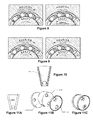
- FIG. 6 shows an expansion force being applied on a piston of an embodiment of the toroidal engine of the present invention
- FIG. 7 shows a comparison of an ideal simplified model of the torque between a reciprocating internal combustion engine and an embodiment of the toroidal engine of the present invention
- FIGS. 8 and 9 show examples of one-way bearings that can be used in an embodiment of the toroidal engine of the present invention.
- FIG. 10 show an embodiment of a piston for an embodiment of the toroidal engine of the present invention.
- FIGS. 11A-11C show another embodiment of a piston for an embodiment of the toroidal engine of the present invention.
- FIGS. 12A-12C show another embodiment, and portions thereof, of the toroidal engine of the present invention.
- FIG. 13 shows a block diagram representing a toroidal engine of the present invention with a system to alternately stop the cranks and time the ignition;
- FIGS. 14A-14C show a ring with interference structures formed thereon
- FIGS. 15A-15D show yet another embodiment, and portions thereof, of the toroidal engine of the present invention.
- FIG. 16 shows a side cross-sectional view of a mechanical assembly used in an embodiment of the present invention
- FIG. 17 shows a block diagram of an example of a system that can be used in embodiments of the present invention.
- FIG. 18 shows an embodiment of an electrical circuit that can be used in embodiments of the present invention.
- the present invention provides a toroidal engine.
- the toroidal engine can be a toroidal internal combustion engine powered by a fuel/air mixture, or a toroidal pneumatic engine powered by a compressed gas source.
- the toroidal engine uses one-way bearings to transfer torque generated in a toroidal chamber directly to a drive shaft. Pairs of pistons are mounted on two crank assemblies, which are concentric with the drive shaft. One-way bearing assemblies allow the crank assemblies to turn, one at a time, in one direction only and to latch onto the drive shaft to turn the drive shaft.
- the crank assemblies are directly coupled to the drive shaft, which eliminates the need for complex gear and linkage arrangements.
- the present invention further provides, for the toroidal engine powered by a fuel/air mixture, a mechanical fuel ignition timing mechanism, and, for the toroidal engine powered by a compressed gas source, an air injection timing mechanism.
- FIG. 2 shows an exploded view of components comprised in an exemplary embodiment of a toroidal internal combustion engine of the present invention.
- the toroidal internal combustion engine can also be referred to as a Rotational Impact Internal Combustion Engine (RIICE).
- FIG. 2 shows two cranks 100 a and 100 b , each crank having secured thereto two diametrically disposed pistons 102 a and 102 b respectively.
- Each crank ( 100 a , 100 b ) and its respective pistons ( 102 a , 102 b ) can be referred to as a crank assembly.
- Each piston 102 a is interposed between two pistons 102 b and, each piston 102 b is interposed between two pistons 102 a .
- Each crank can include an impact ring 112 that prevents the pistons 102 a from hitting the pistons 102 b .
- the impact rings are designed to prevent damage to the pistons and to promote energy transfer between them during start up as well as to transfer kinetic energy between the cranks when the engine is in operation.
- each impact ring 112 has a pair of wedge-shaped protrusions 113 , each protrusion having an angular width larger than that of the pistons, to prevent the pistons 102 a from directly impacting the pistons 102 b .
- Each impact ring 112 can be secured to its respective crank through any suitable means such as, for example, fasteners.
- the pistons 102 a and 102 b can be secured to their respective cranks 100 a and 100 b by screws or any other suitable fasteners.
- each crank ( 100 a , 100 b ) in the exemplary embodiment on FIG. 2 is shown as having two pistons ( 102 a , 102 b ), any suitable number of pistons secured to each crank is also within the scope of the present invention.
- Also shown at FIG. 2 is a drive shaft 104 and indexing one-way bearings 106 a and 106 b .
- the indexing one-way bearings 106 a and 106 b which can also be referred to as driving one-way bearings, are disposed over the drive shaft 104 .
- Sleeves 108 a and 108 b are disposed over, and fixedly secured to, respective indexing one-way bearings 106 a and 106 b .
- Backstopping one-way bearings 110 a and 110 b are disposed over respective sleeves 108 a and 108 b .
- the backstopping one-way bearings 110 a and 110 b fit in holes 114 defined in pillow block 116 a and 116 b , and are fixedly secured to their respective pillow block, which can also be referred to as a bearing housing.
- the sleeve 108 a and 108 b fit in bores 111 , which can also be referred to as circular bores or holes, defined in each crank 100 a and 100 b .
- the impact rings 112 each have a bore 111 ′.
- the drive shaft 104 extends through the bores 111 and 111 ′.
- Each crank 100 a and 100 b is fixedly secured to respective sleeves 108 a and 108 b through any suitable means such as, for example, keyways, interference fit, press-fit, etc.
- the bores 111 ′ in the impact rings 112 is for clearance around the drive shaft 104 .
- the bores 111 ′ are smaller than the bores 111 in the cranks, but larger than the diameter of the drive shaft 104 . Therefore, the impact rings 112 can also act as a shoulder on their respective crank to hold the sleeves axially, as the sleeves are tightened inwards by pillow blocks.
- the exemplary toroidal internal combustion engine of FIG. 2 can be secured to any suitable framework through mounts (not shown).
- the pillow blocks 116 a and 116 b can also be used to house external radial ball bearings. These radial ball bearings take the radial load applied to the indexing and backstopping one-way bearings and they keep the drive shaft true with respect to the cranks and one-way bearings.
- FIG. 3 shows an end view of the pillow block 116 b .
- FIG. 4 shows a cross-sectional view of the toroidal internal combustion engine of FIG. 2 with a front casing 118 and a back casing 120 disposed over respective cranks 100 b and 100 a . Also shown at FIG. 4 is an inner seal 124 , an outer seal 122 , and a radial ball bearing 126 .
- the cranks 100 a and 100 b , the front casing 118 and the back casing 120 define a toroidal chamber in which the pistons 102 a and 102 b can rotate about the drive shaft 104 .
- the front casing 118 , the back casing 120 can be said to form the housing of the exemplary internal combustion engine shown at FIGS.
- the pillow blocks 116 a and 116 b can be fixedly secured, for example, through any suitable fasteners, to the housing.
- any suitable fasteners to the housing.
- FIGS. 2-4 are shown as having two sleeves per crank assembly, any suitable number of sleeves can be used without departing from the scope of the present invention.
- the backstopping one-way bearings 110 a and 110 b have their outside perimeter fixedly secured to their respective pillow blocks 116 a and 116 b . That is, the outside race structure of the backstopping one-way bearings 110 a and 110 b are fixedly secured to their respective pillow blocks 116 a and 116 b . This can be achieved, for example, by press-fitting the backstopping one-way bearings into their respective pillow blocks.
- the inside perimeter of the backstopping one-way bearings 110 a and 110 b includes rollers that contact the outer perimeter of their respective sleeves 108 a and 108 b to allow their respective sleeves 108 a and 108 b , and their respective cranks 100 a and 100 b , to rotate in one and the same direction only (e.g., counterclockwise direction), and to prevent rotation in the opposite direction (e.g., clockwise direction).
- the indexing one-way bearings 106 a and 106 b (the driving one-way bearings) have their outside perimeter fixedly secured to the inner perimeter of their respective sleeves 108 a and 108 b .
- the outside race structure of the indexing one-way bearings 106 a and 106 b are fixedly secured to the inner perimeter of their respective sleeves 108 a and 108 b .
- This can be achieved, for example, by press-fitting the indexing one-way bearings 106 a and 106 b into their respective sleeves.
- the inside perimeter of the indexing one-way bearings 106 a and 106 b includes rollers that contact the drive shaft 104 and can latch onto the drive shaft 104 when their respective sleeves 108 a and 108 b rotate in the rotation direction allowed by the backstopping one-way bearings 110 a and 110 b (e.g., counterclockwise direction, as shown at FIG. 3 ).
- the inside perimeter of the indexing one-way bearing 106 a and 106 b allow the drive shaft 104 to rotate when their respective sleeves 108 a and 108 b are immobile with respect to their respective pillow blocks 116 a and 116 b , i.e., with respect to the housing of the internal combustion engine.
- each crank 100 a and 100 b (crank assembly 100 a/ 102 a , crank assembly 100 b/ 102 b ) overlaps, at least partially, one of the indexing one-way bearings 106 a and 106 b respectively. This also allows for an internal combustion engine with smaller dimensions.
- FIGS. 5A-5F show how the toroidal internal combustion engine exemplary embodiment of FIGS. 2-4 functions.
- the toroidal chamber has four variable volume compartments 1 , 2 , 3 , and 4 , each such compartment being comprised between adjacent pairs of pistons.
- FIG. 5A shows the toroidal chamber 127 .
- Pistons 102 a are secured to crank 100 a
- pistons 102 b are secured to crank 100 b .
- a compressed fuel/air mixture 128 present in a section of the toroidal chamber 127 and comprised between the topmost pistons 102 a and 102 b , is ignited by a spark unit 130 , which can also be referred to as an ignition unit, which can include, for example, a spark plug.
- the section of the toroidal chamber 127 comprised between the topmost pistons 102 a and 102 b , that is the section of the toroidal chamber in which the fuel/air mixture is ignited and combusts, can be referred to as the combustion compartment.
- the topmost piston 102 a can be referred to as the back piston, and the topmost piston 102 b can be referred to as the front piston.
- the spark unit 130 can be secured to an opening defined, for example, in the front casing 118 or the back casing 120 . As such, the spark unit 130 can ignite the fuel/air mixture 128 present in the combustion compartment. The explosion of the fuel/air mixture 128 causes a force to develop between the topmost pistons 102 a and 102 b.
- the backstopping one-way bearing 110 a ( FIGS. 2-4 ) disposed between the sleeve 108 a , to which the crank 100 a is fixedly secured, and its respective pillow block 116 a , prevents the crank 100 a and its pistons 102 a from rotating in one direction (clockwise direction in FIG. 4 ) upon action of the aforementioned force.
- pistons 102 b and the crank 100 b to which they are secured are allowed to rotate in the opposite direction (counterclockwise direction in FIG. 4 ) upon action of the force.
- FIG. 5B shows, at reference numeral 132 , the expansion of the exploded fuel/air mixture. That is, the variable volume compartment (combustion compartment) defined in the toroidal chamber, between the two topmost pistons of FIG. 5A ( 102 b , 102 a ), is shown, at FIG. 5B , as expanded relative to its configuration of FIG. 5A .
- FIG. 5C shows, at reference numeral 134 , how the combustion products resulting from a fuel/air mixture ignition having occurred immediately before that shown at FIG. 5A are evacuated through an exhaust aperture 136 .
- FIG. 5D shows, how a fresh fuel/air mixture is drawn into the toroidal chamber 127 through an intake aperture 140 .
- FIGS. 5E shows, at reference numeral 142 , how a fresh fuel/air mixture inserted into the toroidal chamber through intake 140 , during the previous internal combustion cycle is compressed.
- FIG. 5E Upon compression of the fresh fuel/air mixture at 142 ( FIG. 5E ), pressure will build up being the topmost piston 102 b and the topmost piston 102 a will move in the counterclockwise direction beyond the spark unit 130 . This is shown at FIG. 5F . At that point, ignition of the fresh fuel/air mixture occurs and the process shown at FIGS. 5B-5E repeats.
- one set of pistons can rotate approximately 170° during one cycle, while the other set can rotate about 10°.
- FIGS. 5A-5F shows that the piston 102 b with the black dot has rotated 170° while the pistons 102 a have rotated 10°.
- the toroidal internal combustion engine embodiment of the present toroidal engine invention can be powered by any suitable fuel.
- the toroidal internal combustion engine embodiment as shown in the embodiment of FIGS. 5A-5F , could be powered by, gasoline, ethanol, hydrogen or any other appropriate fuel that can be provided to the engine though the intake 140 .
- the exemplary toroidal engine of FIGS. 5A-5F could be adapted to be powered by diesel fuel through simple modifications including, for example, replacing the spark unit 130 with a diesel fuel injector and providing a glow plug to warm the combustion chamber and providing air through the intake 136 .
- FIGS. 5C Although the present invention has been thus far described in relation to toroidal internal combustion engine embodiments, the skilled worker will appreciate that replacing the spark unit 130 with a compressed gas source would enable the present invention to function as a toroidal pneumatic engine.
- the exhaust port 136 of FIG. 5C would still be functional, allowing low pressure air to exhaust to atmosphere after each impulse of air.
- the intake port 140 would draw air in from the atmosphere to be compressed during the compression stroke as described above. Such compressed air would facilitate the rotation of the back piston of the previous cycle, now the forward piston, into the “ignition” position (compressed gas intake position in the toroidal pneumatic engine embodiment).
- 5G-5I show another embodiment of a toroid pneumatic engine 898 that has two exhaust ports 900 and two compressed air inputs 902 .
- the compressed air inputs provide compressed air to the toroid engine 898 in accordance with a respective valve 904 (e.g., a solenoid valve), which can be opened and closed by a controller.
- a respective valve 904 e.g., a solenoid valve
- FIG. 6 and FIG. 7 show the advantage, in terms of torque, of the toroidal internal combustion engine embodiment of the present toroidal engine invention over conventional internal combustion engines such as the one shown at FIG. 1 .
- the expansion force caused by the ignition of the fuel/air mixture is always substantially perpendicular to the piston.
- the torque is constant throughout the entire length of the stroke (about 170° in the present embodiment).
- FIG. 7 which compares the torques of a conventional internal combustion engine (half sine wave-reciprocating IC engine) to the toroidal internal combustion engine of the present invention (straight line toroidal internal combustion engine of the present invention, as exemplified at FIGS. 5A-5F ) over a full stroke length.
- FIG. 7 does not take into account frictional losses or thermodynamic cycle.
- indexing one-way bearings can be used in toroidal internal combustion engine and toroidal pneumatic engine embodiments of the present invention.
- One-way bearings work on the principle of opposite relative motion. If no opposite motion exists between a drive shaft and a housing, the one-way bearing is overrunning and does not transmit torque, either from the drive shaft to the housing or from the housing to the drive shaft. With respect to FIG. 8 and FIG. 9 , obtained from Torrington Service Catalogue (2001), when opposite relative motion exist between the shaft (drive shaft) and housing, the one-way bearing latches to the drive shaft and begins transmitting torque between the drive shaft and the housing.
- rollers When opposite relative motion is applied either to the shaft or housing, the rollers climb their respective ramp and eliminate any clearance that existed between the shaft, rollers and housing. Without any clearance, the rollers can no long rotate, thereby forming a solid link between the shaft and housing.
- This type of one-way bearing can require a hardened and precisely ground shaft to prevent substantial damage to the shaft and to the bearing.
- one-way bearings serve two fundamental functions in the toroidal engine of the present invention.
- the backstopping one-way bearings e.g., 110 a , which has its rollers in direct physical contact with the outer perimeter of the sleeve 108 a and its outer race structure fixedly secured to the pillow block 116 a
- the reverse rotation of the back piston e.g., 102 a
- the expanding combusting fuel/air mixture fills the space between the topmost pistons 102 a and 102 b shown at FIG.
- each crank and piston assembly which can be referred to as a crank assembly, rotates at separate time intervals with relative motion between the two crank assemblies. That is, the two crank assemblies ( 100 a and 102 a , 100 b and 102 b ) shown in the example of FIG. 2 , rotate intermittently. The two pistons on each crank rotate with their respective crank and there is no relative motion between the pistons located on the same crank.
- the second function of the one-way bearings is to transmit the torque generated in the toroidal chamber 127 shown at FIG. 5A .
- the force of expansion on the pistons ( 102 a , 102 b ) applies torque to the drive shaft 104 .
- the cranks 100 a and 100 b transmit torque to the shaft intermittently through the indexing one-way bearings 106 a and 106 b .
- Exemplary embodiments of the internal combustion engine of the present invention is such that the individual cranks 100 a and 100 b apply torque to the drive shaft 104 separately, at different times. Indexing one-way bearings 106 a and 106 b are used to apply torque to the drive shaft 104 , yet still allowing the drive shaft 104 to continue its rotation when no torque is applied.
- the torque output of a one-way bearing will generally depend on: (a) the manufacturing tolerances; (b) the hardness of the rollers; and, (c) the diameter of the bearing.
- the diameter of the bearing limits the diameter of the rollers, and the number of rollers. Larger diameter rollers can carry larger loads, and the number of rollers increases the load capacity of the one-way bearing linearly.
- the toroidal internal combustion engine of the present invention has been described so far as comprising one-way bearings (backstopping one-way bearings and indexing (or driving) one-way bearings).
- the scope of the present invention also encompasses freewheel mechanisms, ratchet mechanisms, sprag clutch mechanisms, freewheel clutches, overrunning clutches, electromagnetic clutches, needle clutch roller bearing mechanisms, one-way locking roller bearing mechanisms, one-way needle bearing mechanisms, coaster brake mechanism, and friction plate mechanisms, that can be used instead of, or in addition to, the one-way bearing mechanisms described above.
- each piston ( 102 a and 102 b ) is designed to transfer the energy supplied by the expanding combusting fuel/air mixture to the cranks 100 a and 100 b . Additionally, each piston is designed to transfer energy from the cranks to compress the fresh air/fuel prior to combustion.
- the pistons 102 a and 102 b can have any suitable shape without departing from the scope of the present invention.
- circular face pistons can be used.
- Such circular face pistons provide the largest area with the smallest perimeter.
- the circular face pistons can be monolithic, or compound, and have a radial cross-section that is circular throughout the piston.
- Such pistons have a shape which is substantially that of a segment of toroid and can be referred to as toroid pistons.
- An example of such a piston 400 is shown at FIG. 10 .
- the circular face pistons can be a compound pistons made of a number of parts that include two discs (the two circular faces of the pistons), connected by a middle portion of arbitrary radial cross-section.
- FIGS. 11A, 11B, and 11C which show a compound piston 401
- two such circular piston faces 402 and 404 can be connected by a beveled portion 406 of a circular cylinder.
- the circular pistons faces can be secured to the beveled portion 406 through any suitable fastener.
- such compound pistons can be easier to manufacture than the aforementioned pistons that have circular radial cross-section throughout.
- the pistons 400 and 401 can be made of any suitable material, including, for example, aluminum alloys with high silicon additions such as 4032 or little silicon such as 2618.
- Aluminum can be advantageous because of its strength-to-weight ratio and relatively low cost. Silicon additions reduce the piston thermal expansion due to heat while high strength alloys such as 2618 are intended for aggressive high-power applications. Iron and steel can also be used.
- acetal and any other resilient hard plastics can be used.
- Piston rings made of any suitable material can be used to seal the perimeter of the pistons in the toroidal chamber ( 127 , FIG. 5A ).
- FIG. 12A , FIG. 12B , and FIG. 12C show an alternate embodiment the toroidal chamber internal combustion engine of the present invention.
- the internal combustion engine 500 of FIG. 12A is similar to that shown in the exploded view of FIG. 2 , but with an additional system, shown at reference numeral 522 in the block diagram of FIG. 13 .
- the system 522 alternately stops the cranks (crank assemblies) at a predetermined position and times the ignition of the fuel in the combustion compartment. Details of the system will be described further below.
- the internal combustion engine 500 has a first crank assembly 502 that includes a first crank 504 and first pistons 506 .
- the internal combustion engine 500 also includes a second crank assembly 508 that includes a second crank 510 having secured thereto second pistons 512 , only one of which is shown at FIG. 12A .
- the first crank assembly 502 and the second crank assembly 508 each have a pair of diametrically opposed pistons secured thereto.
- the internal combustion engine 500 has a housing 516 that houses the first crank assembly 502 and the second crank assembly 508 .
- the housing 516 includes a first casing 518 , a second casing 520 .
- the housing 516 can have formed thereon, or secured thereto, pillow blocks similar to pillows blocks 116 a and 116 b in the exemplary embodiment of FIG. 2 .
- the housing 516 , the first crank assembly 502 , and the second crank assembly 508 define the toroidal chamber of the internal combustion engine 500 .
- the internal combustion engine 500 comprises a drive shaft, such as drive shaft 104 shown at FIG. 2 , that is operationally coupled to the first crank assembly 502 and to the second crank assembly 508 , for example, through driving one-way bearings and sleeves such as shown at reference numerals 106 a , 106 b , 108 a , and 108 b of FIG. 2 .
- the first crank assembly 502 and the second crank assembly 508 are operationally coupled to the drive shaft to turn the drive shaft in a pre-determined direction. Also as in the example of FIG.
- the housing 516 is operationally coupled to the first crank assembly 502 and to the second crank assembly 508 to prevent the first crank assembly 502 and the second crank assembly 508 from turning in a direction opposite the pre-determined direction.
- the housing 516 can be operationally coupled to the first crank assembly 502 and to the second crank assembly 508 through backstopping one-way bearings, sleeves, and pillow blocks such as shown reference numerals 110 a , 110 b , 108 a , 108 b , 116 a , and 116 b at the example of FIG. 2 .
- each of the first crank assembly 502 and the second crank assembly 508 can have formed thereon an impact feature such as the impact ring 112 , and its protrusions 113 , shown at FIG. 2 .
- the impact ring of one crank assembly impacts the impact ring of the other crank assembly and transfers momentum thereto.
- the impact ring of the first crank assembly 502 will impact the impact ring of the second crank assembly 508 and transfer momentum thereto.
- the first crank assembly 502 may continue to rotate because, for example, increasing pressure on the backside of one of its pistons due to a fresh fuel/air mixture being compressed. This process repeats with the impact ring of the second crank assembly 508 impacting the impact ring of the first crank assembly 502 .
- the extent of this post-impact rotation of the impacting crank assembly may vary between crank assemblies and between successive impacts. This can produce unevenness in the operation of the internal combustion engine 500 in that the volume of the combustion compartment, and the amount of torque generated in the combustion compartment, may vary from impact to impact (i.e., from combustion to combustion).
- FIG. 12B shows a detailed view of feature A of FIG. 12A .
- FIG. 12C shows a detailed view of feature B of FIG. 12A .
- FIG. 14A shows a perspective view of an exemplary ring 600 that can be secured to the first crank assembly 502 .
- the ring 600 includes the protrusion 514 .
- FIG. 14B shows a top view of the ring 600 .
- FIG. 14C shows a front view of the ring 600 .
- the protrusions 514 can be formed directly on the first and second crank assemblies, instead of on the rings 600 (which have to be secured to the first and second crank assemblies) without departing from the scope of the present invention.
- FIG. 15A shows a variation of the internal combustion engine 500 of FIG. 12A .
- each of the first crank assembly 502 and the second crank assembly 508 has formed thereon a pair of interference structures that can include a land 528 with a recess 530 of any suitable shape.
- FIG. 15B shows a detailed view of feature C of FIG. 15A .
- FIG. 15 C shows a detailed view of feature D of FIG. 15A .
- FIG. 15D is a perspective view of an exemplary ring 602 that can be secured to the first crank assembly 502 .
- the ring 602 includes a land 528 and a recess 530 .
- the roller of the roller assembly 524 rolls over the land 528 and engages the recess 530 to stop the first crank assembly at the pre-determined position.
- the recesses 530 can be formed directly on the first and second crank assemblies, instead of on the rings 602 (which have to be secured to the first and second crank assemblies) without departing from the scope of the present invention.
- FIGS. 12A-12C, 14A-14C, and 15A-15D all have roller assemblies that interfere with a protrusion or a recess formed on the crank assemblies.
- alternatives embodiments that have a structure formed/secured to the housing and can interfere with a structure formed on a crank assembly to temporarily stop the crank assembly to generate an ignition signal are also within the scope of the present invention.
- FIG. 16 shows a cross-sectional view the exemplary mechanical assembly 523 of the system 522 of the example of FIG. 12A .
- the mechanical assembly 523 includes a housing 798 and rod 800 to which is secured a roller assembly 524 .
- a rod guide 801 guides the rod 800 as the roller assembly 802 moves in and out of interference with the interference structures of a cranks assembly.
- a screw 803 is screwed into the rod. The screw passes through a channel 804 defined in the housing 798 .
- the channel 804 allows the rod and its roller assembly to slide back and forth as the roller assembly 524 moves in and out of interference with the interference structures of a cranks assembly.
- the rod 800 and its roller assembly 524 are biased by a spring 804 disposed between the rod guide 801 and a washer 806 which interferes with the screw 803 .
- the tension is the spring 804 is adjustable through a set screw 799 .
- a switching device can be coupled to the rod/roller assembly such that the rod/roller assembly actuate the switch every time the roller assembly interferes with an interference structure formed on the respective crank assembly.
- crank assemblies Alternatives to the mechanical assembly 523 , its roller assembly 524 , and interference structures formed on the crank assemblies are also within the scope of the present invention.
- a pair of roller assemblies formed on crank and designed to interfere with a fixed interference structure formed on the housing is within the scope of the present invention.
- roller assemblies such as the roller assembly 524 also constitute interference structures.
- any suitable interference structure formed on a crank that can interfere with a complementary interference structure formed on the housing to stop the crank at a pre-determined position and generate an electrical signal to energize an ignition unit is within the scope of the present invention.
- stiffness and damping in line with the drive shaft is the spring and friction in the mechanical assembly, and the stiffness and damping perpendicular to the drive shaft is in the deformable material of the roller.
- the angle of the stiffness and damping can be changed by changing the angle that the roller assembly is mounted on the pillow block.
- FIG. 17 shows a block diagram view of an example of the system 522 .
- the system 522 includes a mechanical assembly 523 - 1 connected to a switch 550 - 1 , both of which operationally connected to the first crank assembly 502 .
- the system also includes a mechanical assembly 523 - 2 connected to a switch 550 - 2 , both of which are operationally connected to the second crank assembly 508 .
- the switches 550 - 1 and 550 - 2 are electrically connected to an electrical circuit 552 .
- the electrical circuit 552 is electrically connected to a solenoid valve 554 that controls the intake of fuel in the internal combustion engine. The solenoid valve if to open and close the intake 140 shown at FIG. 5C .
- the electrical circuit 552 is also electrically connected to the spark unit 130 .
- the mechanical assemblies 523 - 1 and 523 - 2 of the present examples can be the same as the mechanical assembly 523 described above.
- the roller assembly 524 of the mechanical assembly 523 - 1 interfering with an interference structure formed on the first crank assembly (e.g. interference structure 514 of FIG. 12A )
- the roller assembly and its rod 800 and roller assembly 524 will be pushed and will actuate the switch 550 - 1 .
- the actuation of the switch signals the electrical circuit 552 to open the solenoid valve 554 to provide a fuel/air mixture to the internal combustion engine.
- the actuation of the switch 550 - 1 also signals the electrical circuit 552 to ignite the spark unit 130 .
- the disposition of the switch 550 - 1 relative to the roller mechanism (its rod 800 ) can be adjusted in accordance to a pre-determined time delay required to ignite the spark unit 130 that optimizes the performance of the internal combustion engine. Additionally, or alternatively, the electrical circuit may contain elements to enable the adjustment of the time delay.
- the roller assembly 524 of the mechanical assembly 523 - 2 interfering with an interference structure formed on the second crank assembly e.g. interference structure 514 of FIG. 12A
- the roller assembly 524 and its rod 800 will be pushed and will actuate the switch 550 - 2 .
- the actuation of the switch signals the electrical circuit 552 to open the solenoid valve 554 to provide a fuel/air mixture to the internal combustion engine.
- the actuation of the switch 550 - 2 also signals the electrical circuit 552 to ignite the spark unit 130 .
- the disposition of the switch 550 - 2 relative to the roller mechanism (its rod 800 ) can be adjusted in accordance to a pre-determined time delay required to ignite the spark unit 130 that optimizes the performance of the internal combustion engine.
- a plurality of toroidal internal combustion engines of the present invention can be disposed in series to provide torque to a same drive shaft.
- the design of the toroidal internal combustion engine of the present invention has a small number of moving parts, including two crank/pistons/sleeve assemblies, one drive shaft, and a series of bearing assemblies.
- Conventional internal combustion engines have a large number of moving parts. By using the toroidal internal combustion engine of the present invention in, for example, hybrid technology, the total number of moving parts would be significantly decreased.
Landscapes
- Engineering & Computer Science (AREA)
- Mechanical Engineering (AREA)
- General Engineering & Computer Science (AREA)
- Chemical & Material Sciences (AREA)
- Combustion & Propulsion (AREA)
- Rolling Contact Bearings (AREA)
- Transmission Devices (AREA)
Abstract
Description
T=rF(θ)≅rF sin(θ) (Equation 1)
T=rF (Equation 2)
Claims (9)
Priority Applications (1)
| Application Number | Priority Date | Filing Date | Title |
|---|---|---|---|
| US14/228,053 US9890701B2 (en) | 2010-02-04 | 2014-03-27 | Toroidal engine |
Applications Claiming Priority (3)
| Application Number | Priority Date | Filing Date | Title |
|---|---|---|---|
| US30143610P | 2010-02-04 | 2010-02-04 | |
| US12/916,979 US8695564B2 (en) | 2010-02-04 | 2010-11-01 | Toroidal engine |
| US14/228,053 US9890701B2 (en) | 2010-02-04 | 2014-03-27 | Toroidal engine |
Related Parent Applications (1)
| Application Number | Title | Priority Date | Filing Date |
|---|---|---|---|
| US12/916,979 Division US8695564B2 (en) | 2010-02-04 | 2010-11-01 | Toroidal engine |
Publications (2)
| Publication Number | Publication Date |
|---|---|
| US20140294646A1 US20140294646A1 (en) | 2014-10-02 |
| US9890701B2 true US9890701B2 (en) | 2018-02-13 |
Family
ID=44340498
Family Applications (2)
| Application Number | Title | Priority Date | Filing Date |
|---|---|---|---|
| US12/916,979 Expired - Fee Related US8695564B2 (en) | 2010-02-04 | 2010-11-01 | Toroidal engine |
| US14/228,053 Expired - Fee Related US9890701B2 (en) | 2010-02-04 | 2014-03-27 | Toroidal engine |
Family Applications Before (1)
| Application Number | Title | Priority Date | Filing Date |
|---|---|---|---|
| US12/916,979 Expired - Fee Related US8695564B2 (en) | 2010-02-04 | 2010-11-01 | Toroidal engine |
Country Status (2)
| Country | Link |
|---|---|
| US (2) | US8695564B2 (en) |
| CA (1) | CA2719631A1 (en) |
Cited By (1)
| Publication number | Priority date | Publication date | Assignee | Title |
|---|---|---|---|---|
| US20220056752A1 (en) * | 2020-08-24 | 2022-02-24 | Hyundai Motor Company | System for controlling power tail gate of vehicle and method for controlling thereof |
Families Citing this family (16)
| Publication number | Priority date | Publication date | Assignee | Title |
|---|---|---|---|---|
| US20120266841A1 (en) * | 2011-04-25 | 2012-10-25 | Seyd Mehdi Sobhani | Rice, ricg, & rc |
| JP6022757B2 (en) * | 2011-10-31 | 2016-11-09 | ナブテスコ株式会社 | Rotary actuator |
| US8931455B2 (en) * | 2012-03-23 | 2015-01-13 | Boots Rolf Hughston | Rotary engine |
| WO2014085905A1 (en) * | 2012-12-03 | 2014-06-12 | Dalhousie University | Dual rotor impact rings |
| WO2016145440A1 (en) * | 2015-03-12 | 2016-09-15 | Hicks Edward Alan | Motor/engine with rotating pistons |
| US9464675B1 (en) * | 2015-04-10 | 2016-10-11 | Schaeffler Technologies AG & Co. KG | Wedge friction one-way clutch with controllable clutch locking function |
| FR3038939B1 (en) * | 2015-06-26 | 2019-04-19 | Valeo Systemes Thermiques | PISTON FIXING DEVICE FOR COMPRESSION AND RELIEF MACHINE |
| US9982593B1 (en) * | 2015-07-27 | 2018-05-29 | Aman Srivastava | Internal combustion butterfly engine |
| WO2019027400A2 (en) * | 2017-04-20 | 2019-02-07 | Istanbul Teknik Universitesi | Internal combustion engine with a rotating piston and uni-directional rolling bear |
| US10801401B2 (en) * | 2017-10-12 | 2020-10-13 | Constant Velocity Design Llc | Toroidal engine |
| US11820502B2 (en) * | 2018-04-24 | 2023-11-21 | Airbus Operations Gmbh | Wing for an aircraft |
| WO2021070199A1 (en) * | 2019-10-07 | 2021-04-15 | Vipulkumar Dhirubhai Patel | An internal combustion engine |
| JP7553276B2 (en) * | 2020-07-27 | 2024-09-18 | Ntn株式会社 | Bearing device |
| RU2753083C1 (en) * | 2021-01-20 | 2021-08-11 | Андрей Степанович Галицкий | Internal combustion engine |
| KR102452601B1 (en) | 2021-05-28 | 2022-10-06 | 두산에너빌리티 주식회사 | Large capacity Hydrodynamic type Dynamometer having output control mechanism |
| US12221920B1 (en) * | 2024-03-19 | 2025-02-11 | John Edward Kleindienst | Cam following system for pursing piston engine |
Citations (29)
| Publication number | Priority date | Publication date | Assignee | Title |
|---|---|---|---|---|
| US1212649A (en) | 1915-12-07 | 1917-01-16 | Mardiros Asadoor Krikorian | Rotary engine. |
| US1298839A (en) | 1917-05-11 | 1919-04-01 | Howard L Weed | Rotary engine. |
| US1790534A (en) | 1931-01-27 | Valveless internal combustion engine | ||
| US1973397A (en) | 1929-10-14 | 1934-09-11 | Olof E E Stromberg | Rotary engine |
| US3186383A (en) | 1962-11-28 | 1965-06-01 | Potters Insulations Ltd | Internal combustion engines |
| US3251347A (en) | 1963-11-26 | 1966-05-17 | Norman E Farb | Internal combustion engine |
| US3381669A (en) | 1966-10-31 | 1968-05-07 | Tschudi Engine Corp | Rotary internal combustion engine |
| US3909162A (en) | 1970-12-03 | 1975-09-30 | Ata Nutku | Toroidal chamber rotating piston machine |
| US3990405A (en) * | 1975-01-16 | 1976-11-09 | Joseph Kecik | Rotary internal combustion engine |
| US4035111A (en) | 1975-08-06 | 1977-07-12 | Cronen Sr Peter J | Toroidal rotary engine |
| US4319551A (en) | 1979-02-06 | 1982-03-16 | Bernard Rubinshtein | Rotary internal combustion engine |
| US5009206A (en) | 1989-11-16 | 1991-04-23 | Yi Chong S | Rotary internal combustion engine |
| US5046465A (en) | 1989-08-16 | 1991-09-10 | Yi Chong S | Rotary internal combustion engine |
| US5199391A (en) | 1991-11-08 | 1993-04-06 | Kovalenko Gerald E | Toroidal internal combustion engine |
| US5222463A (en) | 1992-07-23 | 1993-06-29 | Monti Farrell | Oscillating piston engine |
| US5224847A (en) * | 1992-01-31 | 1993-07-06 | Mikio Kurisu | Rotary engine |
| US5242288A (en) | 1987-09-14 | 1993-09-07 | Vincent Ogden W | Rotary engine or pump with a round toroidal cylinder and pistons |
| US5622149A (en) | 1993-12-02 | 1997-04-22 | Wittry; David B. | High-power rotary engine with varaiable compression ratio |
| US6158987A (en) * | 1998-01-13 | 2000-12-12 | Raikamo; Esko | Power unit for use as a pressure-fluid operated motor and/or a pressure fluid pump |
| US6257196B1 (en) * | 1999-09-07 | 2001-07-10 | Alfredo Alvarado | Rotary disc engine |
| US6321693B1 (en) * | 1998-12-02 | 2001-11-27 | Chang Kyun Kim | Reciprocating rotary piston system and pressure pump and internal combustion engine using the same |
| US6341590B1 (en) | 2001-12-17 | 2002-01-29 | BARRERA RENé MANUEL | Rotary engine |
| WO2003083276A1 (en) | 2002-03-26 | 2003-10-09 | Ralph Gordon Morgado | Internal combustion engine and method |
| CA2533496A1 (en) | 2003-07-22 | 2005-02-03 | Karl V. Hoose | Toroidal internal combustion engine |
| US6895922B1 (en) | 2004-08-09 | 2005-05-24 | Gloria Snowden-Wood | Rotary opposed piston engine |
| US20050207687A1 (en) * | 2002-01-21 | 2005-09-22 | Nsk Ltd. | Rolling bearing |
| US7059294B2 (en) | 2004-05-27 | 2006-06-13 | Wright Innovations, Llc | Orbital engine |
| US7182061B2 (en) * | 2004-10-04 | 2007-02-27 | Petrica Lucian Georgescu | Rotary internal combustion engine |
| US7222601B1 (en) * | 2005-07-08 | 2007-05-29 | Kamen George Kamenov | Rotary valveless internal combustion engine |
-
2010
- 2010-11-01 US US12/916,979 patent/US8695564B2/en not_active Expired - Fee Related
- 2010-11-01 CA CA2719631A patent/CA2719631A1/en not_active Abandoned
-
2014
- 2014-03-27 US US14/228,053 patent/US9890701B2/en not_active Expired - Fee Related
Patent Citations (34)
| Publication number | Priority date | Publication date | Assignee | Title |
|---|---|---|---|---|
| US1790534A (en) | 1931-01-27 | Valveless internal combustion engine | ||
| US1212649A (en) | 1915-12-07 | 1917-01-16 | Mardiros Asadoor Krikorian | Rotary engine. |
| US1298839A (en) | 1917-05-11 | 1919-04-01 | Howard L Weed | Rotary engine. |
| US1973397A (en) | 1929-10-14 | 1934-09-11 | Olof E E Stromberg | Rotary engine |
| US3186383A (en) | 1962-11-28 | 1965-06-01 | Potters Insulations Ltd | Internal combustion engines |
| US3251347A (en) | 1963-11-26 | 1966-05-17 | Norman E Farb | Internal combustion engine |
| US3381669A (en) | 1966-10-31 | 1968-05-07 | Tschudi Engine Corp | Rotary internal combustion engine |
| US3909162A (en) | 1970-12-03 | 1975-09-30 | Ata Nutku | Toroidal chamber rotating piston machine |
| US3990405A (en) * | 1975-01-16 | 1976-11-09 | Joseph Kecik | Rotary internal combustion engine |
| US4035111A (en) | 1975-08-06 | 1977-07-12 | Cronen Sr Peter J | Toroidal rotary engine |
| US4319551A (en) | 1979-02-06 | 1982-03-16 | Bernard Rubinshtein | Rotary internal combustion engine |
| US5242288A (en) | 1987-09-14 | 1993-09-07 | Vincent Ogden W | Rotary engine or pump with a round toroidal cylinder and pistons |
| US5046465A (en) | 1989-08-16 | 1991-09-10 | Yi Chong S | Rotary internal combustion engine |
| US5009206A (en) | 1989-11-16 | 1991-04-23 | Yi Chong S | Rotary internal combustion engine |
| US5199391A (en) | 1991-11-08 | 1993-04-06 | Kovalenko Gerald E | Toroidal internal combustion engine |
| US5224847A (en) * | 1992-01-31 | 1993-07-06 | Mikio Kurisu | Rotary engine |
| US5222463A (en) | 1992-07-23 | 1993-06-29 | Monti Farrell | Oscillating piston engine |
| US5303546A (en) | 1992-07-23 | 1994-04-19 | Monti Farrell | Oscillating piston engine for driving a ducted fan |
| US5323737A (en) | 1992-07-23 | 1994-06-28 | Monti Farrell | Electrical charging system for an electric powered vehicle |
| US5324176A (en) | 1992-07-23 | 1994-06-28 | Monti Farrell | Oscillating piston engine for pumping system |
| US5467744A (en) | 1992-07-23 | 1995-11-21 | Farrell; Monti | Oscillating piston engine for helicopters |
| US5622149A (en) | 1993-12-02 | 1997-04-22 | Wittry; David B. | High-power rotary engine with varaiable compression ratio |
| US6158987A (en) * | 1998-01-13 | 2000-12-12 | Raikamo; Esko | Power unit for use as a pressure-fluid operated motor and/or a pressure fluid pump |
| US6321693B1 (en) * | 1998-12-02 | 2001-11-27 | Chang Kyun Kim | Reciprocating rotary piston system and pressure pump and internal combustion engine using the same |
| US6257196B1 (en) * | 1999-09-07 | 2001-07-10 | Alfredo Alvarado | Rotary disc engine |
| US6341590B1 (en) | 2001-12-17 | 2002-01-29 | BARRERA RENé MANUEL | Rotary engine |
| US20050207687A1 (en) * | 2002-01-21 | 2005-09-22 | Nsk Ltd. | Rolling bearing |
| WO2003083276A1 (en) | 2002-03-26 | 2003-10-09 | Ralph Gordon Morgado | Internal combustion engine and method |
| US6739307B2 (en) | 2002-03-26 | 2004-05-25 | Ralph Gordon Morgado | Internal combustion engine and method |
| CA2533496A1 (en) | 2003-07-22 | 2005-02-03 | Karl V. Hoose | Toroidal internal combustion engine |
| US7059294B2 (en) | 2004-05-27 | 2006-06-13 | Wright Innovations, Llc | Orbital engine |
| US6895922B1 (en) | 2004-08-09 | 2005-05-24 | Gloria Snowden-Wood | Rotary opposed piston engine |
| US7182061B2 (en) * | 2004-10-04 | 2007-02-27 | Petrica Lucian Georgescu | Rotary internal combustion engine |
| US7222601B1 (en) * | 2005-07-08 | 2007-05-29 | Kamen George Kamenov | Rotary valveless internal combustion engine |
Cited By (2)
| Publication number | Priority date | Publication date | Assignee | Title |
|---|---|---|---|---|
| US20220056752A1 (en) * | 2020-08-24 | 2022-02-24 | Hyundai Motor Company | System for controlling power tail gate of vehicle and method for controlling thereof |
| US12054979B2 (en) * | 2020-08-24 | 2024-08-06 | Hyundai Motor Company | System for controlling power tail gate of vehicle and method for controlling thereof |
Also Published As
| Publication number | Publication date |
|---|---|
| US20140294646A1 (en) | 2014-10-02 |
| CA2719631A1 (en) | 2011-08-04 |
| US8695564B2 (en) | 2014-04-15 |
| US20110185998A1 (en) | 2011-08-04 |
Similar Documents
| Publication | Publication Date | Title |
|---|---|---|
| US9890701B2 (en) | Toroidal engine | |
| CN102282347B (en) | rotary piston engine | |
| RU2669434C2 (en) | Opposite piston engine of internal combustion (options) and opposite internal combustion engine | |
| US9157323B2 (en) | Oscillatory rotary engine | |
| US8776759B2 (en) | Rotary internal combustion engine | |
| NZ568316A (en) | Rotary internal combustion engine with vanes having roller cams which follow the rotor | |
| US20090056667A1 (en) | Ultra Efficient Engine | |
| EP0801709A1 (en) | Orbiting piston combustion engine | |
| US9850759B2 (en) | Circulating piston engine | |
| US11215112B2 (en) | Circulating piston engine | |
| KR950006214A (en) | 4-cycle piston type internal combustion engine | |
| US3923018A (en) | Compact rotating internal combustion engine | |
| US20170089201A1 (en) | Hybrid pneumatic / internal combustion rotary engine | |
| US11428150B2 (en) | System and method for rotational combustion engine | |
| US20070137609A1 (en) | True rotary internal combustion engine | |
| WO1993016273A1 (en) | Rotary engine | |
| US6675753B2 (en) | Cam phase variable apparatus | |
| WO2020141553A1 (en) | A radial opposed piston reciprocating internal combustion engine | |
| RU2011865C1 (en) | Rotor-piston power plant | |
| US20140182542A1 (en) | Circulating Piston Engine | |
| KR200424326Y1 (en) | Cam engine | |
| US10190414B2 (en) | Round internal combustion engine | |
| CA2743062A1 (en) | Rotary external combustion engine | |
| JP3167619U (en) | Prime mover | |
| US20060120895A1 (en) | Rotary positive displacement engine |
Legal Events
| Date | Code | Title | Description |
|---|---|---|---|
| AS | Assignment |
Owner name: DALHOUSIE UNIVERSITY, CANADA Free format text: ASSIGNMENT OF ASSIGNORS INTEREST;ASSIGNORS:MURPHY, BRADEN;MARTAKOUSH, AZIZ;KRAJEWSKI, ADAM;AND OTHERS;SIGNING DATES FROM 20140401 TO 20140528;REEL/FRAME:032996/0960 |
|
| AS | Assignment |
Owner name: ATLANTIC MOTOR LABS INC., CANADA Free format text: ASSIGNMENT OF ASSIGNORS INTEREST;ASSIGNOR:DALHOUSIE UNIVERSITY;REEL/FRAME:036706/0480 Effective date: 20150508 |
|
| AS | Assignment |
Owner name: MONASHEE PUMPS INC., CANADA Free format text: CHANGE OF NAME;ASSIGNOR:ATLANTIC MOTOR LABS INC.;REEL/FRAME:042981/0086 Effective date: 20170207 |
|
| STCF | Information on status: patent grant |
Free format text: PATENTED CASE |
|
| FEPP | Fee payment procedure |
Free format text: MAINTENANCE FEE REMINDER MAILED (ORIGINAL EVENT CODE: REM.); ENTITY STATUS OF PATENT OWNER: SMALL ENTITY |
|
| LAPS | Lapse for failure to pay maintenance fees |
Free format text: PATENT EXPIRED FOR FAILURE TO PAY MAINTENANCE FEES (ORIGINAL EVENT CODE: EXP.); ENTITY STATUS OF PATENT OWNER: SMALL ENTITY |
|
| STCH | Information on status: patent discontinuation |
Free format text: PATENT EXPIRED DUE TO NONPAYMENT OF MAINTENANCE FEES UNDER 37 CFR 1.362 |
|
| FP | Lapsed due to failure to pay maintenance fee |
Effective date: 20220213 |