US9873174B2 - Turning controller - Google Patents
Turning controller Download PDFInfo
- Publication number
- US9873174B2 US9873174B2 US14/963,243 US201514963243A US9873174B2 US 9873174 B2 US9873174 B2 US 9873174B2 US 201514963243 A US201514963243 A US 201514963243A US 9873174 B2 US9873174 B2 US 9873174B2
- Authority
- US
- United States
- Prior art keywords
- approach angle
- axis
- tool
- command value
- turning
- Prior art date
- Legal status (The legal status is an assumption and is not a legal conclusion. Google has not performed a legal analysis and makes no representation as to the accuracy of the status listed.)
- Active, expires
Links
Images


Classifications
-
- B—PERFORMING OPERATIONS; TRANSPORTING
- B23—MACHINE TOOLS; METAL-WORKING NOT OTHERWISE PROVIDED FOR
- B23Q—DETAILS, COMPONENTS, OR ACCESSORIES FOR MACHINE TOOLS, e.g. ARRANGEMENTS FOR COPYING OR CONTROLLING; MACHINE TOOLS IN GENERAL CHARACTERISED BY THE CONSTRUCTION OF PARTICULAR DETAILS OR COMPONENTS; COMBINATIONS OR ASSOCIATIONS OF METAL-WORKING MACHINES, NOT DIRECTED TO A PARTICULAR RESULT
- B23Q15/00—Automatic control or regulation of feed movement, cutting velocity or position of tool or work
- B23Q15/007—Automatic control or regulation of feed movement, cutting velocity or position of tool or work while the tool acts upon the workpiece
- B23Q15/14—Control or regulation of the orientation of the tool with respect to the work
-
- B—PERFORMING OPERATIONS; TRANSPORTING
- B23—MACHINE TOOLS; METAL-WORKING NOT OTHERWISE PROVIDED FOR
- B23B—TURNING; BORING
- B23B1/00—Methods for turning or working essentially requiring the use of turning-machines; Use of auxiliary equipment in connection with such methods
-
- B—PERFORMING OPERATIONS; TRANSPORTING
- B23—MACHINE TOOLS; METAL-WORKING NOT OTHERWISE PROVIDED FOR
- B23Q—DETAILS, COMPONENTS, OR ACCESSORIES FOR MACHINE TOOLS, e.g. ARRANGEMENTS FOR COPYING OR CONTROLLING; MACHINE TOOLS IN GENERAL CHARACTERISED BY THE CONSTRUCTION OF PARTICULAR DETAILS OR COMPONENTS; COMBINATIONS OR ASSOCIATIONS OF METAL-WORKING MACHINES, NOT DIRECTED TO A PARTICULAR RESULT
- B23Q15/00—Automatic control or regulation of feed movement, cutting velocity or position of tool or work
- B23Q15/20—Automatic control or regulation of feed movement, cutting velocity or position of tool or work before or after the tool acts upon the workpiece
- B23Q15/22—Control or regulation of position of tool or workpiece
- B23Q15/26—Control or regulation of position of tool or workpiece of angular position
-
- G—PHYSICS
- G05—CONTROLLING; REGULATING
- G05B—CONTROL OR REGULATING SYSTEMS IN GENERAL; FUNCTIONAL ELEMENTS OF SUCH SYSTEMS; MONITORING OR TESTING ARRANGEMENTS FOR SUCH SYSTEMS OR ELEMENTS
- G05B19/00—Program-control systems
- G05B19/02—Program-control systems electric
- G05B19/18—Numerical control [NC], i.e. automatically operating machines, in particular machine tools, e.g. in a manufacturing environment, so as to execute positioning, movement or co-ordinated operations by means of program data in numerical form
- G05B19/404—Numerical control [NC], i.e. automatically operating machines, in particular machine tools, e.g. in a manufacturing environment, so as to execute positioning, movement or co-ordinated operations by means of program data in numerical form characterised by control arrangements for compensation, e.g. for backlash, overshoot, tool offset, tool wear, temperature, machine construction errors, load, inertia
-
- G—PHYSICS
- G05—CONTROLLING; REGULATING
- G05B—CONTROL OR REGULATING SYSTEMS IN GENERAL; FUNCTIONAL ELEMENTS OF SUCH SYSTEMS; MONITORING OR TESTING ARRANGEMENTS FOR SUCH SYSTEMS OR ELEMENTS
- G05B19/00—Program-control systems
- G05B19/02—Program-control systems electric
- G05B19/18—Numerical control [NC], i.e. automatically operating machines, in particular machine tools, e.g. in a manufacturing environment, so as to execute positioning, movement or co-ordinated operations by means of program data in numerical form
- G05B19/4093—Numerical control [NC], i.e. automatically operating machines, in particular machine tools, e.g. in a manufacturing environment, so as to execute positioning, movement or co-ordinated operations by means of program data in numerical form characterised by part programming, e.g. entry of geometrical information as taken from a technical drawing, combining this with machining and material information to obtain control information, named part program, for the NC machine
- G05B19/40937—Numerical control [NC], i.e. automatically operating machines, in particular machine tools, e.g. in a manufacturing environment, so as to execute positioning, movement or co-ordinated operations by means of program data in numerical form characterised by part programming, e.g. entry of geometrical information as taken from a technical drawing, combining this with machining and material information to obtain control information, named part program, for the NC machine concerning programming of machining or material parameters, pocket machining
-
- G—PHYSICS
- G05—CONTROLLING; REGULATING
- G05B—CONTROL OR REGULATING SYSTEMS IN GENERAL; FUNCTIONAL ELEMENTS OF SUCH SYSTEMS; MONITORING OR TESTING ARRANGEMENTS FOR SUCH SYSTEMS OR ELEMENTS
- G05B2219/00—Program-control systems
- G05B2219/30—Nc systems
- G05B2219/36—Nc in input of data, input key till input tape
- G05B2219/36204—Lathe, turning
-
- G—PHYSICS
- G05—CONTROLLING; REGULATING
- G05B—CONTROL OR REGULATING SYSTEMS IN GENERAL; FUNCTIONAL ELEMENTS OF SUCH SYSTEMS; MONITORING OR TESTING ARRANGEMENTS FOR SUCH SYSTEMS OR ELEMENTS
- G05B2219/00—Program-control systems
- G05B2219/30—Nc systems
- G05B2219/37—Measurements
- G05B2219/37344—Torque, thrust, twist, machining force measurement
-
- G—PHYSICS
- G05—CONTROLLING; REGULATING
- G05B—CONTROL OR REGULATING SYSTEMS IN GENERAL; FUNCTIONAL ELEMENTS OF SUCH SYSTEMS; MONITORING OR TESTING ARRANGEMENTS FOR SUCH SYSTEMS OR ELEMENTS
- G05B2219/00—Program-control systems
- G05B2219/30—Nc systems
- G05B2219/50—Machine tool, machine tool null till machine tool work handling
- G05B2219/50282—Tool offset as function of cutting depth
-
- Y—GENERAL TAGGING OF NEW TECHNOLOGICAL DEVELOPMENTS; GENERAL TAGGING OF CROSS-SECTIONAL TECHNOLOGIES SPANNING OVER SEVERAL SECTIONS OF THE IPC; TECHNICAL SUBJECTS COVERED BY FORMER USPC CROSS-REFERENCE ART COLLECTIONS [XRACs] AND DIGESTS
- Y02—TECHNOLOGIES OR APPLICATIONS FOR MITIGATION OR ADAPTATION AGAINST CLIMATE CHANGE
- Y02P—CLIMATE CHANGE MITIGATION TECHNOLOGIES IN THE PRODUCTION OR PROCESSING OF GOODS
- Y02P90/00—Enabling technologies with a potential contribution to greenhouse gas [GHG] emissions mitigation
- Y02P90/02—Total factory control, e.g. smart factories, flexible manufacturing systems [FMS] or integrated manufacturing systems [IMS]
-
- Y02P90/265—
Definitions
- the present invention relates to a turning controller.
- a workpiece is held on a spindle of a lathe and is thus rotated, and a tool is fed in a longitudinal direction of the workpiece (a Z-axis direction) to carry out turning work with a cutting edge of the tool cut in a predetermined cutting depth in a radial direction (an X-axis direction) of the workpiece.
- a principal force, a feed force, and a thrust force are applied to the tool.
- the thrust force is a component in a radial direction (an X-axis direction) of a cutting resistance of the workpiece, and applies a force so as to bend the workpiece in the radial direction (the X-axis direction) of the workpiece.
- Japanese Unexamined Patent Application Publication No. 2009-113143 describes designing a tool including an approach angle for causing a thrust force to be zero when a certain cutting depth is set based on knowledge that a single approach angle for causing the thrust force to be zero is defined depending on the cutting depth.
- a turning controller using a turning device, is to rotate a workpiece held on a spindle and relatively feed a tool in at least the Z-axis direction in a cutting state in a predetermined cutting depth in the X-axis direction with respect to the workpiece, thereby performing turning work.
- the turning device includes the spindle, a tool holding unit, a Z-axis driver, an X-axis driver, and a B-axis driver.
- the spindle is to be rotated together with the workpiece held thereon.
- the tool holding unit is to hold the tool to turn the workpiece.
- the Z-axis driver is to displace at least one of the spindle and the tool holding unit in a Z-axis direction which is a direction parallel to a rotation axis of the spindle.
- the X-axis driver is to displace at least one of the spindle and the tool holding unit in an X-axis direction orthogonal to the Z axis.
- the B-axis driver is to incline the tool holding unit around a Y axis orthogonal to both of the Z axis and the X axis.
- the turning controller includes a storage, a working program processing device, a command value setting processing device, an approach angle setting command amount calculator, and a command processing device.
- the storage is configured to store a working program for defining the turning work and tool shape data indicative of a shape of the tool.
- the working program processing device is configured to analyze the working program and to calculate and output command amounts for the Z-axis driver, the X-axis driver, and the B-axis driver.
- the command value setting processing device is configured to set an approach angle command value for defining an approach angle which is an angle formed by a cutting edge of the tool and a direction orthogonal to a relative feeding direction of the tool with respect to the workpiece when performing the turning work.
- the approach angle setting command amount calculator is configured to calculate, as an approach angle setting command amount, a B-axis command amount for controlling to cause the approach angle to have the approach angle command value based on the tool shape data.
- the command processing device is configured to output the approach angle setting command amount to the B-axis driver.
- the working program includes cutting depth data for defining a cutting depth and approach angle data for defining the approach angle.
- the turning controller further comprises an approach angle calculator configured to calculate an approach angle at which an absolute value of a thrust force to be applied to the workpiece by the tool is equal to or smaller than a specified value when performing the turning work according to the cutting depth data of the working program.
- the approach angle calculator is configured to register the calculated approach angle as the approach angle data into the working program.
- the command value setting processing device is configured to set the approach angle data to the approach angle command value.
- FIG. 1 is a view showing a system configuration according to an embodiment
- FIG. 2 is a perspective view showing a partial structure of a turning device according to the embodiment
- FIG. 3A is a view showing tool shape data according to the embodiment.
- FIG. 3B is a view showing a definition of the tool shape data
- FIG. 3C is a view showing a definition of a nose radius
- FIG. 4 is a view showing an approach angle
- FIGS. 5A and 5B are views showing thrust force data according to the embodiment
- FIG. 6 is a view showing tool data according to the embodiment, and furthermore, a variation of a cutting edge position with B-axis inclined in accordance with an approach angle setting command amount;
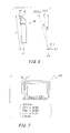
- FIG. 7 is a view showing thrust force data according to the embodiment.
- FIG. 8 is a functional block diagram showing a turning support program
- FIG. 9 is a functional block diagram related to control processing when performing turning work according to the related art.
- FIG. 10 is a flowchart showing a procedure for approach angle data set processing according to the embodiment.
- FIG. 11 is a flowchart showing a processing procedure for an approach angle calculation processing unit
- FIG. 12 is a flowchart showing a processing procedure for a determination processing unit
- FIGS. 13A and 13B are views showing a technique for determining presence or absence of interference occurrence through an approach angle according to the embodiment
- FIG. 14 is a flowchart showing a procedure for turning work processing according to the embodiment.
- FIG. 15 is a flowchart showing a processing procedure for a compensation amount calculation processing unit
- FIG. 16 is a flowchart showing a processing procedure for a command processing unit
- FIG. 17 is a flowchart showing a processing procedure for a working program processing unit
- FIG. 18 is a flowchart showing a processing procedure for angle adjustment of the approach angle according to the embodiment.
- FIG. 19 is a flowchart showing a processing procedure for an angle adjustment reception processing unit
- FIG. 20 is a flowchart showing a processing procedure for an approach angle command value storage processing unit.
- FIGS. 21A and 21B are side views showing turning work according to a variant of the embodiment.
- a turning system 20 shown in FIG. 1 is a composite working lathe system for turning a workpiece 10 .
- the turning system 20 includes a turning device 30 , a turning control device 50 , and an interface 70 .
- a cylindrical workpiece is assumed as the workpiece 10 .
- the turning device 30 includes a spindle 12 for holding the workpiece 10 , a cutting tool 36 which is a tool, and a tool holding unit 14 for holding the cutting tool 36 .
- the spindle 12 is rotatable around a rotation axis a ⁇ 1.
- the cutting tool 36 includes an insert 32 serving as a cutting edge for turning the workpiece 10 and a shank 34 for supporting the insert 32 .
- FIG. 2 shows a partial structure of the turning device 30 holding the workpiece 10 .
- the turning device 30 further has a tool holding device 16 including the tool holding unit 14 such that the tool holding unit 14 is inclinable.
- the tool holding device 16 is linearly displaceable in a Z-axis direction which is parallel to the rotation axis a ⁇ 1 and an X-axis direction which is orthogonal to a Z axis.
- the tool holding unit 14 is provided to be inclinable around an axis a ⁇ 2 which is parallel to a Y axis orthogonal to both of the Z axis and the X axis and passes through a B-axis center P 1 on the tool holding device 16 .
- the spindle 12 , the tool holding unit 14 , and the tool holding device 16 are driven by respective driving units shown in FIG. 1 .
- the turning device 30 shown in FIG. 1 includes a spindle driving unit 40 for rotating the spindle 12 around the rotation axis a ⁇ 1.
- the turning device 30 includes an X-axis driving unit 42 for displacing the tool holding device 16 in the X-axis direction and a Z-axis driving unit 44 for displacing the tool holding device 16 in the Z-axis direction.
- the tool holding device 16 is displaced in the X-axis direction so that the cutting tool 36 is also displaced in the X-axis direction
- the tool holding device 16 is displaced in the Z-axis direction so that the cutting tool 36 is also displaced in the Z-axis direction.
- the turning device 30 includes a B-axis driving unit 46 for inclining the tool holding unit 14 around the axis a ⁇ 2.
- the B-axis driving unit 46 serves to drive the B axis of the tool holding unit 14 , and the B axis is described as “B” in FIGS. 1 and 2 .
- the turning control device 50 serves as a control device for controlling the turning device 30 to carry out turning work. Specifically, the turning control device 50 calculates respective command amounts of the spindle driving unit 40 , the X-axis driving unit 42 , the Z-axis driving unit 44 , and the B-axis driving unit 46 in the turning device 30 , and outputs the calculated command amounts to the spindle driving unit 40 , the X-axis driving unit 42 , the Z-axis driving unit 44 , and the B-axis driving unit 46 , respectively.
- the command amount of the spindle driving unit 40 indicates a rotation speed of the spindle 12 .
- the command amount of the X-axis driving unit 42 indicates an X-axis direction displacement amount of the tool holding device 16 .
- the command amount of the Z-axis driving unit 44 indicates a Z-axis direction displacement amount of the tool holding device 16 .
- the command amount of the B-axis driving unit 46 indicates an inclination angle of the tool holding unit 14 with the axis a ⁇ 2 as a center.
- the turning control device 50 includes a central processing unit (CPU) 52 for performing various arithmetic processing and a memory 54 .
- Tool shape data 60 , tool data 62 , a working program 64 , a turning support program 66 , and thrust force data 68 are stored in the memory 54 .
- the memory 54 has, as an internal variable, an approach angle command value 58 for defining an approach angle in the turning work.
- the tool shape data 60 is data including information about a cutting edge angle ⁇ , a reference cutting angle ⁇ , and a nose radius R for each identification information (tool No) for designating each tool.
- FIG. 3B shows the cutting edge angle ⁇ and the reference cutting angle ⁇ .
- the cutting edge angle ⁇ indicates an angle of a cutting edge P 2 of the insert 32 .
- the reference cutting angle ⁇ is a parameter for specifying a shape of a cutting edge (a main cutting edge portion 32 b ) on a travelling direction side of the insert 32 .
- the reference cutting angle ⁇ indicates an angle formed by the main cutting edge portion 32 b of the insert 32 and an axial center of the workpiece in the case where the shank 34 of the cutting tool 36 is opposed to the axial center of the workpiece in an orthogonal posture (in FIG. 3B , a straight line L represents a straight line parallel to the axial center of the workpiece).
- This posture of the cutting tool 36 is obtained when the tool holding unit 14 is positioned on a B-axis origin.
- the B-axis origin indicates a B-axis position in the case where the cutting tool 36 attached to the tool holding unit 14 is parallel to the X-axis direction and is opposed to the workpiece, and the cutting tool 36 is attached in the same direction as the direction of the tool holding unit 14 .
- FIG. 3C shows the nose radius R.
- the nose radius R indicates a radius of curvature for defining the shape of the cutting edge P 2 of the insert 32 .
- a clearance angle ⁇ is also shown.
- the clearance angle ⁇ represents an angle formed by a flank (a back face in a travelling direction) of the insert 32 and a finished surface of the workpiece. Note that, it is assumed that the cutting tool 36 originally uses the tool holding unit 14 at the B-axis origin.
- FIG. 4 shows an approach angle ⁇ and a cutting depth ap.
- FIG. 4 shows the cutting tool 36 , and a part of the insert 32 in the cutting tool 36 which is enlarged.
- the approach angle ⁇ is an angle formed by a direction N (for example, the X-axis direction) which is orthogonal to a feeding direction M (for example, the Z-axis direction) of the cutting tool 36 and the main cutting edge portion 32 b .
- a positive direction of the approach angle ⁇ is set to be a side where rotation is performed in a counterclockwise direction from the direction N in the present embodiment.
- FIG. 4 also shows the cutting depth ap of the workpiece 10 . In the present embodiment, the cutting depth ap is set to be a value greater than the nose radius R.
- a thrust force F 1 to be applied to the workpiece 10 by a tip portion 32 a of the insert 32 is opposite to a thrust force F 2 to be applied to the workpiece 10 by the main cutting edge portion 32 b .
- the thrust force F 2 can be adjusted based on the approach angle ⁇ and the thrust force F 2 can also be equal to the thrust force F 1 .
- FIGS. 5A and 5B illustrate data on a relationship between the approach angle and the thrust force in the turning work in a predetermined cutting depth by means of a specific tool which is obtained experimentally.
- the cutting depth is 1.5 mm
- a cutting speed is 120 m/min
- a feeding speed is 0.01 mm/rev, with dry cutting.
- a cutting angle is 93°
- a rake angle is 0°
- a nose radius is 0.2 mm, without chip breaker.
- an insert grade is cemented carbide and a workpiece material is C3604.
- the cutting depth is 1.0 mm
- the cutting speed is 100 m/min
- the feeding speed is 0.1 mm/rev, with wet cutting.
- the cutting angle is 93°
- the rake angle is 0°
- the nose radius is 0.2 mm, with chip breaker.
- the insert grade is cermet and the workpiece material is S45C.
- the working program 64 is a data group for defining how to perform the turning work for the workpiece 10 .
- the working program 64 is a data group required for turning work which includes data indicative of working shapes and data indicative of working conditions such as the approach angle ⁇ and the cutting depth ap described above.
- the present embodiment is intended for turning work to be performed by causing the tool to carry out cutting in a predetermined cutting depth in the X-axis direction, that is, a radial direction of the workpiece, and feeding the tool in a direction including at least the Z-axis direction.
- the feeding direction also includes so-called taper machining for feeding the tool slightly in the X-axis direction while feeding the tool in the Z-axis direction in addition to movement of only the Z axis.
- the tool data 62 is data indicative of a cutting edge position of the tool. As shown in FIG. 6 , it is assumed that the tool data 62 is data indicative of coordinate values, based on the B-axis center P 1 , of the cutting edge P 2 of the insert 32 in the case where the tool holding unit 14 holding the cutting tool 36 is positioned at the origin of the B axis. Process using the tool data will be described later.
- the interface 70 shown in FIG. 1 includes a display unit 72 and an input unit 74 .
- the display unit 72 serves to visually notify an operator of various types of information.
- the input unit 74 is a unit through which the operator carries out an input operation. Consequently, the operator can send a request to the turning control device 50 .
- the input operation of the input unit 74 it is possible to input the tool shape data 60 , the tool data 62 , the working program 64 , and the thrust force data 68 .
- part of data provided in the working program 64 can also be generated automatically by the turning control device 50 .
- the tool data 62 can also be measured automatically by using a sensor for detecting a cutting edge position.
- the thrust force data 68 shown in FIG. 1 is data to be used for calculating the approach angle ⁇ at which the turning control device 50 sets, to zero, the thrust force to be applied to the workpiece 10 in the turning work.
- FIG. 7 shows the thrust force data 68 .
- the thrust force data 68 is data in which a relationship between the approach angle ⁇ and the thrust force to be applied to the workpiece 10 is experimentally obtained for each cutting depth ap.
- the thrust force data for each cutting depth ap differs for each of a material, a cutting speed, and a feeding speed of the workpiece 10 , presence or absence of a chip breaker of the insert 32 , and whether or not a coolant has been used in the turning work. For this reason, strictly, it is necessary to experimentally obtain the relationship between the approach angle and the thrust force shown in FIGS. 5A and 5B for each of various conditions. Consequently, it is possible to calculate the approach angle ⁇ at which the thrust force is accurately set to zero.
- thrust force data obtained by using a value of a typical cutting speed or feeding speed in use of a certain tool is applied to turning work having different cutting speeds or feeding speeds, however, it is sufficiently endurable to practical use as will be described later.
- FIG. 8 shows a functional block implemented by executing the turning support program 66 shown in FIG. 1 by the CPU 52 .
- the functional block is implemented by transforming a functional block at the time of execution of a working program in a conventional general cutting control device shown in FIG. 9 .
- a working program processing unit M 22 refers to the working program 64 and the tool data 62 , thereby making analysis and sequentially outputs a command amount of each axis for each working operation to the turning device 30 to perform the turning operation.
- the working program processing unit M 22 according to the present embodiment has the same function as that in the related art and calculates and outputs a command amount of each axis for executing the working program, an output destination is different from that in the related art.
- a command value setting processing unit M 24 sets an approach angle command value 58 .
- An approach angle calculation processing unit M 16 calculates the approach angle ⁇ at which the thrust force is zero based on the thrust force data 68 , and registers the approach angle ⁇ as approach angle data into the working program 64 .
- a determination processing unit M 18 determines whether or not approach angle data or the approach angle command value 58 set by the command value setting processing unit M 24 is a value by which turning work can be carried out without occurrence of interference between the workpiece and the tool. If the determination processing unit M 18 determines that the turning work cannot be carried out, a notification processing unit M 20 outputs the determination to the display unit 72 .
- an angle adjustment reception processing unit M 28 Upon receipt of a request for changing the approach angle from an operator during the execution of the working program 64 , moreover, an angle adjustment reception processing unit M 28 outputs a feed stopping command to the turning device 30 to interrupt the turning work, and then changes the approach angle command value 58 set by the command value setting processing unit M 24 , thereby changing a B-axis positioning angle.
- An approach angle command value storage processing unit M 32 registers the changed approach angle command value 58 as approach angle data into the working program 64 .
- An approach angle setting command amount calculation processing unit M 26 calculates, as an approach angle setting command amount, the B-axis command amount for implementing the set or changed approach angle command value 58 , and a compensation amount calculation processing unit M 30 calculates an approach angle compensation amount for offsetting a displacement of a cutting edge position which is caused by inclining the tool holding unit 14 around the B axis in accordance with an approach angle setting command amount, and an operation compensation amount for offsetting a displacement of the cutting edge position which is caused by slightly inclining the B-axis corresponding to the approach angle command value 58 changed by the angle adjustment reception processing unit M 28 .
- a command processing unit M 34 outputs the approach angle setting command amount or the operation compensation amount to the turning device 30 , or corrects the command amount of the X-axis driving unit 42 or the command amount of the Z-axis driving unit 44 for carrying out turning work which is an output of a working program processing unit M 22 and outputs the corrected command amount to the turning device 30 .
- FIG. 10 shows a procedure of processing for setting the approach angle data of the turning program which is mainly carried out by the approach angle calculation processing unit M 16 , the determination processing unit M 18 , and the notification processing unit M 20 .
- This processing is implemented by executing the turning support program 66 by the CPU 52 .
- the CPU 52 starts this processing when a request for setting the approach angle data is generated.
- a request for setting the approach angle data For input of the approach angle data, one of automatic setting of the approach angle data utilizing the thrust force data 68 and an input operation of the approach angle data by the operator can be selected. For this reason, the CPU 52 first determines whether or not a request for automatically setting the approach angle data is made (S 12 ). If the CPU 52 determines that the request for automatic setting is made (S 12 : YES), processing of the approach angle calculation processing unit M 16 is started (S 14 ).
- FIG. 11 shows the processing of the approach angle calculation processing unit M 16 in detail.
- the CPU 52 acquires the working program 64 , and acquires cutting depth data and a tool No of the tool to be used from the working program 64 (S 142 ). Subsequently, the CPU 52 acquires the thrust force data 68 including a plurality of pieces of data in which the relationship between the approach angle ⁇ and the thrust force is obtained experimentally, and selects one of the plurality of pieces of data based on the cutting depth data and the tool No of the used tool in the working program 64 (S 144 ). Then, the approach angle ⁇ at which the thrust force is zero is defined in this data (S 146 ), and the approach angle ⁇ is registered as approach angle data into the working program 64 (S 148 ).
- step S 12 of FIG. 10 determines that the request for automatic setting is not made in step S 12 of FIG. 10 (S 12 : NO)
- input of the approach angle ⁇ through the input unit 74 is received, and the input approach angle ⁇ is registered into the working program 64 (S 28 ).
- the CPU 52 causes the determination processing unit M 18 to determine whether or not interference occurs between the cutting tool 36 and the workpiece 10 (S 18 ).
- FIG. 12 shows the details of the processing of the determination processing unit M 18 .
- the CPU 52 passes the approach angle ⁇ and the tool No as arguments when calling the determination processing unit M 18 , acquires a cutting edge angle ⁇ and a clearance angle threshold ⁇ th of the specified tool No (S 182 ), and calculates a clearance angle ⁇ (S 184 ).
- the clearance angle ⁇ can be calculated based on the cutting edge angle ⁇ and the approach angle ⁇ .
- the threshold ⁇ th defines a clearance between the cutting tool 36 and the workpiece, and is desirably set to a positive value which is equal to or greater than zero and close to zero.
- FIGS. 13A and 13B show an example of the determination processing.
- FIG. 13A shows the case where the cutting edge angle ⁇ is 80°, the reference cutting angle ⁇ is 95°, and the approach angle ⁇ is “24.23°”.
- the clearance angle ⁇ obtained by the Equation 1 is “ ⁇ 14.23°”, which is a value smaller than zero, and the cutting tool 36 interferes with the workpiece 10 . In this case, therefore, it is determined that the turning work cannot be carried out.
- FIG. 13A shows the case where the cutting edge angle ⁇ is 80°, the reference cutting angle ⁇ is 95°, and the approach angle ⁇ is “24.23°”.
- the clearance angle ⁇ obtained by the Equation 1 is “ ⁇ 14.23°”, which is a value smaller than zero
- the cutting tool 36 interferes with the workpiece 10 . In this case, therefore, it is determined that the turning work cannot be carried out.
- FIG. 13A shows the case where the cutting edge angle ⁇ is 80°, the reference cutting angle ⁇ is 95
- the clearance angle ⁇ obtained by the Equation 1 is “10.77°”, which is a value greater than zero, and the cutting tool 36 and the workpiece 10 do not interfere with each other. In this case, therefore, it is determined that the turning work can be carried out.
- the CPU 52 determines whether or not the clearance angle ⁇ as a result of the calculation is equal to or greater than the clearance angle threshold ⁇ th in order to determine the interference between the cutting tool 36 and the workpiece 10 in step S 186 of FIG. 12 . If it is determined that the clearance angle ⁇ is smaller than the threshold ⁇ th (S 186 : NO), the CPU 52 determines that there is interference between the cutting tool 36 and the workpiece 10 , and an interference flag is added to end the processing of the determination processing unit M 18 (S 189 ).
- the CPU 52 determines that the interference does not occur and ends the processing of the determination processing unit M 18 without the interference flag (S 188 ).
- the CPU 52 determines the presence or absence of the interference in step S 19 of FIG. 10 . If there is interference, that is, if the interference flag is set (S 19 : YES), the determination is output to the display unit 72 through the notification processing unit M 20 and the operator is notified of the interference between the workpiece and the tool (S 22 ).
- step S 22 If it is determined that the interference flag has been reset (S 19 : NO) and the processing of step S 22 is completed, the CPU 52 ends this serial processing.
- FIG. 14 shows the processing procedure for the turning work according to the present embodiment which is mainly carried out by the command value setting processing unit M 24 , the approach angle setting command amount calculation processing unit M 26 , the compensation amount calculation processing unit M 30 , the determination processing unit M 18 , the notification processing unit M 20 , the working program processing unit M 22 , the command processing unit M 34 , and the approach angle command value storage processing unit M 32 .
- This processing is implemented by executing the turning support program 66 by the CPU 52 .
- the CPU 52 first acquires the working program 64 (S 30 ) and sets, to the approach angle command value 58 , the approach angle data in the working program through the command value setting processing unit M 24 (S 31 ). Subsequently, the approach angle setting command amount calculation processing unit M 26 is called to calculate a B-axis command amount for controlling the approach angle ⁇ to be the approach angle command value 58 (Step S 32 ).
- the B-axis command amount will be referred to as an approach angle setting command amount ⁇ (see ⁇ in FIGS. 13A and 13B ).
- the approach angle setting command amount ⁇ is calculated based on the approach angle command value 58 (“ ⁇ d ” is used in the following equation) and the reference cutting angle ⁇ .
- ⁇ obtained by the Equation 3 is equivalent to the approach angle setting command amount ⁇ .
- the approach angle ⁇ with the tool holding unit 14 positioned at the origin of the B-axis is “5°” in FIGS. 13A and 13B .
- the approach angle setting command amount ⁇ for setting the approach angle ⁇ to be “24.23°” of the approach angle command value 58 ( ⁇ d ) is equal to “19.23°” in accordance with the Equation 3.
- the approach angle setting command amount ⁇ is decided by the reference cutting angle ⁇ of the tool shape data 60 and the approach angle command value 58 ( ⁇ d ).
- the cutting edge P 2 of the cutting tool 36 is displaced in the X-axis direction and the Z-axis direction depending on a distance between the B-axis center P 1 of the tool holding unit 14 and the cutting edge P 2 of the cutting tool 36 held by the tool holding unit 14 .
- Data for compensating the displacement is referred to as an approach angle compensation amount, which includes an approach angle X-axis compensation amount for compensating the displacement in the X-axis direction and an approach angle Z-axis compensation amount for compensating the displacement in the Z-axis direction.
- the CPU 52 calls the compensation amount calculation processing unit M 30 in step S 33 , and calculates the approach angle compensation amount based on the tool data 62 . A method of calculating the approach angle compensation amount will be described below in detail.
- FIG. 6 shows a positional relationship between the cutting edge P 2 and the B-axis center P 1 .
- the coordinate values of the cutting edge P 2 of the tool based on the B-axis center P 1 is registered in the tool data before the turning work.
- [P 1 ] represents a position of the B-axis center P 1
- [P 2 ] represents a position of the cutting edge P 2 of the tool with the tool holding unit 14 placed at the origin of the B-axis
- [P 2 ] ⁇ represents a position of the cutting edge P 2 of the tool with the tool holding unit 14 inclined around the B axis in accordance with the approach angle setting command amount ⁇ .
- L 1 represents a length between the cutting edge P 2 and the B-axis center P 1
- ⁇ represents a B-axis angle position of the cutting edge P 2 when the tool holding unit 14 is positioned at the origin of the B-axis, which is obvious from the equations.
- FIG. 15 illustrates a processing procedure for the compensation amount calculation processing unit M 30 , and also shows equations for an X-axis operation compensation amount ⁇ X and a Z-axis operation compensation amount ⁇ Z described in detail in the description of an approach angle manual fine adjusting function shown in FIG. 18 which will be described later.
- the approach angle X-axis compensation amount ⁇ X ⁇ and the approach angle Z-axis compensation amount ⁇ Z ⁇ serve to cancel the displacement of the position of the cutting edge P 2 which is caused by setting the approach angle command value 58 ( ⁇ d ). Consequently, the approach angle compensation amount is added to a working command amount processed without consideration of the approach angle, and the added amount is output. Thus, it is possible to correct a displacement generated by inclining the B-axis in accordance with the approach angle setting command amount ⁇ .
- the CPU 52 confirms whether or not the acquired working program 64 can be operated normally.
- the determination processing unit M 18 is called in step S 34 to confirm the presence or absence of the interference between the cutting tool 36 and the workpiece 10 . Since this processing is different only in that the content described in FIG. 12 and an argument to be passed are the approach angle command value ⁇ d , the description will be omitted.
- the CPU 52 determines whether or not it is found that the cutting tool 36 interferes with the workpiece 10 during the turning work by the processing of the determination processing unit M 18 (S 35 ). If it is determined that the interference occurs (S 35 : YES), the data indicative of the determination is output to the display unit 72 (S 36 ), and the operator is notified of the interference between the workpiece and the tool.
- the CPU 52 calls the command processing unit M 34 (S 37 ). Consequently, the CPU 52 outputs the approach angle setting command amount ⁇ calculated by the approach angle setting command amount calculation processing unit M 26 to the B-axis driving unit 46 of the turning device 30 by processing shown in FIG. 16 (S 804 ). Then, the CPU 52 repeats the processing in steps S 40 and S 41 in FIG. 14 until the data of the working program 64 ends.
- a serial procedure is programmed into the working program 64 .
- the spindle holding the workpiece is rotated at a specified rotation speed and a tool to be used is found and is positioned up to a turning start position by fast forwarding, and the intended turning work is then performed, the tool holding device is returned to a mechanical origin also after the turning work, and the rotation of the spindle is stopped to end the processing.
- the CPU 52 calls the working program processing unit M 22 in step S 40 , and calculates a command amount for executing the turning work in accordance with the working program 64 for every working operation, and outputs the command amount ( FIG. 17 : S 402 ).
- the command processing unit M 34 is continuously called (S 41 ). Consequently, through the processing shown in FIG.
- the CPU 52 adds the approach angle X-axis compensation amount ⁇ X ⁇ and the approach angle Z-axis compensation amount ⁇ Z ⁇ which are previously calculated by the compensation amount calculation processing unit M 30 in step S 33 to the X-axis and Z-axis command amounts output from the working program processing unit M 22 , and outputs the result (S 806 ).
- the CPU 52 performs the processing of the approach angle command value storage processing unit M 32 (S 42 ).
- the approach angle manual fine adjusting function will be described earlier.
- Chatter is caused by the thrust force during the turning work in some cases.
- a function of manually and finely adjusting the approach angle is prepared in such a manner that the operator who noticed the chatter can easily change the approach angle command value 58 ( ⁇ d ) and perform the B-axis inclining movement for the tool holding unit 14 associated therewith.
- FIG. 18 shows a procedure for the approach angle change processing in the approach angle manual fine adjusting function which is mainly performed by the angle adjustment reception processing unit M 28 , the approach angle setting command amount calculation processing unit M 26 , the compensation amount calculation processing unit M 30 , and the command processing unit M 34 .
- This processing is implemented by executing the turning support program 66 by the CPU 52 .
- the operator who detected the chatter during the turning work turns ON a switch for requesting to manually change the approach angle command value 58 ( ⁇ d ), so that the CPU 52 starts the processing of FIG. 18 .
- FIG. 19 shows the details of the angle adjustment reception processing unit M 28 .
- the angle adjustment reception processing unit M 28 first outputs a feed stopping command to the turning device 30 to stop feeding of the cutting tool 36 in the Z-axis direction, and once interrupts the turning work (S 604 ). Then, the CPU 52 determines whether or not an instruction to change the approach angle command value 58 ( ⁇ d ) through an input operation to the input unit 74 is given (S 606 ), or whether or not an instruction to restart the turning work is given (S 608 ). It is preferable to implement the instruction to change the approach angle command value 58 ( ⁇ d ) by providing a hand pulse to the input unit 74 .
- the hand pulse is an interface which is manually rotated by the operator, and the number of pulses corresponding to an amount of the rotating operation is output to change the approach angle command value 58 ( ⁇ d ) corresponding to the number of the output pulses.
- the input unit 74 may actually input an instruction value of a correction angle as a numerical value.
- an ordinary automatic operation starting switch may also be used for the instruction to restart the turning work.
- the CPU 52 receives the changing instruction input to the input unit 74 to update the approach angle command value 58 ( ⁇ d ⁇ d ′) (S 612 ).
- a value which has not been updated will be described as “ ⁇ d ” and an updated value will be described as “ ⁇ d ”.
- a flag of “reception” is set to end the processing of M 28 (S 614 ). If it is determined that the instruction to restart the turning work is given (S 608 : YES), the flag of “reception” is reset to end the processing of M 28 (S 610 ).
- the approach angle manual fine adjusting function can change the approach angle command value 58 ( ⁇ d ) many times after a switch for requesting to change the approach angle command value 58 ( ⁇ d ) is turned ON to carry out turning stop processing and until the turning work is restarted. For this reason, the approach angle manual fine adjusting function includes step S 602 for determining whether or not the processing is initial processing.
- the CPU 52 calls the compensation amount calculation processing unit M 30 (S 68 ).
- the compensation amount calculation processing unit M 30 also calculates an operation compensation amount for compensating the displacement in the XZ plane of the cutting edge P 2 through inclination of the tool holding unit 14 around the B-axis based on a changing amount of the approach angle command value which is changed by the approach angle manual fine adjusting function.
- An X-axis direction component and a Z-axis direction component in the operation compensation amount are referred to as an X-axis operation compensation amount and a Z-axis operation compensation amount, respectively.
- the approach angle X-axis compensation amount in the approach angle setting command amount ⁇ ′ is different from that in the approach angle setting command amount ⁇
- the approach angle X-axis compensation amount is represented by ⁇ X 100 ′
- the approach angle Z-axis compensation amount is represented by ⁇ Z ⁇ ′ .
- Equation 4 to 21 X 2 ⁇ ,Z 2 ⁇ , X 2 ⁇ ′ , and Z 2 ⁇ ′ can be obtained based on the tool data (X 2 , Z 2 ), the latest approach angle setting command amount ⁇ , and the approach angle setting command amount ⁇ ′ after the manual operation.
- the X-axis operation compensation amount ⁇ X and the Z-axis operation compensation amount ⁇ Z thus obtained serve to cancel the displacement of the cutting edge position which is caused by changing the approach angle command value through the approach angle manual fine adjusting function.
- the CPU 52 calls the command processing unit M 34 shown in FIG. 16 (S 72 ). Consequently, the approach angle setting command amount ⁇ ′ (( ⁇ ′ ⁇ ) for the B-axis displacement amount) calculated in step S 64 and the X-axis operation compensation amount ⁇ X and the Z-axis operation compensation amount ⁇ Z calculated in step S 68 are simultaneously output to the B-axis driving unit 46 , the X-axis driving unit 42 , and the Z-axis driving unit 44 in the turning device 30 (S 808 ). Consequently, it is possible to change the approach angle ⁇ without changing the X-axis coordinate value and the Z-axis coordinate value of the cutting edge P 2 .
- the main cutting edge portion 32 b of the tool may break into the workpiece by inclining the B axis.
- cutting is simply performed in a very small amount, which does not cause a problem.
- the command processing unit M 34 has a function of outputting a command amount to each of the driving units 40 , 42 , 44 , and 46 of the turning device 30 .
- a command code is passed as an argument to switch the processing of the command processing unit M 34 ( 5802 ).
- the command code is described as “B-axis output”, “correction output”, and “manual output”.
- step S 62 of FIG. 18 If it is determined that the change instruction is not received, that is, if the flag of “reception” is reset in step S 62 of FIG. 18 (S 62 : NO), then, the execution of the working program stopped by the angle adjustment reception processing unit M 28 is restarted (S 74 ) to end the processing of the approach angle manual fine adjusting function.
- steps S 40 and S 41 in FIG. 14 is restarted with correction into the approach angle command value 58 ( ⁇ d ′), the approach angle setting command amount ⁇ ′, the approach angle X-axis compensation amount ⁇ X ⁇ ′ , and the approach angle Z-axis compensation amount ⁇ Z ⁇ ′ by the processing of FIG. 18 , respectively.
- the subsequent turning work is performed with the manually fine adjusted approach angle command value 58 ( ⁇ d ′).
- the CPU 52 calls the approach angle command value storage processing unit M 32 (S 42 ). In other words, it is determined whether or not the processing of FIG. 20 is operated to change the approach angle (S 422 ). If it is determined that the approach angle is changed (S 422 : YES), the CPU 52 determines whether or not an operation to update the approach angle data in the working program 64 is performed by the input operation to the input unit 74 (S 424 ).
- the CPU 52 determines that the approach angle is changed, specifically, a message of “Register the changed approach angle into the working program?” is displayed on the display unit 72 . Thereafter, if the input unit 74 is operated correspondingly by the operator, the CPU 52 determines that an instruction to update the approach angle data in the working program 64 is given (S 424 : YES), and updates the approach angle data in the working program 64 into the approach angle command value 58 ( ⁇ d ′) which is currently set (S 426 ). In other words, the approach angle command value 58 ( ⁇ d ′) used finally in the turning work at this time is registered into the working program 64 as the approach angle data.
- the chatter when the chatter occurs, the operator interrupts the turning work and gives an instruction to change the approach angle command value 58 ( ⁇ d ). Then, when the turning work corresponding to the change is performed to suppress the chatter, an operation to update the approach angle data in the working program 64 to the approach angle command value 58 ( ⁇ d ′) is carried out so that the updated approach angle command value 58 ( ⁇ d ′) is continuously employed for subsequent turning work of the workpiece 10 . For this reason, in the case where the plurality of workpieces 10 having the same specification are subjected to turning work, the chatter does not occur in the subsequent turning work if the chatter does once stops occurring.
- the conventional working program has no concept of the approach angle data. For this reason, the data is not present in the working program. However, it is preferable that even such a working program is provided with a region for setting approach angle data in a parameter region where an operator can carry out input, and to treat data as the approach angle data when the data is present in this region.
- the command value setting processing unit M 24 sets the approach angle command value 58 ( ⁇ d ) by using parameter data defined as the approach angle data. Moreover, in the approach angle calculation processing unit M 16 , the approach angle data for causing the obtained thrust force to be zero is set to the parameter data.
- the approach angle calculation processing unit is not restricted to a unit using thrust force data in which a relationship between the thrust force and the approach angle is defined, but may calculate, by physical calculation, an approach angle at which the thrust force F 1 and the thrust force F 2 shown in FIG. 4 are equal to each other.
- the thrust force is set to zero, but it is sufficient that an approach angle which is equal to or smaller than an upper limit value of the thrust force required to satisfy turning accuracy is calculated.
- the determination processing unit is not limited to a unit which determines the presence or absence of interference based on only the clearance angle ⁇ .
- FIGS. 21A and 21B show an example of turning work in which elements other than the clearance angle ⁇ are to be taken into consideration.
- FIG. 21A shows an example in which the cutting tool 36 is moved in order of four turning routes rt 1 , rt 2 , rt 3 , and rt 4 to carry out the turning work.
- a final shape indicated as the turning route rt 4 has a tapered portion TP. For this reason, it is impossible to avoid a fluctuation in the cutting depth ap in the working of the tapered portion TP.
- the cutting depth in the tapered portion TP is caused to fluctuate in an initial stage of the turning work (the turning routes rt 1 and rt 2 ). Consequently, it is possible to fix the cutting depth ap in the tapered portion TP in a latter stage of the turning work (the turning routes rt 3 and rt 4 ).
- FIG. 21B shows a point where the cutting tool 36 is moved to the tapered portion TP, particularly, in the turning route rt 3 .
- the cutting depth ap is defined as a length in a direction orthogonal to a relative feeding direction of the cutting tool 36 with respect to the workpiece 10 .
- the approach angle ⁇ is an angle formed by the main cutting edge portion 32 b with respect to the direction orthogonal to the relative feeding direction.
- the clearance angle ⁇ is “90 ⁇ ”.
- the cutting tool 36 may interfere with portions other than the tapered portion TP in the workpiece 10 . For this reason, it is desirable to determine the presence or absence of the interference depending on whether or not a value “(90 ⁇ ) ⁇ ” obtained by subtracting the taper angle ⁇ from the clearance angle ⁇ is equal to or greater than the clearance angle threshold ⁇ th.
- the approach angle ⁇ is changed in the state where the feeding during the turning work is stopped and the cutting edge of the tool is thus in contact with the workpiece.
- the X-axis operation compensation amount and the Z-axis operation compensation amount are calculated in addition to the approach angle setting command amount ⁇ , and the calculated amounts are simultaneously output so that the approach angle can be changed without changing the cutting edge position
- the embodiment of the present invention is not limited thereto.
- the processing for changing the approach angle ⁇ is not limited to processing to be performed with the tool holding device 16 stopped.
- the approach angle ⁇ may be changed with the tool holding device 16 operated in the Z-axis direction. In this case, it is sufficient to perform processing for offsetting the Z-axis operation compensation amount in the feed processing in the Z-axis direction.
- the instruction is not limited to an instruction given by an input operation through the input unit 74 by an operator.
- a device for detecting chatter and to output, from the device, the instruction for interruption or the instruction to change the approach angle.
- the device for detecting the chatter herein, it is preferable to employ a device for inputting a sound or a vibration and determining that the chatter occurs by excess of a predetermined frequency noise over a threshold, for example.
- a device provided with a sensor for detecting a load to be applied to a tool and serving to detect the chatter based on an output value of the sensor, for example.
- information about a proper approach angle ⁇ can be newly acquired by actual turning work. Therefore, the thrust force data 68 can be updated successively.
- a device for giving the changing instruction after the detection of the chatter for example, it is preferable to employ a device for giving an instruction to change the approach angle in a predetermined amount ⁇ in a positive (negative) direction, and giving an instruction to change the approach angle in the predetermined amount ⁇ in the negative (positive) direction if the chatter is not suppressed as a result. In this case, if the chatter is suppressed but is not suppressed sufficiently, it is preferable to further give an instruction to change the approach angle in the predetermined amount ⁇ in the same direction.
- a cutting depth is changed for a single workpiece to perform the turning work a plurality of times, that is, a first cutting depth is set in a first turning work and a second cutting depth is set in a second turning work in the working for the single workpiece
- the turning support program is not limited to a program incorporated into the turning control device for implementing all of the processing in FIGS. 10, 14, and 18 .
- the Z-axis driving unit 44 for displacing the tool holding device 16 in the Z-axis direction
- a driving unit for displacing the spindle 12 in the Z-axis direction instead of providing the X-axis driving unit 42 for displacing the tool holding unit 14 in the X-axis direction, for example, it is possible to provide a driving unit for displacing the spindle 12 in the X-axis direction.
- the cutting tool is not limited to a cutting tool in which an insert and a shank are separated from each other but may be a cutting tool having the insert and the shank formed integrally.
- the notification processing unit is not limited to a unit which gives a notification through visual information, for example, but may be a unit which gives a notification by sound.
- the command processing unit is not limited to a unit which corrects the X-axis command amount and the Z-axis command amount output from the working program processing unit with the approach angle compensation amount and outputs the corrected amounts, thereby executing the turning program.
- the tool data indicative of the cutting edge position may be corrected with the approach angle compensation amount.
- the working program processing shown in FIG. 17 calculates the X-axis command amount or the Z-axis command amount based on the tool data corrected with the approach angle compensation amount. Therefore, it is possible to delete the processing for correcting the X-axis command amount and the Z-axis command amount with the approach angle compensation amount from the command processing unit.
- the approach angle for the turning work it is possible to properly change the approach angle for the turning work by setting the approach angle command value and calculating the B-axis command amount for controlling the approach angle for the turning work to be the approach angle command value, and outputting the B-axis command amount to the B-axis driving unit.
- the approach angle it is possible to change the thrust force to be applied to the workpiece by the tool.
- the approach angle in the turning work is adjusted so that the thrust force can be set to zero or a very small value. For this reason, even if a special tool is not used, it is possible to greatly increase the turning accuracy by setting a proper approach angle command value to use a general purpose tool.
- the approach angle in the turning work can be changed after the start of the turning work and before the completion of the turning work.
- chatter is detected during the turning work, therefore, it is possible to suppress the chatter by changing the approach angle command value at once and a change for enhancing accuracy of the turning work can be easily made.
- the cutting edge position of the tool is changed in the X-axis direction and the Z-axis direction depending on a distance between the cutting edge position of the tool and a B-axis center. For this reason, it is difficult to change the approach angle during the turning work.
- the turning work is interrupted when the instruction to change the approach angle is received. Consequently, the cutting edge can be kept away from the workpiece by manual operation during the interruption.
- the cutting edge of the tool does not interfere with the workpiece even if the cutting edge position is changed in the X-axis direction and the Z-axis direction. As a result, it is possible to simply change the approach angle command value.
- the approach angle command value storage processing unit by providing the approach angle command value storage processing unit, it is possible to register the approach angle command value received by the angle adjustment reception processing unit into the working program in the case where the approach angle command value is a proper value.
- the cutting edge position is changed based on a positional relationship between the B-axis center and the cutting edge on the XZ plane, so that the cutting depth fluctuates.
- the X-axis operation compensation amount and the Z-axis operation compensation amount for canceling the displacement from the latest cutting edge position are calculated and simultaneously output with the approach angle setting command amount. Even if the approach angle command value is variously changed during the interruption of the turning work, consequently, it is possible to change the approach angle without changing the cutting edge position.
- the approach angle calculation processing unit calculates the approach angle at which the thrust force generated in the turning work is equal to or smaller than the specified value. Therefore, even an operator having no information about the approach angle capable of reducing the thrust force can also perform the turning work capable of reducing the thrust force.
- the approach angle and the tool shape are apparent, it is possible to know whether or not the tool interferes with the workpiece. For this reason, in the above-described device, it is possible to determine the interference between the tool and the workpiece based on the approach angle command value and the tool shape, to determine that the turning work cannot performed or/and to give the notification of the determination.
Landscapes
- Engineering & Computer Science (AREA)
- Physics & Mathematics (AREA)
- Mechanical Engineering (AREA)
- Human Computer Interaction (AREA)
- Manufacturing & Machinery (AREA)
- General Physics & Mathematics (AREA)
- Automation & Control Theory (AREA)
- Geometry (AREA)
- Numerical Control (AREA)
- Turning (AREA)
Abstract
Description
L1=√(X22 +Z22) (Equation 4),
θ=tan−1(Z2/X2) (Equation 5),
X2φ =L1×cos(θ+φ) (Equation 6),
Z2φ =L1×sin(θ+φ) (Equation 7),
ΔX φ =X2φ −X2 (Equation 8),
ΔZ φ =Z2φ −Z2 (Equation 9),
ηX φ =−ΔX φ (Equation 10),
ηZ φ =−ΔZ φ (Equation 11).
X2φ′ =L1×cos(θ+φ′) (Equation 12),
Z2φ′ =L1×sin(θ+φ′) (Equation 13),
τX=X2φ′ −X2φ (Equation 14),
τZ=Z2φ′ −Z2φ (Equation 15),
νX=−τX (Equation 16),
νZ=−τZ (Equation 17),
ΔX φ′ =X2φ′ −X2 (Equation 18),
ΔZ φ′ =Z2φ′ −Z2 (Equation 19),
ηX φ′ =−ΔX φ′ (Equation 20),
ηZ φ′ =−ΔZ φ′ (Equation 21).
Claims (6)
Applications Claiming Priority (1)
| Application Number | Priority Date | Filing Date | Title |
|---|---|---|---|
| PCT/JP2014/068863 WO2016009502A1 (en) | 2014-07-16 | 2014-07-16 | Turning processing control device and turning processing assist program |
Related Parent Applications (1)
| Application Number | Title | Priority Date | Filing Date |
|---|---|---|---|
| PCT/JP2014/068863 Continuation WO2016009502A1 (en) | 2014-07-16 | 2014-07-16 | Turning processing control device and turning processing assist program |
Publications (2)
| Publication Number | Publication Date |
|---|---|
| US20160089760A1 US20160089760A1 (en) | 2016-03-31 |
| US9873174B2 true US9873174B2 (en) | 2018-01-23 |
Family
ID=53888035
Family Applications (1)
| Application Number | Title | Priority Date | Filing Date |
|---|---|---|---|
| US14/963,243 Active 2035-04-21 US9873174B2 (en) | 2014-07-16 | 2015-12-09 | Turning controller |
Country Status (5)
| Country | Link |
|---|---|
| US (1) | US9873174B2 (en) |
| EP (1) | EP3001264B1 (en) |
| JP (1) | JP5766895B1 (en) |
| CN (1) | CN105378570B (en) |
| WO (1) | WO2016009502A1 (en) |
Cited By (2)
| Publication number | Priority date | Publication date | Assignee | Title |
|---|---|---|---|---|
| US9939801B2 (en) * | 2016-05-27 | 2018-04-10 | Nakamura-Tome Precision Industry Co., Ltd. | Work processing method, spindle angle correction device, and complex lathe |
| US20230315041A1 (en) * | 2020-07-30 | 2023-10-05 | Fanuc Corporation | Numerical controller and control method |
Families Citing this family (19)
| Publication number | Priority date | Publication date | Assignee | Title |
|---|---|---|---|---|
| JP6576758B2 (en) * | 2015-09-18 | 2019-09-18 | シチズン時計株式会社 | Cutting apparatus and control method thereof |
| WO2018011990A1 (en) * | 2016-07-15 | 2018-01-18 | 株式会社牧野フライス製作所 | Machining program generation device and machining method |
| JP6946104B2 (en) * | 2017-08-01 | 2021-10-06 | オークマ株式会社 | Control device and control method for tool cutting direction in machine tools |
| CN107436586A (en) * | 2017-09-20 | 2017-12-05 | 张家港沙工科技服务有限公司 | A kind of stock-removing machine control software |
| JP7195305B2 (en) * | 2018-03-30 | 2022-12-23 | シチズン時計株式会社 | Machine Tools |
| EP3702853B1 (en) | 2019-03-01 | 2025-05-21 | AB Sandvik Coromant | Method for generating control command data for controlling a cnc-lathe |
| EP3702854A1 (en) | 2019-03-01 | 2020-09-02 | AB Sandvik Coromant | Method for generating control command data for controlling a cnc-lathe |
| CN111890123B (en) * | 2019-05-06 | 2022-02-08 | 四川大学 | On-machine detection and calculation method for axial inclination angle of front cutter face of cutter |
| JP7748037B2 (en) * | 2019-08-30 | 2025-10-02 | ファナック株式会社 | Numerical Control Device |
| JP7460763B2 (en) * | 2020-05-08 | 2024-04-02 | ファナック株式会社 | Numerical control device and numerical control method for controlling the movement of a machining tool for machining the inner surface of a recessed portion previously formed in a workpiece |
| JP6843313B1 (en) * | 2020-06-03 | 2021-03-17 | 三菱電機株式会社 | Control system |
| US12517489B2 (en) * | 2020-07-10 | 2026-01-06 | Fanuc Corporation | Control device and control method for machine tool, and slave shaft control device |
| WO2022024975A1 (en) * | 2020-07-30 | 2022-02-03 | ファナック株式会社 | Numerical control device and control method |
| WO2022075223A1 (en) * | 2020-10-05 | 2022-04-14 | ファナック株式会社 | Control device |
| JP7516234B2 (en) * | 2020-12-10 | 2024-07-16 | オークマ株式会社 | Method for turning a workpiece and machine tool |
| JPWO2023127539A1 (en) * | 2021-12-27 | 2023-07-06 | ||
| CN114871846B (en) * | 2022-06-16 | 2024-01-23 | 广东今科机床有限公司 | Intelligent turning control method and control system |
| EP4371684A1 (en) * | 2022-11-18 | 2024-05-22 | CERATIZIT Austria Gesellschaft m.b.H. | Method for turning |
| CN118617472A (en) * | 2024-06-06 | 2024-09-10 | 深圳市浩能科技有限公司 | Adjustable slitting device and knife adjusting method |
Citations (14)
| Publication number | Priority date | Publication date | Assignee | Title |
|---|---|---|---|---|
| JPH07214416A (en) | 1994-02-02 | 1995-08-15 | Toyota Motor Corp | Turn broaching method and device |
| JP2001328002A (en) | 2000-05-22 | 2001-11-27 | Yamazaki Mazak Corp | Machine tool |
| US20010048857A1 (en) * | 1998-10-08 | 2001-12-06 | Josef Koch | Method of directing the movement of a tool as part of a process to remove material from a block of material |
| JP2002154034A (en) | 2000-11-17 | 2002-05-28 | Nakamura Tome Precision Ind Co Ltd | Method of setting blade edge position of tool in machine tool |
| JP2002187003A (en) | 2000-12-21 | 2002-07-02 | Mori Seiki Co Ltd | Control device for cutting machine and display method thereof |
| JP2003039201A (en) | 2001-07-30 | 2003-02-12 | Nissan Motor Co Ltd | Cutting equipment and cutting method |
| US20070179661A1 (en) * | 2006-01-27 | 2007-08-02 | Hideaki Onozuka | Method and program for calculating maximum depth of cut without self-excited vibration of cutting tool |
| US20080091295A1 (en) | 2002-02-21 | 2008-04-17 | Corey Gary J | CNC machine tool and integrated machine tool controller incorporating 3D and up to 8-axes real time interactive tool compensation |
| JP2009113143A (en) | 2007-11-05 | 2009-05-28 | Univ Nihon | Cutting tool shape design method and shape design system |
| US20090182451A1 (en) | 2006-05-29 | 2009-07-16 | Siemens Aktiengesellschaft | Method for controlling turning machining and nc machines suitable for turning machining |
| WO2012057207A1 (en) | 2010-10-27 | 2012-05-03 | 三菱重工業株式会社 | Method for maintaining cutting quality, and device for maintaining cutting quality |
| CN103522348A (en) | 2013-10-18 | 2014-01-22 | 清华大学 | Tool setting method, proper circle processing method and Fresnel lens processing method |
| JP2014087878A (en) | 2012-10-30 | 2014-05-15 | Nihon Univ | Electric discharge machine |
| US20150293519A1 (en) * | 2012-10-31 | 2015-10-15 | Makino Milling Machine Co., Ltd. | Machine tool control device and machine tool |
Family Cites Families (2)
| Publication number | Priority date | Publication date | Assignee | Title |
|---|---|---|---|---|
| JP5024846B2 (en) | 2005-05-16 | 2012-09-12 | 学校法人日本大学 | Cutting tools |
| WO2012167360A1 (en) | 2011-06-07 | 2012-12-13 | Parker Grant Leonard | Self-propelled rotary tool |
-
2014
- 2014-07-16 WO PCT/JP2014/068863 patent/WO2016009502A1/en not_active Ceased
- 2014-07-16 JP JP2015505752A patent/JP5766895B1/en active Active
- 2014-07-16 CN CN201480040279.4A patent/CN105378570B/en active Active
- 2014-07-16 EP EP14894814.4A patent/EP3001264B1/en not_active Revoked
-
2015
- 2015-12-09 US US14/963,243 patent/US9873174B2/en active Active
Patent Citations (19)
| Publication number | Priority date | Publication date | Assignee | Title |
|---|---|---|---|---|
| JPH07214416A (en) | 1994-02-02 | 1995-08-15 | Toyota Motor Corp | Turn broaching method and device |
| US20010048857A1 (en) * | 1998-10-08 | 2001-12-06 | Josef Koch | Method of directing the movement of a tool as part of a process to remove material from a block of material |
| JP2001328002A (en) | 2000-05-22 | 2001-11-27 | Yamazaki Mazak Corp | Machine tool |
| CN1324707A (en) | 2000-05-22 | 2001-12-05 | 山崎马扎克株式会社 | Machine tool |
| US6457391B1 (en) | 2000-05-22 | 2002-10-01 | Yamazaki Mazak Kabushiki Kaisha | Machine tool |
| JP2002154034A (en) | 2000-11-17 | 2002-05-28 | Nakamura Tome Precision Ind Co Ltd | Method of setting blade edge position of tool in machine tool |
| JP2002187003A (en) | 2000-12-21 | 2002-07-02 | Mori Seiki Co Ltd | Control device for cutting machine and display method thereof |
| US20020117021A1 (en) | 2000-12-21 | 2002-08-29 | Hiroki Nakahira | Control apparatus for cutting machine and method of indication |
| JP2003039201A (en) | 2001-07-30 | 2003-02-12 | Nissan Motor Co Ltd | Cutting equipment and cutting method |
| US20080091295A1 (en) | 2002-02-21 | 2008-04-17 | Corey Gary J | CNC machine tool and integrated machine tool controller incorporating 3D and up to 8-axes real time interactive tool compensation |
| US20070179661A1 (en) * | 2006-01-27 | 2007-08-02 | Hideaki Onozuka | Method and program for calculating maximum depth of cut without self-excited vibration of cutting tool |
| US20090182451A1 (en) | 2006-05-29 | 2009-07-16 | Siemens Aktiengesellschaft | Method for controlling turning machining and nc machines suitable for turning machining |
| JP2009538744A (en) | 2006-05-29 | 2009-11-12 | シーメンス アクチエンゲゼルシヤフト | Method for controlling turning and NC machine suitable for turning |
| JP2009113143A (en) | 2007-11-05 | 2009-05-28 | Univ Nihon | Cutting tool shape design method and shape design system |
| WO2012057207A1 (en) | 2010-10-27 | 2012-05-03 | 三菱重工業株式会社 | Method for maintaining cutting quality, and device for maintaining cutting quality |
| US20130218320A1 (en) | 2010-10-27 | 2013-08-22 | Mitsubishi Heavy Industries, Ltd. | Method and apparatus for maintaining cutting quality |
| JP2014087878A (en) | 2012-10-30 | 2014-05-15 | Nihon Univ | Electric discharge machine |
| US20150293519A1 (en) * | 2012-10-31 | 2015-10-15 | Makino Milling Machine Co., Ltd. | Machine tool control device and machine tool |
| CN103522348A (en) | 2013-10-18 | 2014-01-22 | 清华大学 | Tool setting method, proper circle processing method and Fresnel lens processing method |
Non-Patent Citations (5)
| Title |
|---|
| Chinese Office Action for corresponding CN Application No. 201480040279.4, dated Jul. 5, 2016. |
| Extended European Search Report for corresponding EP Application No. 14894814.4-1807, dated Oct. 12, 2016. |
| International Search Report for corresponding International Application No. PCT/JP2014/066863, dated Oct. 21, 2014. |
| The decision to grant a patent for corresponding JP Application No. 2015-505752, Jun. 9, 2015. |
| Written Opinion for corresponding International Application No. PCT/JP2014/068663, dated Oct. 21, 2014. |
Cited By (3)
| Publication number | Priority date | Publication date | Assignee | Title |
|---|---|---|---|---|
| US9939801B2 (en) * | 2016-05-27 | 2018-04-10 | Nakamura-Tome Precision Industry Co., Ltd. | Work processing method, spindle angle correction device, and complex lathe |
| US20230315041A1 (en) * | 2020-07-30 | 2023-10-05 | Fanuc Corporation | Numerical controller and control method |
| US12443160B2 (en) * | 2020-07-30 | 2025-10-14 | Fanuc Corporation | Controller and method for controlling a machine for performing turning of a workpiece using a multi-edge tool |
Also Published As
| Publication number | Publication date |
|---|---|
| EP3001264B1 (en) | 2018-01-10 |
| EP3001264A4 (en) | 2016-11-09 |
| CN105378570B (en) | 2017-02-22 |
| CN105378570A (en) | 2016-03-02 |
| JPWO2016009502A1 (en) | 2017-04-27 |
| EP3001264A1 (en) | 2016-03-30 |
| US20160089760A1 (en) | 2016-03-31 |
| WO2016009502A1 (en) | 2016-01-21 |
| JP5766895B1 (en) | 2015-08-19 |
Similar Documents
| Publication | Publication Date | Title |
|---|---|---|
| US9873174B2 (en) | Turning controller | |
| JP5836511B1 (en) | Turning control device | |
| US10599123B2 (en) | Machine tool with function to automatically modify cutting conditions | |
| JP2015009324A (en) | Visual sensor and deburring device provided with force sensor | |
| JP5908386B2 (en) | Machine Tools | |
| EP2898984A1 (en) | Interface system of industrial machine | |
| US10007252B2 (en) | Machine tool controller | |
| US10960471B2 (en) | Method for manufacturing machine component, apparatus for manufacturing machine component, method for machining rotation symmetry plane, recording medium, and program | |
| CN108367362B (en) | Machine tool and machining method for machine tool | |
| JP5845319B1 (en) | Manufacturing apparatus and manufacturing method for manufacturing blower blades with little unbalance | |
| JP2014087887A (en) | Machine tool | |
| WO2021065353A1 (en) | Control device for machine tool | |
| JP6576758B2 (en) | Cutting apparatus and control method thereof | |
| JPH1020911A (en) | Tool length correction method, workpiece center position detection method, tool wear degree estimation method and numerical control device in numerical controller | |
| EP3454145B1 (en) | Method of correcting track of cutting edge, recording medium, and program | |
| WO2021230203A1 (en) | Tool measuring system, and control method | |
| JP4857040B2 (en) | Phase reference section machining apparatus and method | |
| JP2010039993A (en) | Control method and control device for nc lathe | |
| JP6175082B2 (en) | Machine part manufacturing method, machine part manufacturing apparatus, rotationally symmetric surface processing method, recording medium, and program | |
| JP2007054930A (en) | Tool positioning method and apparatus | |
| CN115516392A (en) | Numerical controller and numerical control method for controlling movement of machining tool for internal surface machining of concave portion formed in advance in workpiece | |
| JPH11216642A (en) | Turning method in NC lathe | |
| JPH11850A (en) | Numerical control device with thermal displacement correcting function | |
| KR20180047495A (en) | Method and apparatus for compensating spindle protrusion of machine tool |
Legal Events
| Date | Code | Title | Description |
|---|---|---|---|
| AS | Assignment |
Owner name: YAMAZAKI MAZAK CORPORATION, JAPAN Free format text: ASSIGNMENT OF ASSIGNORS INTEREST;ASSIGNORS:ASANO, KOHEI;SUMIDA, YASUHARU;REEL/FRAME:037243/0136 Effective date: 20151201 |
|
| STCF | Information on status: patent grant |
Free format text: PATENTED CASE |
|
| MAFP | Maintenance fee payment |
Free format text: PAYMENT OF MAINTENANCE FEE, 4TH YEAR, LARGE ENTITY (ORIGINAL EVENT CODE: M1551); ENTITY STATUS OF PATENT OWNER: LARGE ENTITY Year of fee payment: 4 |
|
| MAFP | Maintenance fee payment |
Free format text: PAYMENT OF MAINTENANCE FEE, 8TH YEAR, LARGE ENTITY (ORIGINAL EVENT CODE: M1552); ENTITY STATUS OF PATENT OWNER: LARGE ENTITY Year of fee payment: 8 |