US98685A - Improvement in water-supply fifes for locomotives - Google Patents
Improvement in water-supply fifes for locomotives Download PDFInfo
- Publication number
- US98685A US98685A US98685DA US98685A US 98685 A US98685 A US 98685A US 98685D A US98685D A US 98685DA US 98685 A US98685 A US 98685A
- Authority
- US
- United States
- Prior art keywords
- water
- pipe
- locomotives
- improvement
- fifes
- Prior art date
- Legal status (The legal status is an assumption and is not a legal conclusion. Google has not performed a legal analysis and makes no representation as to the accuracy of the status listed.)
- Expired - Lifetime
Links
- 230000003137 locomotive effect Effects 0.000 title description 3
- 238000010276 construction Methods 0.000 description 2
- XLYOFNOQVPJJNP-UHFFFAOYSA-N water Substances O XLYOFNOQVPJJNP-UHFFFAOYSA-N 0.000 description 2
- 230000008014 freezing Effects 0.000 description 1
- 238000007710 freezing Methods 0.000 description 1
- 230000005484 gravity Effects 0.000 description 1
Images
Classifications
-
- B—PERFORMING OPERATIONS; TRANSPORTING
- B60—VEHICLES IN GENERAL
- B60K—ARRANGEMENT OR MOUNTING OF PROPULSION UNITS OR OF TRANSMISSIONS IN VEHICLES; ARRANGEMENT OR MOUNTING OF PLURAL DIVERSE PRIME-MOVERS IN VEHICLES; AUXILIARY DRIVES FOR VEHICLES; INSTRUMENTATION OR DASHBOARDS FOR VEHICLES; ARRANGEMENTS IN CONNECTION WITH COOLING, AIR INTAKE, GAS EXHAUST OR FUEL SUPPLY OF PROPULSION UNITS IN VEHICLES
- B60K15/00—Arrangement in connection with fuel supply of combustion engines or other fuel consuming energy converters, e.g. fuel cells; Mounting or construction of fuel tanks
- B60K15/03—Fuel tanks
- B60K15/06—Fuel tanks characterised by fuel reserve systems
-
- Y—GENERAL TAGGING OF NEW TECHNOLOGICAL DEVELOPMENTS; GENERAL TAGGING OF CROSS-SECTIONAL TECHNOLOGIES SPANNING OVER SEVERAL SECTIONS OF THE IPC; TECHNICAL SUBJECTS COVERED BY FORMER USPC CROSS-REFERENCE ART COLLECTIONS [XRACs] AND DIGESTS
- Y10—TECHNICAL SUBJECTS COVERED BY FORMER USPC
- Y10S—TECHNICAL SUBJECTS COVERED BY FORMER USPC CROSS-REFERENCE ART COLLECTIONS [XRACs] AND DIGESTS
- Y10S411/00—Expanded, threaded, driven, headed, tool-deformed, or locked-threaded fastener
- Y10S411/955—Locked bolthead or nut
- Y10S411/996—Transverse base-locking key
-
- Y—GENERAL TAGGING OF NEW TECHNOLOGICAL DEVELOPMENTS; GENERAL TAGGING OF CROSS-SECTIONAL TECHNOLOGIES SPANNING OVER SEVERAL SECTIONS OF THE IPC; TECHNICAL SUBJECTS COVERED BY FORMER USPC CROSS-REFERENCE ART COLLECTIONS [XRACs] AND DIGESTS
- Y10—TECHNICAL SUBJECTS COVERED BY FORMER USPC
- Y10T—TECHNICAL SUBJECTS COVERED BY FORMER US CLASSIFICATION
- Y10T137/00—Fluid handling
- Y10T137/8593—Systems
- Y10T137/86236—Tank with movable or adjustable outlet or overflow pipe
- Y10T137/8626—Swinging outlet pipe or spout
Definitions
- This invention relates to a new and useful improvement in the construction and arrangement ot' feedwater pipes for locomotives at railroad watering-stations.; and consists in the novel construction ot the joint, and in so arranging it that it is entirely enclosed within the tank-house, by. means of doors, when not in actual use, as will be hereinafter more fully described.
- sheet 1 represents an inside view of the tank-house, showing the water-pipe' and the doors by which the pipe is enclosed.
- sheet 2 is a vertical longitudinal section .0f 1, through the line ai x.- Y
- A represents the tank-house.
- p C is the water-pipe, which is made in two parts, D and E.
- the upper part, D is soi'construeted that itconnects with the old style of valve-seat at the bottom of the tank, forming allanged joint, as seen at F, which allows the cast. pipe E to freely swing in and ont of the house, through the doorways G H.
- I is a horizontal semicireular plate, in the form of ⁇ the letter D.
- the centre of the bar J forms 'a pivot-support for the centre of the vertical portion of the pipe, and the seuiicircular portion forms a-traek for the support of the pipe, when the latter is swung out for use.
- K is a fxiction-roll attached to the bottom of the pipe E, which traverses the semicircle-when the pipe is passed out through the doorways G H.
- L L are braces for supporting the plate I.
- M M are the doors, which are suspended from chains N, and from the .weighted levers (Il by hinges. P represents the fnemperm of the levers.
- the arrangement is such, that when one of the levers 0 of each door'is thrown toward lthe centre, the doors (or either of them) will be thrown longitudinally Vin an opposite direction and raised by the chain N, so thatI the pipe will readily s wing in or out.
- connections R act as hinges, on which the doors turn np when drawn upon by the chain N, one end of the chain being rigidly fixed to the side of" the house, as seen at S S, and the other to the doors, as seen at 'l' T.
- the pipe thus arranged, moves perfectly easy, and no water can remain therein or be wasted, as the water has a free passage, and the joint works perfect- ⁇ ly tight.
- the doors M are so arranged that the pipe can swing in or, out in either direction. They close by their own gravity, but the levers O O' are operated from the outside by means of the cords u u, which pass through the side of the tank-house.
Landscapes
- Engineering & Computer Science (AREA)
- Life Sciences & Earth Sciences (AREA)
- Sustainable Development (AREA)
- Sustainable Energy (AREA)
- Chemical & Material Sciences (AREA)
- Combustion & Propulsion (AREA)
- Transportation (AREA)
- Mechanical Engineering (AREA)
- Tents Or Canopies (AREA)
Description
,lnited States ystemt dimite.
Letters Patent N 98,685, dated .Tamm/ry 11, 1870.
IMPROVEMENT IN WATER-SUPPLY PIPES FOR LOCOMOTIVES.
The Schedule referred to ln these Letters Patent and making part of the same To all whom 'it 'may concern'.-
Beit known that I, FRANK GERRARD, of Kansas v City, Jackson county, State of Missouri, have inl vented anew and useful Improvement in Locomotive Water-Pipes; and I do hereby declare that the fol lowing is a full, clear, and exact description thereof, which will enable others skilled in the art to make and use the same, reference being had to the accompanying drawing, forming part of this specification'.
This invention relates to a new and useful improvement in the construction and arrangement ot' feedwater pipes for locomotives at railroad watering-stations.; and consists in the novel construction ot the joint, and in so arranging it that it is entirely enclosed within the tank-house, by. means of doors, when not in actual use, as will be hereinafter more fully described.
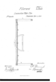
In the accompanying sheets of drawing- Figure 1, sheet 1, represents an inside view of the tank-house, showing the water-pipe' and the doors by which the pipe is enclosed.
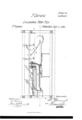
Figure 2, sheet 2, is a vertical longitudinal section .0f 1, through the line ai x.- Y
Similar letters of reference indicate corresponding parts.
A represents the tank-house.
B is the tank-tub floor. p C is the water-pipe, which is made in two parts, D and E.
The upper part, D, is soi'construeted that itconnects with the old style of valve-seat at the bottom of the tank, forming allanged joint, as seen at F, which allows the cast. pipe E to freely swing in and ont of the house, through the doorways G H.
I is a horizontal semicireular plate, in the form of `the letter D.
The centre of the bar J forms 'a pivot-support for the centre of the vertical portion of the pipe, and the seuiicircular portion forms a-traek for the support of the pipe, when the latter is swung out for use. l
K is a fxiction-roll attached to the bottom of the pipe E, which traverses the semicircle-when the pipe is passed out through the doorways G H.
L L are braces for supporting the plate I.
M M are the doors, which are suspended from chains N, and from the .weighted levers (Il by hinges. P represents the fnlernm of the levers. The arrangement is such, that when one of the levers 0 of each door'is thrown toward lthe centre, the doors (or either of them) will be thrown longitudinally Vin an opposite direction and raised by the chain N, so thatI the pipe will readily s wing in or out.
The connections R act as hinges, on which the doors turn np when drawn upon by the chain N, one end of the chain being rigidly fixed to the side of" the house, as seen at S S, and the other to the doors, as seen at 'l' T. The pipe, thus arranged, moves perfectly easy, and no water can remain therein or be wasted, as the water has a free passage, and the joint works perfect- `ly tight.
The doors M are so arranged that the pipe can swing in or, out in either direction. They close by their own gravity, but the levers O O' are operated from the outside by means of the cords u u, which pass through the side of the tank-house.
By this arrangement, thel great damage and loss, occasioned by the freezing of` the wate'rpipes at watering-stations in cold weather, are avoided, as the pipe can be kept withinthe tank-house, except when it is in actual use.
The advantages of this arrangement in other respects are many, and must be obvious toall who are acquainted with the subject.
Having thus described my invention,
lVhat I claim as new, and desire to secure by Letters Patent, is-
1. The combination of the water-pipe, swivel-jointed at F, and having friction-roll K thereon, with the horizontal semieircularu plate I, all arranged in the manner specified. l
2. The combination of swinging doors M M, chains N, and pivoted and weighted levers O O', all arranged and operating as described.
3. The swivel-pipe joint-F, formed in three parts, and coupled together as shown.
FRANK GERRARD.
Witnesses:
EDWARD A. PHILLIPS, H. O. BREWER.
Publications (1)
| Publication Number | Publication Date |
|---|---|
| US98685A true US98685A (en) | 1870-01-11 |
Family
ID=2168145
Family Applications (1)
| Application Number | Title | Priority Date | Filing Date |
|---|---|---|---|
| US98685D Expired - Lifetime US98685A (en) | Improvement in water-supply fifes for locomotives |
Country Status (1)
| Country | Link |
|---|---|
| US (1) | US98685A (en) |
-
0
- US US98685D patent/US98685A/en not_active Expired - Lifetime
Similar Documents
| Publication | Publication Date | Title |
|---|---|---|
| US98685A (en) | Improvement in water-supply fifes for locomotives | |
| US649150A (en) | Weather-strip. | |
| US320255A (en) | jaokman | |
| US613568A (en) | Safety-gate for bridges | |
| US637403A (en) | Steel-car construction. | |
| US1190671A (en) | Power-operating device for window-sashes. | |
| US101194A (en) | Improvement in sliding doors | |
| US106771A (en) | Improvement in fire-proof railway-cars | |
| US71026A (en) | David p | |
| US1065164A (en) | Door-hanger. | |
| US1223954A (en) | Mounting for sliding doors. | |
| US322876A (en) | Measuring-spigot | |
| US120484A (en) | Improvement in gates | |
| US84222A (en) | Frederick shickle | |
| US749444A (en) | Gate-fastener. | |
| US88055A (en) | mcmanus | |
| US339579A (en) | George p | |
| US1070517A (en) | Gate for locomotive-tenders. | |
| US101765A (en) | Improvement in gates | |
| US742355A (en) | Door. | |
| US1189018A (en) | Automatic air-coupling. | |
| US378388A (en) | dosch | |
| US645587A (en) | Dumping-car. | |
| US101311A (en) | Improvement in railway-gates | |
| US870417A (en) | Car-door. |