US9866752B2 - Systems and methods for producing a combined view from fisheye cameras - Google Patents
Systems and methods for producing a combined view from fisheye cameras Download PDFInfo
- Publication number
- US9866752B2 US9866752B2 US14/954,357 US201514954357A US9866752B2 US 9866752 B2 US9866752 B2 US 9866752B2 US 201514954357 A US201514954357 A US 201514954357A US 9866752 B2 US9866752 B2 US 9866752B2
- Authority
- US
- United States
- Prior art keywords
- images
- shape
- fisheye
- cameras
- common
- Prior art date
- Legal status (The legal status is an assumption and is not a legal conclusion. Google has not performed a legal analysis and makes no representation as to the accuracy of the status listed.)
- Active, expires
Links
Images


Classifications
-
- H—ELECTRICITY
- H04—ELECTRIC COMMUNICATION TECHNIQUE
- H04N—PICTORIAL COMMUNICATION, e.g. TELEVISION
- H04N23/00—Cameras or camera modules comprising electronic image sensors; Control thereof
- H04N23/60—Control of cameras or camera modules
- H04N23/698—Control of cameras or camera modules for achieving an enlarged field of view, e.g. panoramic image capture
-
- H04N5/23238—
-
- B—PERFORMING OPERATIONS; TRANSPORTING
- B60—VEHICLES IN GENERAL
- B60R—VEHICLES, VEHICLE FITTINGS, OR VEHICLE PARTS, NOT OTHERWISE PROVIDED FOR
- B60R1/00—Optical viewing arrangements; Real-time viewing arrangements for drivers or passengers using optical image capturing systems, e.g. cameras or video systems specially adapted for use in or on vehicles
-
- B—PERFORMING OPERATIONS; TRANSPORTING
- B60—VEHICLES IN GENERAL
- B60R—VEHICLES, VEHICLE FITTINGS, OR VEHICLE PARTS, NOT OTHERWISE PROVIDED FOR
- B60R1/00—Optical viewing arrangements; Real-time viewing arrangements for drivers or passengers using optical image capturing systems, e.g. cameras or video systems specially adapted for use in or on vehicles
- B60R1/20—Real-time viewing arrangements for drivers or passengers using optical image capturing systems, e.g. cameras or video systems specially adapted for use in or on vehicles
- B60R1/22—Real-time viewing arrangements for drivers or passengers using optical image capturing systems, e.g. cameras or video systems specially adapted for use in or on vehicles for viewing an area outside the vehicle, e.g. the exterior of the vehicle
- B60R1/23—Real-time viewing arrangements for drivers or passengers using optical image capturing systems, e.g. cameras or video systems specially adapted for use in or on vehicles for viewing an area outside the vehicle, e.g. the exterior of the vehicle with a predetermined field of view
- B60R1/27—Real-time viewing arrangements for drivers or passengers using optical image capturing systems, e.g. cameras or video systems specially adapted for use in or on vehicles for viewing an area outside the vehicle, e.g. the exterior of the vehicle with a predetermined field of view providing all-round vision, e.g. using omnidirectional cameras
-
- G—PHYSICS
- G06—COMPUTING OR CALCULATING; COUNTING
- G06T—IMAGE DATA PROCESSING OR GENERATION, IN GENERAL
- G06T15/00—Three-dimensional [3D] image rendering
- G06T15/10—Geometric effects
- G06T15/20—Perspective computation
- G06T15/205—Image-based rendering
-
- G06T3/0062—
-
- G—PHYSICS
- G06—COMPUTING OR CALCULATING; COUNTING
- G06T—IMAGE DATA PROCESSING OR GENERATION, IN GENERAL
- G06T3/00—Geometric image transformations in the plane of the image
- G06T3/12—Panospheric to cylindrical image transformations
-
- H04N13/0239—
-
- H—ELECTRICITY
- H04—ELECTRIC COMMUNICATION TECHNIQUE
- H04N—PICTORIAL COMMUNICATION, e.g. TELEVISION
- H04N13/00—Stereoscopic video systems; Multi-view video systems; Details thereof
- H04N13/20—Image signal generators
- H04N13/204—Image signal generators using stereoscopic image cameras
- H04N13/239—Image signal generators using stereoscopic image cameras using two two-dimensional [2D] image sensors having a relative position equal to or related to the interocular distance
-
- H—ELECTRICITY
- H04—ELECTRIC COMMUNICATION TECHNIQUE
- H04N—PICTORIAL COMMUNICATION, e.g. TELEVISION
- H04N13/00—Stereoscopic video systems; Multi-view video systems; Details thereof
- H04N13/20—Image signal generators
- H04N13/204—Image signal generators using stereoscopic image cameras
- H04N13/243—Image signal generators using stereoscopic image cameras using three or more two-dimensional [2D] image sensors
-
- H—ELECTRICITY
- H04—ELECTRIC COMMUNICATION TECHNIQUE
- H04N—PICTORIAL COMMUNICATION, e.g. TELEVISION
- H04N23/00—Cameras or camera modules comprising electronic image sensors; Control thereof
- H04N23/60—Control of cameras or camera modules
- H04N23/68—Control of cameras or camera modules for stable pick-up of the scene, e.g. compensating for camera body vibrations
- H04N23/681—Motion detection
- H04N23/6815—Motion detection by distinguishing pan or tilt from motion
-
- H04N5/23261—
-
- H—ELECTRICITY
- H04—ELECTRIC COMMUNICATION TECHNIQUE
- H04N—PICTORIAL COMMUNICATION, e.g. TELEVISION
- H04N5/00—Details of television systems
- H04N5/222—Studio circuitry; Studio devices; Studio equipment
- H04N5/262—Studio circuits, e.g. for mixing, switching-over, change of character of image, other special effects ; Cameras specially adapted for the electronic generation of special effects
- H04N5/265—Mixing
-
- B—PERFORMING OPERATIONS; TRANSPORTING
- B60—VEHICLES IN GENERAL
- B60R—VEHICLES, VEHICLE FITTINGS, OR VEHICLE PARTS, NOT OTHERWISE PROVIDED FOR
- B60R2300/00—Details of viewing arrangements using cameras and displays, specially adapted for use in a vehicle
- B60R2300/10—Details of viewing arrangements using cameras and displays, specially adapted for use in a vehicle characterised by the type of camera system used
- B60R2300/105—Details of viewing arrangements using cameras and displays, specially adapted for use in a vehicle characterised by the type of camera system used using multiple cameras
-
- B—PERFORMING OPERATIONS; TRANSPORTING
- B60—VEHICLES IN GENERAL
- B60R—VEHICLES, VEHICLE FITTINGS, OR VEHICLE PARTS, NOT OTHERWISE PROVIDED FOR
- B60R2300/00—Details of viewing arrangements using cameras and displays, specially adapted for use in a vehicle
- B60R2300/30—Details of viewing arrangements using cameras and displays, specially adapted for use in a vehicle characterised by the type of image processing
- B60R2300/303—Details of viewing arrangements using cameras and displays, specially adapted for use in a vehicle characterised by the type of image processing using joined images, e.g. multiple camera images
Definitions
- the present disclosure relates generally to electronic devices. More specifically, the present disclosure relates to systems and methods for producing a combined view from fisheye cameras.
- Some electronic devices e.g., cameras, video camcorders, digital cameras, cellular phones, smart phones, computers, televisions, automobiles, personal cameras, wearable cameras, virtual reality devices (e.g., headsets), augmented reality devices (e.g., headsets), mixed reality devices (e.g., headsets), action cameras, surveillance cameras, mounted cameras, connected cameras, robots, drones, smart applications, healthcare equipment, set-top boxes, etc.) capture and/or utilize images.
- a smartphone may capture and/or process still and/or video images.
- the images may be processed, displayed, stored and/or transmitted.
- the images may portray a scene including a landscape and/or objects, for example.
- images may be distorted.
- images may be portrayed in a way that distorts the landscape and/or objects in the image. Distortions may be particularly noticeable in some scenarios, such as when wide-angle lenses are employed.
- systems and methods that improve wide-angle image utilization and/or processing efficiency may be beneficial.
- the electronic device includes a processor.
- the processor is configured to obtain images from a plurality of cameras.
- the processor is also configured to project each image to a respective 3-dimensional (3D) shape for each camera.
- the processor is further configured to generate a combined view from the images.
- the processor may be configured to rotate at least one of the 3D shapes to approximately align a corresponding image to a direction.
- the processor may be configured to rotate at least one of the 3D shapes to compensate for a tilt of a corresponding camera.
- the processor may be configured to project at least a portion of each 3D shape to a common 3D shape enclosing all 3D shapes associated with the cameras.
- the processor may be configured to project at least a portion of the common 3D shape to a common plane.
- the processor may be configured to project the common 3D shape from a north pole of the common 3D shape to the common plane.
- the common plane may be approximately parallel to ground.
- the processor may be configured to align the images projected to the common plane.
- the processor may be configured to determine whether an alignment error exceeds a predetermined threshold.
- the processor may be configured to determine at least one seam between adjacent images and trim the images to produce a combined image.
- the processor may be configured to project the combined image to a shape.
- the cameras may be installed in a vehicle.
- the processor may be configured to present the combined view in the vehicle.
- the images may be wide-angle images and the cameras may be wide-angle cameras.
- a method is also described.
- the method includes obtaining images from a plurality of cameras.
- the method also includes projecting each image to a respective 3-dimensional (3D) shape for each camera.
- the method additionally includes generating a combined view from the images.
- a computer-program product includes a non-transitory tangible computer-readable medium with instructions.
- the instructions include code for causing an electronic device to obtain images from a plurality of cameras.
- the instructions also include code for causing the electronic device to project each image to a respective 3-dimensional (3D) shape for each camera.
- the instructions further include code for causing the electronic device to generate a combined view from the images.
- the apparatus includes means for obtaining images from a plurality of cameras.
- the apparatus also includes means for projecting each image to a respective 3-dimensional (3D) shape for each camera.
- the apparatus further includes means for generating a combined view from the images.
- FIG. 1 illustrates an example of fisheye images captured by four fisheye cameras
- FIG. 2 illustrates one example of a combined view generated from the fisheye images in FIG. 1 ;
- FIG. 3 is a block diagram illustrating one example of an electronic device in which systems and methods for producing a combined view may be implemented;
- FIG. 4 is a flow diagram illustrating one configuration of a method for producing a combined view
- FIG. 5 shows an example of a tilt angle of a camera
- FIG. 6 is an example of fisheye images that illustrates some of the difficulties in combining multiple fisheye images from fisheye cameras with different locations;
- FIG. 7 illustrates one example of projecting a fisheye image to a three-dimensional (3D) shape
- FIG. 8 is a diagram illustrating one example of a common 3D shape in accordance with the systems and methods disclosed herein;
- FIG. 9 is a diagram illustrating an example of projecting 3D shapes onto a common 3D shape
- FIG. 10 is a diagram illustrating a more specific example of a projection of 3D shapes onto a common 3D shape
- FIG. 11 is a diagram illustrating another more specific example of a projection of 3D shapes onto a common 3D shape
- FIG. 12 is a diagram illustrating an example of a common 3D shape being projected to a common plane
- FIG. 13 is a flow diagram illustrating a more specific configuration of a method for producing a combined view
- FIG. 14 illustrates an example of four input fisheye images from four fisheye cameras
- FIG. 15 illustrates an example of a fisheye image on a plane
- FIG. 16 illustrates another example of a fisheye image on a plane
- FIG. 17 illustrates another example of a fisheye image on a plane
- FIG. 18 illustrates an example of fisheye images on a common plane
- FIG. 19 illustrates another example of fisheye images on a common plane
- FIG. 20 illustrates an example of a combined view on a common plane
- FIG. 21 illustrates another example of a combined view
- FIG. 22 illustrates another example of a combined view
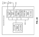
- FIG. 23 illustrates certain components that may be included within an electronic device configured to implement various configurations of the systems and methods disclosed herein.
- Some configurations of the systems and methods disclosed herein may provide combined view (e.g., surround view) generation from cameras.
- the systems and methods disclosed herein may be applied in conjunction with a variety of cameras, lenses and/or images.
- one or more wide-angle cameras, wide field of view (FOV) cameras, fisheye cameras, normal cameras and/or long-focus (e.g., telephoto) cameras may be utilized to provide one or more wide-angle images, wide-FOV images, fisheye images, curved images, spherical images, hemispherical images, normal images, long-focus images, etc.
- FOV wide field of view
- telephoto long-focus
- the images may be two-dimensional (2D) images with a wide-angle, wide-FOV, fisheye, curved, spherical, hemispherical, normal and/or long-focus appearance and/or properties (e.g., perspective distortion, expanded FOV, negligible or no distortion, contracted FOV, magnification, etc.).
- a wide-angle camera may include at least one wide-angle lens
- a wide-FOV camera may include at least one wide-FOV lens
- a fisheye camera may include at least one fisheye lens
- a normal camera may include at least one normal lens
- a long-focus camera may include at least one long-focus lens.
- Normal cameras and/or normal lenses may produce normal images, which do not appear distorted (or that have only negligible distortion).
- Wide-angle lenses and wide-FOV lenses e.g., wide-angle cameras, wide-FOV cameras
- Wide-angle lenses and wide-FOV lenses may have shorter focal lengths than normal lenses and/or may produce images with an expanded field of view.
- Wide-angle lenses and wide-FOV lenses e.g., wide-angle cameras, wide-FOV cameras
- wide-angle lenses and/or wide-FOV lenses may produce wide-angle images, wide-FOV images, curved images, spherical images, hemispherical images, fisheye images, etc.
- Long-focus lenses and/or long-focus cameras may have longer focal lengths than normal lenses and/or may produce images with a contracted field of view and/or that appear magnified.
- a “fisheye camera” may an example of a wide-angle and/or wide field-of-view (FOV) camera.
- a fisheye camera may produce images with an angle of view between approximately 100 and 180 degrees.
- many fisheye lenses may have a FOV larger than 100 degrees.
- Some fisheye lenses have an FOV of at least 140 degrees.
- some fisheye lenses used in the advanced driver assistance system (ADAS) context may have FOVs of 140 degrees or greater.
- a fisheye lens has an FOV of 185 degrees.
- Fisheye lenses may produce images that are panoramic and/or approximately spherical (e.g., hemispherical) in appearance.
- Fisheye cameras may generate images with large distortions. For instance, some horizontal lines in a scene captured by a fisheye camera may appear to be curved rather than straight. Accordingly, fisheye lenses may exhibit distortion and/or large FOVs in comparison with other lenses (e.g., regular cameras).
- systems and methods disclosed herein may be described in terms of fisheye lenses, fisheye cameras and/or fisheye images. It should be noted that the systems and methods disclosed herein may be additionally or alternatively applied in conjunction with one or more normal lenses, wide-angle lenses, wide-FOV lenses, long-focus lenses, normal cameras, wide-angle cameras, wide-FOV cameras, long-focus cameras, normal images, wide-angle images, wide-FOV images and/or long-focus images, etc.
- examples that refer to one or more “fisheye cameras,” “fisheye lenses” and/or “fisheye images” may additionally or alternatively disclose other corresponding examples with normal lenses, wide-angle lenses, wide-FOV lenses, long-focus lenses, normal cameras, wide-angle cameras, wide-FOV cameras, long-focus cameras, normal images, wide-angle images, wide-FOV images and/or long-focus images, etc., instead of fisheye cameras, fisheye lenses and/or fisheye images.
- General references to one or more “cameras” may refer to any or all of normal cameras, wide-angle cameras, wide-FOV cameras, fisheye cameras and/or long-focus cameras, etc.
- General references to one or more “lenses” or “optical systems” may refer to any or all of normal lenses, wide-angle lenses, wide-FOV lenses, fisheye lenses and/or long-focus lenses, etc.
- General references to one or more “images” may refer to any or all of normal images, wide-angle images, wide-FOV images, fisheye images and/or long-focus images.
- the systems and methods disclosed herein may be applied in many contexts, devices and/or systems.
- the systems and methods disclosed herein may be implemented in electronic devices, vehicles, drones, cameras, computers, security systems, wearable devices (e.g., action cameras), airplanes, boats, recreational vehicles, virtual reality (VR) devices (e.g., VR headsets), augmented reality (AR) devices (e.g., AR headsets), etc.
- VR virtual reality
- AR augmented reality
- Fisheye cameras may be installed in multiple positions. For example, four cameras may be positioned with one camera in the front, one at the left, one at the right and one at the rear part of a vehicle. Different fisheye cameras may have different tilt angles. The fisheye images from the fisheye cameras may have overlapping regions. In some configurations, more or fewer than four cameras may be installed and used for generation of the combined view (e.g., surround view) of 360 degrees or less than 360 degrees.
- a combined view may be a combination of images that provides a larger angle of view than each individual image alone.
- a surround view may be a combined view that partially or fully surrounds an object (e.g., vehicle, drone, building, etc.).
- the combined view (e.g., surround view) generated from the wide FOV cameras may be used to generate a three-dimensional (3D) combined view (e.g., surround view).
- 3D three-dimensional
- How to connect the output images from multiple fisheye cameras to generate a combined view presents a challenging problem.
- Image stitching may be referred to as image stitching (e.g., panorama stitching).
- Surround view generation may be associated with panorama stitching problems.
- Panorama stitching may work when images are captured by a rotating camera.
- Panorama stitching may be more challenging with multiple cameras (e.g., fisheye cameras) due to image distortions and a wide baseline. The distortion may be introduced by fisheye camera(s), while the wide baseline may be caused by placing cameras at different positions. In these cases, the cameras may not be modeled as a rotating camera.
- One approach is to un-distort the fisheye images wholly or partially and then apply panorama stitching to the images.
- This approach may not allow for good stitching due to the blur (e.g., blurred overlapping regions) caused by un-distortion and the difficulties caused by a wide baseline.
- undistorted images may have blurred overlapping regions, which may be difficult to stitch successfully.
- images may be unwarped and then panorama stitching may be applied.
- images may be unwarped to remove some distortions in the vertical direction, and then the images may be stitched.
- This approach may work for some camera setups, but may fail for other camera setups. For example, it may be difficult to unwarp the images to enable successful stitching.
- generating the image may crop large parts of sky and ground regions.
- the generated image may be a strip (e.g., rectangular) image, where the first image is not connected to last image.
- Another approach may be to produce a full view sphere from a fisheye camera. This approach may only work well for rotating cameras.
- fisheye cameras may be modeled as a 3D shape (e.g., a sphere, spheroid, spherical shape, ellipsoid, polyhedron, trapezoidal prism, box, cube, rectangular prism, etc.).
- a 3D shape e.g., a sphere, spheroid, spherical shape, ellipsoid, polyhedron, trapezoidal prism, box, cube, rectangular prism, etc.
- Multiple fisheye images generated by fisheye cameras with wide baselines may be projected into separate 3D shapes.
- each fisheye camera may be modeled as a separate 3D shape (e.g., sphere) with different 3D locations and/or possibly different radii (which may be related to the focal length of the fisheye lens).
- Each of the 3D shapes may have similar tilt angles and/or may point toward each of the camera directions (e.g., forward, left, right, back, etc.).
- a common 3D shape enclosing the separate 3D shapes may be found.
- each small sphere (corresponding to a separate fisheye camera, for instance) may be enclosed by a common sphere.
- the images on the small 3D shapes can be projected to this common 3D shape.
- the small spheres can be projected to the common sphere.
- “common” in this context means that the common 3D shape is common to multiple 3D shapes.
- the multiple 3D shapes may be projected to a single common 3D shape.
- the projected image may stitch well in the common 3D shape. With a wide baseline, the image may not match well.
- a further projection from the north pole of the common sphere, for example
- these images e.g., projected images
- these images may be aligned and stitched to get large field of view (FOV) image (e.g., combined view, surround view, etc.).
- FOV field of view
- steps may be taken to transform it to a sphere or other 3D structure to get one or more 3D effects.
- the image on the common ground may be projected to a sphere to produce a 3D effect.
- Some benefits of the systems and methods disclosed herein may include handling multiple fisheye cameras with large baselines and/or different tilt angles.
- the systems and methods disclosed herein may keep almost all image content (such as sky and ground) from the original fisheye images.
- an ADAS may generate a bird's-eye view, which is a view seen from above the car to the ground around the car.
- the bird's-eye view may generally show some good results in ground views.
- other objects above ground may be highly distorted (e.g., flattened).
- Some approaches may generate full-view images from fisheye images captured by a rotating camera. Again, due to the wide baseline problem, these approaches may not work well.
- ADAS advanced driver assistance system
- multiple wide FOV cameras such as fisheye cameras
- fisheye cameras may be installed in a vehicle (e.g., different sides of a vehicle) to allow a driver to observe surrounding scenes.
- fisheye cameras may provide a view (to the driver, for instance) of objects on the ground and above ground.
- an automotive combined view (e.g., surround view) system may be an automotive ADAS technology that provides a driver of a vehicle a 360-degree view of the area surrounding the vehicle.
- Some combined view (e.g., surround view) systems may include four to six wide field-of-view (FOV) cameras, such as fisheye cameras, mounted around the vehicle.
- a combined view (e.g., surround view) generated from these cameras may assist the driver in real time (e.g., during parking).
- FIG. 1 illustrates an example of fisheye images 102 a - d captured by four fisheye cameras.
- the fisheye images 102 a - d may be input fisheye images supplied by separate fisheye cameras.
- the fisheye images 102 a - d generated by the fisheye cameras have large distortions. For example, the building in the first fisheye image 102 a appears curved.
- the fisheye cameras may be mounted on a vehicle, where the first fisheye camera is on the right side of the vehicle, the second fisheye camera is on the front of the vehicle, the third fisheye camera is on the left side of the vehicle and the fourth fisheye camera is on the rear of the vehicle.
- An ADAS system with multiple fisheye cameras installed in a vehicle has a wide baseline problem because the distances between the cameras are relatively large (e.g., the front camera is installed in the front grill of a car and side cameras are installed under the side-view mirrors). Accordingly, the cameras may not be modeled as a rotating camera.
- the same object may show different facets in different fisheye images.
- the object may not match well between fisheye images, regardless of which linear transformations are used.
- An additional problem is that the fisheye cameras installed in a vehicle may have different tilt angles.
- the front camera may be relatively tilted down, causing more ground (e.g., more content below the horizon) to be captured as illustrated in the second fisheye image 102 b .
- a side camera may be relatively tilted up, causing more content above the horizon to the captured as illustrated in the first fisheye image 102 a .
- the tilt angles may be different and may be relatively large in some cases.
- the overlapping region(s) between fisheye images may be relatively small. Additionally or alternatively, fisheye images may lack features (e.g., may have large regions of texture-less sky and/or ground) in some cases. Accordingly, combining the fisheye images may be difficult.
- FIG. 2 illustrates one example of a combined view 204 (e.g., 360-degree surround view) generated from the fisheye images 102 a - d in FIG. 1 .
- a view of the surroundings may be generated with multiple fisheye images in accordance with the systems and methods disclosed herein.
- FIG. 3 is a block diagram illustrating one example of an electronic device 310 in which systems and methods for producing a combined view may be implemented.
- the electronic device 310 may be configured to generate a combined view (e.g., surround view) from fisheye cameras.
- a combined view e.g., surround view
- Examples of the electronic device 310 include cameras, video camcorders, digital cameras, cellular phones, smart phones, computers (e.g., desktop computers, laptop computers, etc.), tablet devices, media players, televisions, vehicles, automobiles, personal cameras, wearable cameras, virtual reality devices (e.g., headsets), augmented reality devices (e.g., headsets), mixed reality devices (e.g., headsets), action cameras, surveillance cameras, mounted cameras, connected cameras, robots, aircraft, drones, unmanned aerial vehicles (UAVs), smart applications, healthcare equipment, gaming consoles, personal digital assistants (PDAs), set-top boxes, appliances, etc.
- the electronic device 310 may include one or more components or elements. One or more of the components or elements may be implemented in hardware (e.g., circuitry) or a combination of hardware and software (e.g., a processor with instructions).
- the electronic device 310 may include a processor 314 , a memory 308 , a display 306 , one or more image sensors 312 , one or more optical systems 326 , and/or a communication interface 322 .
- the processor 314 may be coupled to (e.g., in electronic communication with) the memory 308 , display 306 , image sensor(s) 312 , optical system(s) 326 , and/or communication interface 322 .
- the processor 314 may be a general-purpose single- or multi-chip microprocessor (e.g., an ARM), a special-purpose microprocessor (e.g., a digital signal processor (DSP)), a microcontroller, a programmable gate array, etc.
- DSP digital signal processor
- the processor 314 may be referred to as a central processing unit (CPU). Although just a single processor 314 is shown in the electronic device 310 , in an alternative configuration, a combination of processors (e.g., an ARM and a DSP) could be used.
- the processor 314 may be configured to implement the methods disclosed herein, which will be explained in detail below, to produce the combined view (e.g., surround view) from the images (e.g., wide-angle images, fisheye images, etc.).
- the electronic device 310 may perform one or more of the functions, procedures, methods, steps, etc., described in connection with one or more of FIGS. 4 and 7-22 .
- the communication interface 322 may enable the electronic device 310 to communicate with one or more other electronic devices.
- the communication interface 322 may provide an interface for wired and/or wireless communications.
- the communication interface 322 may be coupled to one or more antennas 324 for transmitting and/or receiving radio frequency (RF) signals.
- RF radio frequency
- the communication interface 322 may enable one or more kinds of wireline (e.g., Universal Serial Bus (USB), Ethernet, etc.) communication.
- multiple communication interfaces 322 may be implemented and/or utilized.
- one communication interface 322 may be a cellular (e.g., 3G, Long Term Evolution (LTE), CDMA, etc.) communication interface 322
- another communication interface 322 may be an Ethernet interface
- another communication interface 322 may be a universal serial bus (USB) interface
- yet another communication interface 322 may be a wireless local area network (WLAN) interface (e.g., Institute of Electrical and Electronics Engineers (IEEE) 802.11 interface).
- WLAN wireless local area network
- the communication interface 322 may send information (e.g., image information, combined view information, etc.) to and/or receive information from another device (e.g., a vehicle, a smart phone, a camera, a display, a remote server, etc.).
- another device e.g., a vehicle, a smart phone, a camera, a display, a remote server, etc.
- the electronic device 310 may share information with a vehicle (e.g., another vehicle).
- the electronic device 310 may obtain one or more images (e.g., digital images, image frames, video, etc.).
- the electronic device 310 may include the image sensor(s) 312 and the optical system(s) 326 (e.g., lenses) that focus images of scene(s) and/or object(s) that are located within the field of view of the optical system 326 onto the image sensor 312 .
- a camera e.g., a visual spectrum camera
- the electronic device 310 may be one or more cameras and/or may include one or more cameras in some implementations.
- the image sensor(s) 312 may capture the one or more images.
- the optical system(s) 326 may be coupled to and/or controlled by the processor 314 . Additionally or alternatively, the electronic device 310 may request and/or receive the one or more images from another device (e.g., one or more external cameras coupled to the electronic device 310 , a network server, traffic camera(s), drop camera(s), vehicle camera(s), web camera(s), etc.). In some configurations, the electronic device 310 may request and/or receive the one or more images via the communication interface 322 . For example, the electronic device 310 may or may not include camera(s) (e.g., image sensor(s) 312 and/or optical system(s) 326 ) and may receive images from one or more remote device(s). One or more of the images (e.g., image frames) may include one or more scene(s) and/or one or more object(s).
- another device e.g., one or more external cameras coupled to the electronic device 310 , a network server, traffic camera(s), drop camera(s), vehicle camera
- the optical system(s) 326 may include one or more lenses (e.g., wide-angle lenses, wide-FOV lenses, fisheye lenses, etc.). Accordingly, the optical system(s) 326 and image sensor(s) 312 may be components of one or more cameras (e.g., wide-angle cameras, wide-FOV cameras, fisheye cameras, etc.) that are included in the electronic device 310 . Additionally or alternatively, the electronic device 310 may be coupled to and/or communicate with one or more external cameras (e.g., external wide-angle cameras, external wide-FOV cameras, external fisheye cameras, etc.).
- external cameras e.g., external wide-angle cameras, external wide-FOV cameras, external fisheye cameras, etc.
- the electronic device 310 may include an image data buffer (not shown).
- the image data buffer may buffer (e.g., store) image data from the image sensor(s) 312 and/or external camera(s).
- the buffered image data may be provided to the processor 314 .
- the electronic device 310 may include a camera software application and/or a display 306 .
- the camera application When the camera application is running, images of objects that are located within the field of view of the optical system(s) 326 may be captured by the image sensor(s) 312 .
- the images that are being captured by the image sensor(s) 312 may be presented on the display 306 .
- one or more combined view (e.g., surround view) images may be sent to the display 306 for viewing by a user.
- these images may be displayed in rapid succession at a relatively high frame rate so that, at any given moment in time, the scene(s) and/or object(s) that are located within the field of view of the optical system(s) 326 are presented on the display 306 .
- the one or more images obtained by the electronic device 310 may be one or more video frames and/or one or more still images.
- the display 306 may present additional or alternative information.
- the display 306 may present one or more regions of interest (e.g., bounding boxes) corresponding to one or more detected and/or tracked objects.
- the display 306 may present depth information (e.g., one or more estimated distances to one or more objects (e.g., selected objects) in a combined view).
- the processor 314 may include and/or implement an image obtainer 316 .
- One or more of the image frames may be provided to the image obtainer 316 .
- the image obtainer 316 may obtain images (e.g., curved images, wide-angle images, wide-FOV images, fisheye images, etc.) from one or more cameras (e.g., wide-angle cameras, wide-FOV cameras, fisheye cameras, etc.).
- the image obtainer 316 may receive image data from one or more image sensors 312 and/or from one or more external cameras.
- the images may be captured from a single camera (e.g., one camera at multiple positions (e.g., angles, locations, etc.)) or may be captured from multiple cameras (at different locations, for example).
- the image(s) may be captured from the image sensor(s) 312 (e.g., wide-angle cameras, wide-FOV cameras, fisheye cameras, etc.) included in the electronic device 310 or may be captured from one or more remote camera(s) (e.g., remote wide-angle cameras, remote wide-FOV cameras, remote fisheye cameras, etc.).
- the image sensor(s) 312 e.g., wide-angle cameras, wide-FOV cameras, fisheye cameras, etc.
- remote camera(s) e.g., remote wide-angle cameras, remote wide-FOV cameras, remote fisheye cameras, etc.
- the image obtainer 316 may request and/or receive one or more images (e.g., wide-angle images, wide-FOV images, fisheye images, curved images, spherical images, hemispherical images, etc.).
- the image obtainer 316 may request and/or receive one or more images from a remote device (e.g., external camera(s), remote server, remote electronic device, etc.) via the communication interface 322 .
- the images obtained from the cameras may be processed by the processor 314 to produce a combined view (e.g., surround view).
- the processor 314 may include and/or implement an image operator 318 .
- the image operator 318 may perform one or more operations on the images (e.g., fisheye images). Examples of operations that may be performed on the images may include projecting each image (e.g., wide-angle image, wide-FOV image, fisheye image, curved image, spherical image, hemispherical image, etc.) to a 3D shape, rotating one or more 3D shapes (to align 3D shape and/or image to a particular direction), projecting at least a portion of each 3D shape to a common 3D shape enclosing all 3D shapes associated with the cameras and/or projecting at least a portion of the common 3D shape to a common plane.
- each image e.g., wide-angle image, wide-FOV image, fisheye image, curved image, spherical image, hemispherical image, etc.
- 3D shape rotating one or more 3D shapes (to align 3D shape and/or image
- the image operator 318 may project each of the images (e.g., wide-angle images, wide-FOV images, fisheye images, curved images, spherical images, hemispherical images, etc.) to a respective 3D shape.
- the image operator 318 may project each of the images to a respective sphere, spheroid, spherical shape, curved 3D shape, hemisphere, ellipsoid, polyhedron (e.g., polyhedron that approximates a sphere or other polyhedron), trapezoidal prism, box, cube, rectangular prism, etc.
- each camera may produce an image that may be projected to a separate 3D shape.
- each image may be projected to a sphere. Projecting each image to a 3D shape (e.g., sphere, spheroid, ellipsoid, etc.) may make combining the images easier and/or may reduce final errors.
- An image may be projected to all or to a portion of the corresponding 3D shape in some approaches. For example, an image may be projected only to approximately half of a sphere (e.g., ⁇ 90 degrees to 90 degrees in a horizontal direction and ⁇ 70 degrees to 70 degrees in a vertical direction).
- the image operator 318 may rotate at least one of the 3D shapes to approximately align a corresponding image to a direction.
- each of the 3D shapes e.g., the images projected to the 3D shapes
- one or more of the 3D shapes may be rotated to point to one or more respective directions.
- This rotation may be a horizontal rotation (e.g., a rotation around a vertical axis).
- the direction for each 3D shape (e.g., image) may be the direction of the corresponding camera.
- a first sphere e.g., the first image projected on the first sphere
- a second sphere e.g., the second image projected on the second sphere
- a third sphere e.g., the third image projected on the third sphere
- a fourth sphere e.g., the fourth image projected on the fourth sphere
- only a subset of the 3D shapes may be rotated. For example, one of four spheres may already be pointed in the correct direction when the image is projected. Accordingly, only three of the four spheres may be rotated.
- one or more 3D shapes may be rotated to an approximate direction (e.g., 90 degrees, 180 degrees, 270 degrees, etc.).
- the rotation angle in degrees and/or radians, for example
- a forward direction may be a 90 degree rotation in an ideal case.
- the rotation angle vary (e.g., 92 degrees, 88 degrees, etc.).
- the image operator 318 may rotate at least one of the 3D shapes to approximately compensate for a tilt of a corresponding camera.
- the image operator 318 may rotate one or more of the 3D shapes (e.g., spheres) such that the tilt is matched between the cameras. This rotation may be a vertical rotation (e.g., a rotation around a horizontal axis).
- the image operator 318 may tilt one or more of the 3D shapes such that the tilt of all of the 3D shapes is a specific tilt (e.g., 10 degrees, 5 degrees, 0 degrees, ⁇ 5 degrees, ⁇ 10 degrees, etc.).
- the tilt may be predetermined, user configured and/or automatically detected.
- the tilt of one camera may be determined (e.g., calibrated, automatically detected and/or user configured).
- the image operator 318 may rotate the corresponding 3D shapes of the other cameras such that they match the tilt of the determined camera.
- the image operator 318 may project at least a portion of each 3D shape to a common 3D shape.
- the common 3D shape may enclose (e.g., contain) all of the 3D shapes that correspond to the cameras.
- all of the 3D shapes that correspond to the cameras may be located in the interior of the common 3D shape.
- all points of a 3D shape that is enclosed by the enclosing (e.g., common) 3D shape may be within the enclosing 3D shape and/or may intersect with the enclosing 3D shape. All of the 3D shapes may be enclosed within the common 3D shape in order to facilitate projection of the 3D shapes to the common 3D shape.
- FIG. 8 illustrates an example of a common sphere enclosing multiple spheres.
- the image operator 318 may project at least a portion of each 3D shape to the common 3D shape.
- FIG. 9 illustrates an example of spheres being projected to a common sphere.
- the portion of the 3D shape that may be projected may include less than, exactly, or more than a section of the 3D shape that includes the image projected to the 3D shape.
- This portion of the 3D shape may be projected to a portion of the common 3D shape.
- multiple images may be projected from the 3D shapes to multiple portions of the common 3D shape.
- the multiple portions of the common 3D shape may overlap.
- the multiple images projected to the common 3D shape (from their respective 3D shapes) may overlap.
- the multiple images projected to the common 3D shape (from their respective 3D shapes) may not overlap.
- One or more projection origination points may be utilized.
- one or more interior points and/or one or more exterior points relative to the common 3D shape may be utilized as projection origination points.
- a center of a common sphere may be utilized as a projection origination point for the projection of each of a number of spheres (corresponding to each camera, for example) to the common sphere.
- FIG. 10 illustrates an example of a sphere center as a projection origination point.
- the centers of each of a number of spheres (corresponding to each camera, for example) may be utilized as projection origination points for each respective sphere.
- FIG. 11 illustrates an example of centers of spheres as projection origination points.
- the image operator 318 may project at least a portion of the common 3D shape to a common plane.
- the portion of the common 3D shape that may be projected may include less than, exactly, or more than a section of the common 3D shape that includes the images projected to the common 3D shape.
- This portion of the common 3D shape may be projected to a portion of the common plane. Accordingly, multiple images may be projected from the common 3D shape to a portion of the common plane.
- a projection origination point may be exterior to, upon, or interior to the common 3D shape.
- the projection origination point may be at a top central point of the common 3D shape.
- FIG. 12 illustrates an example of the common 3D shape being projected to a common plane, where the projection origination point is a north pole of a sphere.
- the common plane may be approximately parallel to the ground.
- the processor 314 may include and/or implement a combined view generator 320 .
- the combined view generator 320 may generate a combined view based on the images.
- the combined view generator 320 may combine the images (that have been projected to the common plane, for instance) to form the combined image.
- the combined view generator 320 may perform image alignment (e.g., registration), seam finding and/or trimming (e.g., cropping) to produce a combined image.
- Image alignment may include aligning the images in order to approximately match overlapping areas (e.g., regions) of the images (in the common plane, for instance). For example, all or portions of the overlapping areas may be approximately matched to align the images.
- the images may be translated and/or scaled in order to approximately match the overlapping areas. For example, an affine transform may be applied to align the images. Additionally or alternatively, a projective transform and/or image morphing may be utilized to align the images.
- one or more of the foregoing procedures may be repeated and/or skipped until an alignment error is less than an alignment error threshold.
- FIG. 13 illustrates an example of image alignment where one or more of these procedures may be repeated and/or skipped based on an alignment error.
- Seam finding may include determining a seam between adjacent images (e.g., in overlapping areas between images).
- the seam may be generated in order to improve continuity (e.g., reduce discontinuity) between the images.
- the combined view generator 320 may determine a seam along which the images match well and/or where differences are small (e.g., where edges, objects, textures, color and/or intensity match well).
- Trimming the images may include trimming (e.g., cropping) portions of the overlapping areas. For each image, for example, image data on one side of the seam may be kept, while image data on the other side of the seam may be trimmed (e.g., cropped, discarded, etc.).
- the resulting combined image on the common plane may be the combined view in some configurations.
- the combined view generator 320 may project the combined image to a shape.
- the combined image (on the common plane, for instance) may be projected to shape such as a bowl (e.g., bowl interior), a cup (e.g., cup interior), a sphere (e.g., whole sphere interior, partial sphere interior, half-sphere interior, etc.), a spheroid (e.g., whole spheroid interior, partial spheroid interior, half-spheroid interior, etc.), a cylinder (e.g., whole cylinder interior, partial cylinder interior, etc.), an ellipsoid (e.g., whole ellipsoid interior, partial ellipsoid interior, half-ellipsoid interior, etc.), polyhedron (e.g., polyhedron interior, partial polyhedron interior, etc.), trapezoidal prism (e.g., trapezoidal prism interior, partial trapezoidal prism interior, etc.
- a “bowl” (e.g., multilayer bowl) shape may be a (whole or partial) sphere, spheroid, or ellipsoid with a flat (e.g., planar) base. The shape may or may not be symmetrical.
- the electronic device 310 e.g., combined view generator 320
- the model or representation may be predetermined in some configurations.
- the resulting combined image projected to the shape may be the combined view.
- the combined view generator 320 may render the combined view (on the common plane and/or on the shape).
- the rendered combined view may be presented on the display 306 .
- the processor 314 may provide the combined view to the display 306 , which may present the combined view.
- the combined view may be presented from a viewpoint (e.g., perspective, camera angle, etc.).
- a viewpoint e.g., perspective, camera angle, etc.
- the combined view may be presented from a top-down viewpoint, a back-to-front viewpoint (e.g., raised back-to-front, lowered back-to-front, etc.), a front-to-back viewpoint (e.g., raised front-to-back, lowered front-to-back, etc.), an oblique viewpoint (e.g., hovering behind and slightly above, other angled viewpoints, etc.), etc.
- a back-to-front viewpoint e.g., raised back-to-front, lowered back-to-front, etc.
- a front-to-back viewpoint e.g., raised front-to-back, lowered front-to-back, etc.
- an oblique viewpoint e.g., hovering behind and slightly above, other angled viewpoints, etc.
- Some configurations of the systems and methods disclosed herein may also provide free view rendering, where the combined view may be rendered from any viewpoint (e.g., any rendering angle) or given ranges of viewpoints.
- the combined view may be adjusted based on user interface 328 input.
- the user interface 328 e.g., a touchscreen
- the user interface 328 may receive an input that indicates a rotation, shift, and/or zoom of the combined view.
- the combined view generator 320 may change the rotation of the combined view based on a swipe, which may indicate a rotation in the swipe direction, may change the shift of the combined view based on a multi-touch swipe (e.g., two-finger swipe), may indicate a shift in the swipe direction, and/or may change the zoom of the combined view based on a multi-touch pinch or spread.
- a swipe which may indicate a rotation in the swipe direction
- a multi-touch swipe e.g., two-finger swipe
- the electronic device 310 may identify a region of interest (ROI) in the one or more images (e.g., combined image). For example, the electronic device 310 may perform object detection based on the one or more images and. For instance, the electronic device 310 may detect objects such as signs, road signs, traffic signs, traffic signals, people, faces, symbols (e.g., characters, text, numbers, etc.), vehicles, buildings, obstructions, etc. The electronic device 310 may identify the ROI based on the detected object. For example, the ROI may be a region that is established relative to the detected object. In some configurations, the electronic device 310 may bound the detected object with a bounding box. The ROI may be region included within the bounding box.
- ROI region of interest
- the electronic device 310 may zoom at least a portion of the combined view based on the ROI.
- the electronic device 310 e.g., combined view generator 320
- the electronic device 310 e.g., combined view generator 320
- the electronic device 310 e.g., processor 314 and/or display 306
- the memory 308 may store instructions and/or data.
- the processor 314 may access (e.g., read from and/or write to) the memory 308 .
- Examples of instructions and/or data that may be stored by the memory 308 may include image data, image combining data (e.g., seam location data), combined view data (e.g., geometry data, geometry parameters, geometry viewpoint data, geometry shift data, geometry rotation data, etc.), object data (e.g., location, size, shape, etc.), image obtainer 316 instructions, image operator 318 instructions, and/or combined view generator 320 instructions, etc.
- the memory 308 may store the images and instruction codes for performing operations by the processor 314 .
- the memory 308 may be any electronic component capable of storing electronic information.
- the memory 308 may be embodied as random access memory (RAM), read-only memory (ROM), magnetic disk storage media, optical storage media, flash memory devices in RAM, on-board memory included with the processor, EPROM memory, EEPROM memory, registers, and so forth, including combinations thereof.
- Data and instructions may be stored in the memory 308 .
- the instructions may be executable by the processor 314 to implement one or more of the methods described herein. Executing the instructions may involve the use of the data that is stored in the memory 308 .
- various portions of the instructions may be loaded onto the processor 314 , and various pieces of data may be loaded onto the processor.
- the electronic device 310 may present a user interface 328 on the display 306 .
- the user interface 328 may enable a user to interact with the electronic device 310 .
- the user interface 328 may enable a user to indicate preferences (e.g., combined view settings) and/or interact with the combined view.
- the user interface 328 may receive one or more commands for changing the combined view (e.g., zooming in or out, rotating the combined view, shifting the combined view, changing combined view shape, changing the combined view viewpoint, etc.).
- the user interface 328 may receive an input (e.g., a tap) that indicates a selection of an object in the combined view. In some configurations, the selected object may be tracked.
- one or more the parameters used in the algorithm may be adjusted based on an input (e.g., manually). Additionally or alternatively, one or more parameters may be adapted for optimization problems, which may be solved by minimizing some defined energy functions, for example.
- the display 306 may be a touchscreen that receives input from physical touch (by a finger, stylus or other tool, for example).
- the touchscreen may be an input interface that receives touch input indicating user preference(s) and/or one or more modifications the image visualization.
- the electronic device 310 may include or be coupled to another input interface.
- the electronic device 310 may include a camera facing a user and may detect user gestures (e.g., hand gestures, arm gestures, eye tracking, eyelid blink, etc.).
- the electronic device 310 may be coupled to a mouse and may detect a mouse click indicating an input.
- the electronic device 310 may automatically produce the combined view as described herein.
- the electronic device 310 may optionally be coupled to, be part of (e.g., be integrated into), include and/or implement an advanced driving assistance system (ADAS).
- ADAS advanced driving assistance system
- the electronic device 310 may present the combined view in a vehicle (on an in-dash display, a console display, a windshield projector, a heads-up display, optical head mounted display, etc.). This may assist the driver in situational awareness and/or collision avoidance.
- the electronic device 310 may optionally be coupled to, be part of (e.g., be integrated into), include and/or implement one or more other kinds of devices.
- the electronic device 310 may be implemented in a drone equipped with cameras. The combined view may provide a wide view of the scene captured by multiple cameras on the drone.
- the electronic device 310 e.g., processor 314
- one or more of the elements or components of the electronic device may be combined and/or divided.
- the image obtainer 316 , the image operator 318 and/or the combined view generator 320 may be combined. Additionally or alternatively, one or more of the image obtainer 316 , the image operator 318 and/or the combined view generator 320 may be divided into elements or components that perform a subset of the operations thereof.
- FIG. 4 is a flow diagram illustrating one configuration of a method 400 for producing a combined view.
- the method 400 may be performed by the electronic device 310 described herein, for example.
- the electronic device 310 may obtain 402 images (e.g., wide-angle images, wide-FOV images, fisheye images, curved images, spherical images, hemispherical images, etc.) from a plurality of cameras (e.g., wide-angle cameras, wide-FOV cameras, fisheye cameras, etc.). This may be accomplished as described in connection with one or more of FIGS. 1 and 3 .
- the electronic device 310 may obtain images from a plurality of cameras included in the electronic device 310 .
- the electronic device 310 may request and/or receive the images from multiple cameras coupled to (e.g., in electronic communication with) the electronic device 310 .
- the electronic device 310 may request and/or receive the images from one or more remote devices (e.g., remote server, etc.). In some configurations, each camera may supply one image of the plurality of images (at a time, for example).
- the electronic device 310 may project 404 each image (e.g., wide-angle image, wide-FOV image, fisheye image, curved image, spherical image, hemispherical image, etc.) to a respective 3D shape for each camera. This may be accomplished as described in connection with FIG. 3 .
- the electronic device 310 may project each of the images to a separate 3D shape (e.g., sphere, ellipsoid, polyhedron, etc.).
- each of the images may be mapped to all or a portion of a 3D shape.
- each of the 3D shapes may be the same type (e.g., all spheres) or one or more of the 3D shapes may be different (e.g., three spheres and an ellipsoid, etc.).
- the electronic device 310 may generate 406 a combined view from the images (e.g., wide-angle images, wide-FOV images, fisheye images, curved images, spherical images, hemispherical images, etc.). This may be accomplished as described in connection with FIG. 3 .
- the electronic device 310 may perform image alignment, seam finding and/or trimming.
- the electronic device 310 may align the images (e.g., projections of the images on the 3D shapes, projections of the images on a common 3D shape and/or projections of the images on a common plane, etc.).
- the electronic device 310 may align at least portions of the images projected to the common plane.
- the electronic device 310 may determine whether an alignment error is small enough (e.g., less than an alignment error threshold) and/or may repeat one or more operations until the alignment error is small enough.
- the electronic device 310 may find seams between adjacent images and/or may trim a portion of each of the images.
- the electronic device 310 may display the combined view. This may be accomplished as described in connection with FIG. 3 .
- the electronic device 310 e.g., processor 314
- may provide the combined view to a display e.g., a display 306 included in the electronic device 310 or to a display that is coupled to and/or in communication with the electronic device 310 .
- the display may present the combined view.
- the cameras may be installed in a vehicle and the combined view may be presented in a vehicle.
- FIG. 5 shows an example of a tilt angle 534 of a camera 530 .
- the camera 530 e.g., fisheye camera
- the axis 532 may be an arbitrary axis (e.g., parallel to the ground, perpendicular to a gravitational vector, aligned with a horizon, an axis relative to the structure of a physical body (e.g., vehicle, drone frame, building, etc.), a pointing direction of another camera, a predetermined axis, etc.).
- the tilt angles of different cameras may be different and can be relatively large. Accordingly, different cameras (e.g., fisheye cameras) may capture a surrounding scene at different angles. Examples of images captured at different tilt angles are given in connection with FIGS. 1 and 6 .
- FIG. 6 is an example of fisheye images 636 , 638 , 640 that illustrates some of the difficulties in combining multiple fisheye images from fisheye cameras with different locations.
- FIG. 6 illustrates the effects of different tilt angles 642 , small overlapping areas 646 between adjacent fisheye images, and different facets of the same object due to a wide baseline 648 .
- the images from adjacent cameras may have overlapping regions.
- the overlapping region between adjacent cameras may be quite small and may lack common features.
- the right fisheye image 638 and the rear fisheye image 640 have small overlapping areas 646 , where common objects show different facets (e.g., different sides) between the right fisheye image 638 and the rear fisheye image 640 .
- the front fisheye image 636 and the right fisheye image 638 exhibit different tilt angles 642 .
- the scenes captured by the fisheye cameras may exhibit few features 644 (e.g., may have large texture-less regions, such as sky or ground).
- the fisheye images 636 , 638 , 640 also exhibit large distortions. Therefore, connecting the fisheye images 636 , 638 , 640 from the fisheye cameras to generate a large FOV (such as 360 degrees) combined view (e.g., surround view) is a challenging problem.
- FIG. 7 illustrates one example of projecting a fisheye image 750 to a 3D shape 754 .
- each of the plurality of fisheye cameras may be modeled as a separate 3D shape (e.g., sphere) in some configurations.
- each fisheye image 750 may be projected 752 to a corresponding 3D shape 754 (e.g., sphere).
- each fisheye camera may be modeled as a separate 3D shape with a different 3D location and/or a different dimension (e.g., radius) related to the focal length of the fisheye lens.
- each fisheye image 750 may be projected 752 to a respective 3D shape 754 .
- a projection step may be applied to each fisheye image separately.
- the 3D shapes e.g., spheres
- One or more of the 3D shapes 754 may be rotated to compensate for the tilt(s) of one or more corresponding fisheye cameras.
- one or more of the 3D shapes may be vertically rotated to compensate for the tilt angle.
- one or more of the 3D shapes with projected fisheye images may be rotated such that the vertical alignment is approximately consistent between the fisheye images.
- one or more of the fisheye images projected to the one or more 3D shapes may be rotated upward and/or downward. This rotation may vertically align the fisheye images to an axis in some configurations.
- each 3D shape 754 (with a projected fisheye image) may be rotated to approximately align a corresponding fisheye image to a direction.
- each of the 3D shapes e.g., fisheye images projected to the 3D shapes
- One or more of the 3D shapes may be rotated to a corresponding direction (e.g., a direction that may approximate the direction of the corresponding fisheye camera).
- FIG. 8 is a diagram illustrating one example of a common 3D shape 856 in accordance with the systems and methods disclosed herein. Specifically, FIG. 8 illustrates four 3D shapes 858 a - d enclosed by a common 3D shape 856 .
- each of the enclosed 3D shapes 858 a - d is a sphere and the common 3D shape 856 is a sphere.
- each of the enclosed 3D shapes 858 a - d corresponds to a respective fisheye camera, where each respective fisheye image from each of the fisheye cameras has been respectively projected to each of the 3D shapes 858 a - d.
- each of the enclosed 3D shapes 858 a - d may be within the common 3D shape 856 (e.g., all points of the 3D shapes 858 a - d are at or within the surface of the common 3D shape 856 ).
- each of the smaller spheres for the fisheye cameras may be enclosed by a common sphere as shown in FIG. 8 .
- FIG. 8 For instance, FIG.
- 3D shapes 858 a - d may correspond to four fisheye cameras installed in the front (e.g., 3D shape B 858 b ), left (e.g., 3D shape C 858 c ), right (e.g., 3D shape A 858 a ) and rear (e.g., 3D shape D 858 d ) directions of a vehicle, and a common sphere (common 3D shape 856 ) enclosing the four individual spheres.
- enclosed 3D shapes be the same type (e.g., same shape) or different types and/or may be the same size or different sizes.
- the common 3D shape 856 may have a north pole 860 .
- the north pole 860 may be a central location or point at the top of the common 3D shape 856 .
- the north pole 860 may be utilized as a projection origination point for projecting the common 3D shape 856 onto a common plane.
- FIG. 9 is a diagram illustrating an example of projecting 962 3D shapes 958 a - d onto a common 3D shape 956 .
- the common 3D shape 956 and the 3D shapes 958 a - d are shown from a top-down view.
- the common 3D shape 956 e.g., common sphere
- the common 3D shape 856 e.g., common sphere
- the 3D shapes 958 a - d e.g., spheres corresponding to fisheye cameras
- the small circles in FIG. 9 may represent 3D shapes 958 a - d (e.g., spheres) onto which the original fisheye images are projected.
- the larger dashed circle may represent the common 3D shape 956 (e.g., common sphere) enclosing the small 3D shapes 958 a - d (e.g., spheres).
- Each of the 3D shapes 958 a - d may be projected 962 to the common 3D shape 956 .
- FIG. 9 illustrates an example of a projection result 966 from projecting 962 each of the 3D shapes 958 a - d onto the common 3D shape 956 .
- the projection results 966 may represent a common sphere (common 3D shape 956 ) after the spheres (3D shapes 958 a - d ) for the fisheye cameras are projected onto it.
- the different patterned lines in the projection result 966 may represent projected fisheye images 964 a - d corresponding to the 3D shapes 958 a - d (e.g., fisheye images from different cameras).
- projected fisheye image A 964 a may be a fisheye image projected from 3D shape A 958 a onto the common 3D shape 956
- projected fisheye image B 964 b may be a fisheye image projected from 3D shape B 958 b onto the common 3D shape 956
- projected fisheye image C 964 c may be a fisheye image projected from 3D shape C 958 c onto the common 3D shape 956
- projected fisheye image D 964 d may be a fisheye image projected from 3D shape D 958 d onto the common 3D shape 956 .
- rotation may be performed on one or more of the 3D shapes (e.g., small spheres) such that the fisheye image(s) is/are placed at a correct camera position.
- rotation may be performed for a front 3D shape corresponding to a front camera such that its projected image in the common 3D shape (e.g., sphere) is at the front.
- FIG. 10 is a diagram illustrating a more specific example of a projection 1062 of 3D shapes 1058 a - d onto a common 3D shape 1056 .
- the common 3D shape 1056 and the 3D shapes 1058 a - d are shown from a top-down view.
- the common 3D shape 1056 e.g., common sphere
- the common 3D shape 856 e.g., common sphere
- the 3D shapes 1058 a - d e.g., spheres corresponding to fisheye cameras
- the small circles in FIG. 10 may represent 3D shapes 1058 a - d (e.g., spheres) onto which the original fisheye images are projected.
- the larger dashed circle may represent the common 3D shape 1056 (e.g., common sphere) enclosing the small 3D shapes 1058 a - d (e.g., spheres).
- Each of the 3D shapes 1058 a - d may be projected 1062 to the common 3D shape 1056 .
- FIG. 10 illustrates an example of a projection result 1066 from projecting 1062 each of the 3D shapes 1058 a - d onto the common 3D shape 1056 .
- the projection results 1066 may represent a common sphere (common 3D shape 1056 ) after the spheres (3D shapes 1058 a - d ) for the fisheye cameras are projected onto it.
- the different patterned lines in the projection result 1066 may represent projected fisheye images 1064 a - d corresponding to the 3D shapes 1058 a - d (e.g., fisheye images from different cameras).
- projected fisheye image A 1064 a may be a fisheye image projected from 3D shape A 1058 a onto the common 3D shape 1056
- projected fisheye image B 1064 b may be a fisheye image projected from 3D shape B 1058 b onto the common 3D shape 1056
- projected fisheye image C 1064 c may be a fisheye image projected from 3D shape C 1058 c onto the common 3D shape 1056
- projected fisheye image D 1064 d may be a fisheye image projected from 3D shape D 1058 d onto the common 3D shape 1056 .
- a projection origination point 1070 is at a center of the common 3D shape 1056 (e.g., sphere).
- a center of the common 3D shape 1056 e.g., sphere
- an approximate center of the common 3D shape 1056 may be used as the projection origination point (e.g., projection center) for projecting the 3D shapes A-D 1058 a - d to the common 3D shape 1056 .
- Each 3D shape 1058 a - d (e.g., enclosed 3D shape, small sphere, etc.) may have its own usable area. The usable area may be determined by the field of view of the corresponding fisheye camera.
- the usable area of 3D shape B 1058 b may be approximately a front half portion (e.g., hemisphere, hemiellipsoid, arc, etc.) of 3D shape B 1058 b .
- an arc from the leftmost point to the rightmost point of 3D shape B 1058 may represent the usable parts of 3D shape B 1058 b for the front fisheye camera.
- the usable part of a 3D shape may have a smaller or larger range in vertical and/or horizontal dimensions.
- the usable part of a 3D shape may range from 2 to 178 degrees in a horizontal direction and ⁇ 80 to 80 degrees in a vertical direction.
- each 3D shape 1058 a - d may be projected to the common 3D shape (e.g., common sphere) for each 3D shape 1058 a - d .
- gaps 1068 a - d may exist between projected images on the common 3D shape (e.g., common sphere).
- these gaps 1068 a - d may be removed.
- the projected fisheye images 1064 a - d may be aligned.
- the electronic device 310 may perform an affine transformation to help remove the gaps 1068 a - d.
- the projection origination point 1070 may be the approximate center of the common 3D shape 1056 (e.g., common sphere).
- the approximate center of the common 3D shape 1056 may be determined from the centers of the small 3D shapes 1058 a - d (e.g., spheres) in some approaches.
- the electronic device 310 may determine a point with the same distances to all centers of the small 3D shapes 1058 b (e.g., spheres). The point may be utilized as a projection origination point 1070 and/or may be taken as the center of the common 3D shape 1056 (e.g., common sphere).
- the size (e.g., radius) of the common 3D shape 1056 may be determined by the electronic device 310 by requiring the common 3D shape 1056 (e.g., sphere) to enclose all small 3D shapes 1058 a - d (e.g., spheres) as close as possible.
- a common sphere may be approximately tangent to all small spheres. Using the center of the common sphere as the point of projection, the small spheres may be projected to the common sphere. Depending on the field of view (FOV) of the fisheye cameras, parts of the small spheres corresponding to the scenes may be projected to the common sphere.
- FOV field of view
- FIG. 11 is a diagram illustrating another more specific example of a projection 1162 of 3D shapes 1158 a - d onto a common 3D shape 1156 .
- the common 3D shape 1156 and the 3D shapes 1158 a - d are shown from a top-down view.
- the common 3D shape 1156 e.g., common sphere
- the common 3D shape 856 e.g., common sphere
- the 3D shapes 1158 a - d e.g., spheres corresponding to fisheye cameras
- the small circles in FIG. 11 may represent 3D shapes 1158 a - d (e.g., spheres) onto which the original fisheye images are projected.
- the larger dashed circle may represent the common 3D shape 1156 (e.g., common sphere) enclosing the small 3D shapes 1158 a - d (e.g., spheres).
- Each of the 3D shapes 1158 a - d may be projected 1162 to the common 3D shape 1156 .
- FIG. 11 illustrates an example of a projection result 1166 from projecting 1162 each of the 3D shapes 1158 a - d onto the common 3D shape 1156 .
- the projection results 1166 may represent a common sphere (common 3D shape 1156 ) after the spheres (3D shapes 1158 a - d ) for the fisheye cameras are projected onto it.
- the different patterned lines in the projection result 1166 may represent projected fisheye images 1164 a - d corresponding to the 3D shapes 1158 a - d (e.g., fisheye images from different cameras).
- projected fisheye image A 1164 a may be a fisheye image projected from 3D shape A 1158 a onto the common 3D shape 1156
- projected fisheye image B 1164 b may be a fisheye image projected from 3D shape B 1158 b onto the common 3D shape 1156
- projected fisheye image C 1164 c may be a fisheye image projected from 3D shape C 1158 c onto the common 3D shape 1156
- projected fisheye image D 1164 d may be a fisheye image projected from 3D shape D 1158 d onto the common 3D shape 1156 .
- projection origination points 1170 a - b are at the centers of the 3D shapes 1158 a - d (e.g., spheres).
- the 3D shapes 1158 a - d e.g., spheres
- an approximate center of each the 3D shapes 1158 a - d may be respectively used as projection origination points 1170 a - d for projecting the 3D shapes A-D 1158 a - d to the common 3D shape 1156 .
- the center of each small sphere may be used as a projection center for each respective sphere.
- each 3D shape 1158 a - d may have its own usable area.
- the usable area may be determined by the field of view of the corresponding fisheye camera.
- the usable area of 3D shape B 1158 b may be approximately a front half portion (e.g., hemisphere, hemiellipsoid, arc, etc.) of 3D shape B 1158 b .
- an arc from the leftmost point to the rightmost point of 3D shape B 1158 may represent the usable parts of 3D shape B 1158 b for the front fisheye camera.
- each 3D shape 1158 a - d may have a smaller or larger range in vertical and/or horizontal dimensions.
- the usable part of each 3D shape 1158 a - d (e.g., sphere) may be projected to the common 3D shape (e.g., common sphere) for each 3D shape 1158 a - d.
- FIG. 12 is a diagram illustrating an example of a common 3D shape 1256 being projected to a common plane 1272 .
- the common 3D shape e.g., common sphere
- the fisheye images may be re-projected from the common 3D shape (e.g., common sphere) to a common plane 1272 .
- the example illustrated in FIG. 12 is a side view of the common 3D shape 1256 and the common plane 1272 .
- the common plane 1272 may be parallel (or approximately parallel) to the ground.
- FIG. 12 shows an example of projection from the north pole 1274 of the common 3D shape 1256 (e.g., common sphere) to the common plane 1272 (e.g., ground).
- an uppermost point of a common 3D shape e.g., an uppermost centered point of a common 3D shape
- P is a point on the common sphere
- P′ is a projected point on the common plane 1272 .
- the fisheye images projected on the common plane 1272 may be aligned and/or stitched to obtain (e.g., generate) a combined view (e.g., large FOV surround view).
- a combined view e.g., large FOV surround view
- the image on the common plane 1272 may be projected to a 3D shape (e.g., back to the sphere) to get a 3D combined view (e.g., surround view).
- FIG. 13 is a flow diagram illustrating a more specific configuration of a method 1300 for producing a combined view.
- FIG. 13 illustrates one example of a method 1300 for generating a combined view (e.g., surround view) from fisheye cameras.
- the method 1300 may be performed by an electronic device (e.g., the electronic device 310 described in connection with FIG. 3 ).
- the electronic device 310 may calibrate 1302 the fisheye cameras.
- the calibration may be performed with any calibration approach that may ensure that the fisheye image can be projected to a 3D shape (e.g., sphere).
- a 3D shape e.g., sphere
- an equidistant fisheye model may be used, which can be represented by a focal length f and an image center (x0, y0).
- the electronic device 310 may obtain fisheye images from a plurality of fisheye cameras. This may be accomplished as described above in connection with one or more of FIGS. 3-4 , for example.
- the electronic device 310 may project 1304 each fisheye image to a respective 3D shape (e.g., sphere) for each fisheye camera. This may be accomplished as described in connection with one or more of FIGS. 3-4 and 7 .
- each fisheye image from the fisheye cameras may be projected 1304 to its own 3D shape (e.g., sphere).
- each fisheye lens may be modeled by a sphere.
- each fisheye image may be projected 1304 to a 3D shape (e.g., sphere) that is determined by corresponding calibration parameters.
- the electronic device 310 may rotate 1306 at least one 3D shape to compensate for a tilt of a corresponding fisheye camera. This may be accomplished as described in accordance with one or more of FIGS. 3 and 5-7 .
- one or more of the 3D shapes e.g., spheres
- the cameras may be installed with different tilt angels. For example, a front camera may point upward, while other cameras may point downward.
- One or more fisheye images corresponding to one or more fisheye cameras may be un-tilted by rotating the 3D shape (e.g., sphere) such that each camera has the same or substantially the same tilt angle.
- the electronic device 310 may rotate 1308 at least one 3D shape to approximately align a corresponding fisheye image to a direction. This may be accomplished as described in connection with one or more of FIGS. 3 and 7 .
- one or more of the 3D shapes e.g., spheres
- the fisheye images are projected to a 3D shape (e.g., sphere), for instance, they may initially point to the same direction.
- one or more fisheye images e.g., 3D shape, sphere, etc.
- a projected fisheye image corresponding to a front camera may be rotated 1308 such that it is directed to the front of a common 3D shape (e.g., common sphere).
- a common 3D shape e.g., common sphere.
- the tilt and/or direction misalignment e.g., pointing error
- the error may be manually predetermined and/or the error may be evaluated beforehand.
- the electronic device 310 may project 1310 at least a portion of each 3D shape to a common 3D shape (e.g., common sphere). This may be accomplished as described in connection with one or more of FIGS. 3 and 8-11 .
- the common 3D shape may enclose all of the 3D shapes.
- each individual 3D shape (e.g., sphere) for each fisheye camera may be projected 1310 to a common 3D shape (e.g., common sphere) enclosing all individual 3D shapes (e.g., spheres) for the fisheye cameras.
- the electronic device 310 may project 1312 (e.g., re-project) at least a portion of the common 3D shape (e.g., fisheye images on the common sphere) to a common plane. This may be accomplished as described in connection with one or more of FIGS. 3 and 12 .
- the common plane may be approximately parallel to the ground. Any projection approach may be used. For example, a stereographic projection may be used to project each image on the common 3D shape (e.g., sphere) to the common plane.
- the projection 1312 may be from a north pole of the common plane (e.g., common sphere) to the common plane that is approximately parallel to the ground.
- the electronic device 310 may align 1314 the fisheye images.
- the electronic device 310 may align 1314 the fisheye images with each other (e.g., with adjacent fisheye images) for the fisheye images that have been projected to the common plane. This may be accomplished as described in connection with one or more of FIGS. 3, 10, and 12 .
- an affine transform may be applied to align the fisheye images projected onto the common plane.
- the images on the common plane may be translated and/or scaled to match the overlapping regions.
- a projective transform and/or image morphing between fisheye images may be used.
- the electronic device 310 may determine an alignment error.
- the alignment error may be determined based on how closely the pixels match between overlapping regions. For example, the electronic device 310 may compute a correlation between the pixels of the overlapping regions. One or more correlations may be computed before, during, and/or after alignment 1314 .
- the alignment error may be indicated by (e.g., inversely proportional to) the correlation between the overlapping regions or a value (e.g., score) based on the correlation between the overlapping regions. For example, the higher the correlation, the lower the alignment error.
- the alignment error may be additionally or alternatively based on feature matching. For example, there may be patterns and/or features in the overlapping regions.
- the electronic device 310 may determine one or more features (e.g., keypoints, feature vectors, etc.) in the overlapping regions. For instance, aligning 1314 the fisheye images may include determining the features.
- the alignment error (e.g., score) may be indicated by (e.g., inversely proportional to) the degree of feature matching between the overlapping regions.
- the alignment error may be based on a correlation of features (e.g., feature vectors), distances between features (e.g., keypoints), etc.
- the electronic device 310 may determine 1316 whether an alignment error is too large. For example, the electronic device 310 may determine 1316 whether an alignment error exceeds a predetermined threshold. If the alignment error is too large (e.g., if the alignment error is not small enough, if the alignment error exceeds the predetermined threshold, etc.), the electronic device 310 may repeat or skip one or more operations (to adjust the alignment until the alignment error is smaller than a predefined threshold, for example).
- the electronic device 310 may project 1304 each fisheye image to a respective 3D shape, rotate 1306 at least one 3D shape to compensate for tilt, rotate 1308 at least one 3D shape to align a fisheye image to a direction, project 1310 at least a portion of a 3D shape to a common 3D shape, project 1312 at least a portion of the common 3D shape to a common plane and/or align 1314 the fisheye images (as needed, for instance) to reduce the alignment error.
- the electronic device 310 may determine 1318 at least one seam between adjacent fisheye images. For example, the electronic device 310 may select one or more seams for adjacent fisheye images trimming (e.g., cutting) and/or stitching the images. One or more of the seams may be good (e.g., the best seams) for trimming and/or stitching the fisheye images.
- the electronic device 310 may trim 1320 at least one fisheye image based on the seam. For example, the electronic device 310 may trim (e.g., crop out, remove, etc.) a portion of a fisheye image that overlaps with an adjacent fisheye image and/or that is beyond the seam. For instance, a fisheye image may be cut along the seam. A part of the fisheye image may be kept in the final combined image (e.g., combined view, surround view, etc.), while one or more parts may be discarded. Trimmed (e.g., cropped out) image data may be discarded in some configurations. Additionally or alternatively, the electronic device 310 may stitch (e.g., combine, join, etc.) the images.
- trim e.g., crop out, remove, etc.
- a portion of a fisheye image that overlaps with an adjacent fisheye image and/or that is beyond the seam. For instance, a fisheye image may be cut along the seam. A part of the fisheye image may be kept in the final combined image (
- Generating a combined view may include aligning 1314 the fisheye images, determining 1318 at least one seam between adjacent fisheye images, trimming 1320 at least one fisheye image and/or stitching fisheye images.
- the electronic device 310 may output the combined view (e.g., surround view).
- the electronic device 310 may output the combined view to one or more displays and/or may send the combined view to another device.
- the electronic device 310 may store the combined view in memory.
- An example of the combined view (e.g., surround view) generation from fisheye cameras is shown in FIGS. 14-22 .
- FIG. 14 illustrates an example of four input fisheye images from four fisheye cameras.
- a first fisheye image 1402 a corresponds to a front fisheye camera on a vehicle
- a second fisheye image 1402 b corresponds to a right fisheye camera on the vehicle
- a third fisheye image 1402 c corresponds to a left fisheye camera on the vehicle
- a fourth fisheye image 1402 d corresponds to a rear fisheye camera on the vehicle.
- the fisheye images 1402 a - d may be obtained as described above in connection with one or more of FIGS. 1, 3-4 and 13 .
- FIG. 15 illustrates an example of a fisheye image 1578 on a plane 1576 .
- the first fisheye image 1402 a e.g., front fisheye camera image
- FIG. 15 the fisheye image 1578 corresponding to the front fisheye camera has not been rotated to a front direction. Accordingly, the fisheye image 1578 faces to the right (rather than to the front for the front camera).
- FIG. 16 illustrates another example of a fisheye image 1682 on a plane 1680 .
- the first fisheye image 1402 a e.g., front fisheye camera image
- the individual sphere was then rotated 90 degrees (horizontally) to align the fisheye image 1682 to a front direction.
- the individual sphere was also rotated 15 degrees (vertically) to compensate for a tilt in the front fisheye camera.
- the individual sphere was projected to a common sphere.
- the fisheye image 1682 was then projected to the plane 1680 . As can be observed, the fisheye image 1682 faces the front (corresponding to the front fisheye camera, for example).
- FIG. 17 illustrates another example of a fisheye image 1786 on a plane 1780 .
- the second fisheye image 1402 b e.g., right fisheye camera image
- the individual sphere may not have been rotated to align to a direction (as the fisheye image 1786 may already face the correct direction, for instance), though the sphere may have been rotated to compensate for a tilt.
- the fisheye image 1786 was then projected to a common sphere and then projected to the plane 1780 .
- the plane 1780 may be the same as the plane 1680 described in connection with FIG. 16 (e.g., a common plane).
- FIG. 18 illustrates an example of fisheye images 1882 , 1886 on a common plane 1880 .
- both the first fisheye image 1402 a e.g., front fisheye camera image
- the second fisheye image 1402 b e.g., right fisheye camera image
- corresponding fisheye images 1882 , 1886 are illustrated on a common plane 1880 .
- the fisheye images 1882 , 1886 were also aligned.
- an overlap 1888 exists between the fisheye images 1882 , 1886 .
- FIG. 19 illustrates another example of fisheye images 1990 , 1992 , 1994 , 1996 on a common plane 1980 .
- the first fisheye image 1402 a e.g., front fisheye camera image
- the second fisheye image 1402 b e.g., right fisheye camera image
- the third fisheye image 1402 c e.g., left fisheye camera image
- the fourth fisheye image 1402 d e.g., rear fisheye camera image
- One or more of the fisheye images 1990 , 1992 , 1994 , 1996 may have been adjusted (e.g., rotated to align to a direction and/or rotated to compensate for tilt).
- the fisheye images 1990 , 1992 , 1994 , 1996 were also aligned, trimmed and stitched. As can be observed in FIG. 19 , only portions of each fisheye image 1990 , 1992 , 1994 , 1996 are kept or remain.
- FIG. 20 illustrates an example of a combined view (e.g., surround view) 2098 on a common plane 2080 .
- a top-down 360-degree combined view 2098 on the common plane 2080 may be the resulting image from the procedures described in connection with FIGS. 14 and 16-19 .
- FIG. 21 illustrates another example of a combined view 2198 .
- the combined view 2098 of FIG. 20 has been further cropped and a vehicle image 2101 (e.g., a model) has been inserted to produce the combined view 2198 .
- a vehicle may be depicted as a model or representation of an actual vehicle in the combined view 2098 .
- a combined view may be cropped in other shapes.
- FIG. 22 illustrates another example of a combined view 2298 .
- the combined view 2098 of FIG. 20 has been projected to a hemiellipsoidal shape to provide a 3D view effect.
- the combined view 2098 of FIG. 20 has been cropped to remove a rear view portion and a vehicle image 2201 (e.g., a model) has been inserted to produce the combined view 2198 .
- a viewpoint of the combined view 2298 is at an oblique angle above and behind the vehicle in this example.
- FIG. 23 illustrates certain components that may be included within an electronic device 2310 configured to implement various configurations of the systems and methods disclosed herein.
- the electronic device 2310 may include cameras, video camcorders, digital cameras, cellular phones, smart phones, computers (e.g., desktop computers, laptop computers, etc.), tablet devices, media players, televisions, vehicles, automobiles, personal cameras, wearable cameras, virtual reality devices (e.g., headsets), augmented reality devices (e.g., headsets), mixed reality devices (e.g., headsets), action cameras, surveillance cameras, mounted cameras, connected cameras, robots, aircraft, drones, unmanned aerial vehicles (UAVs), smart applications, healthcare equipment, gaming consoles, personal digital assistants (PDAs), set-top boxes, etc.
- UAVs unmanned aerial vehicles
- PDAs personal digital assistants
- the electronic device 2310 may be implemented in accordance with the electronic device 310 described in connection with FIG. 3 .
- the electronic device 2310 includes a processor 2321 .
- the processor 2321 may be a general purpose single- or multi-chip microprocessor (e.g., an ARM), a special purpose microprocessor (e.g., a digital signal processor (DSP)), a microcontroller, a programmable gate array, etc.
- the processor 2321 may be referred to as a central processing unit (CPU). Although just a single processor 2321 is shown in the electronic device 2310 , in an alternative configuration, a combination of processors (e.g., an ARM and DSP) could be implemented.
- the electronic device 2310 also includes memory 2307 .
- the memory 2307 may be any electronic component capable of storing electronic information.
- the memory 2307 may be embodied as random access memory (RAM), read-only memory (ROM), magnetic disk storage media, optical storage media, flash memory devices in RAM, on-board memory included with the processor, EPROM memory, EEPROM memory, registers, and so forth, including combinations thereof.
- Data 2305 a and instructions 2303 a may be stored in the memory 2307 .
- the instructions 2303 a may be executable by the processor 2321 to implement one or more of the methods (e.g., method 400 , method 1300 ), procedures, steps, and/or functions described herein. Executing the instructions 2303 a may involve the use of the data 2305 a that is stored in the memory 2307 .
- various portions of the instructions 2303 b may be loaded onto the processor 2321 and/or various pieces of data 2305 b may be loaded onto the processor 2321 .
- the electronic device 2310 may also include a transmitter 2313 and a receiver 2315 to allow transmission and reception of signals to and from the electronic device 2310 .
- the transmitter 2313 and receiver 2315 may be collectively referred to as a transceiver 2323 .
- One or more antennas 2311 a - b may be electrically coupled to the transceiver 2323 .
- the electronic device 2310 may also include (not shown) multiple transmitters, multiple receivers, multiple transceivers and/or additional antennas.
- the electronic device 2310 may include a digital signal processor (DSP) 2317 .
- the electronic device 2310 may also include a communication interface 2319 .
- the communication interface 2319 may allow and/or enable one or more kinds of input and/or output.
- the communication interface 2319 may include one or more ports and/or communication devices for linking other devices to the electronic device 2310 .
- the communication interface 2319 may include the transmitter 2313 , the receiver 2315 , or both (e.g., the transceiver 2323 ).
- the communication interface 2319 may include one or more other interfaces (e.g., touchscreen, keypad, keyboard, microphone, camera, etc.).
- the communication interface 2319 may enable a user to interact with the electronic device 2310 .
- the various components of the electronic device 2310 may be coupled together by one or more buses, which may include a power bus, a control signal bus, a status signal bus, a data bus, etc.
- buses may include a power bus, a control signal bus, a status signal bus, a data bus, etc.
- the various buses are illustrated in FIG. 23 as a bus system 2309 .
- determining encompasses a wide variety of actions and, therefore, “determining” can include calculating, computing, processing, deriving, investigating, looking up (e.g., looking up in a table, a database or another data structure), ascertaining and the like. Also, “determining” can include receiving (e.g., receiving information), accessing (e.g., accessing data in a memory) and the like. Also, “determining” can include resolving, selecting, choosing, establishing and the like.
- processor should be interpreted broadly to encompass a general purpose processor, a central processing unit (CPU), a microprocessor, a digital signal processor (DSP), a controller, a microcontroller, a state machine, and so forth.
- a “processor” may refer to an application specific integrated circuit (ASIC), a programmable logic device (PLD), a field programmable gate array (FPGA), etc.
- ASIC application specific integrated circuit
- PLD programmable logic device
- FPGA field programmable gate array
- processor may refer to a combination of processing devices, e.g., a combination of a DSP and a microprocessor, a plurality of microprocessors, one or more microprocessors in conjunction with a DSP core, or any other such configuration.
- memory should be interpreted broadly to encompass any electronic component capable of storing electronic information.
- the term memory may refer to various types of processor-readable media such as random access memory (RAM), read-only memory (ROM), non-volatile random access memory (NVRAM), programmable read-only memory (PROM), erasable programmable read-only memory (EPROM), electrically erasable PROM (EEPROM), flash memory, magnetic or optical data storage, registers, etc.
- RAM random access memory
- ROM read-only memory
- NVRAM non-volatile random access memory
- PROM programmable read-only memory
- EPROM erasable programmable read-only memory
- EEPROM electrically erasable PROM
- flash memory magnetic or optical data storage, registers, etc.
- instructions and “code” should be interpreted broadly to include any type of computer-readable statement(s).
- the terms “instructions” and “code” may refer to one or more programs, routines, sub-routines, functions, procedures, etc.
- “Instructions” and “code” may comprise a single computer-readable statement or many computer-readable statements.
- a computer-readable medium or “computer-program product” refers to any tangible storage medium that can be accessed by a computer or a processor.
- a computer-readable medium may comprise RAM, ROM, EEPROM, CD-ROM or other optical disk storage, magnetic disk storage or other magnetic storage devices, or any other medium that can be used to carry or store desired program code in the form of instructions or data structures and that can be accessed by a computer.
- Disk and disc includes compact disc (CD), laser disc, optical disc, digital versatile disc (DVD), floppy disk and Blu-Ray® disc where disks usually reproduce data magnetically, while discs reproduce data optically with lasers.
- a computer-readable medium may be tangible and non-transitory.
- the term “computer-program product” refers to a computing device or processor in combination with code or instructions (e.g., a “program”) that may be executed, processed or computed by the computing device or processor.
- code may refer to software, instructions, code or data that is/are executable by a computing device or processor.
- Software or instructions may also be transmitted over a transmission medium.
- a transmission medium For example, if the software is transmitted from a website, server, or other remote source using a coaxial cable, fiber optic cable, twisted pair, digital subscriber line (DSL), or wireless technologies such as infrared, radio and microwave, then the coaxial cable, fiber optic cable, twisted pair, DSL, or wireless technologies such as infrared, radio and microwave are included in the definition of transmission medium.
- DSL digital subscriber line
- the methods disclosed herein comprise one or more steps or actions for achieving the described method.
- the method steps and/or actions may be interchanged with one another without departing from the scope of the claims.
- the order and/or use of specific steps and/or actions may be modified without departing from the scope of the claims.
- modules and/or other appropriate means for performing the methods and techniques described herein can be downloaded and/or otherwise obtained by a device.
- a device may be coupled to a server to facilitate the transfer of means for performing the methods described herein.
- various methods described herein can be provided via a storage means (e.g., random access memory (RAM), read-only memory (ROM), a physical storage medium such as a compact disc (CD) or floppy disk, etc.), such that a device may obtain the various methods upon coupling or providing the storage means to the device.
- RAM random access memory
- ROM read-only memory
- CD compact disc
- floppy disk floppy disk
Landscapes
- Engineering & Computer Science (AREA)
- Multimedia (AREA)
- Signal Processing (AREA)
- Theoretical Computer Science (AREA)
- Physics & Mathematics (AREA)
- General Physics & Mathematics (AREA)
- Mechanical Engineering (AREA)
- Computing Systems (AREA)
- Computer Graphics (AREA)
- Geometry (AREA)
- Studio Devices (AREA)
- Stereoscopic And Panoramic Photography (AREA)
- Image Processing (AREA)
- Closed-Circuit Television Systems (AREA)
Priority Applications (5)
| Application Number | Priority Date | Filing Date | Title |
|---|---|---|---|
| US14/954,357 US9866752B2 (en) | 2015-06-02 | 2015-11-30 | Systems and methods for producing a combined view from fisheye cameras |
| EP16718548.7A EP3304498B1 (de) | 2015-06-02 | 2016-03-30 | Systeme und verfahren zur herstellung einer kombinierten sicht aus fisheye-kameras |
| ES16718548T ES2834489T3 (es) | 2015-06-02 | 2016-03-30 | Sistemas y procedimientos para producir una vista combinada de cámaras de ojo de pez |
| PCT/US2016/025019 WO2016195792A1 (en) | 2015-06-02 | 2016-03-30 | Systems and methods for producing a combined view from fisheye cameras |
| CN201680029879.XA CN107660337B (zh) | 2015-06-02 | 2016-03-30 | 用于从鱼眼摄像机产生组合视图的系统及方法 |
Applications Claiming Priority (2)
| Application Number | Priority Date | Filing Date | Title |
|---|---|---|---|
| US201562170075P | 2015-06-02 | 2015-06-02 | |
| US14/954,357 US9866752B2 (en) | 2015-06-02 | 2015-11-30 | Systems and methods for producing a combined view from fisheye cameras |
Publications (2)
| Publication Number | Publication Date |
|---|---|
| US20160360104A1 US20160360104A1 (en) | 2016-12-08 |
| US9866752B2 true US9866752B2 (en) | 2018-01-09 |
Family
ID=55808852
Family Applications (1)
| Application Number | Title | Priority Date | Filing Date |
|---|---|---|---|
| US14/954,357 Active 2036-08-31 US9866752B2 (en) | 2015-06-02 | 2015-11-30 | Systems and methods for producing a combined view from fisheye cameras |
Country Status (5)
| Country | Link |
|---|---|
| US (1) | US9866752B2 (de) |
| EP (1) | EP3304498B1 (de) |
| CN (1) | CN107660337B (de) |
| ES (1) | ES2834489T3 (de) |
| WO (1) | WO2016195792A1 (de) |
Cited By (9)
| Publication number | Priority date | Publication date | Assignee | Title |
|---|---|---|---|---|
| US10332237B2 (en) * | 2015-08-12 | 2019-06-25 | Gopro, Inc. | Equatorial stitching of hemispherical images in a spherical image capture system |
| US10377254B2 (en) * | 2013-05-14 | 2019-08-13 | Ihi Corporation | Wireless power transmission device and vehicle |
| US10696231B2 (en) * | 2017-03-31 | 2020-06-30 | Mazda Motor Corporation | In-vehicle image display system and image processing method |
| US11228748B2 (en) * | 2017-06-23 | 2022-01-18 | Samsung Electronics Co., Ltd. | Application processor for disparity compensation between images of two cameras in digital photographing apparatus |
| US20220212599A1 (en) * | 2021-01-05 | 2022-07-07 | Magna Electronics Inc. | Vehicular trailer angle detection system for fifth-wheel trailers |
| US20230038125A1 (en) * | 2021-08-05 | 2023-02-09 | Hyundai Mobis Co., Ltd. | Method And Apparatus for Image Registration |
| US11763497B2 (en) | 2021-10-19 | 2023-09-19 | Toyota Motor Engineering & Manufacturing North America, Inc. | Methods and systems for generating simulated datasets for fisheye camera applications |
| US12260532B2 (en) | 2021-11-03 | 2025-03-25 | Apple Inc. | Linear transform of undistorted image for fusion |
| US12450825B2 (en) | 2023-04-20 | 2025-10-21 | Samsung Electronics Co., Ltd. | Surround view system |
Families Citing this family (63)
| Publication number | Priority date | Publication date | Assignee | Title |
|---|---|---|---|---|
| US10269257B1 (en) | 2015-08-11 | 2019-04-23 | Gopro, Inc. | Systems and methods for vehicle guidance |
| US9813623B2 (en) | 2015-10-30 | 2017-11-07 | Essential Products, Inc. | Wide field of view camera for integration with a mobile device |
| US9819865B2 (en) * | 2015-10-30 | 2017-11-14 | Essential Products, Inc. | Imaging device and method for generating an undistorted wide view image |
| US9906721B2 (en) | 2015-10-30 | 2018-02-27 | Essential Products, Inc. | Apparatus and method to record a 360 degree image |
| US9896205B1 (en) | 2015-11-23 | 2018-02-20 | Gopro, Inc. | Unmanned aerial vehicle with parallax disparity detection offset from horizontal |
| US9720413B1 (en) * | 2015-12-21 | 2017-08-01 | Gopro, Inc. | Systems and methods for providing flight control for an unmanned aerial vehicle based on opposing fields of view with overlap |
| US9663227B1 (en) | 2015-12-22 | 2017-05-30 | Gopro, Inc. | Systems and methods for controlling an unmanned aerial vehicle |
| US9953422B2 (en) * | 2016-02-23 | 2018-04-24 | Motorola Mobility Llc | Selective local registration based on registration error |
| GB201605137D0 (en) * | 2016-03-25 | 2016-05-11 | Jaguar Land Rover Ltd | Virtual overlay system and method for occluded objects |
| KR101844885B1 (ko) * | 2016-07-11 | 2018-05-18 | 엘지전자 주식회사 | 차량 운전 보조장치 및 이를 포함하는 차량 |
| US20180063428A1 (en) * | 2016-09-01 | 2018-03-01 | ORBI, Inc. | System and method for virtual reality image and video capture and stitching |
| US11395020B2 (en) * | 2016-09-08 | 2022-07-19 | Telefonaktiebolaget Lm Ericsson (Publ) | Bitrate control in a virtual reality (VR) environment |
| US10339627B2 (en) * | 2016-10-10 | 2019-07-02 | Gopro, Inc. | Apparatus and methods for the optimal stitch zone calculation of a generated projection of a spherical image |
| CN107993276B (zh) * | 2016-10-25 | 2021-11-23 | 杭州海康威视数字技术股份有限公司 | 一种全景图像的生成方法及装置 |
| KR102598082B1 (ko) * | 2016-10-28 | 2023-11-03 | 삼성전자주식회사 | 영상 표시 장치, 모바일 장치 및 그 동작방법 |
| DE102016225066A1 (de) * | 2016-12-15 | 2018-06-21 | Conti Temic Microelectronic Gmbh | Rundumsichtsystem für ein Fahrzeug |
| RU2654127C1 (ru) * | 2016-12-20 | 2018-05-16 | Федеральное государственное автономное образовательное учреждение высшего образования "Белгородский государственный национальный исследовательский университет" (НИУ "БелГУ") | Способ формирования цифрового панорамного изображения |
| US10999569B2 (en) * | 2016-12-22 | 2021-05-04 | Eva—Esthetic Visual Analytics Ltd. | Three-dimensional image reconstruction using multi-layer data acquisition |
| US11402740B2 (en) | 2016-12-22 | 2022-08-02 | Cherry Imaging Ltd. | Real-time tracking for three-dimensional imaging |
| US11412204B2 (en) | 2016-12-22 | 2022-08-09 | Cherry Imaging Ltd. | Three-dimensional image reconstruction using multi-layer data acquisition |
| US10942439B2 (en) | 2016-12-22 | 2021-03-09 | Eva—Esthetic Visual Analytics Ltd. | Real-time tracking for three-dimensional imaging |
| US10999602B2 (en) | 2016-12-23 | 2021-05-04 | Apple Inc. | Sphere projected motion estimation/compensation and mode decision |
| CN106791674A (zh) * | 2016-12-29 | 2017-05-31 | 上海喆视智能科技有限公司 | Vr拍摄方法、系统及移动终端 |
| US10194097B2 (en) | 2017-01-13 | 2019-01-29 | Gopro, Inc. | Apparatus and methods for the storage of overlapping regions of imaging data for the generation of optimized stitched images |
| CN110249291A (zh) * | 2017-02-01 | 2019-09-17 | Pcms控股公司 | 用于在预捕获环境中的增强现实内容递送的系统和方法 |
| US11259046B2 (en) | 2017-02-15 | 2022-02-22 | Apple Inc. | Processing of equirectangular object data to compensate for distortion by spherical projections |
| US10924747B2 (en) | 2017-02-27 | 2021-02-16 | Apple Inc. | Video coding techniques for multi-view video |
| US10373360B2 (en) | 2017-03-02 | 2019-08-06 | Qualcomm Incorporated | Systems and methods for content-adaptive image stitching |
| US11252391B2 (en) | 2017-03-06 | 2022-02-15 | Nevermind Capital Llc | Methods and apparatus for packing images into a frame and/or including additional content or graphics |
| US10567733B2 (en) * | 2017-03-06 | 2020-02-18 | Nextvr Inc. | Methods and apparatus for communicating and/or using frames including a captured image and/or including additional image content |
| CN108629732B (zh) * | 2017-03-15 | 2021-05-14 | 比亚迪股份有限公司 | 车辆环视全景图像生成方法、装置和车辆 |
| WO2018180550A1 (ja) * | 2017-03-30 | 2018-10-04 | 富士フイルム株式会社 | 画像処理装置及び画像処理方法 |
| US11093752B2 (en) | 2017-06-02 | 2021-08-17 | Apple Inc. | Object tracking in multi-view video |
| US10972672B2 (en) * | 2017-06-05 | 2021-04-06 | Samsung Electronics Co., Ltd. | Device having cameras with different focal lengths and a method of implementing cameras with different focal lengths |
| US11049219B2 (en) | 2017-06-06 | 2021-06-29 | Gopro, Inc. | Methods and apparatus for multi-encoder processing of high resolution content |
| US20190005709A1 (en) * | 2017-06-30 | 2019-01-03 | Apple Inc. | Techniques for Correction of Visual Artifacts in Multi-View Images |
| US10754242B2 (en) | 2017-06-30 | 2020-08-25 | Apple Inc. | Adaptive resolution and projection format in multi-direction video |
| US10587856B1 (en) * | 2017-08-24 | 2020-03-10 | Gopro, Inc. | Spherical visual content transitions |
| US10400929B2 (en) | 2017-09-27 | 2019-09-03 | Quick Fitting, Inc. | Fitting device, arrangement and method |
| DE102018108751B4 (de) * | 2018-04-12 | 2023-05-04 | Motherson Innovations Company Limited | Verfahren, System und Vorrichtung zum Erhalten von 3D-Information von Objekten |
| US11523054B2 (en) * | 2018-04-26 | 2022-12-06 | Tenntwo Co., Ltd. | Wide-angle image providing method |
| KR102157656B1 (ko) * | 2018-06-22 | 2020-10-23 | 엘지전자 주식회사 | 360도 비디오를 송수신하는 방법 및 그 장치 |
| CN109120852A (zh) * | 2018-09-26 | 2019-01-01 | 深圳市共进电子股份有限公司 | 网络摄像机系统、网络摄像机及安防系统 |
| CN112930557B (zh) * | 2018-09-26 | 2025-09-02 | 相干逻辑公司 | 任何世界视图生成 |
| US10825131B2 (en) * | 2018-11-13 | 2020-11-03 | Intel Corporation | Circular fisheye camera array rectification |
| KR102559686B1 (ko) * | 2018-12-17 | 2023-07-27 | 현대자동차주식회사 | 차량 및 차량 영상 제어방법 |
| KR102641287B1 (ko) * | 2018-12-27 | 2024-02-27 | 주식회사 주원테크놀러지 | 카메라 시스템의 센터 보정 방법 및 장치 |
| JP7316620B2 (ja) | 2019-02-15 | 2023-07-28 | トヨタ モーター ヨーロッパ | 画像正規化のためのシステムと方法 |
| US11050932B2 (en) * | 2019-03-01 | 2021-06-29 | Texas Instruments Incorporated | Using real time ray tracing for lens remapping |
| CN109919128B (zh) * | 2019-03-20 | 2021-04-13 | 联想(北京)有限公司 | 控制指令的获取方法、装置及电子设备 |
| US12081873B2 (en) * | 2019-06-13 | 2024-09-03 | Nec Corporation | Image processing device, image processing method, and non-transitory storage medium |
| US11228781B2 (en) | 2019-06-26 | 2022-01-18 | Gopro, Inc. | Methods and apparatus for maximizing codec bandwidth in video applications |
| US11109067B2 (en) | 2019-06-26 | 2021-08-31 | Gopro, Inc. | Methods and apparatus for maximizing codec bandwidth in video applications |
| US11481863B2 (en) | 2019-10-23 | 2022-10-25 | Gopro, Inc. | Methods and apparatus for hardware accelerated image processing for spherical projections |
| US20210158493A1 (en) * | 2019-11-21 | 2021-05-27 | GM Global Technology Operations LLC | Generation of composite images using intermediate image surfaces |
| US10969047B1 (en) | 2020-01-29 | 2021-04-06 | Quick Fitting Holding Company, Llc | Electrical conduit fitting and assembly |
| US11035510B1 (en) | 2020-01-31 | 2021-06-15 | Quick Fitting Holding Company, Llc | Electrical conduit fitting and assembly |
| WO2021234515A1 (en) * | 2020-05-17 | 2021-11-25 | Corephotonics Ltd. | Image stitching in the presence of a full field of view reference image |
| JP7380435B2 (ja) * | 2020-06-10 | 2023-11-15 | 株式会社Jvcケンウッド | 映像処理装置、及び映像処理システム |
| US11551412B2 (en) * | 2020-07-24 | 2023-01-10 | Cesium GS, Inc. | Systems and methods for traversing implied subdivision hierarchical level of detail content |
| EP4229552B1 (de) * | 2020-10-13 | 2025-04-23 | LexisNexis Risk Solutions FL Inc. | Erzeugung von messungen physikalischer strukturen und umgebungen durch automatisierte analyse von sensordaten |
| US12506967B2 (en) * | 2023-03-23 | 2025-12-23 | Ricoh Company, Ltd. | Display terminal, communication system, display method, and recording medium which displays an image of predetermined area in a wide visual field image and the wide visual field image |
| US12552404B2 (en) * | 2024-03-15 | 2026-02-17 | Nvidia Corporation | Deep-learning based-environmental modeling for vehicle environment visualization |
Citations (9)
| Publication number | Priority date | Publication date | Assignee | Title |
|---|---|---|---|---|
| WO1998057292A1 (en) | 1997-06-12 | 1998-12-17 | Apple Computer, Inc. | A method and system for creating an image-based virtual reality environment utilizing a fisheye lens |
| EP1179958A1 (de) | 1999-04-16 | 2002-02-13 | Matsushita Electric Industries Co., Ltd. | Bildverarbeitungsgerät und überwachungssystem |
| US20080074500A1 (en) | 1998-05-27 | 2008-03-27 | Transpacific Ip Ltd. | Image-Based Method and System for Building Spherical Panoramas |
| CN102651131A (zh) | 2012-03-30 | 2012-08-29 | 北京化工大学 | 基于旋转矩阵搜索的鱼眼图像匹配方法 |
| US20120262580A1 (en) * | 2011-04-14 | 2012-10-18 | Klaus Huebner | Vehicle Surround View System |
| US20120287232A1 (en) | 2011-05-10 | 2012-11-15 | Harman Becker Automotive Systems Gmbh | Surround View System Camera Automatic Calibration |
| US20130100132A1 (en) | 2011-03-31 | 2013-04-25 | Panasonic Corporation | Image rendering device, image rendering method, and image rendering program for rendering stereoscopic images |
| US20140168475A1 (en) | 2012-12-14 | 2014-06-19 | Microsoft Corporation | Four-lens spherical camera orientation |
| US20140267596A1 (en) | 2013-03-14 | 2014-09-18 | Joergen Geerds | Camera system |
Family Cites Families (1)
| Publication number | Priority date | Publication date | Assignee | Title |
|---|---|---|---|---|
| US20140104394A1 (en) * | 2012-10-15 | 2014-04-17 | Intel Corporation | System and method for combining data from multiple depth cameras |
-
2015
- 2015-11-30 US US14/954,357 patent/US9866752B2/en active Active
-
2016
- 2016-03-30 WO PCT/US2016/025019 patent/WO2016195792A1/en not_active Ceased
- 2016-03-30 ES ES16718548T patent/ES2834489T3/es active Active
- 2016-03-30 EP EP16718548.7A patent/EP3304498B1/de active Active
- 2016-03-30 CN CN201680029879.XA patent/CN107660337B/zh active Active
Patent Citations (9)
| Publication number | Priority date | Publication date | Assignee | Title |
|---|---|---|---|---|
| WO1998057292A1 (en) | 1997-06-12 | 1998-12-17 | Apple Computer, Inc. | A method and system for creating an image-based virtual reality environment utilizing a fisheye lens |
| US20080074500A1 (en) | 1998-05-27 | 2008-03-27 | Transpacific Ip Ltd. | Image-Based Method and System for Building Spherical Panoramas |
| EP1179958A1 (de) | 1999-04-16 | 2002-02-13 | Matsushita Electric Industries Co., Ltd. | Bildverarbeitungsgerät und überwachungssystem |
| US20130100132A1 (en) | 2011-03-31 | 2013-04-25 | Panasonic Corporation | Image rendering device, image rendering method, and image rendering program for rendering stereoscopic images |
| US20120262580A1 (en) * | 2011-04-14 | 2012-10-18 | Klaus Huebner | Vehicle Surround View System |
| US20120287232A1 (en) | 2011-05-10 | 2012-11-15 | Harman Becker Automotive Systems Gmbh | Surround View System Camera Automatic Calibration |
| CN102651131A (zh) | 2012-03-30 | 2012-08-29 | 北京化工大学 | 基于旋转矩阵搜索的鱼眼图像匹配方法 |
| US20140168475A1 (en) | 2012-12-14 | 2014-06-19 | Microsoft Corporation | Four-lens spherical camera orientation |
| US20140267596A1 (en) | 2013-03-14 | 2014-09-18 | Joergen Geerds | Camera system |
Non-Patent Citations (3)
| Title |
|---|
| International Search Report and Written Opinion—PCT/US2016/025019—ISA/EPO—Jul. 26, 2016. |
| KOLOR.COM: "Understanding Projecting Modes - Autopano", 2 March 2015 (2015-03-02), XP055284908, Retrieved from the Internet <URL:http://web.archive.org/web/20150302022349/http://www.kolor.com/wiki-en/action/view/Understanding_Projecting_Modes> [retrieved on 20160630] |
| Projecting Modes-Autopano, Mar. 2, 2015 (Mar. 2, 2015), XP055284908, Retrieved from the Internet: URL:http://web.archive.org/web/20150302022349/http://www.kolor.com/wiki-en/action/view/Understanding-Projecting-Modes [retrieved on Jun. 30, 2016], 4 pages. |
Cited By (14)
| Publication number | Priority date | Publication date | Assignee | Title |
|---|---|---|---|---|
| US10377254B2 (en) * | 2013-05-14 | 2019-08-13 | Ihi Corporation | Wireless power transmission device and vehicle |
| US11631155B2 (en) | 2015-08-12 | 2023-04-18 | Gopro, Inc. | Equatorial stitching of hemispherical images in a spherical image capture system |
| US10650487B2 (en) | 2015-08-12 | 2020-05-12 | Gopro, Inc. | Equatorial stitching of hemispherical images in a spherical image capture system |
| US11195253B2 (en) | 2015-08-12 | 2021-12-07 | Gopro, Inc. | Equatorial stitching of hemispherical images in a spherical image capture system |
| US10332237B2 (en) * | 2015-08-12 | 2019-06-25 | Gopro, Inc. | Equatorial stitching of hemispherical images in a spherical image capture system |
| US10696231B2 (en) * | 2017-03-31 | 2020-06-30 | Mazda Motor Corporation | In-vehicle image display system and image processing method |
| US11228748B2 (en) * | 2017-06-23 | 2022-01-18 | Samsung Electronics Co., Ltd. | Application processor for disparity compensation between images of two cameras in digital photographing apparatus |
| US20220212599A1 (en) * | 2021-01-05 | 2022-07-07 | Magna Electronics Inc. | Vehicular trailer angle detection system for fifth-wheel trailers |
| US12384295B2 (en) * | 2021-01-05 | 2025-08-12 | Magna Electronics Inc. | Vehicular trailer angle detection system for fifth-wheel trailers |
| US20230038125A1 (en) * | 2021-08-05 | 2023-02-09 | Hyundai Mobis Co., Ltd. | Method And Apparatus for Image Registration |
| US11847787B2 (en) * | 2021-08-05 | 2023-12-19 | Hyundai Mobis Co., Ltd. | Method and apparatus for image registration |
| US11763497B2 (en) | 2021-10-19 | 2023-09-19 | Toyota Motor Engineering & Manufacturing North America, Inc. | Methods and systems for generating simulated datasets for fisheye camera applications |
| US12260532B2 (en) | 2021-11-03 | 2025-03-25 | Apple Inc. | Linear transform of undistorted image for fusion |
| US12450825B2 (en) | 2023-04-20 | 2025-10-21 | Samsung Electronics Co., Ltd. | Surround view system |
Also Published As
| Publication number | Publication date |
|---|---|
| US20160360104A1 (en) | 2016-12-08 |
| WO2016195792A1 (en) | 2016-12-08 |
| EP3304498A1 (de) | 2018-04-11 |
| CN107660337A (zh) | 2018-02-02 |
| EP3304498B1 (de) | 2020-08-26 |
| CN107660337B (zh) | 2020-07-31 |
| ES2834489T3 (es) | 2021-06-17 |
Similar Documents
| Publication | Publication Date | Title |
|---|---|---|
| EP3304498B1 (de) | Systeme und verfahren zur herstellung einer kombinierten sicht aus fisheye-kameras | |
| EP3362982B1 (de) | Systeme und verfahren zur erzeugung einer bildvisualisierung | |
| US20170078653A1 (en) | Systems and methods for producing a surround view | |
| CN111164971B (zh) | 用于3d内容的视差观察器系统 | |
| CN103839227B (zh) | 鱼眼图像校正方法和装置 | |
| CN103770706B (zh) | 动态后视镜显示特征 | |
| US10262394B2 (en) | Tracking objects in bowl-shaped imaging systems | |
| US11216979B2 (en) | Dual model for fisheye lens distortion and an algorithm for calibrating model parameters | |
| CN106575432B (zh) | 碗形成像系统中的对象可视化 | |
| US20170127045A1 (en) | Image calibrating, stitching and depth rebuilding method of a panoramic fish-eye camera and a system thereof | |
| CN112655024A (zh) | 一种图像标定方法及装置 | |
| US11922568B2 (en) | Finite aperture omni-directional stereo light transport | |
| CN109495733B (zh) | 三维影像重建方法、装置及其非暂态电脑可读取储存媒体 | |
| US20220385867A1 (en) | Electronic apparatus and method for controlling thereof | |
| CN114066731A (zh) | 生成全景图的方法、装置、电子设备及存储介质 | |
| CN113592704A (zh) | 一种图像生成方法、装置及系统 | |
| Zhang et al. | A setup for panoramic stereo imaging | |
| CN116630169B (zh) | 极线校正方法、双目相机及智能移动设备 | |
| JP2026008181A (ja) | 表示映像生成装置及びそのプログラム | |
| US20210063152A1 (en) | Mapping methods, movable platforms, and computer-readable storage media | |
| CN120787353A (zh) | 用于确定深度信息的系统和方法 |
Legal Events
| Date | Code | Title | Description |
|---|---|---|---|
| AS | Assignment |
Owner name: QUALCOMM INCORPORATED, CALIFORNIA Free format text: ASSIGNMENT OF ASSIGNORS INTEREST;ASSIGNORS:ZHANG, TAO;GUO, FENG;BI, NING;AND OTHERS;SIGNING DATES FROM 20160107 TO 20160111;REEL/FRAME:037738/0518 |
|
| STCF | Information on status: patent grant |
Free format text: PATENTED CASE |
|
| MAFP | Maintenance fee payment |
Free format text: PAYMENT OF MAINTENANCE FEE, 4TH YEAR, LARGE ENTITY (ORIGINAL EVENT CODE: M1551); ENTITY STATUS OF PATENT OWNER: LARGE ENTITY Year of fee payment: 4 |
|
| MAFP | Maintenance fee payment |
Free format text: PAYMENT OF MAINTENANCE FEE, 8TH YEAR, LARGE ENTITY (ORIGINAL EVENT CODE: M1552); ENTITY STATUS OF PATENT OWNER: LARGE ENTITY Year of fee payment: 8 |