US9856559B2 - Corona treatment system - Google Patents
Corona treatment system Download PDFInfo
- Publication number
- US9856559B2 US9856559B2 US15/016,807 US201615016807A US9856559B2 US 9856559 B2 US9856559 B2 US 9856559B2 US 201615016807 A US201615016807 A US 201615016807A US 9856559 B2 US9856559 B2 US 9856559B2
- Authority
- US
- United States
- Prior art keywords
- ground roller
- color sensor
- treatment system
- corona treatment
- imperfections
- Prior art date
- Legal status (The legal status is an assumption and is not a legal conclusion. Google has not performed a legal analysis and makes no representation as to the accuracy of the status listed.)
- Active, expires
Links
- 238000003851 corona treatment Methods 0.000 title claims abstract description 52
- 241000951498 Brachypteraciidae Species 0.000 claims abstract description 95
- 238000004891 communication Methods 0.000 claims description 10
- 238000000034 method Methods 0.000 claims description 8
- 230000003213 activating effect Effects 0.000 claims description 5
- 230000000007 visual effect Effects 0.000 claims 1
- 238000012545 processing Methods 0.000 description 13
- 239000000463 material Substances 0.000 description 5
- CBENFWSGALASAD-UHFFFAOYSA-N Ozone Chemical compound [O-][O+]=O CBENFWSGALASAD-UHFFFAOYSA-N 0.000 description 3
- 239000000853 adhesive Substances 0.000 description 3
- 230000001070 adhesive effect Effects 0.000 description 3
- 239000000976 ink Substances 0.000 description 3
- 230000005540 biological transmission Effects 0.000 description 2
- 239000000919 ceramic Substances 0.000 description 2
- 239000011248 coating agent Substances 0.000 description 2
- 238000000576 coating method Methods 0.000 description 2
- 238000004590 computer program Methods 0.000 description 2
- 229920001971 elastomer Polymers 0.000 description 2
- 239000003365 glass fiber Substances 0.000 description 2
- 230000003647 oxidation Effects 0.000 description 2
- 238000007254 oxidation reaction Methods 0.000 description 2
- XLYOFNOQVPJJNP-UHFFFAOYSA-N water Substances O XLYOFNOQVPJJNP-UHFFFAOYSA-N 0.000 description 2
- OKTJSMMVPCPJKN-UHFFFAOYSA-N Carbon Chemical compound [C] OKTJSMMVPCPJKN-UHFFFAOYSA-N 0.000 description 1
- 239000004593 Epoxy Substances 0.000 description 1
- 229910000831 Steel Inorganic materials 0.000 description 1
- 230000000903 blocking effect Effects 0.000 description 1
- 239000004020 conductor Substances 0.000 description 1
- 238000001816 cooling Methods 0.000 description 1
- 230000001419 dependent effect Effects 0.000 description 1
- 238000010586 diagram Methods 0.000 description 1
- 239000003989 dielectric material Substances 0.000 description 1
- 239000000428 dust Substances 0.000 description 1
- 239000000806 elastomer Substances 0.000 description 1
- 239000006260 foam Substances 0.000 description 1
- 230000006870 function Effects 0.000 description 1
- 229910002804 graphite Inorganic materials 0.000 description 1
- 239000010439 graphite Substances 0.000 description 1
- 238000012423 maintenance Methods 0.000 description 1
- 239000000203 mixture Substances 0.000 description 1
- 238000012544 monitoring process Methods 0.000 description 1
- 239000004033 plastic Substances 0.000 description 1
- 229920003023 plastic Polymers 0.000 description 1
- 229920000728 polyester Polymers 0.000 description 1
- 229920006254 polymer film Polymers 0.000 description 1
- 239000005060 rubber Substances 0.000 description 1
- 239000010959 steel Substances 0.000 description 1
- 239000000126 substance Substances 0.000 description 1
- 238000013022 venting Methods 0.000 description 1
Images


Classifications
-
- C—CHEMISTRY; METALLURGY
- C23—COATING METALLIC MATERIAL; COATING MATERIAL WITH METALLIC MATERIAL; CHEMICAL SURFACE TREATMENT; DIFFUSION TREATMENT OF METALLIC MATERIAL; COATING BY VACUUM EVAPORATION, BY SPUTTERING, BY ION IMPLANTATION OR BY CHEMICAL VAPOUR DEPOSITION, IN GENERAL; INHIBITING CORROSION OF METALLIC MATERIAL OR INCRUSTATION IN GENERAL
- C23C—COATING METALLIC MATERIAL; COATING MATERIAL WITH METALLIC MATERIAL; SURFACE TREATMENT OF METALLIC MATERIAL BY DIFFUSION INTO THE SURFACE, BY CHEMICAL CONVERSION OR SUBSTITUTION; COATING BY VACUUM EVAPORATION, BY SPUTTERING, BY ION IMPLANTATION OR BY CHEMICAL VAPOUR DEPOSITION, IN GENERAL
- C23C16/00—Chemical coating by decomposition of gaseous compounds, without leaving reaction products of surface material in the coating, i.e. chemical vapour deposition [CVD] processes
- C23C16/02—Pretreatment of the material to be coated
-
- B—PERFORMING OPERATIONS; TRANSPORTING
- B29—WORKING OF PLASTICS; WORKING OF SUBSTANCES IN A PLASTIC STATE IN GENERAL
- B29C—SHAPING OR JOINING OF PLASTICS; SHAPING OF MATERIAL IN A PLASTIC STATE, NOT OTHERWISE PROVIDED FOR; AFTER-TREATMENT OF THE SHAPED PRODUCTS, e.g. REPAIRING
- B29C59/00—Surface shaping of articles, e.g. embossing; Apparatus therefor
- B29C59/10—Surface shaping of articles, e.g. embossing; Apparatus therefor by electric discharge treatment
-
- D—TEXTILES; PAPER
- D06—TREATMENT OF TEXTILES OR THE LIKE; LAUNDERING; FLEXIBLE MATERIALS NOT OTHERWISE PROVIDED FOR
- D06B—TREATING TEXTILE MATERIALS USING LIQUIDS, GASES OR VAPOURS
- D06B11/00—Treatment of selected parts of textile materials, e.g. partial dyeing
- D06B11/0079—Local modifications of the ability of the textile material to receive the treating materials, (e.g. its dyeability)
- D06B11/0089—Local modifications of the ability of the textile material to receive the treating materials, (e.g. its dyeability) the textile material being a surface
-
- D—TEXTILES; PAPER
- D06—TREATMENT OF TEXTILES OR THE LIKE; LAUNDERING; FLEXIBLE MATERIALS NOT OTHERWISE PROVIDED FOR
- D06C—FINISHING, DRESSING, TENTERING OR STRETCHING TEXTILE FABRICS
- D06C29/00—Finishing or dressing, of textile fabrics, not provided for in the preceding groups
-
- D—TEXTILES; PAPER
- D06—TREATMENT OF TEXTILES OR THE LIKE; LAUNDERING; FLEXIBLE MATERIALS NOT OTHERWISE PROVIDED FOR
- D06M—TREATMENT, NOT PROVIDED FOR ELSEWHERE IN CLASS D06, OF FIBRES, THREADS, YARNS, FABRICS, FEATHERS OR FIBROUS GOODS MADE FROM SUCH MATERIALS
- D06M10/00—Physical treatment of fibres, threads, yarns, fabrics, or fibrous goods made from such materials, e.g. ultrasonic, corona discharge, irradiation, electric currents, or magnetic fields; Physical treatment combined with treatment with chemical compounds or elements
- D06M10/02—Physical treatment of fibres, threads, yarns, fabrics, or fibrous goods made from such materials, e.g. ultrasonic, corona discharge, irradiation, electric currents, or magnetic fields; Physical treatment combined with treatment with chemical compounds or elements ultrasonic or sonic; Corona discharge
- D06M10/025—Corona discharge or low temperature plasma
-
- D—TEXTILES; PAPER
- D06—TREATMENT OF TEXTILES OR THE LIKE; LAUNDERING; FLEXIBLE MATERIALS NOT OTHERWISE PROVIDED FOR
- D06P—DYEING OR PRINTING TEXTILES; DYEING LEATHER, FURS OR SOLID MACROMOLECULAR SUBSTANCES IN ANY FORM
- D06P5/00—Other features in dyeing or printing textiles, or dyeing leather, furs, or solid macromolecular substances in any form
- D06P5/20—Physical treatments affecting dyeing, e.g. ultrasonic or electric
- D06P5/2016—Application of electric energy
-
- G—PHYSICS
- G01—MEASURING; TESTING
- G01J—MEASUREMENT OF INTENSITY, VELOCITY, SPECTRAL CONTENT, POLARISATION, PHASE OR PULSE CHARACTERISTICS OF INFRARED, VISIBLE OR ULTRAVIOLET LIGHT; COLORIMETRY; RADIATION PYROMETRY
- G01J3/00—Spectrometry; Spectrophotometry; Monochromators; Measuring colours
- G01J3/46—Measurement of colour; Colour measuring devices, e.g. colorimeters
- G01J3/50—Measurement of colour; Colour measuring devices, e.g. colorimeters using electric radiation detectors
-
- G—PHYSICS
- G01—MEASURING; TESTING
- G01N—INVESTIGATING OR ANALYSING MATERIALS BY DETERMINING THEIR CHEMICAL OR PHYSICAL PROPERTIES
- G01N21/00—Investigating or analysing materials by the use of optical means, i.e. using sub-millimetre waves, infrared, visible or ultraviolet light
- G01N21/84—Systems specially adapted for particular applications
- G01N21/88—Investigating the presence of flaws or contamination
- G01N21/95—Investigating the presence of flaws or contamination characterised by the material or shape of the object to be examined
- G01N21/952—Inspecting the exterior surface of cylindrical bodies or wires
-
- H—ELECTRICITY
- H01—ELECTRIC ELEMENTS
- H01T—SPARK GAPS; OVERVOLTAGE ARRESTERS USING SPARK GAPS; SPARKING PLUGS; CORONA DEVICES; GENERATING IONS TO BE INTRODUCED INTO NON-ENCLOSED GASES
- H01T19/00—Devices providing for corona discharge
Definitions
- the present invention relates generally to corona treatment of a web. More particularly, it relates to a color sensor capable of detecting imperfections on a ground roller used in a corona treatment system, to indicate that the ground roller needs to be serviced.
- Corona treatment is a method using an electrical corona discharge to modify a surface of a web to improve its ability to accept inks and adhesives.
- a corona treatment a high voltage electrode is mounted parallel to and spaced from a ground roller, which forms a grounded electrode. The air gap between the electrodes is energized, forming a corona, which, when web is passed therethrough modifies the material the web is formed of, and makes the web more receptive to ink and adhesives. Corona will be produced anywhere there is air within this air gap.
- backside treat is the result of a corona being produced on both sides of a web being treated, even though the corona treatment system is only intended to treat one side of the web.
- the resulting undesired treatment on the backside of the web may result in blocking and picking.
- the resulting undesired treatment on the backside of the web may also cause an insufficient treat level on the side of the web requiring treatment, since some the power intended for treating the web was delivered to the opposite side, thus, reducing the watt density provided to the side to be treated.
- backside treat There are a number of causes for backside treat, all of which are the result of air being entrapped under the web being treated.
- One of the most common causes for backside treat is dirt buildup on the corona ground roll. Regardless if the corona treatment system is a bare roll or a covered roll, dirt buildup gets deposited on the surface of the ground roller. These uneven deposits of dirt buildup lift the web off the surface of the ground roller, entrapping air underneath the web. To eliminate backside treat caused by dirt buildup, the ground roller must be cleaned.
- a color sensor capable of detecting whether a ground roller used in a corona treatment system needs to be serviced.
- the color sensor is capable of detecting imperfections which have changed the reflectance level of the ground roller from a predefined level.
- FIG. 1 depicts a perspective view of a corona treatment system which incorporates features of the present disclosure
- FIG. 2 depicts an alternate perspective view of a portion of the corona treatment system, with curtains removed to show features of the present system;
- FIG. 3 depicts a side elevation view of the corona treatment system
- FIG. 4 depicts a cross-sectional view of the corona treatment system along line 4 - 4 of FIG. 1 ;
- FIG. 5 depicts an enlarged partial view of the corona treatment system
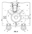
- FIG. 6 depicts a cross-sectional view of the corona treatment system along line 6 - 6 of FIG. 3 ;
- FIG. 7 depicts a cross-sectional view of the corona treatment system along line 7 - 7 of FIG. 3 ;
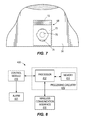
- FIG. 8 depicts a block view of a control system.
- the drawings illustrates a corona treatment system 20 which incorporates features of the present disclosure.
- the corona treatment system 20 may be adapted to be used in conjunction with a printing press (not shown).
- the corona treatment system 20 includes a cylindrical ground roller 22 , a high voltage electrode 24 , and a color sensor 26 for sensing imperfections on the surface 22 a of the ground roller 22 .
- Imperfections as defined herein are items on the ground roller 22 which change the reflectance level of the ground roller 22 from a predefined level. For example, imperfections can be caused by debris on the ground roller 22 , water on the ground roller 22 , oxidation on the ground roller 22 , pitting on the ground roller 22 .
- the corona treatment system 20 is used to modify a surface of a flexible web (not shown) to improve its ability to accept inks and adhesives.
- the web is passed between the ground roller 22 and the electrode 24 during which the material of web is treated to modify the material.
- Examples of webs that may be treated by the corona treatment system 20 include, but are not limited to, paper, polymer films, elastomers, plastics, foams, etc.
- the corona treatment system 20 includes a power supply cabinet 30 with a control panel 32 from which depends a first end plate 34 and, in parallel relationship thereto, a second end plate 36 , the ground roller 22 rotatably mounted between the plates 34 , 36 , the color sensor 26 in proximity to the ground roller 22 , an electrode support tube 38 mounted between the plates 34 , 36 , an electrode magazine 40 mounted on the electrode support tube 38 and supporting the high voltage electrode 24 in spaced relationship from the ground roller 22 , a plurality of idler rollers 42 rotatably mounted between the plates 34 , 36 and spaced from the ground roller 22 , and an apparatus 400 provided within the cabinet 30 which communicates with the color sensor 26 and controls a display and/or light 46 on the cabinet 30 .
- Tie bars 48 may be provided between the end plates 34 , 36 .
- the color sensor 26 is in proximity to the ground roller 22 so that the color sensor 26 can sense the reflectance levels of the ground roller 22 .
- the color sensor 26 may be mounted on one of the end plates; as shown, the color sensor 26 is mounted on end plate 34 ; the color sensor 26 may be mounted on the ground.
- the electrode support tube 38 and electrode magazine 40 mounted thereon may be pivotally connected to the end plates 34 , 36 as is known in the art.
- the electrode magazine 40 may be slidably mounted on the electrode support tube 38 as is known in the art. This allows the electrode magazine 40 to be moved between an inoperative or maintenance position, and an operative or web treating position.
- the electrode support tube 38 is hollow and has an open end 50 .
- the electrode support tube 38 has a plurality of apertures 52 therethrough which face the ground roller 22 . Venting of ozone generated during the corona treatment and cooling for the electrode 24 is provided by the path formed by the apertures 52 , the electrode support tube 38 and its open end 50 in a known manner.
- the electrode magazine 40 has a pair of shields 54 , 56 which are connected to the electrode support tube 38 , and support tubes 58 for supporting the electrode 24 between the shields 54 , 56 .
- the shields 54 , 56 aid in guiding the ozone to be vented through the electrode support tube 38 .
- the electrode 24 may be a plurality of parallel electrodes; the electrode 24 may be a ceramic electrode, a FIN electrode, a segmented electrode, as is known in the art.
- the ground roller 22 is mounted for a rotation on a shaft 60 between the end plates 34 , 36 and is positioned beneath the support tube 22 and beneath the electrode 24 .
- the electrode 24 may span the length of the ground roller 22 .
- the ground roller 22 and the electrode 24 may be spaced 1.5 mm away from each other to form an air gap 62 , see FIGS. 5 and 6 .
- Ground rollers used in corona treatment systems are known in the art.
- the ground roller 22 may have a surface 22 a formed of steel, ceramic, rubber, etc.
- the ground roller 22 may be formed of a self-supporting tube of a rigid dielectric material, such as a glass fiber reinforced epoxy or a glass fiber reinforced polymeric polyester.
- a conductive layer may be bonded to an inner wall of the ground roller 22 .
- the conductive layer is a relatively thin conductive metallic film or a coating containing a conductor, such as graphite.
- the conductive layer is relatively thin and does not have to be self-supporting because it is
- the idler rollers 42 are mounted for rotation on respective shafts 64 between the end plates 34 , 36 , and lie in space relationship below the ground roller 22 .
- the power supply cabinet 30 includes a power supply and a high voltage transformer provided with a high voltage wire.
- the wire terminates in a high voltage connection normally enclosed by a high voltage cover plate located behind the end plate 34 .
- the high voltage connection establishes a high voltage field between the ground roller 22 and the electrode 24 with the web to be treated interposed between the electrode 24 and the ground roller 22 .
- the high voltage field establishes a corona discharge that causes the chemical composition of the material of the web to be modified which, in turn, improves selected characteristics of the material of the web such as wettability so that printed matter or coating may be more advantageously adhered thereto.
- the web is guided upwardly by the idler rollers 42 and wound about the ground roller 22 in spaced relationship from the electrode 24 .
- the web does not span the entire length of the ground roller 22 such that there is a portion 66 exposed at at least one end of the ground roller 22 .
- the electrode 24 spans this portion 66 such that the surface 22 a of this portion 66 of the ground roller 22 is subjected to the high voltage from the electrode 24 .
- the ground roller 22 supports the web which is treated as it passes through the air gap 62 between the ground roller 22 and the electrode 24 in a direction transverse to the longitudinal direction of the electrode 24 .
- the air gap 62 between the two electrodes 22 , 24 is normally about 1.5 mm wide and a corona discharge develops in the air gap 62 when the electrode 24 is energized by the power supply to create a high voltage.
- the surface of the web passing through the air gap 62 is modified by the exposure to the corona so that its printing properties are improved.
- the high frequency voltage generated by the electrode 24 is also applied to the ground roller 22 . This causes the ground roller 22 to be heated which causes imperfections, such as oxidation and pitting, on the surface 22 a of the ground roller 22 . These imperfections will be present on the portion 66 of the ground roller 22 and are detected by the color sensor 24 .
- the color sensor 26 has a specific reflectance monitoring capacity and is mounted at a defined distance D from the ground roller 22 .
- the color sensor 26 is resistant to dust, water, debris, heat and ozone; such a sensor is commonly designated as a IP64 sensor.
- the color sensor 26 may be mounted in a variety of positions relative to the circumference of the ground roller 22 as shown in FIG. 6 . As shown in FIG. 6 , the color sensor 26 (shown in full line) may mounted so as to be generally diametrically opposed to the electrode 24 . The color sensor 26 is spaced a minimum at an angle ⁇ which is 45 degrees away from the electrode 24 as shown in FIG. 6 . A variety of mounting positions for the color sensor 26 are shown in FIG. 6 , but the sensor 26 can be mounted at any position around the circumference of the ground roller 22 through the arc shown by arrow ⁇ .
- the color sensor 26 illuminates the portion 66 of the surface of the ground roller 22 with white light and captures and analyzes the reflected color values.
- the color sensor 26 is pre-programmed to recognize a base reflectance state at the ground roller 22 which represents a “clean” appearance of the ground roller 22 , that is a state where there are no imperfections on the ground roller 22 .
- the color sensor 26 is pre-programmed to recognize an “unacceptable reflectance state” at the ground roller 22 representing a threshold contaminated appearance of the ground roller 22 , that is, when there are imperfections on the ground roller 22 .
- a signal is sent from the color sensor 26 to the apparatus 400 to activate an alarm 401 and/or to cease operation of the corona treatment system 20 .
- An example of a suitable color sensor 26 is sold under the tradename colorSENSOR 26 OT-3-MA sold by MICRO-EPSILON MESSTECHNIK GmbH & Co. KG.
- the color sensor 26 is positioned such that the color sensor 26 directs its light beam onto the portion 66 of the ground roller 22 that is not covered by the web during the corona treatment of the web. As shown, the color sensor 26 is positioned proximate to an end of the ground roller 22 .
- the color sensor 26 may be mounted on an arm 68 extending from the end plate 34 .
- the arm 68 of the color sensor 26 is moveable relative to the end plate 34 so that the color sensor 26 can be moved toward or away from the ground roller 22 a predetermined distance, for example, the color sensor 26 may be positioned 2 to 5 inches away from the ground roller 22 to provide a sensing diameter of 0.5 inches to 2 inches on the ground roller 22 ; the sensing diameter is dependent upon the diameter of the ground roller 22 .
- the arm 68 can be moved, thus moving the color sensor 26 , and then fixed into a new position relative to the end plate 34 .
- the color sensor 26 may be moved to accommodate differently sized ground rollers and to minimize any shadowing.
- the arm 68 has a first portion 70 which abuts against the end plate 34 , and a second portion 72 which is perpendicular to the first portion 70 .
- the first portion 70 has a slot 74 through which a fastener 76 is seated.
- the fastener 76 is threaded into an aperture in the end plate 34 .
- the color sensor 26 is attached to the free end of the second arm 68 . To change the position of the color sensor 26 relative to the ground roller 22 , the fastener 76 is loosened so that the arm 68 can be moved relative to the end plate 34 .
- the color sensor 26 is used to sense a specific level of reflectance at the ground roller 22 and this information is supplied to the apparatus 400 which alerts an operator by an alarm 401 , and/or is used by the apparatus 400 to cease the operation of the corona treatment system 20 .
- the alarm 401 may take the form of an audible signal, a light, a combination of an audible signal and light, etc.
- the triggering of the alarm 401 may also be used by the apparatus 400 to cease operation of the corona treatment system 20 . Once the operator is notified, the operator will then know that the ground roller 22 needs to be serviced.
- sensors such as a sensor (not shown) that detects air flow and a sensor (not shown) that detects the speed of the ground roller 22 , may be provided in the corona treatment system 20 .
- FIG. 8 illustrates a block diagram of an apparatus 400 that may be implemented on the corona treatment system 20 , in accordance with some example embodiments.
- apparatus 400 may enable the corona treatment system 20 to analyze information from the color sensor 26 to activate the alarm 401 and/or cease operation of the corona treatment system 20 in accordance with one or more example embodiments.
- the components, devices or elements illustrated in and described with respect to FIG. 8 below may not be mandatory and thus some may be omitted in certain embodiments. Additionally, some embodiments may include further or different components, devices or elements beyond those illustrated in and described with respect to FIG. 8 .
- the apparatus 400 may include processing circuitry 410 that is configurable to perform actions in accordance with one or more example embodiments disclosed herein.
- the processing circuitry 410 may be configured to perform and/or control performance of one or more functionalities of the corona treatment system 20 , such as actuating the roller 22 and the electrode 24 , activating the color sensor 26 and analyzing the information from the color sensor 26 to activate the alarm 401 and/or cease operation of the corona treatment system 20 in accordance with various example embodiments.
- the processing circuitry 410 may be configured to perform data processing, application execution and/or other processing and management services according to one or more example embodiments.
- the apparatus 400 or a portion(s) or component(s) thereof, such as the processing circuitry 410 may include one or more chipsets and/or other components that may be provided by integrated circuits.
- the processing circuitry 410 may include a processor 412 and, in some embodiments, such as that illustrated in FIG. 8 , may further include memory 414 .
- the processing circuitry 410 may be in communication with or otherwise control a wireless communication interface 416 in communication with the color sensor 26 (the color sensor 26 may be hard wired to the processing circuitry 410 and/or control module 418 .
- the processor 412 may be embodied in a variety of forms.
- the processor 412 may be embodied as various hardware-based processing means such as a microprocessor, a coprocessor, a controller or various other computing or processing devices including integrated circuits such as, for example, an ASIC (application specific integrated circuit), an FPGA (field programmable gate array), some combination thereof, or the like.
- ASIC application specific integrated circuit
- FPGA field programmable gate array
- the processor 412 may comprise a plurality of processors. The plurality of processors may be in operative communication with each other and may be collectively configured to perform one or more functionalities of the apparatus 400 as described herein.
- the processor 412 may be configured to execute instructions that may be stored in the memory 414 or that may be otherwise accessible to the processor 412 . As such, whether configured by hardware or by a combination of hardware and software, the processor 412 capable of performing operations according to various embodiments while configured accordingly.
- the memory 414 may include one or more memory devices. Memory 414 may include fixed and/or removable memory devices. In some embodiments, the memory 414 may provide a non-transitory computer-readable storage medium that may store computer program instructions that may be executed by the processor 412 . In this regard, the memory 414 may be configured to store information, data, applications, instructions and/or the like for enabling the apparatus 400 to carry out various functions in accordance with one or more example embodiments. In some embodiments, the memory 414 may be in communication with one or more of the processor 412 and transmission power control module 418 via one or more buses for passing information among components of the apparatus 400 .
- the apparatus 400 may further include circuitry, hardware, a computer program product comprising a computer readable medium (for example, the memory 414 ) storing computer readable program instructions that are executable by a processing device (for example, the processor 412 ), or some combination thereof.
- the processor 412 (or the processing circuitry 410 ) may include, or otherwise control the transmission power control module 418 .
Abstract
According to an aspect of the present disclosure, a color sensor is provided for sensing whether a ground roller in a corona treatment system needs to be serviced. The color sensor is capable of detecting imperfections which have changed the reflectance level of the ground roller from a predefined level. According to another aspect of the present disclosure, if a determination is made that the ground roller needs to be serviced, then an alarm is activated and/or the operation of the corona treatment system is ceased.
Description
The present invention relates generally to corona treatment of a web. More particularly, it relates to a color sensor capable of detecting imperfections on a ground roller used in a corona treatment system, to indicate that the ground roller needs to be serviced.
Corona treatment is a method using an electrical corona discharge to modify a surface of a web to improve its ability to accept inks and adhesives. In a corona treatment, a high voltage electrode is mounted parallel to and spaced from a ground roller, which forms a grounded electrode. The air gap between the electrodes is energized, forming a corona, which, when web is passed therethrough modifies the material the web is formed of, and makes the web more receptive to ink and adhesives. Corona will be produced anywhere there is air within this air gap.
The occurrence known as “backside treat” is the result of a corona being produced on both sides of a web being treated, even though the corona treatment system is only intended to treat one side of the web. The resulting undesired treatment on the backside of the web may result in blocking and picking. The resulting undesired treatment on the backside of the web may also cause an insufficient treat level on the side of the web requiring treatment, since some the power intended for treating the web was delivered to the opposite side, thus, reducing the watt density provided to the side to be treated.
There are a number of causes for backside treat, all of which are the result of air being entrapped under the web being treated. One of the most common causes for backside treat is dirt buildup on the corona ground roll. Regardless if the corona treatment system is a bare roll or a covered roll, dirt buildup gets deposited on the surface of the ground roller. These uneven deposits of dirt buildup lift the web off the surface of the ground roller, entrapping air underneath the web. To eliminate backside treat caused by dirt buildup, the ground roller must be cleaned.
In one aspect, a color sensor capable of detecting whether a ground roller used in a corona treatment system needs to be serviced is provided. The color sensor is capable of detecting imperfections which have changed the reflectance level of the ground roller from a predefined level.
In another aspect, if a determination is made that the ground roller needs to be serviced, then an alarm is activated and/or the operation of the corona treatment system is ceased.
The scope of the present invention is defined solely by the appended claims and is not affected by the statements within this summary.
The invention can be better understood with reference to the following drawings and description. The components in the figures are not necessarily to scale, emphasis instead being placed upon illustrating the principles of the invention.
While the invention may be susceptible to embodiment in different forms, there is shown in the drawings, and herein will be described in detail, specific embodiments with the understanding that the present disclosure is to be considered an exemplification of the principles of the invention, and is not intended to limit the invention to that as illustrated and described herein. Therefore, unless otherwise noted, features disclosed herein may be combined together to form additional combinations that were not otherwise shown for purposes of brevity.
The drawings illustrates a corona treatment system 20 which incorporates features of the present disclosure. The corona treatment system 20 may be adapted to be used in conjunction with a printing press (not shown). The corona treatment system 20 includes a cylindrical ground roller 22, a high voltage electrode 24, and a color sensor 26 for sensing imperfections on the surface 22 a of the ground roller 22. Imperfections as defined herein are items on the ground roller 22 which change the reflectance level of the ground roller 22 from a predefined level. For example, imperfections can be caused by debris on the ground roller 22, water on the ground roller 22, oxidation on the ground roller 22, pitting on the ground roller 22. The corona treatment system 20 is used to modify a surface of a flexible web (not shown) to improve its ability to accept inks and adhesives. The web is passed between the ground roller 22 and the electrode 24 during which the material of web is treated to modify the material. Examples of webs that may be treated by the corona treatment system 20 include, but are not limited to, paper, polymer films, elastomers, plastics, foams, etc.
In general, the corona treatment system 20 includes a power supply cabinet 30 with a control panel 32 from which depends a first end plate 34 and, in parallel relationship thereto, a second end plate 36, the ground roller 22 rotatably mounted between the plates 34, 36, the color sensor 26 in proximity to the ground roller 22, an electrode support tube 38 mounted between the plates 34, 36, an electrode magazine 40 mounted on the electrode support tube 38 and supporting the high voltage electrode 24 in spaced relationship from the ground roller 22, a plurality of idler rollers 42 rotatably mounted between the plates 34, 36 and spaced from the ground roller 22, and an apparatus 400 provided within the cabinet 30 which communicates with the color sensor 26 and controls a display and/or light 46 on the cabinet 30. Tie bars 48 may be provided between the end plates 34, 36. The color sensor 26 is in proximity to the ground roller 22 so that the color sensor 26 can sense the reflectance levels of the ground roller 22. The color sensor 26 may be mounted on one of the end plates; as shown, the color sensor 26 is mounted on end plate 34; the color sensor 26 may be mounted on the ground.
The electrode support tube 38 and electrode magazine 40 mounted thereon may be pivotally connected to the end plates 34, 36 as is known in the art. Alternatively, the electrode magazine 40 may be slidably mounted on the electrode support tube 38 as is known in the art. This allows the electrode magazine 40 to be moved between an inoperative or maintenance position, and an operative or web treating position. The electrode support tube 38 is hollow and has an open end 50. The electrode support tube 38 has a plurality of apertures 52 therethrough which face the ground roller 22. Venting of ozone generated during the corona treatment and cooling for the electrode 24 is provided by the path formed by the apertures 52, the electrode support tube 38 and its open end 50 in a known manner.
The electrode magazine 40 has a pair of shields 54, 56 which are connected to the electrode support tube 38, and support tubes 58 for supporting the electrode 24 between the shields 54, 56. As such, the shields 54, 56 aid in guiding the ozone to be vented through the electrode support tube 38.
The electrode 24 may be a plurality of parallel electrodes; the electrode 24 may be a ceramic electrode, a FIN electrode, a segmented electrode, as is known in the art.
The ground roller 22 is mounted for a rotation on a shaft 60 between the end plates 34, 36 and is positioned beneath the support tube 22 and beneath the electrode 24. The electrode 24 may span the length of the ground roller 22. The ground roller 22 and the electrode 24 may be spaced 1.5 mm away from each other to form an air gap 62, see FIGS. 5 and 6 . Ground rollers used in corona treatment systems are known in the art. The ground roller 22 may have a surface 22 a formed of steel, ceramic, rubber, etc. The ground roller 22 may be formed of a self-supporting tube of a rigid dielectric material, such as a glass fiber reinforced epoxy or a glass fiber reinforced polymeric polyester. A conductive layer may be bonded to an inner wall of the ground roller 22. The conductive layer is a relatively thin conductive metallic film or a coating containing a conductor, such as graphite. The conductive layer is relatively thin and does not have to be self-supporting because it is supported by the inner wall of the roller.
The idler rollers 42 are mounted for rotation on respective shafts 64 between the end plates 34, 36, and lie in space relationship below the ground roller 22.
The power supply cabinet 30 includes a power supply and a high voltage transformer provided with a high voltage wire. The wire terminates in a high voltage connection normally enclosed by a high voltage cover plate located behind the end plate 34. The high voltage connection establishes a high voltage field between the ground roller 22 and the electrode 24 with the web to be treated interposed between the electrode 24 and the ground roller 22. As is well known, the high voltage field establishes a corona discharge that causes the chemical composition of the material of the web to be modified which, in turn, improves selected characteristics of the material of the web such as wettability so that printed matter or coating may be more advantageously adhered thereto.
In use, the web is guided upwardly by the idler rollers 42 and wound about the ground roller 22 in spaced relationship from the electrode 24. The web does not span the entire length of the ground roller 22 such that there is a portion 66 exposed at at least one end of the ground roller 22. The electrode 24 spans this portion 66 such that the surface 22 a of this portion 66 of the ground roller 22 is subjected to the high voltage from the electrode 24. The ground roller 22 supports the web which is treated as it passes through the air gap 62 between the ground roller 22 and the electrode 24 in a direction transverse to the longitudinal direction of the electrode 24. The air gap 62 between the two electrodes 22, 24 is normally about 1.5 mm wide and a corona discharge develops in the air gap 62 when the electrode 24 is energized by the power supply to create a high voltage. The surface of the web passing through the air gap 62 is modified by the exposure to the corona so that its printing properties are improved. However, the high frequency voltage generated by the electrode 24 is also applied to the ground roller 22. This causes the ground roller 22 to be heated which causes imperfections, such as oxidation and pitting, on the surface 22 a of the ground roller 22. These imperfections will be present on the portion 66 of the ground roller 22 and are detected by the color sensor 24.
The color sensor 26 has a specific reflectance monitoring capacity and is mounted at a defined distance D from the ground roller 22. The color sensor 26 is resistant to dust, water, debris, heat and ozone; such a sensor is commonly designated as a IP64 sensor. The color sensor 26 may be mounted in a variety of positions relative to the circumference of the ground roller 22 as shown in FIG. 6 . As shown in FIG. 6 , the color sensor 26 (shown in full line) may mounted so as to be generally diametrically opposed to the electrode 24. The color sensor 26 is spaced a minimum at an angle α which is 45 degrees away from the electrode 24 as shown in FIG. 6 . A variety of mounting positions for the color sensor 26 are shown in FIG. 6 , but the sensor 26 can be mounted at any position around the circumference of the ground roller 22 through the arc shown by arrow β.
The color sensor 26 illuminates the portion 66 of the surface of the ground roller 22 with white light and captures and analyzes the reflected color values. The color sensor 26 is pre-programmed to recognize a base reflectance state at the ground roller 22 which represents a “clean” appearance of the ground roller 22, that is a state where there are no imperfections on the ground roller 22. The color sensor 26 is pre-programmed to recognize an “unacceptable reflectance state” at the ground roller 22 representing a threshold contaminated appearance of the ground roller 22, that is, when there are imperfections on the ground roller 22. Since the imperfections will be present on the portion 66 of the ground roller 22, once the portion 66 of the ground roller 22 proximate to the color sensor 26 reaches the unacceptable reflectance state, a signal is sent from the color sensor 26 to the apparatus 400 to activate an alarm 401 and/or to cease operation of the corona treatment system 20. An example of a suitable color sensor 26 is sold under the tradename colorSENSOR 26 OT-3-MA sold by MICRO-EPSILON MESSTECHNIK GmbH & Co. KG.
The color sensor 26 is positioned such that the color sensor 26 directs its light beam onto the portion 66 of the ground roller 22 that is not covered by the web during the corona treatment of the web. As shown, the color sensor 26 is positioned proximate to an end of the ground roller 22.
The color sensor 26 may be mounted on an arm 68 extending from the end plate 34. The arm 68 of the color sensor 26 is moveable relative to the end plate 34 so that the color sensor 26 can be moved toward or away from the ground roller 22 a predetermined distance, for example, the color sensor 26 may be positioned 2 to 5 inches away from the ground roller 22 to provide a sensing diameter of 0.5 inches to 2 inches on the ground roller 22; the sensing diameter is dependent upon the diameter of the ground roller 22. The arm 68 can be moved, thus moving the color sensor 26, and then fixed into a new position relative to the end plate 34. The color sensor 26 may be moved to accommodate differently sized ground rollers and to minimize any shadowing.
As shown, the arm 68 has a first portion 70 which abuts against the end plate 34, and a second portion 72 which is perpendicular to the first portion 70. As shown in FIG. 7 , the first portion 70 has a slot 74 through which a fastener 76 is seated. The fastener 76 is threaded into an aperture in the end plate 34. The color sensor 26 is attached to the free end of the second arm 68. To change the position of the color sensor 26 relative to the ground roller 22, the fastener 76 is loosened so that the arm 68 can be moved relative to the end plate 34. This allows the fastener 76 to translate within the slot 74, thereby allowing the arm 68 and color sensor 26 to move to a new position. Once the color sensor 26 is positioned in a desired new position, the fastener 76 is secured to prevent further relative movement between the arm 68/color sensor 26 and the end plate 34. The slot 74 could instead be provided on the end plate 34, with the aperture in the arm 68. It is to be understood that this structure for allowing relative movement between the color sensor 26 and end plate 34 is illustrative only and that many structures may be provided for allowing the relative movement between the color sensor 26 and end plate 34 which would be known to one of ordinary skill in the art.
As discussed, the color sensor 26 is used to sense a specific level of reflectance at the ground roller 22 and this information is supplied to the apparatus 400 which alerts an operator by an alarm 401, and/or is used by the apparatus 400 to cease the operation of the corona treatment system 20. The alarm 401 may take the form of an audible signal, a light, a combination of an audible signal and light, etc. The triggering of the alarm 401 may also be used by the apparatus 400 to cease operation of the corona treatment system 20. Once the operator is notified, the operator will then know that the ground roller 22 needs to be serviced.
Other sensors, such as a sensor (not shown) that detects air flow and a sensor (not shown) that detects the speed of the ground roller 22, may be provided in the corona treatment system 20.
In some example embodiments, the apparatus 400 may include processing circuitry 410 that is configurable to perform actions in accordance with one or more example embodiments disclosed herein. In this regard, the processing circuitry 410 may be configured to perform and/or control performance of one or more functionalities of the corona treatment system 20, such as actuating the roller 22 and the electrode 24, activating the color sensor 26 and analyzing the information from the color sensor 26 to activate the alarm 401 and/or cease operation of the corona treatment system 20 in accordance with various example embodiments. The processing circuitry 410 may be configured to perform data processing, application execution and/or other processing and management services according to one or more example embodiments.
In some embodiments, the apparatus 400 or a portion(s) or component(s) thereof, such as the processing circuitry 410, may include one or more chipsets and/or other components that may be provided by integrated circuits.
In some example embodiments, the processing circuitry 410 may include a processor 412 and, in some embodiments, such as that illustrated in FIG. 8 , may further include memory 414. The processing circuitry 410 may be in communication with or otherwise control a wireless communication interface 416 in communication with the color sensor 26 (the color sensor 26 may be hard wired to the processing circuitry 410 and/or control module 418.
The processor 412 may be embodied in a variety of forms. For example, the processor 412 may be embodied as various hardware-based processing means such as a microprocessor, a coprocessor, a controller or various other computing or processing devices including integrated circuits such as, for example, an ASIC (application specific integrated circuit), an FPGA (field programmable gate array), some combination thereof, or the like. Although illustrated as a single processor, it will be appreciated that the processor 412 may comprise a plurality of processors. The plurality of processors may be in operative communication with each other and may be collectively configured to perform one or more functionalities of the apparatus 400 as described herein. In some example embodiments, the processor 412 may be configured to execute instructions that may be stored in the memory 414 or that may be otherwise accessible to the processor 412. As such, whether configured by hardware or by a combination of hardware and software, the processor 412 capable of performing operations according to various embodiments while configured accordingly.
In some example embodiments, the memory 414 may include one or more memory devices. Memory 414 may include fixed and/or removable memory devices. In some embodiments, the memory 414 may provide a non-transitory computer-readable storage medium that may store computer program instructions that may be executed by the processor 412. In this regard, the memory 414 may be configured to store information, data, applications, instructions and/or the like for enabling the apparatus 400 to carry out various functions in accordance with one or more example embodiments. In some embodiments, the memory 414 may be in communication with one or more of the processor 412 and transmission power control module 418 via one or more buses for passing information among components of the apparatus 400.
The apparatus 400 may further include circuitry, hardware, a computer program product comprising a computer readable medium (for example, the memory 414) storing computer readable program instructions that are executable by a processing device (for example, the processor 412), or some combination thereof. In some embodiments, the processor 412 (or the processing circuitry 410) may include, or otherwise control the transmission power control module 418.
The Abstract is provided to allow the reader to quickly ascertain the nature of the technical disclosure. It is submitted with the understanding that it will not be used to interpret or limit the scope or meaning of the claims. In addition, in the foregoing Detailed Description, it can be seen that various features are grouped together in various embodiments for the purpose of streamlining the disclosure. This method of disclosure is not to be interpreted as reflecting an intention that the claimed embodiments require more features than are expressly recited in each claim. Rather, as the following claims reflect, inventive subject matter lies in less than all features of a single disclosed embodiment. Thus the following claims are hereby incorporated into the Detailed Description, with each claim standing on its own as a separately claimed subject matter.
While various embodiments of the invention have been described, it will be apparent to those of ordinary skill in the art that other embodiments and implementations are possible within the scope of the invention. Accordingly, the invention is not to be restricted except in light of the attached claims and their equivalents.
Claims (20)
1. A corona treatment system comprising:
an end plate;
a rotatable ground roller mounted to the end plate;
a high-voltage electrode mounted to the end plate and mounted proximate to the ground roller; and
a color sensor in proximity to the ground roller, the color sensor capable of detecting imperfections on the ground roller.
2. The corona treatment system of claim 1 , wherein the color sensor is mounted to the end plate.
3. The corona treatment system of claim 1 , further comprising a second end plate to which the ground roller is attached.
4. The corona treatment system of claim 2 , further comprising an arm to which the color sensor is mounted, the arm being connected to the end plate.
5. The corona treatment system of claim 2 , wherein the arm is movably mounted to the end plate such that the position of the color sensor relative to the ground roller can be changed.
6. The corona treatment system of claim 1 , wherein the color sensor is movable relative to the ground roller such that the position of the color sensor relative to the ground roller can be changed.
7. The corona treatment system of claim 1 , wherein the color sensor generally diametrically opposed to the electrode.
8. The corona treatment system of claim 1 , wherein the color sensor is positioned at an angle of 45 degrees or greater away from the electrode.
9. The corona treatment system of claim 1 , further comprising a controller in communication with the color sensor, and an alarm in communication with the controller, wherein upon determination by the color sensor that the ground roller has imperfections, a signal is sent to the controller which activates the alarm.
10. The corona treatment system of claim 9 , wherein the alarm is a light.
11. The corona treatment system of claim 9 , wherein the alarm is an audible signal.
12. The corona treatment system of claim 1 , further comprising a controller in communication with the color sensor, wherein upon determination by the color sensor that the ground roller has imperfections, a signal is sent to the controller which terminates operation of the electrode.
13. The corona treatment system of claim 1 , wherein the color sensor is positioned proximate to an end of the ground roller.
14. A corona treatment system comprising:
an end plate;
a rotatable ground roller mounted to the end plate;
a high-voltage electrode mounted to the end plate and mounted proximate to the ground roller; and
a color sensor mounted to the end plate, the color sensor mounted such that a light beam of the color sensor is directed onto the ground roller proximate to an end of the ground roller, the color sensor capable of detecting imperfections on the ground roller, the color sensor being movable relative to the ground roller such that the position of the color sensor relative to the ground roller can be changed;
a controller in communication with the color sensor; and
an alarm in communication with the controller, wherein upon determination by the color sensor that the ground roller has imperfections, a signal is sent to the controller which activates the alarm.
15. A method of operating a corona treatment system comprising:
activating a high-voltage electrode in proximity to a ground roller to form a corona;
rotating the ground roller to move a web past the high-voltage electrode; and
sensing imperfections on the ground roller.
16. The method of claim 15 , wherein a color sensor is used to send the imperfections on the ground roller.
17. The method of claim 15 , further comprising activating an alarm if the sensed imperfections exceed a predetermined level.
18. The method of claim 15 , further comprising ceasing operation of the electrode and ground roller if the sensed imperfections exceed a predetermined level.
19. The method of claim 15 , further comprising activating an audible signal if the sensed imperfections exceed a predetermined level.
20. The method of claim 15 , further comprising activating a visual signal if the sensed imperfections exceed a predetermined level.
Priority Applications (5)
| Application Number | Priority Date | Filing Date | Title |
|---|---|---|---|
| US15/016,807 US9856559B2 (en) | 2016-02-05 | 2016-02-05 | Corona treatment system |
| JP2018540406A JP6863995B2 (en) | 2016-02-05 | 2016-12-16 | Corona processing system |
| CN201680080695.6A CN109072524B (en) | 2016-02-05 | 2016-12-16 | Corona treatment system |
| EP16843242.5A EP3411518B1 (en) | 2016-02-05 | 2016-12-16 | Corona treatment system |
| PCT/US2016/067135 WO2017136050A1 (en) | 2016-02-05 | 2016-12-16 | Corona treatment system |
Applications Claiming Priority (1)
| Application Number | Priority Date | Filing Date | Title |
|---|---|---|---|
| US15/016,807 US9856559B2 (en) | 2016-02-05 | 2016-02-05 | Corona treatment system |
Publications (2)
| Publication Number | Publication Date |
|---|---|
| US20170226632A1 US20170226632A1 (en) | 2017-08-10 |
| US9856559B2 true US9856559B2 (en) | 2018-01-02 |
Family
ID=58228528
Family Applications (1)
| Application Number | Title | Priority Date | Filing Date |
|---|---|---|---|
| US15/016,807 Active 2036-07-13 US9856559B2 (en) | 2016-02-05 | 2016-02-05 | Corona treatment system |
Country Status (5)
| Country | Link |
|---|---|
| US (1) | US9856559B2 (en) |
| EP (1) | EP3411518B1 (en) |
| JP (1) | JP6863995B2 (en) |
| CN (1) | CN109072524B (en) |
| WO (1) | WO2017136050A1 (en) |
Families Citing this family (2)
| Publication number | Priority date | Publication date | Assignee | Title |
|---|---|---|---|---|
| CN108274784B (en) * | 2018-01-30 | 2024-02-02 | 吉林省煜玺工贸有限公司 | Corona treatment machine for silent adhesive tape |
| CN115847795B (en) * | 2022-12-30 | 2023-09-15 | 常州奥福电子设备有限公司 | Film corona machine with uniform corona gap |
Citations (8)
| Publication number | Priority date | Publication date | Assignee | Title |
|---|---|---|---|---|
| US5169450A (en) | 1991-04-18 | 1992-12-08 | American Roller Company | Corona treatment roller electrode |
| US5278409A (en) | 1992-11-12 | 1994-01-11 | Pillar Technologies | Electrode assembly positioning apparatus |
| US5293043A (en) | 1992-12-24 | 1994-03-08 | Pillar Technologies | Electrode assembly for a corona tester |
| US5332897A (en) | 1993-02-26 | 1994-07-26 | Corotec Corporation | Universal electrode for corona discharge surface treating |
| US5572304A (en) * | 1994-01-24 | 1996-11-05 | Ricoh Company, Ltd. | Intermediate image transfer element and image forming apparatus using the same |
| US6007784A (en) | 1997-07-11 | 1999-12-28 | 3Dt, Inc. | Electric discharge surface treating electrode and system |
| EP1187279A2 (en) | 2000-09-11 | 2002-03-13 | Illinois Tool Works Inc. | Narrow web corona treater |
| EP2211434A1 (en) | 2009-01-24 | 2010-07-28 | Afs Entwicklungs + Vertriebs Gmbh | Method and device for corona treatment |
Family Cites Families (8)
| Publication number | Priority date | Publication date | Assignee | Title |
|---|---|---|---|---|
| DE3622737C1 (en) * | 1986-07-05 | 1987-10-08 | Klaus Kalwar | Process for the corona treatment of web-like materials and device for carrying out the process |
| CN1035074C (en) * | 1991-07-12 | 1997-06-04 | 中国科学院物理研究所 | Treating method and device with plasma for fibre, fabric modifying |
| CA2301113A1 (en) * | 1998-06-17 | 1999-12-23 | Arcotec Oberflachentechnik Gmbh | Corona station for the preliminary processing of a strip material |
| AU2003902139A0 (en) * | 2003-05-05 | 2003-05-22 | Commonwealth Scientific And Industrial Research Organisation | Atmospheric pressure plasma treatment device and method |
| JP2010082915A (en) * | 2008-09-30 | 2010-04-15 | Sato Knowledge & Intellectual Property Institute | Label printer |
| US8482898B2 (en) * | 2010-04-30 | 2013-07-09 | Tessera, Inc. | Electrode conditioning in an electrohydrodynamic fluid accelerator device |
| CN104685391B (en) * | 2012-10-05 | 2017-03-08 | 住友化学株式会社 | The manufacture device of blooming and applying system |
| CN203931843U (en) * | 2014-02-27 | 2014-11-05 | 江苏中立方实业有限公司 | Capacitor thin film corona treatment plant |
-
2016
- 2016-02-05 US US15/016,807 patent/US9856559B2/en active Active
- 2016-12-16 CN CN201680080695.6A patent/CN109072524B/en not_active Expired - Fee Related
- 2016-12-16 JP JP2018540406A patent/JP6863995B2/en active Active
- 2016-12-16 EP EP16843242.5A patent/EP3411518B1/en active Active
- 2016-12-16 WO PCT/US2016/067135 patent/WO2017136050A1/en active Application Filing
Patent Citations (9)
| Publication number | Priority date | Publication date | Assignee | Title |
|---|---|---|---|---|
| US5169450A (en) | 1991-04-18 | 1992-12-08 | American Roller Company | Corona treatment roller electrode |
| US5278409A (en) | 1992-11-12 | 1994-01-11 | Pillar Technologies | Electrode assembly positioning apparatus |
| US5293043A (en) | 1992-12-24 | 1994-03-08 | Pillar Technologies | Electrode assembly for a corona tester |
| US5332897A (en) | 1993-02-26 | 1994-07-26 | Corotec Corporation | Universal electrode for corona discharge surface treating |
| US5572304A (en) * | 1994-01-24 | 1996-11-05 | Ricoh Company, Ltd. | Intermediate image transfer element and image forming apparatus using the same |
| US6007784A (en) | 1997-07-11 | 1999-12-28 | 3Dt, Inc. | Electric discharge surface treating electrode and system |
| EP1187279A2 (en) | 2000-09-11 | 2002-03-13 | Illinois Tool Works Inc. | Narrow web corona treater |
| US6894279B2 (en) | 2000-09-11 | 2005-05-17 | Illinois Tool Works Inc. | Narrow web corona treater |
| EP2211434A1 (en) | 2009-01-24 | 2010-07-28 | Afs Entwicklungs + Vertriebs Gmbh | Method and device for corona treatment |
Non-Patent Citations (3)
| Title |
|---|
| colorSENSOR OT-3-MA-30 Instruction Manual, Micro-Epsilon, 2008, 10 pages. |
| International Search Report and Written Opinion for International Patent Application No. PCT/US2016/067135 dated May 9, 2017, 13 pages. |
| OT-3-MA-50-12.5, OT-3-MA-50-25, Fixed Lens Color Sensors for Special Targets, colorSENSOR OT-3-MA, Micro-Epsilon, 2 pages. |
Also Published As
| Publication number | Publication date |
|---|---|
| JP2019511638A (en) | 2019-04-25 |
| WO2017136050A1 (en) | 2017-08-10 |
| EP3411518A1 (en) | 2018-12-12 |
| CN109072524B (en) | 2021-06-08 |
| JP6863995B2 (en) | 2021-04-21 |
| EP3411518B1 (en) | 2020-12-02 |
| US20170226632A1 (en) | 2017-08-10 |
| CN109072524A (en) | 2018-12-21 |
Similar Documents
| Publication | Publication Date | Title |
|---|---|---|
| EP3411518B1 (en) | Corona treatment system | |
| US20190240990A1 (en) | Printer | |
| JP2015510458A (en) | Corona treatment device | |
| EP2727735B1 (en) | Transportation device and recording apparatus | |
| CA2951304C (en) | Position adjustment mechanism for a corona treatment apparatus | |
| JP2008126667A (en) | Method for actuating apparatus optically measuring printing sheet | |
| JP5637022B2 (en) | Static elimination system, static elimination method, and web material processing apparatus | |
| JP2016184559A (en) | Electrode roll press device | |
| JP2021121475A (en) | Detection device and processing device | |
| CN113543975A (en) | Media height non-uniformity detection | |
| JP6672686B2 (en) | Medium transport device and image reading device | |
| US20180105975A1 (en) | Airfoil apparatus for a system having a controlled internal environment | |
| US9156291B2 (en) | Recording apparatus | |
| US11724522B2 (en) | Drying device, printing system | |
| KR101412199B1 (en) | Tube pump having leakage sensor | |
| JP2007021987A (en) | Method and apparatus for manufacture of ceramic green sheet | |
| JP7380131B2 (en) | Image forming apparatus, image forming apparatus control method, program | |
| CN109774311B (en) | Printing machine with printing beam for jetting ink | |
| JP5178113B2 (en) | Conductive material development processing method and conductive material development processing apparatus | |
| JP6514582B2 (en) | Remaining amount management device for roll-shaped tape member | |
| JP2021121552A (en) | Processing apparatus | |
| JP2015116763A (en) | Liquid discharge recording device and liquid discharge recording method | |
| JP6551078B2 (en) | Monitoring device | |
| JP6687879B2 (en) | Medium transport device | |
| JP2016088022A (en) | Recording device |
Legal Events
| Date | Code | Title | Description |
|---|---|---|---|
| AS | Assignment |
Owner name: ILLINOIS TOOL WORKS INC., ILLINOIS Free format text: ASSIGNMENT OF ASSIGNORS INTEREST;ASSIGNOR:WOLF, RORY A.;REEL/FRAME:037785/0725 Effective date: 20160204 |
|
| STCF | Information on status: patent grant |
Free format text: PATENTED CASE |
|
| MAFP | Maintenance fee payment |
Free format text: PAYMENT OF MAINTENANCE FEE, 4TH YEAR, LARGE ENTITY (ORIGINAL EVENT CODE: M1551); ENTITY STATUS OF PATENT OWNER: LARGE ENTITY Year of fee payment: 4 |