JP2015510458A - Corona treatment device - Google Patents
Corona treatment device Download PDFInfo
- Publication number
- JP2015510458A JP2015510458A JP2014551626A JP2014551626A JP2015510458A JP 2015510458 A JP2015510458 A JP 2015510458A JP 2014551626 A JP2014551626 A JP 2014551626A JP 2014551626 A JP2014551626 A JP 2014551626A JP 2015510458 A JP2015510458 A JP 2015510458A
- Authority
- JP
- Japan
- Prior art keywords
- sheet
- corona
- electrode
- guide element
- sheet guide
- Prior art date
- Legal status (The legal status is an assumption and is not a legal conclusion. Google has not performed a legal analysis and makes no representation as to the accuracy of the status listed.)
- Withdrawn
Links
Images


Classifications
-
- B—PERFORMING OPERATIONS; TRANSPORTING
- B41—PRINTING; LINING MACHINES; TYPEWRITERS; STAMPS
- B41J—TYPEWRITERS; SELECTIVE PRINTING MECHANISMS, i.e. MECHANISMS PRINTING OTHERWISE THAN FROM A FORME; CORRECTION OF TYPOGRAPHICAL ERRORS
- B41J2/00—Typewriters or selective printing mechanisms characterised by the printing or marking process for which they are designed
- B41J2/385—Typewriters or selective printing mechanisms characterised by the printing or marking process for which they are designed characterised by selective supply of electric current or selective application of magnetism to a printing or impression-transfer material
-
- H—ELECTRICITY
- H01—ELECTRIC ELEMENTS
- H01T—SPARK GAPS; OVERVOLTAGE ARRESTERS USING SPARK GAPS; SPARKING PLUGS; CORONA DEVICES; GENERATING IONS TO BE INTRODUCED INTO NON-ENCLOSED GASES
- H01T19/00—Devices providing for corona discharge
-
- B—PERFORMING OPERATIONS; TRANSPORTING
- B29—WORKING OF PLASTICS; WORKING OF SUBSTANCES IN A PLASTIC STATE IN GENERAL
- B29C—SHAPING OR JOINING OF PLASTICS; SHAPING OF MATERIAL IN A PLASTIC STATE, NOT OTHERWISE PROVIDED FOR; AFTER-TREATMENT OF THE SHAPED PRODUCTS, e.g. REPAIRING
- B29C59/00—Surface shaping of articles, e.g. embossing; Apparatus therefor
- B29C59/10—Surface shaping of articles, e.g. embossing; Apparatus therefor by electric discharge treatment
-
- H—ELECTRICITY
- H05—ELECTRIC TECHNIQUES NOT OTHERWISE PROVIDED FOR
- H05H—PLASMA TECHNIQUE; PRODUCTION OF ACCELERATED ELECTRICALLY-CHARGED PARTICLES OR OF NEUTRONS; PRODUCTION OR ACCELERATION OF NEUTRAL MOLECULAR OR ATOMIC BEAMS
- H05H1/00—Generating plasma; Handling plasma
- H05H1/24—Generating plasma
- H05H1/2406—Generating plasma using dielectric barrier discharges, i.e. with a dielectric interposed between the electrodes
-
- H—ELECTRICITY
- H05—ELECTRIC TECHNIQUES NOT OTHERWISE PROVIDED FOR
- H05H—PLASMA TECHNIQUE; PRODUCTION OF ACCELERATED ELECTRICALLY-CHARGED PARTICLES OR OF NEUTRONS; PRODUCTION OR ACCELERATION OF NEUTRAL MOLECULAR OR ATOMIC BEAMS
- H05H1/00—Generating plasma; Handling plasma
- H05H1/24—Generating plasma
- H05H1/47—Generating plasma using corona discharges
-
- B—PERFORMING OPERATIONS; TRANSPORTING
- B41—PRINTING; LINING MACHINES; TYPEWRITERS; STAMPS
- B41J—TYPEWRITERS; SELECTIVE PRINTING MECHANISMS, i.e. MECHANISMS PRINTING OTHERWISE THAN FROM A FORME; CORRECTION OF TYPOGRAPHICAL ERRORS
- B41J11/00—Devices or arrangements of selective printing mechanisms, e.g. ink-jet printers or thermal printers, for supporting or handling copy material in sheet or web form
- B41J11/0015—Devices or arrangements of selective printing mechanisms, e.g. ink-jet printers or thermal printers, for supporting or handling copy material in sheet or web form for treating before, during or after printing or for uniform coating or laminating the copy material before or after printing
Abstract
カットシート材を処理するためのコロナ処理装置が提供される。コロナ処理装置は:互いに近接したコロナ電極及び対極を含み、シートの表面にコロナプラズマ処理を施すためのコロナ手段;前記コロナ手段に亘って且つ前記コロナ電極と前記対極との間に位置する搬送経路の方向に、前記シートを搬送するためのシート搬送手段;及び前記コロナ手段に沿って前記シートをガイドするための複数のシートガイド要素;を含む。前記複数のシートガイド要素が前記コロナ電極と前記搬送経路との間に位置しているため、前記搬送経路と前記コロナ電極との間に所定の距離がもたらされている。本発明はさらに、そのようなコロナ処理装置を含む、カットシート材を処理するための印刷システムに関する。A corona treatment device for treating cut sheet material is provided. The corona treatment apparatus includes: a corona electrode and a counter electrode adjacent to each other, and corona means for performing corona plasma treatment on the surface of the sheet; a conveyance path located across the corona means and between the corona electrode and the counter electrode Sheet conveying means for conveying the sheet in the direction of; and a plurality of sheet guide elements for guiding the sheet along the corona means. Since the plurality of sheet guide elements are located between the corona electrode and the transport path, a predetermined distance is provided between the transport path and the corona electrode. The invention further relates to a printing system for processing a cut sheet material comprising such a corona treatment device.
Description
本発明はカットシート材を処理するためのコロナ処理装置に関する。本発明はさらにカットシート材を処理するためのコロナ処理装置を含む印刷システムに関する。 The present invention relates to a corona treatment apparatus for treating a cut sheet material. The present invention further relates to a printing system including a corona treatment device for processing cut sheet material.
材料を化学的に改質するコロナ処理の品質を制御するには、材料をコロナ処理の間に所定の距離で維持することが重要である。 In order to control the quality of the corona treatment that chemically modifies the material, it is important to maintain the material at a predetermined distance during the corona treatment.
ウェブ搬送経路の特定距離でコロナユニットを設置することによりコロナユニットの所定距離でウェブ供給シート材を維持することが広く知られている。そのため、ウェブ搬送経路の両側でウェブを引っ張ることにより、コロナユニットに沿ってウェブを搬送する間にウェブ供給シート材の距離が所定の距離で維持される。 It is widely known that the web supply sheet material is maintained at a predetermined distance of the corona unit by installing the corona unit at a specific distance in the web conveyance path. Therefore, by pulling the web on both sides of the web conveyance path, the distance of the web supply sheet material is maintained at a predetermined distance while the web is conveyed along the corona unit.
上記のウェブ搬送メカニズムの欠点は、コロナユニットに沿ってカットシート材を制御可能に搬送できないという点である。コロナユニットに沿って搬送する間、カットシート材の前端及び後端を常に制御することができないため、コロナユニットに対するカットシート材の距離が、コロナユニットに沿った搬送の間に変化し得る。その結果、カットシート材の表面のコロナ処理の品質が制御できない。他の欠点は、カットシートの厚さが異なる場合、カットシート材の搬送経路を調節しなければならない点である。他の欠点は、コロナユニットに沿った搬送の間にカットシート材がコロナユニットに当たって損傷を受けたり又は詰まったりすることがあるという点である。 The drawback of the web transport mechanism is that the cut sheet material cannot be transported controllably along the corona unit. Since the front end and the rear end of the cut sheet material cannot be controlled at all times while being conveyed along the corona unit, the distance of the cut sheet material relative to the corona unit may change during the conveyance along the corona unit. As a result, the quality of the corona treatment on the surface of the cut sheet material cannot be controlled. Another drawback is that when the thickness of the cut sheet is different, the conveyance path of the cut sheet material must be adjusted. Another disadvantage is that the cut sheet material may hit the corona unit and become damaged or jammed during transport along the corona unit.
米国特許出願第2004/0003475号には、移動中のシート又はウェブにイオン化空気を高速で放出する圧搾空気イオン化バー(pressurized air ionizing bar)を有するシート/ウェブ清浄器が開示されている。シート又はウェブが、細長い空気放出開口部に沿った経路に沿って搬送される。放出されたイオン化空気による処理は、シート又はウェブの双方の上に存在する静電気を中和するための電荷を処理中のシート材又はウェブ材に提供する。 U.S. Patent Application No. 2004/0003475 discloses a sheet / web cleaner having a compressed air ionizing bar that releases ionized air at a high rate onto a moving sheet or web. A sheet or web is conveyed along a path along the elongated air discharge opening. Treatment with the released ionized air provides the sheet or web material being processed with a charge to neutralize static electricity present on both the sheet or web.
欧州特許出願第0318284号には、導電性のシールドケース及びコロナワイヤ線を含むコロナ放電器が開示されている。ワイヤ線はシート材の裏面にコロナ放電を施す。シールドケースにシート材が入るのを防止するためにガイド体が設けられている。回転ドラム上のトナー像をシート材に転写するために又は回転ドラムの表面とシート材が密着した場合にシート材を剥離するために、コロナ放電器がシート材に電荷を提供する。 European Patent Application No. 0318284 discloses a corona discharger including a conductive shield case and a corona wire. The wire wire performs corona discharge on the back surface of the sheet material. A guide body is provided to prevent the sheet material from entering the shield case. In order to transfer the toner image on the rotating drum to the sheet material or to peel the sheet material when the surface of the rotating drum and the sheet material come into close contact with each other, a corona discharger provides a charge to the sheet material.
上記の周知の装置の欠点は、それらによる処理ではカットシート材の表面を化学的に改質できないという点である。 A drawback of the above known devices is that the surface of the cut sheet material cannot be chemically modified by treatment with them.
従って、本発明の目的は、カットシート材の表面を化学的に改質するために、該カットシート材を制御可能に処理するコロナ処理装置を提供することである。 Accordingly, an object of the present invention is to provide a corona treatment apparatus for controllably treating a cut sheet material in order to chemically modify the surface of the cut sheet material.
この目的は、カットシート材を処理するためのコロナ処理装置によって実現される。コロナ処理装置は:コロナ電極を含み、シートの表面にコロナ処理を施すためのコロナ手段;前記コロナ手段に沿った搬送経路の方向に、前記シートを搬送するためのシート搬送手段;及び前記コロナ手段に沿って前記シートをガイドするための複数のシートガイド要素;を含み、前記複数のシートガイド要素が前記コロナ電極と前記搬送経路との間に位置しているため、前記搬送経路と前記コロナ電極との間に所定の距離がもたらされ、前記複数のシートガイド要素は、シート搬送方向に対して第1の角度の方向に伸びた第1のシートガイド要素を少なくとも含む。 This object is achieved by a corona treatment device for treating cut sheet material. The corona treatment apparatus includes: a corona means including a corona electrode, and a corona means for performing corona treatment on the surface of the sheet; a sheet conveyance means for conveying the sheet in a direction of a conveyance path along the corona means; and the corona means A plurality of sheet guide elements for guiding the sheet along the line, and the plurality of sheet guide elements are positioned between the corona electrode and the conveyance path, so that the conveyance path and the corona electrode A plurality of sheet guide elements including at least a first sheet guide element extending in a direction at a first angle with respect to a sheet conveying direction.
前記のカットシート材を処理するためのコロナ処理装置の一実施形態では、コロナ処理装置は:互いに近接したコロナ電極及び対極を含み、シートの表面にコロナプラズマ処理を施すためのコロナ手段;前記コロナ手段に亘って且つ前記コロナ電極と前記対極との間に位置する搬送経路の方向に前記カットシート材を搬送するためのシート搬送手段;及び前記コロナ電極に沿って前記シートをガイドするための複数のシートガイド要素;を含み、前記複数のシートガイド要素が前記コロナ電極と前記搬送経路との間に位置しているため、前記搬送経路と前記コロナ電極との間に所定の距離がもたらされ、前記複数のシートガイド要素は、シート搬送方向に対して第1の角度の方向に伸びた第1のシートガイド要素を少なくとも含む。 In one embodiment of the corona treatment device for treating the cut sheet material, the corona treatment device comprises: a corona electrode and a counter electrode adjacent to each other, and corona means for subjecting the surface of the sheet to corona plasma treatment; Sheet conveying means for conveying the cut sheet material across the means and in the direction of the conveying path located between the corona electrode and the counter electrode; and a plurality for guiding the sheet along the corona electrode The plurality of sheet guide elements are located between the corona electrode and the transport path, thereby providing a predetermined distance between the transport path and the corona electrode. The plurality of sheet guide elements include at least a first sheet guide element extending in a direction at a first angle with respect to the sheet conveying direction.
前記コロナ処理装置はコロナ手段を含む。該コロナ手段はコロナ電極及び対極を含む。動作中、カットシート材は、コロナ電極に沿った搬送経路を介して、コロナ電極と対極との間を搬送される。コロナ手段は、コロナ電極と対極との間にプラズマを提供する。本発明に係るプラズマは、コロナ電極と対極との間を、搬送経路に沿って搬送されるシートの表面の方向に提供される。高圧の交流電場で均一なプラズマを提供するために、コロナ電極及び対極は、搬送経路の両側で互いに略平行に配置されていることが好ましい。 The corona treatment device includes corona means. The corona means includes a corona electrode and a counter electrode. During operation, the cut sheet material is conveyed between the corona electrode and the counter electrode via a conveyance path along the corona electrode. The corona means provides a plasma between the corona electrode and the counter electrode. The plasma according to the present invention is provided between the corona electrode and the counter electrode in the direction of the surface of the sheet conveyed along the conveyance path. In order to provide a uniform plasma with a high-voltage AC electric field, the corona electrode and the counter electrode are preferably disposed substantially parallel to each other on both sides of the transport path.
コロナ電極と対極との間で形成される本明細書で使用のプラズマは、カットシート材の表面を化学的に改質するために提供される。プラスチック、布又は紙等の材料の表面エネルギーを変化させるために、該材料をプラズマに通すことが、例えばフランス特許第2578176号及び英国特許第925354号から知られている。 The plasma used herein formed between the corona electrode and the counter electrode is provided to chemically modify the surface of the cut sheet material. In order to change the surface energy of materials such as plastic, cloth or paper, it is known to pass the material through a plasma, for example from French Patent No. 2578176 and British Patent No. 925354.
本発明によれば、カットシート材の表面をインクの液滴と相互作用するように適合させるために、本発明に係る複数のシートガイド要素を設けて、カットシート材を、制御可能な形でコロナ電極と対極との間を通過させると、プラズマがカットシート材の表面エネルギーを化学的に改質し得る。プラズマがカットシート材の表面エネルギーを改質し得るため、隣接するインクの液滴間で生じるにじみ(inter color bleed)が低減するか又は個々のインクの液滴のインク液滴拡散が広がる。搬送経路を介してカットシートを搬送する間に、コロナ電極と対極との間に高圧の交流電場を提供することにより、本明細書で使用のプラズマが形成されて、カットシートの表面に直接提供される。 According to the present invention, in order to adapt the surface of the cut sheet material to interact with the ink droplets, a plurality of sheet guide elements according to the present invention are provided to control the cut sheet material in a controllable manner. When passing between the corona electrode and the counter electrode, the plasma can chemically modify the surface energy of the cut sheet material. Since the plasma can modify the surface energy of the cut sheet material, the inter color bleed that occurs between adjacent ink droplets is reduced or the ink droplet diffusion of individual ink droplets is increased. By delivering a high-voltage AC electric field between the corona electrode and the counter electrode while conveying the cut sheet through the conveyance path, the plasma used in this specification is formed and provided directly on the surface of the cut sheet Is done.
コロナ電極は、セラミックバー、放電電極、湾曲電極(curved electrode)又は他の任意のコロナ放電要素であり得る。コロナ手段は複数のコロナ電極を含んでいてもよい。 The corona electrode can be a ceramic bar, a discharge electrode, a curved electrode or any other corona discharge element. The corona means may include a plurality of corona electrodes.
対極は電気的に接地されていることが好ましい。対極は、搬送経路のコロナ電極とは反対側に配置される。その結果、コロナ手段は、コロナ電極と対極との間の搬送経路でカットシートの表面にコロナプラズマ処理を施し得る。対極は平面を有していてもよいし、湾曲面を有していてもよい。対極の面の曲率がコロナ電極の面の曲率よりも小さいことが好ましい。対極は裸の導電面を有していてもよいし、誘電性の表層を含んでいてもよい。一実施形態では、カットシート材を搬送経路を介して搬送する間に支持するために、対極と搬送経路との間に誘電体シートの支持面が設けられ得る。 The counter electrode is preferably electrically grounded. The counter electrode is disposed on the opposite side of the conveyance path from the corona electrode. As a result, the corona means can perform corona plasma treatment on the surface of the cut sheet in the conveyance path between the corona electrode and the counter electrode. The counter electrode may have a flat surface or a curved surface. It is preferable that the curvature of the surface of the counter electrode is smaller than the curvature of the surface of the corona electrode. The counter electrode may have a bare conductive surface or may include a dielectric surface layer. In one embodiment, a support surface for the dielectric sheet may be provided between the counter electrode and the transport path to support the cut sheet material while it is transported through the transport path.
一実施形態では、シート搬送手段は、コロナ電極に沿った搬送経路の方向にシートを搬送するように構成されている。搬送経路はコロナ電極と対極との間に位置している。シート搬送手段は、シートを搬送経路の方向に押すこと及び/又はシートを搬送経路の方向に引っ張ることを行い得る。シート搬送手段は、搬送経路の入口位置の近くでシートを押すためのシート入力ピンチローラー(sheet input pinch roller)を含み得る。搬送経路は、対極側の支持面とシートガイド要素との間に高さを有する。搬送経路を介した搬送時のカットシート材の支持面は対極の外面であり得る。搬送経路の高さは1〜3mmの範囲にあることが好ましく、1〜1.5mmの範囲にあることがより好ましい。搬送経路の高さが3mmより大きくなると、コロナ電極に沿った搬送時にカットシート材が搬送経路において高さ方向に自由に動くことがあるため、シート材料のプラズマ処理が不均一になる。搬送経路の高さが1mmよりも大幅に小さいと、カットシート材は搬送中にシートガイド要素と対極との間で妨げられ得る。搬送されるカットシート材に対応するためには、搬送経路の最低高さが少なくともカットシート材の厚さと同じである。 In one embodiment, the sheet conveying means is configured to convey the sheet in the direction of the conveyance path along the corona electrode. The conveyance path is located between the corona electrode and the counter electrode. The sheet conveying means may perform pushing of the sheet in the direction of the conveying path and / or pulling of the sheet in the direction of the conveying path. The sheet conveying means may include a sheet input pinch roller for pushing the sheet near the entrance position of the conveying path. The conveyance path has a height between the support surface on the counter electrode side and the sheet guide element. The support surface of the cut sheet material during conveyance via the conveyance path can be the outer surface of the counter electrode. The height of the conveyance path is preferably in the range of 1 to 3 mm, and more preferably in the range of 1 to 1.5 mm. If the height of the conveyance path is greater than 3 mm, the cut sheet material may move freely in the height direction in the conveyance path during conveyance along the corona electrode, so that the plasma treatment of the sheet material becomes non-uniform. If the height of the conveyance path is significantly smaller than 1 mm, the cut sheet material can be blocked between the sheet guide element and the counter electrode during conveyance. In order to correspond to the cut sheet material to be conveyed, the minimum height of the conveyance path is at least the same as the thickness of the cut sheet material.
複数のシートガイド要素は、コロナ電極に沿った搬送経路に亘ってシートをガイドする。複数のシートガイド要素はコロナ電極と搬送経路との間に位置しているため、搬送経路とコロナ電極との間に所定の距離がもたらされる。その結果、ガイドされるシートはコロナ電極から所定の距離で維持される。この所定の距離は、カットシートの表面に均一なプラズマ処理を施すのに好適な距離である。コロナ手段による十分なプラズマ処理効果をもたらすために、この所定の距離は比較的短い。 The plurality of sheet guide elements guide the sheet along the conveyance path along the corona electrode. Since the plurality of sheet guide elements are positioned between the corona electrode and the conveyance path, a predetermined distance is provided between the conveyance path and the corona electrode. As a result, the guided sheet is maintained at a predetermined distance from the corona electrode. This predetermined distance is a distance suitable for performing a uniform plasma treatment on the surface of the cut sheet. This predetermined distance is relatively short in order to provide a sufficient plasma treatment effect by the corona means.
一実施形態では、前記所定の距離は1〜3mmの範囲にあり、1mm〜1.5mmの範囲にあることがより好ましく、特に、前記所定の距離は約1.25mmである。前記所定の距離がこの範囲にあると、コロナプラズマの強度及び均一性が、カットシート材の表面を均一に改質するのに十分なものとなる。複数のシートガイド要素のそれぞれはコロナ電極と搬送経路との間に配置され得る。そのため、各シートガイド要素は、コロナ電極のシート搬送方向の処理長の一部に亘って伸びているか又はコロナ電極のシート搬送方向の処理長の全体に亘って伸びるように配置され得る。シートガイド要素がコロナ電極の処理長に全体に亘って伸びている場合、搬送経路全体でのカットシート材の誘導が向上する。 In one embodiment, the predetermined distance is in the range of 1-3 mm, more preferably in the range of 1 mm-1.5 mm, in particular, the predetermined distance is about 1.25 mm. When the predetermined distance is within this range, the intensity and uniformity of the corona plasma are sufficient to uniformly modify the surface of the cut sheet material. Each of the plurality of sheet guide elements may be disposed between the corona electrode and the conveyance path. Therefore, each sheet guide element may be arranged to extend over a part of the processing length of the corona electrode in the sheet conveyance direction or to extend over the entire processing length of the corona electrode in the sheet conveyance direction. When the sheet guide element extends over the entire processing length of the corona electrode, the guidance of the cut sheet material in the entire conveying path is improved.
前記コロナ処理装置の一実施形態では、複数のシートガイド要素のそれぞれはセラミック材料を含む。セラミック材料はプラズマに対して十分な不活性を有しており(化学的に安定)、コロナ手段によって形成されたプラズマを劣化させない。本明細書で用いるセラミック材料は電気絶縁材料である。シートガイド要素が、スチール又はアルミ等の導電性の表面材料を有していると、シートガイド要素がコロナプラズマの均一性を劣化させる。セラミック材料は複数のシートガイド要素の耐久性をサポートするため、寿命がある間所定の距離が維持されつつ、コロナプラズマ処理工程が向上する。複数のシートガイド要素のそれぞれはセラミック表層を含み得る。あるいは、複数のシートガイド要素のそれぞれはセラミック材料で構成され得る。セラミック材料は、例えば酸化アルミニウム(Al2O3)、窒化ケイ素(Si3N4)又は炭化ケイ素(SiC)であり得る。 In one embodiment of the corona treatment device, each of the plurality of sheet guide elements comprises a ceramic material. The ceramic material is sufficiently inert to the plasma (chemically stable) and does not degrade the plasma formed by the corona means. The ceramic material used herein is an electrically insulating material. If the sheet guide element has a conductive surface material such as steel or aluminum, the sheet guide element degrades the uniformity of the corona plasma. Since the ceramic material supports the durability of the plurality of sheet guide elements, the corona plasma treatment process is improved while maintaining a predetermined distance for the lifetime. Each of the plurality of sheet guide elements may include a ceramic surface layer. Alternatively, each of the plurality of sheet guide elements can be composed of a ceramic material. The ceramic material can be, for example, aluminum oxide (Al 2 O 3 ), silicon nitride (Si 3 N 4 ), or silicon carbide (SiC).
前記コロナ処理装置の一実施形態では、複数のシートガイド要素は、搬送経路の平面内でシート搬送方向に対して第1の角度の方向に伸びた第1のシートガイド要素を少なくとも含む。シートガイド要素の角度は、シートガイド要素の幅Wguidと共に、コロナ手段のシート搬送方向のコロナプラズマ処理長Lcoronaのうちのどの部分がシートガイド要素で覆われるかを規定し、コロナ手段のコロナプラズマ処理長Lcoronaの最大で20%が覆われる。 In one embodiment of the corona treatment device, the plurality of sheet guide elements include at least a first sheet guide element extending in a first angle direction with respect to the sheet conveyance direction in the plane of the conveyance path. Angle of the seat guide element, together with the width W guid sheet guiding element, which part of the corona plasma treatment length L corona sheet conveying direction of the corona means define either covered with a sheet guide element, Corona Corona means A maximum of 20% of the plasma treatment length L corona is covered.
複数のシートガイド要素は、シート搬送方向に対して第1の角度で配置された方向に伸びた第1のシートガイド要素を少なくとも含む。一実施形態では、少なくとも第1のシートガイド要素は、2つ以上のシートガイド要素を含むサブセットであり得る。シート搬送方向に対する少なくとも第1のシートガイド要素の角度が少なくとも0より大きいことが好ましい。少なくとも第1のシートガイド要素の角度は、搬送経路と平行な面内の角度である。シートの搬送経路はコロナ放電方向に略垂直であり得る。 The plurality of sheet guide elements include at least a first sheet guide element extending in a direction arranged at a first angle with respect to the sheet conveyance direction. In one embodiment, at least the first sheet guide element may be a subset that includes two or more sheet guide elements. It is preferable that the angle of at least the first sheet guide element with respect to the sheet conveyance direction is at least larger than zero. The angle of at least the first sheet guide element is an angle in a plane parallel to the conveyance path. The sheet conveyance path may be substantially perpendicular to the corona discharge direction.
前記の角度が0で、シートガイド要素がコロナ手段の全コロナプラズマ処理長に亘って伸びている場合、コロナユニットに沿ってシートを搬送する間、ガイド要素がシートの表面の一部をコロナ手段から常に遮蔽するため、シートのそれらの部分はプラズマによる処理を受けない。 If the angle is 0 and the sheet guide element extends over the entire corona plasma treatment length of the corona means, the guide element will partially correlate the surface of the sheet while transporting the sheet along the corona unit. Those parts of the sheet are not treated with plasma because they are always shielded from.
少なくとも第1のシートガイド要素の第1の角度は、動作時に、シートの表面全体にコロナ処理が施されるように選択される。コロナ手段が特定のコロナプラズマ処理有効長(effective corona plasma length)Lcoronaを有し、シートガイド要素が特定の幅Wguidを有する場合、少なくとも第1のシートガイド要素の角度は、十分に長い距離及び/又は時間に亘りシートがコロナ手段によってプラズマ処理されるように選択される。 At least the first angle of the first sheet guide element is selected such that, in operation, the entire surface of the sheet is corona treated. Corona means has a specific corona plasma treatment effective length (effective corona plasma length) L corona , if the sheet guide element has a certain width W guid, angle of at least a first sheet guide element is sufficiently long distance And / or is selected such that the sheet is plasma treated by corona means over time.
前記コロナ処理装置の一実施形態では、シートガイド要素の角度は、シートガイド要素の幅Wguidと共に、コロナ手段のシート搬送方向の処理長Lcoronaのうちのどの部分がシートガイド要素で覆われるかを規定し、コロナ手段の処理長Lcoronaの最大で20%が覆われる。 Or In one embodiment of the corona treatment apparatus, the angle of the sheet guide element, together with the width W guid sheet guiding element, which portion of the sheet conveying direction of the processing length L corona corona means is covered with a sheet guide element And a maximum of 20% of the treatment length L corona of the corona means is covered.
そのため、コロナプラズマ処理長Lcoronaに亘ってシート搬送方向にカットシートを搬送する間に、カットシートの表面の特定の位置では最大で20%がシートガイド要素で覆われ、表面の前記位置を処理するのにコロナ手段の長さの少なくとも80%が有効に用いられるように、前記角度が好適に選択される。そのため、シートガイド要素の幅Wguidが増加したか又はコロナ手段のコロナプラズマ処理長Lcoronaが減少した場合、角度を増やして十分な表面処理が確実になるようにしてもよい。 Therefore, while a cut sheet is conveyed in the sheet conveyance direction over the corona plasma processing length L corona , a maximum of 20% is covered with a sheet guide element at a specific position on the surface of the cut sheet, and the position on the surface is processed. The angle is preferably selected so that at least 80% of the length of the corona means is effectively used for this purpose. Therefore, if the corona plasma treatment length L corona whether or corona unit width W guid of the sheet guide element is increased is reduced, sufficient surface treatment to increase the angle may be set to be ensured.
コロナ電極が1つの場合のコロナプラズマ処理長は、一般的にはそのコロナ電極のシート搬送の方向の寸法と同じである。 The corona plasma treatment length in the case of one corona electrode is generally the same as the dimension of the corona electrode in the sheet conveying direction.
あるいは、コロナ電極からの放電工程によって放電プラズマ処理がある程度広がる(certain discharging plasma treatment widening)場合、コロナプラズマ処理長も広がる。その結果、コロナプラズマ処理長は、コロナ電極のシート搬送方向の寸法よりも大きくなる。 Alternatively, when the discharge plasma treatment is expanded to some extent by the discharge process from the corona electrode (certain discharging plasma treatment widening), the corona plasma treatment length is also increased. As a result, the corona plasma treatment length becomes larger than the dimension of the corona electrode in the sheet conveyance direction.
複数のコロナ電極を含むコロナ手段のコロナプラズマ処理長は、複数のコロナ電極のそれぞれのコロナプラズマ処理長の合計である。 The corona plasma treatment length of the corona means including a plurality of corona electrodes is the sum of the respective corona plasma treatment lengths of the plurality of corona electrodes.
一実施形態では、シートガイド要素の幅Wguidは0.3mm〜1mmの範囲にあり、コロナ手段の処理長は少なくとも10mmである。シートガイド要素の幅の範囲及びコロナプラズマ処理長は、シートガイド要素の機械的剛性とコロナ手段による表面処理の品質とがバランスの取れたものになるように選択される。 In one embodiment, the width W guid of the sheet guide element is in the range of 0.3 mm to 1 mm, the processing length of the corona unit is at least 10 mm. The width range of the sheet guide element and the corona plasma treatment length are selected so that the mechanical rigidity of the sheet guide element and the quality of the surface treatment by the corona means are balanced.
前記コロナ処理装置の一実施形態では、複数のシートガイド要素は、シート搬送方向に対して2°よりも大きく43°よりも小さい角度で配置される。シート搬送方向に対する複数のシートガイド要素の角度は、搬送されるシートの面に平行な面内の角度である。この角度によって、シートの側端がコロナユニットに沿った搬送時に妨げられなくなるので、シートの搬送がさらに向上する。 In an embodiment of the corona treatment device, the plurality of sheet guide elements are arranged at an angle greater than 2 ° and smaller than 43 ° with respect to the sheet conveying direction. The angle of the plurality of sheet guide elements with respect to the sheet conveying direction is an angle in a plane parallel to the surface of the conveyed sheet. This angle further improves sheet conveyance because the side edges of the sheet are not obstructed during conveyance along the corona unit.
一実施形態では、前記角度は5°よりも大きい。この角度は、シートの表面のコロナプラズマ処理の十分な品質を維持しながら、幅が少なくとも0.3mmで、コロナプラズマ処理長Lcorona全体に亘って伸びるシートガイド要素が用いられ得るという利点をもたらす。 In one embodiment, the angle is greater than 5 °. This angle provides the advantage that a sheet guide element having a width of at least 0.3 mm and extending over the entire corona plasma treatment length L corona can be used while maintaining sufficient quality of the corona plasma treatment of the surface of the sheet. .
一実施形態では、前記角度は5°よりも大きく43°よりも小さい。 In one embodiment, the angle is greater than 5 ° and less than 43 °.
一実施形態では、前記角度は35°よりも小さい。これは、複数のシートガイド要素を互いに比較的短い距離、例えば約10mmの距離で配置させながら、コロナプラズマ処理長Lcorona全体に亘って延在させ得るという利点を提供する。この利点は、コロナ手段に沿った搬送の間にカットシート材を所定の距離で容易に維持できるという点である。その結果、シートの表面全体のコロナプラズマ処理の品質が実質的に均一になる。前記角度が35°より大きくなると、コロナプラズマ処理長が15mm以上の場合では、シートの表面の一部のコロナプラズマ処理が複数のシートガイド要素のうちの少なくとも2つによって妨げられる。その結果、表面処理の均一性が低下し得る。 In one embodiment, the angle is less than 35 °. This provides the advantage that the plurality of sheet guide elements can be extended over the entire corona plasma treatment length L corona while being arranged at a relatively short distance from each other, for example about 10 mm. The advantage is that the cut sheet material can be easily maintained at a predetermined distance during transport along the corona means. As a result, the quality of the corona plasma treatment over the entire surface of the sheet is substantially uniform. When the angle is larger than 35 °, when the corona plasma treatment length is 15 mm or more, the corona plasma treatment of a part of the surface of the sheet is hindered by at least two of the plurality of sheet guide elements. As a result, the uniformity of the surface treatment can be reduced.
一実施形態では、前記角度は5°よりも大きく35°よりも小さい。 In one embodiment, the angle is greater than 5 ° and less than 35 °.
一実施形態では、前記角度は20°よりも小さい。この実施形態では、より長いコロナプラズマ処理長に亘って、例えば少なくとも30mmのコロナ長に亘ってコロナプラズマ処理を提供しつつ、コロナプラズマ処理長Lcoronaの全体に亘って伸びた複数のシートガイド要素を、互いに比較的短い距離間隔で、例えば約10mmの距離で配置され得る。この実施形態は、より長い処理経路を用いることによりカットシートの表面のコロナプラズマ処理の品質及び/又はレベルを改善しながら、特により柔軟なカットシート材に対して、コロナ手段に沿ったカットシートの適切な誘導が維持されるという利点をもたらす。 In one embodiment, the angle is less than 20 °. In this embodiment, a plurality of sheet guide elements extending over the entire corona plasma treatment length L corona while providing a corona plasma treatment over a longer corona plasma treatment length, eg, over a corona length of at least 30 mm. Can be arranged at a relatively short distance from each other, for example at a distance of about 10 mm. This embodiment improves the quality and / or level of corona plasma treatment of the surface of the cut sheet by using a longer processing path, while cutting sheets along corona means, especially for more flexible cut sheet materials. This provides the advantage of maintaining proper guidance.
この実施形態では、コロナ手段は、シート搬送方向に隣り合って配置された2つの市販のコロナ電極を含み得る。2つのコロナ電極を含むコロナ手段のコロナプラズマ処理長は、対応する1つのコロナ電極の処理長よりも長い。前記角度が20°よりも大きい場合、シートの表面の一部のコロナプラズマ処理は、処理の間に複数のシートガイド要素のうちの少なくとも2つによって妨げられるため、カットシートの表面の処理レベルが低下する。 In this embodiment, the corona means may include two commercially available corona electrodes arranged next to each other in the sheet conveying direction. The corona plasma treatment length of the corona means comprising two corona electrodes is longer than the treatment length of the corresponding one corona electrode. If the angle is greater than 20 °, corona plasma treatment of a portion of the sheet surface is hindered by at least two of the plurality of sheet guide elements during processing, so that the treatment level of the cut sheet surface is descend.
一実施形態では、前記角度は5°よりも大きく20°よりも小さい。 In one embodiment, the angle is greater than 5 ° and less than 20 °.
前記コロナ処理装置の一実施形態では、複数のシートガイド要素は、シート搬送方向に対して第1の角度とは異なる第2の角度の方向に伸びた第2のシートガイド要素を含む。 In an embodiment of the corona treatment device, the plurality of sheet guide elements include a second sheet guide element that extends in a second angle direction different from the first angle with respect to the sheet conveyance direction.
少なくとも第1のシートガイド要素の第1の角度は、第2のシートガイド要素の第2の角度と異なる。第1の角度は第2の角度より大きくてもよく、また第1の角度は第2の角度より小さくてもよい。第1の角度及び第2の角度は、複数のシートガイド要素のうちの第1又は第2のシートガイド要素のそれぞれの幅に基づいて別個に選択してもよいし、複数のシートガイド要素のうちの第1又は第2のシートガイド要素のそれぞれの近傍のコロナ電極の長さに基づいて選択してもよい。また、第1の角度及び第2の角度をシートガイド要素の位置に基づいて選択してもよい。例えば、カットシートの側端がコロナ手段に沿って動く特定の位置では、カットシート材の側端の誘導を改善するために、シートガイド要素の角度が調節され得る。 At least the first angle of the first sheet guide element is different from the second angle of the second sheet guide element. The first angle may be greater than the second angle, and the first angle may be less than the second angle. The first angle and the second angle may be selected separately based on the width of each of the first or second sheet guide elements of the plurality of sheet guide elements, You may select based on the length of the corona electrode of each vicinity of the 1st or 2nd sheet | seat guide element of them. Further, the first angle and the second angle may be selected based on the position of the sheet guide element. For example, at certain positions where the side edges of the cut sheet move along the corona means, the angle of the sheet guide element can be adjusted to improve the guidance of the side edges of the cut sheet material.
一実施形態では、第1の角度は、シート搬送方向に対して第2の角度と反対方向にある。例えば、第1の角度はシート搬送方向に対して時計回りであり、第2の角度はシート搬送方向に対して反時計回りであり得る。第1の角度及び第2の角度は同じ絶対値を有していてもよい。あるいは、第1の角度及び第2の角度は異なる絶対値を有していてもよい。特定の実施形態では、第1の角度及び第2の角度は、搬送されるシートの搬送方向において、該シートの最も近くの各側端に対して遠ざかる方に向けられ得る。この配置によって、シートガイド要素とカットシートの角とが接触する前に、カットシートの前端がシートガイド要素と接触する。これは、カールし易い(curl behavior)カットシート材の誘導が改善されるという利点をもたらす。 In one embodiment, the first angle is in a direction opposite to the second angle with respect to the sheet transport direction. For example, the first angle may be clockwise with respect to the sheet conveyance direction, and the second angle may be counterclockwise with respect to the sheet conveyance direction. The first angle and the second angle may have the same absolute value. Alternatively, the first angle and the second angle may have different absolute values. In certain embodiments, the first angle and the second angle may be oriented away from each nearest side edge of the sheet in the transport direction of the transported sheet. With this arrangement, the front end of the cut sheet comes into contact with the sheet guide element before the sheet guide element comes into contact with the corner of the cut sheet. This has the advantage that the induction of the cut sheet material which is curl behavior is improved.
さらなる実施形態では、複数のシートガイド要素のうちの第1のシートガイド要素及び第2のシートガイド要素が、搬送されるシートのシート搬送方向の真ん中に対して互いに反対側に配置される。これは、幅が異なる一式のカットシート材を搬送する場合、シートの角又は側端によってシートの搬送が妨げられることなく、それらのシートをコロナ手段に沿って容易に誘導できるという利点をもたらす。 In a further embodiment, the first sheet guide element and the second sheet guide element of the plurality of sheet guide elements are arranged on the opposite sides with respect to the middle in the sheet conveyance direction of the conveyed sheet. This provides the advantage that when conveying a set of cut sheet materials of different widths, the sheets can be easily guided along the corona means without hindering the sheet conveyance by the corners or side edges of the sheets.
前記コロナ処理装置の一実施形態では、複数のシートガイド要素は、第1のシートガイド要素又は第2のシートガイド要素と平行に配置された第3のシートガイド要素を含む。 In one embodiment of the corona treatment device, the plurality of sheet guide elements includes a third sheet guide element disposed in parallel with the first sheet guide element or the second sheet guide element.
これは、2つの(例えば隣り合う)シートガイド要素の間の距離が、シートの搬送方向に沿って実質的に一定になるという利点をもたらす。その結果、シートの表面処理の均一性が容易に制御できる。一実施形態では、複数のシートガイド要素のサブセットが互いに平行に配置される。 This provides the advantage that the distance between two (eg adjacent) sheet guide elements is substantially constant along the sheet transport direction. As a result, the uniformity of the surface treatment of the sheet can be easily controlled. In one embodiment, a plurality of sheet guide element subsets are arranged parallel to each other.
前記コロナ処理装置の一実施形態では、複数のシートガイド要素の少なくとも1つが少なくとも1つの支持要素に支持され、該少なくとも1つの支持要素はコロナ電極と実質的に平行に配置されている。該支持要素は、長さに垂直な方向において、シートガイド要素に比較的高い剛性を提供する。 In one embodiment of the corona treatment device, at least one of the plurality of sheet guide elements is supported by at least one support element, and the at least one support element is disposed substantially parallel to the corona electrode. The support element provides a relatively high rigidity to the seat guide element in a direction perpendicular to the length.
他の実施形態では、コロナ手段は複数のコロナ電極を含む。これは比較的簡素なグリッド構造を提供する。このグリッド構造によって、複数のシートガイド要素の各支持位置の間の長さが比較的短くなるため、長さに垂直な方向において、シートガイド要素に比較的高い剛性がもたらされる。その結果、例えば、シートガイド要素に沿った搬送の間にカットシート材と接触する時でも、コロナ電極と搬送経路との間の所定の距離が正確に維持される。複数のシートガイド要素を支持する少なくとも1つの支持要素をコロナ電極の近くに配置してもよいし、コロナ電極に直接接続してもよい。 In other embodiments, the corona means includes a plurality of corona electrodes. This provides a relatively simple grid structure. This grid structure provides a relatively high rigidity in the direction perpendicular to the length, since the length between the support positions of the plurality of seat guide elements is relatively short. As a result, for example, a predetermined distance between the corona electrode and the conveyance path is accurately maintained even when contacting the cut sheet material during conveyance along the sheet guide element. At least one support element that supports the plurality of sheet guide elements may be disposed near the corona electrode or may be directly connected to the corona electrode.
前記コロナ処理装置の一実施形態では、複数のシートガイド要素の少なくとも1つが、支持要素であるコロナ電極に支持される。 In one embodiment of the corona treatment device, at least one of the plurality of sheet guide elements is supported by a corona electrode that is a support element.
あるいは、コロナ手段は複数のコロナ電極を含み、複数のシートガイド要素が複数のコロナ電極に支持される。シートガイド要素は、複数のコロナ電極の搬送経路に最も近い面である下面で支持され得るか、複数のコロナ電極の左側若しくは右側で支持され得るか又は複数のコロナ電極の上側で支持され得る。特定の実施形態では、各シートガイド要素は、中空ビーム要素(hollow beam element)等のコロナ電極を少なくとも部分的に囲うブリッジ素子を利用してコロナ電極により支持され得る。このような支持によって、シートガイド要素の各支持点の間の長さが比較的短くなるため、シートガイド要素の長さに垂直な方向において比較的高い剛性が得られる。その結果、例えば、シートガイド要素に沿った搬送の間にカットシート材と接触する時でも、コロナ電極と搬送経路との間の所定の距離が正確に維持される。 Alternatively, the corona means includes a plurality of corona electrodes, and a plurality of sheet guide elements are supported by the plurality of corona electrodes. The sheet guide element can be supported on the lower surface that is the surface closest to the conveyance path of the plurality of corona electrodes, can be supported on the left or right side of the plurality of corona electrodes, or can be supported on the upper side of the plurality of corona electrodes. In certain embodiments, each sheet guide element may be supported by a corona electrode utilizing a bridge element that at least partially surrounds the corona electrode, such as a hollow beam element. Such support results in a relatively short length between the support points of the seat guide element, so that a relatively high rigidity is obtained in a direction perpendicular to the length of the seat guide element. As a result, for example, a predetermined distance between the corona electrode and the conveyance path is accurately maintained even when contacting the cut sheet material during conveyance along the sheet guide element.
前記コロナ処理装置の一実施形態では、シートガイド要素の少なくとも1つがワイヤで構成され、該ワイヤはテフロン(登録商標)材等のパーフルオロアルキレンポリマーを含む。特に、前記ワイヤは、テフロン(登録商標)材等のパーフルオロアルキレンポリマーを含む表面コーティングを含み得る。これらのワイヤは、コロナ手段と搬送経路との間に容易に配置でき、これらのワイヤを両端で引っ張ることでワイヤの位置を維持できる。テフロン(登録商標)材を含むワイヤはコロナプラズマ処理に耐性があるため、耐久性を提供する。テフロン(登録商標)材を含む表面コーティングを有するワイヤは容易に得ることができる。あるいは、コロナ耐性を有する任意の他の材料を適用してもよい。 In one embodiment of the corona treatment device, at least one of the sheet guide elements is constituted by a wire, and the wire includes a perfluoroalkylene polymer such as a Teflon (registered trademark) material. In particular, the wire may include a surface coating comprising a perfluoroalkylene polymer such as a Teflon material. These wires can be easily placed between the corona means and the transport path, and the position of the wires can be maintained by pulling these wires at both ends. Wires containing Teflon materials provide durability because they are resistant to corona plasma treatment. A wire having a surface coating comprising a Teflon material can be easily obtained. Alternatively, any other material having corona resistance may be applied.
一実施形態では、前記ワイヤは、強度を提供するために、HDPE等の高密度及び/又は高分子量ポリマーを含む。あるいは、強度を提供するために、ケブラー等の芳香族ポリアミド材料を含むワイヤが用いられ得る。これらのワイヤは長期間に亘って伸縮力が持続する。 In one embodiment, the wire includes a high density and / or high molecular weight polymer, such as HDPE, to provide strength. Alternatively, a wire comprising an aromatic polyamide material such as Kevlar can be used to provide strength. These wires maintain the stretching force over a long period of time.
前記コロナ処理装置の一実施形態では、シート搬送手段は、動作時に、コロナ電極に沿ってシートを配送する間にシートを支持するための支持面をさらに含み、該支持面は搬送経路と対極との間に配置されている。これによって、コロナ電極に沿ってシートを搬送する間に、搬送経路に亘ってシートを簡便に囲うこと(enclosing)及び方向付けることができる。 In one embodiment of the corona treatment apparatus, the sheet conveying means further includes a support surface for supporting the sheet while delivering the sheet along the corona electrode during operation, and the support surface includes a conveyance path and a counter electrode. It is arranged between. This allows the sheet to be conveniently enclosed (enclosed) and directed across the transport path while the sheet is transported along the corona electrode.
前記コロナ処理装置の一実施形態では、シート搬送手段はシート入力ピンチローラーをさらに含む。シート入力ピンチローラーは、コロナ手段に沿った搬送経路にカットシートを制御された形で入力する。 In one embodiment of the corona treatment device, the sheet conveying means further includes a sheet input pinch roller. The sheet input pinch roller inputs the cut sheet in a controlled manner to the conveyance path along the corona means.
前記コロナ処理装置の一実施形態では、シート搬送手段は、シートの一部をシート支持面に押し付けるための押さえフットをさらに含み、該押さえフットは、シート搬送方向に対してシート入力ピンチローラーから下流側に位置する。この押さえフットはシートの一部をシート支持面に押し付けるため、シート搬送方向に垂直な方向において、シートに剛性がもたらされる。これによって、例えば、搬送経路の内部で空気の流れが供給される場合に、コロナユニットに沿ったシートの搬送方向に亘って制御を改善できる。コロナ装置を冷却するために及び/又はコロナ装置からオゾンガスを除去するために、搬送経路の内部で空気の流れが供給され得る。 In one embodiment of the corona treatment device, the sheet conveying unit further includes a pressing foot for pressing a part of the sheet against the sheet supporting surface, and the pressing foot is downstream from the sheet input pinch roller with respect to the sheet conveying direction. Located on the side. Since the pressing foot presses a part of the sheet against the sheet supporting surface, rigidity is provided to the sheet in a direction perpendicular to the sheet conveying direction. Thereby, for example, when an air flow is supplied inside the conveyance path, the control can be improved over the sheet conveyance direction along the corona unit. In order to cool the corona device and / or to remove ozone gas from the corona device, an air flow can be provided inside the transport path.
前記コロナ処理装置の他の実施形態では、押さえフットがシート入力ピンチローラーに固定されている。 In another embodiment of the corona treatment device, the presser foot is fixed to the sheet input pinch roller.
前記コロナ処理装置の一実施形態では、シートガイド要素は、シート搬送手段の押さえフットの一部である。押さえフットがシート入力ピンチローラーに固定されていることが好ましい。この実施形態では、シートガイド要素がコロナ手段のコロナプラズマ処理長に亘って部分的に伸びるように配置及び支持するのが容易となり得る。押さえフットの前記一部が、搬送方向xのコロナプラズマ処理長Lcoronaの最大で20%に亘って伸びていることが好ましい。 In one embodiment of the corona treatment device, the sheet guide element is a part of the holding foot of the sheet conveying means. It is preferable that the pressing foot is fixed to the sheet input pinch roller. In this embodiment, it may be easy to arrange and support the sheet guide element to extend partially over the corona plasma treatment length of the corona means. It is preferable that the part of the presser foot extends over a maximum of 20% of the corona plasma processing length L corona in the transport direction x.
前記コロナ処理装置の一実施形態では、電気絶縁層が搬送経路と対極との間に配置されている。この対極及び電気絶縁層の配置によって、コロナ電極から対極に向けられたコロナ放電処理工程が放電プラズマ処理をある程度広げるため(certain discharging plasma widening)、シートの表面処理の品質が改善する。コロナプラズマ処理幅を適合するために、電気絶縁層の誘電性及び厚さが好適に選択され得る。 In one embodiment of the corona treatment apparatus, an electrical insulating layer is disposed between the transport path and the counter electrode. This arrangement of the counter electrode and the electrical insulating layer improves the quality of the surface treatment of the sheet because the corona discharge treatment process directed from the corona electrode to the counter electrode widens the discharge plasma treatment (certain discharging plasma widening). In order to adapt the corona plasma treatment width, the dielectric and thickness of the electrically insulating layer can be suitably selected.
前記コロナ処理装置の一実施形態では、対極はその軸の周りを回転可能な円筒電極であり、該対極はその外面に前記電気絶縁層を任意で含む。 In one embodiment of the corona treatment device, the counter electrode is a cylindrical electrode rotatable about its axis, and the counter electrode optionally includes the electrically insulating layer on its outer surface.
本発明の他の態様では、カットシート材を処理するための印刷システムが提供される。印刷システムは:前記カットシート材を処理するための本発明に係るコロナ処理装置;前記カットシート材にマーキング材料を適用するための少なくとも1つのマーキングステーション;カットシート供給ステーション;及びカットシート配送ステーション;を含む。 In another aspect of the present invention, a printing system for processing cut sheet material is provided. The printing system comprises: a corona treatment device according to the invention for processing the cut sheet material; at least one marking station for applying a marking material to the cut sheet material; a cut sheet supply station; and a cut sheet delivery station; including.
従って、本発明は下記に関連する。 Accordingly, the present invention relates to:
1)カットシート材を処理するためのコロナ処理装置であって、当該コロナ処理装置は:コロナ電極及び対極を含み、シートの表面にコロナプラズマ処理を施すためのコロナ手段;前記コロナ手段に亘って且つ前記コロナ電極と前記対極との間に位置する搬送経路の方向に、前記カットシート材を搬送するためのシート搬送手段;及び前記コロナ電極に沿って前記シートをガイドするための複数のシートガイド要素;を含み、前記複数のシートガイド要素が前記コロナ電極と前記搬送経路との間に位置しているため、前記搬送経路と前記コロナ電極との間に所定の距離がもたらされた、コロナ処理装置。 1) A corona treatment device for treating a cut sheet material, the corona treatment device comprising: a corona electrode and a counter electrode, and corona means for subjecting the surface of the sheet to corona plasma treatment; And a sheet conveying means for conveying the cut sheet material in a direction of a conveying path located between the corona electrode and the counter electrode; and a plurality of sheet guides for guiding the sheet along the corona electrode A plurality of sheet guide elements positioned between the corona electrode and the transport path, thereby providing a predetermined distance between the transport path and the corona electrode. Processing equipment.
2)前記所定の距離は1mm〜3mmの範囲にある、コロナプラズマ処理装置。 2) The corona plasma processing apparatus, wherein the predetermined distance is in the range of 1 mm to 3 mm.
3)前記複数のシートガイド要素のそれぞれはセラミック材料を含む、コロナプラズマ処理装置。 3) The corona plasma processing apparatus, wherein each of the plurality of sheet guide elements includes a ceramic material.
4)前記複数のガイド要素は、前記搬送経路の面内で、シート搬送方向に対して第1の角度の方向に伸びた第1のシートガイド要素を少なくとも含み、前記シートガイド要素の角度は、前記シートガイド要素のコロナプラズマ幅Wguidと共に、前記コロナ手段の前記シート搬送方向のコロナプラズマ処理長Lcoronaのうちのどの部分が前記シートガイド要素で覆われるかを規定し、前記コロナ手段の前記処理長Lcoronaの最大で20%が覆われる、コロナ処理装置。 4) The plurality of guide elements include at least a first sheet guide element extending in a direction of a first angle with respect to a sheet conveyance direction within the plane of the conveyance path, and the angle of the sheet guide element is with corona plasma width W guid of the sheet guide element, defining whether the what portion of the sheet conveying direction of the corona plasma treatment length L corona of the corona unit is covered by the sheet guide element, the said corona means Corona treatment device that covers up to 20% of the treatment length L corona .
5)前記シートガイド要素の前記幅Wguidは0.3mm〜1mmの範囲にあり、前記コロナ手段の前記コロナプラズマ処理長は少なくとも10mmである、コロナ処理装置。 5) the width W guid of the sheet guide element is in the range of 0.3 mm to 1 mm, the corona plasma treatment length of the corona unit is at least 10 mm, corona treatment apparatus.
6)前記複数のシートガイド要素は、前記シート搬送方向に対して前記第1の角度とは異なる第2の角度の方向に伸びた第2のシートガイド要素を含む、コロナ処理装置。 6) The corona treatment device, wherein the plurality of sheet guide elements include a second sheet guide element extending in a direction of a second angle different from the first angle with respect to the sheet conveyance direction.
7)前記第2の角度は、前記シート搬送方向に対して前記第1の角度と反対方向にある、コロナ処理装置。 7) The corona treatment device, wherein the second angle is in a direction opposite to the first angle with respect to the sheet conveying direction.
8)前記複数のシートガイド要素は、前記第1のシートガイド要素又は前記第2のシートガイド要素と平行に配置された第3のシートガイド要素を含む、コロナ処理装置。 8) The corona treatment device, wherein the plurality of sheet guide elements include a third sheet guide element arranged in parallel with the first sheet guide element or the second sheet guide element.
9)前記複数のシートガイド要素の少なくとも1つが少なくとも1つの支持要素に支持され、該少なくとも1つの支持要素は前記コロナ電極と実質的に平行に配置され、特に、前記複数のシートガイド要素の少なくとも1つが、該支持要素である前記コロナ電極によって支持される、コロナ処理装置。 9) At least one of the plurality of sheet guide elements is supported by at least one support element, the at least one support element being arranged substantially parallel to the corona electrode, in particular at least of the plurality of sheet guide elements A corona treatment apparatus, one of which is supported by the corona electrode as the support element.
10)前記複数のシートガイド要素の少なくとも1つがワイヤで構成され、該ワイヤはパーフルオロアルキレンポリマーを含み、特に、該ワイヤはパーフルオロアルキレンポリマーを含む表面コーティングを含む、コロナ処理装置。 10) A corona treatment device wherein at least one of the plurality of sheet guide elements is comprised of a wire, the wire comprising a perfluoroalkylene polymer, and in particular the wire comprising a surface coating comprising a perfluoroalkylene polymer.
11)前記シート搬送手段は、前記コロナ電極に沿って前記シートを搬送する間に前記シートを支持するためのシート支持面をさらに含み、該シート支持面は前記搬送経路と前記対向電極との間に配置されている、コロナ処理装置。 11) The sheet conveying means further includes a sheet supporting surface for supporting the sheet while conveying the sheet along the corona electrode, and the sheet supporting surface is between the conveying path and the counter electrode. Corona treatment device arranged in
12)前記シート搬送手段はシート入力ピンチローラーをさらに含み、前記シート搬送手段は、前記シートの一部を前記シート支持面に押し付けるための押さえフットをさらに含み、該押さえフットは、前記シート搬送方向に対して前記シート入力ピンチローラーから下流側に位置している、コロナ処理装置。 12) The sheet conveying means further includes a sheet input pinch roller, and the sheet conveying means further includes a pressing foot for pressing a part of the sheet against the sheet supporting surface, and the pressing foot is in the sheet conveying direction. The corona treatment device is located downstream from the sheet input pinch roller.
13)前記シートガイド要素は、前記シート搬送手段の前記押さえフットの一部である、コロナ処理装置。 13) The corona treatment device, wherein the sheet guide element is a part of the pressing foot of the sheet conveying means.
14)前記搬送経路と前記対極との間に電気絶縁層が配置された、コロナ処理装置。 14) A corona treatment apparatus in which an electrical insulating layer is disposed between the transport path and the counter electrode.
15)前記対極はその軸の周りを回転可能な円筒電極であり、前記対極はその外面に前記電気絶縁層を任意で含む、コロナ処理装置。 15) The corona treatment apparatus, wherein the counter electrode is a cylindrical electrode rotatable around an axis thereof, and the counter electrode optionally includes the electrical insulating layer on an outer surface thereof.
16)カットシート材を処理するための印刷システムであって、前記カットシート材の表面を処理するためのコロナ処理装置;前記カットシート材にマーキング材料を適用するための少なくとも1つのマーキングステーション;カットシート供給ステーション;及びカットシート配送ステーション;を含む印刷システム。 16) A printing system for processing a cut sheet material, a corona treatment device for processing the surface of the cut sheet material; at least one marking station for applying a marking material to the cut sheet material; A printing system comprising: a sheet supply station; and a cut sheet delivery station.
本発明の利用可能性のさらなる範囲は下記の詳細な説明から明らかになる。しかしながら、この詳細な説明から本発明の範囲内で様々な変更及び変形が可能であることが当業者に明らかとなるため、詳細な説明及び具体例は本発明の実施形態を示しているものの説明を目的としたものにすぎないと理解すべきである。 Further scope of applicability of the present invention will become apparent from the detailed description below. However, it will be apparent to those skilled in the art that various modifications and variations can be made within the scope of the present invention from this detailed description, so that the detailed description and specific examples illustrate embodiments of the present invention. It should be understood that it is only for the purpose.
下記の詳細な説明及び添付の図面から本発明がより完全に分かるようになる。下記の詳細な説明及び添付の図面は説明を目的としたものに過ぎないため、本発明を限定しない。
以下、添付の図面を参照しながら本発明を説明する。同じ又は同様の要素を特定するために、いくつかの図面にわたって同一の参照符号を用いている。 Hereinafter, the present invention will be described with reference to the accompanying drawings. The same reference numbers are used throughout the drawings to identify the same or similar elements.
図1にインクジェット印刷システム(6)を示す。インクジェット印刷システム(6)は、インクジェットマーキングモジュール(1)と、インクジェット印刷乾燥モジュール(2)と、データコントローラ(3)とを含む。コントローラは、ネットワークケーブル(32)を介してネットワークに接続されている。印刷データはネットワークを介してコントローラに入り、さらに処理される。印刷データは、ハードディスク等の非揮発性メモリに保存することができ、インターフェースボードを用いてインクジェットマーキングモジュール(1)に送ることができる。 FIG. 1 shows an inkjet printing system (6). The inkjet printing system (6) includes an inkjet marking module (1), an inkjet print drying module (2), and a data controller (3). The controller is connected to the network via a network cable (32). The print data enters the controller via the network and is further processed. The print data can be stored in a non-volatile memory such as a hard disk and sent to the inkjet marking module (1) using an interface board.
カットシート供給モジュール(4)はインクジェットマーキングモジュール(1)に受容媒体(receiving medium)(20)を供給する。カットシート供給モジュール(4)では、積み重ねられた受容媒体(7)から受容媒体が分離されて、インクジェットマーキングモジュール(1)のベルト(11)と接触させられる。 The cut sheet supply module (4) supplies a receiving medium (20) to the inkjet marking module (1). In the cut sheet supply module (4), the receiving medium is separated from the stacked receiving medium (7) and brought into contact with the belt (11) of the inkjet marking module (1).
インクジェットマーキングモジュール(1)は、4色のインクジェットプリントヘッド(12a、12b、12c、12d)のアセンブリを含む。ベルト(11)は4色のインクジェットプリントヘッド(12a、12b、12c、12d)の真下の領域に受容媒体を搬送する。インクジェットプリントヘッド(12a、12b、12c、12d)が提供する色は、黒、シアン、マゼンタ及び黄色である。印刷データを受信すると、インクジェットプリントヘッド(12a、12b、12c、12d)のそれぞれは、インクジェットマーキング材料の液滴を生成し、それらの液滴を受容媒体(20)の上に配置する。 The inkjet marking module (1) includes an assembly of four color inkjet printheads (12a, 12b, 12c, 12d). The belt (11) conveys the receiving medium to an area directly below the four-color ink jet print heads (12a, 12b, 12c, 12d). The colors provided by the inkjet print heads (12a, 12b, 12c, 12d) are black, cyan, magenta and yellow. Upon receipt of the print data, each of the inkjet print heads (12a, 12b, 12c, 12d) generates droplets of inkjet marking material and places the droplets on the receiving medium (20).
ベルト(11)は、ベルトローラー(13a、13b)のアセンブリによって搬送される。ベルト(11)は一方のベルトローラー(13a)によりxの方向に搬送され、yの方向におけるベルト(11)の位置が他方のベルトローラー(13b)によって操作される。ベルト(11)は孔を含み、空気吸入装置(15)により受容媒体(20)がベルト(11)と密着した状態で維持される。 The belt (11) is conveyed by an assembly of belt rollers (13a, 13b). The belt (11) is conveyed in the x direction by one belt roller (13a), and the position of the belt (11) in the y direction is operated by the other belt roller (13b). The belt (11) includes holes, and the receiving medium (20) is maintained in close contact with the belt (11) by the air suction device (15).
インクジェットマーキング材料が受容媒体に印刷された後、受容媒体はスキャナモジュール(17)の真下の領域に移動される。スキャナモジュール(17)は、受容媒体(20)上の4色の像のそれぞれの位置を特定し、このデータをデータコントローラ(3)に送る。 After the inkjet marking material is printed on the receiving medium, the receiving medium is moved to the area directly under the scanner module (17). The scanner module (17) identifies the position of each of the four color images on the receiving medium (20) and sends this data to the data controller (3).
受容媒体はインクジェット印刷乾燥モジュール(2)に搬送される。インクジェット印刷乾燥モジュール(2)は、ベルトローラー(24)のアセンブリによって搬送されるベルト(22)を含む。受容媒体(20)は加熱プレート(26)によってベルト上で乾燥されるため、インクジェットマーキング材料の液体が蒸発する。蒸発した液体は凝縮器(28)内で凝縮される。乾燥した印刷物が印刷物保管モジュール(5)内のトレイ上で利用可能となる。 The receiving medium is conveyed to the ink jet print drying module (2). The ink jet print drying module (2) includes a belt (22) conveyed by an assembly of belt rollers (24). As the receiving medium (20) is dried on the belt by the heating plate (26), the liquid of the inkjet marking material evaporates. The evaporated liquid is condensed in the condenser (28). The dried print is available on the tray in the print storage module (5).
本発明は、代替的な印刷システム又はカットシート処理システムでも用いられ得る。 The present invention can also be used in alternative printing systems or cut sheet processing systems.
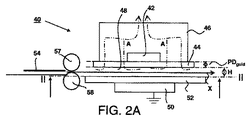
図2Aは、本発明の一実施形態に係るコロナ処理装置の側面図を示す。シート搬送手段は、搬送経路48を介して、コロナユニット40に沿った矢印Xで示す方向にカットシート材54を搬送する。搬送経路48の高さHは、搬送するカットシート材の厚さに十分対応した高さである。なお、図2Aに搬送経路の高さHを概略的に示したが、高さHは一般的に1〜3mmの範囲にある。シート搬送手段は駆動ローラー58及び自由回転ローラー57を含み、駆動ローラー58及び自由回転ローラー57は共に搬送ピンチを形成する。コロナユニット40は、本体部46と、1つのコロナ電極42を含むコロナ手段と、複数のシートガイド要素44(図2B参照)とを含む。複数のシートガイド要素44はコロナ電極42と搬送経路48との間に位置している。複数のシートガイド要素44のそれぞれは、搬送経路48とコロナ電極42との間に所定の距離PDguidをもたらす。図2Aの所定の距離PDguidは概略的に示したものであるが、該距離は一般に約1.5mmの範囲にある。シートガイド要素44は、酸化アルミニウム(Al2O3)、窒化ケイ素(Si3N4)又は炭化ケイ素(SiC)等のセラミック材料で構成され得る。コロナユニットは対極50をさらに含む。対極50は電気的に接地されている。また、シート搬送手段は、コロナ電極42に沿ったシート搬送経路48の方向にシート54を搬送する間に、シート54を支持するためのシート支持面52を含む。
FIG. 2A shows a side view of a corona treatment apparatus according to one embodiment of the present invention. The sheet conveying means conveys the
矢印Aで示す空気の流れがコロナユニット40の内部で供給される。空気の流れは、コロナ電極42と対極50との間で生じる空気汚染物質(air contaminations)を除去し、その汚染物質を空気ポンプ装置(図示せず)の方に向ける。空気ポンプ装置は、空気の流れからオゾン等の空気汚染物質を除去するためにフィルタをさらに含む。
An air flow indicated by an arrow A is supplied inside the
他の実施形態では、シート支持面52は、ガラス層又はポリマー層等のセラミック層といった電気絶縁層を含む。対極50と搬送経路48との間に配置された電気絶縁層は、コロナ手段42がカットシート材54の表面に対してコロナ放電工程を行う間のカットシート材の表面処理がある程度広がるようにする。これはカットシート材54の表面処理の均一性及び品質を改善する。
In other embodiments, the
図2Bは、図2Aに示す実施形態のコロナ処理装置の線II−IIに沿った底面図を示す。コロナ電極42は所定の幅Wcorona及び長さLcoronaを有し、それらに亘ってコロナプラズマ処理が適用される。本実施形態のコロナ電極のコロナプラズマ処理長は、コロナ電極のシート搬送方向Xの寸法Lcoronaと同じである。
FIG. 2B shows a bottom view along line II-II of the corona treatment apparatus of the embodiment shown in FIG. 2A. The
シートガイド要素44は、コロナユニット40に沿って、矢印Xで示す方向にカットシート材をガイドする。複数のシートガイド要素44のそれぞれは、シート搬送方向Xに対してαで示す角度で配置された方向に伸びている。シートガイド要素は、コロナ電極42がシートガイド要素で覆われる領域でのカットシート材の表面処理を妨げるか又は軽減する。複数のガイド要素間の距離はdguidである。一実施形態では、距離dguidは、コロナ電極42の処理長Lcoronaに亘ってコロナユニット4に沿った方向Xにカットシートを移動する場合に、カットシートの表面の一部が複数のガイド要素44のうちの多くて1つと接触するような距離である。
The
図3は、本発明に係るコロナ処理装置のシートガイド要素の角度の拡大底面図を示す。シートガイド要素44は所定の幅Wguidを有し、シート搬送方向Xに対してαで示す角度で配置されている。コロナ電極42は、カットシート材の表面の特定部分にコロナプラズマ処理を施すことが可能な処理長Lcoronaを有する。点Sで示すカットシート材の表面の一部が矢印Xの軌道をたどる場合、シートガイド要素44がコロナ電極42の長さLnon−treatに沿った領域を覆っているため、表面の前記部分は同領域ではコロナ処理を受けないが、長さLtreatに沿った領域にはシートガイド要素が存在しないため同領域ではコロナ処理を受ける。角度αは、コロナ電極の処理長の最大で20%がシートガイド要素44に覆われるように選択される。シートガイド要素44の幅Wguidが増加するか又はコロナ電極42の処理長Lcoronaが減少した場合、角度αを増やして十分な表面処理が確実になるようにしてもよい。角度αの下限値α(最小)とシートガイド要素44の幅Wguid及びコロナ電極42の処理長Lcoronaの関係は、下記関数により表される。
FIG. 3 shows an enlarged bottom view of the angle of the sheet guide element of the corona treatment device according to the present invention.
sin α(最小)=(Wguid/Lnon−treat)=(Wguid/0.2×Lcorona)
角度αは少なくともα(最小)以上になるように選択される。
sin α (minimum) = (W guid / L non -treat) = (W guid /0.2×L corona)
The angle α is selected to be at least α (minimum) or more.
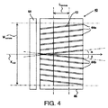
図4は、コロナ処理装置の他の実施形態の底面図を示す。複数のシートガイド要素のサブセット44a及び複数のシートガイド要素のサブセット44bは、コロナユニット40に沿って矢印Xで示す方向にカットシート材をガイドする。矢印Xmidで示す線の一方側の複数のガイド要素のサブセット44aは、シート搬送方向Xに対してαで示す角度で配置されている。矢印Xmidで示す線の他方側の複数のガイド要素のサブセット44bは、シート搬送方向Xに対してβで示す角度で配置されている。カットシートは方向Xに沿って搬送される。カットシートは、矢印Xmidで示す線の対向側でカットシートの側端が移動するように搬送され得る。その結果、カットシートの2つの側端の双方は、カットシートの搬送を妨げることなくガイドされる。
FIG. 4 shows a bottom view of another embodiment of the corona treatment apparatus. The plurality of sheet
特定の実施形態では、各カットシートの表面の中央部が、矢印Xmidで示す線の位置で移動される。その結果、カットシート材の2つの側端は、カットシート材の幅とは無関係に矢印Xmidのいずれかの側に位置する。複数のガイド要素のサブセット44a及び44bは、複数のガイド要素のそれぞれが、搬送されているシートの方向において、該シートの各側端から離れる方を向くような形で線Xmidの両側に配置されている。その結果、シートの角又は側端によってシートの搬送が妨げられることなく、任意の幅のカットシート材をコロナ電極42に沿って容易にガイドできる。
In a specific embodiment, the center part of the surface of each cut sheet is moved at the position of the line indicated by the arrow Xmid . As a result, the two side edges of the cut sheet material are located on either side of the arrow X mid regardless of the width of the cut sheet material. The plurality of
図5Aは本発明の一実施形態に係るコロナ処理装置の側面図を示す。コロナユニット40は、シート搬送経路48に沿って、互いに相対距離で配置された4つのコロナ電極42a、42b、42c、42dを含む。コロナ電極42a、42b、42c、42dは、Aで示す矢印が表す空気の流れがコロナユニット40の内部で容易に流れることができるように配置されている。空気の流れは、複数のコロナ電極42a、42b、42c、42dと対極50との間で生じる空気汚染物質を除去し、その汚染物質を空気ポンプ装置(図示せず)の方に向ける。
FIG. 5A shows a side view of a corona treatment apparatus according to an embodiment of the present invention. The
図5Bは、図5Aに示す実施形態のコロナ処理装置の線II−IIに沿った底面図を示す。複数のシートガイド要素のサブセット44a及び複数のシートガイド要素のサブセット44bは、コロナユニット40に沿って、矢印Xで示す方向にカットシート材をガイドする。複数のガイド要素のサブセット44aは、シート搬送方向Xに対してαで示す角度で配置されている。複数のガイド要素のサブセット44bは、シート搬送方向Xに対してβで示す角度で配置されている。コロナ電極42a、42b、42c、42dは長さLx(a)、Lx(b)、Lx(c)、Lx(d)をそれぞれ有し、その長さに亘ってカットシート材の表面の一部にコロナプラズマ処理が施される。コロナ電極42a、42b、42c、42dの処理長は同じであってもよいし異なってもよい。複数のコロナ電極42a、42b、42c、42dは、長さL’coronaに亘ってシート搬送方向Xに配置されている。コロナプラズマ処理長の合計は、コロナ電極42a、42b、42c、42dのそれぞれの長さLx(a)、Lx(b)、Lx(c)、Lx(d)の合計である。
FIG. 5B shows a bottom view along line II-II of the corona treatment apparatus of the embodiment shown in FIG. 5A. The plurality of sheet
隣り合うシートガイド要素間の距離dguidは、4つのコロナ電極42a、42b、42c、42dの長さL’coronaに亘ってコロナユニット40に沿ったX方向に移動する場合に、カットシートの表面の一部が複数のガイド要素44のうちの多くて1つと接触するような距離である。角度α及びβは、複数のコロナ電極42a、42b、42c、42dの長さLx(a)、Lx(b)、Lx(c)、Lx(d)の合計の最大で20%がシートガイド要素44に覆われるように選択される。シートガイド要素44の幅Wguidが増加するか又は複数のコロナ電極42a、42b、42c、42dの長さLx(a)、Lx(b)、Lx(c)、Lx(d)の合計が減少した場合、角度α及びβを増やして十分な表面処理が確実になるようにしてもよい。
The distance dguid between adjacent sheet guide elements is the surface of the cut sheet when moving in the X direction along the
図6Aは、本発明の一実施形態に係るコロナ処理装置の側面図を示す。コロナユニット40は4つのコロナ電極42a、42b、42c、42dと、複数のシートガイド要素44(図6Bに図示)と、3つの支持要素62a、62b及び62cとを含む。支持要素62a、62b及び62cは、4つのコロナ電極42a、42b、42c、42dの間で、コロナ電極42a、42b、42c、42dと略平行に配置されている。支持要素62a、62b及び62cは複数のシートガイド要素44に接続されている。これによって、比較的簡素で機械的に強固なグリッド構造がもたらされる。支持要素62a、62b、62cへの接続によって、複数のシートガイド要素44の各支持位置の間に比較的短い長さdsupportがもたらされるため、長さdsupportに垂直な方向において、シートガイド要素44に比較的高い剛性がもたらされる。この実施形態では、シートガイド要素44は、所定の距離PDguidよりも小さくなるように調整される高さHguidを有しており、コロナ電極42a、42b、42c、42dから所定の距離で配置されている。これは、コロナ電極42a、42b、42c、42dによって生成される電場にシートガイド要素44があまり晒されないという利点がある。シートガイド要素44は支持されているため、例えば、シートガイド要素44に沿った搬送の間にカットシート材54と接触する時でも、コロナ電極42a、42b、42c、42dと搬送経路48との間の所定の距離PDguidが正確に維持される。少なくとも1つの支持要素62a、62b、62cは、接続要素64a、64b(図6Bに示す)により互いに接続されている。接続要素64a、64bは本体部46に固定されている。
FIG. 6A shows a side view of a corona treatment device according to one embodiment of the present invention. The
図6Bは、図6Aに示す実施形態のコロナ処理装置の線II−IIに沿った底面図を示す。複数のシートガイド要素のサブセット44a及び複数のシートガイド要素のサブセット44bは、コロナユニット40に沿って、矢印Xで示す方向にカットシート材をガイドする。複数のガイド要素のサブセット44aは、シート搬送方向Xに対してαで示す角度で配置されている。複数のガイド要素のサブセット44bは、シート搬送方向Xに対してβで示す角度で配置されている。
FIG. 6B shows a bottom view along line II-II of the corona treatment apparatus of the embodiment shown in FIG. 6A. The plurality of sheet
図7は、本発明の一実施形態に係る、シートの一部をシート支持面に押し付けるための押さえフットを含むシート搬送手段の側面図である。シート搬送手段は、コロナユニット40に沿った矢印Xで示す方向にカットシート材54を搬送する。シート搬送手段は駆動ローラー58及び自由回転ローラー57を含み、駆動ローラー58及び自由回転ローラー57は共に搬送ピンチを形成する。押さえフット74は、クランプ76によって自由回転ローラー57の軸70に固定されている。押さえフット74の下流側に重り72が設けられているため、矢印Fで示す圧力がシート搬送経路48の近傍でシート支持面52にかかる。コロナ装置40からオゾンガス等の空気汚染物質を除去するために、矢印Aで表す空気の流れが搬送経路の内部で供給される。押さえフット74は、シート搬送方向Xに垂直な方向において、シート54に剛性を提供する。これは、搬送経路48の内部で空気の流れが提供されていても、コロナユニット40に沿ったシート54の搬送方向に亘る制御の改善を可能にする。
FIG. 7 is a side view of the sheet conveying unit including a pressing foot for pressing a part of the sheet against the sheet supporting surface according to the embodiment of the present invention. The sheet conveying means conveys the
図8Aは、本発明の一実施形態に係るシートガイド要素の構造の拡大側面図を示す。シートガイド要素44は3つの突起部84a、84b及び84cを含む。突起部は孔85a、85b及び85cをそれぞれ含む。孔85a、85b及び85cのそれぞれは、コロナ電極42(図示せず)を受け入れるのに好適な空間を提供し得る。突起部84a、84b及び84cが、孔85a、85b及び85cの少なくとも一方側でコロナ電極42に固定されている場合、コロナ電極42はシートガイド要素44のための支持要素を提供する。シートガイド要素44は、酸化アルミニウム(Al2O3)、窒化ケイ素(Si3N4)又は炭化ケイ素(SiC)等のセラミック材料で構成されている。特定の実施形態では、コロナ電極42の高さは、孔85a〜85eの高さと実質的に同じである。シートガイド要素44により良好な機械特性を提供するために、2つの突起部84a、84bの間の距離dpが調整され得る。一実施形態では、距離dpは0であり得る。そのため、突起部84a、84bは、2つの孔85a、85bを含む1つの突起部の要素であり得る。
FIG. 8A shows an enlarged side view of the structure of the seat guide element according to one embodiment of the present invention. The
孔85a、85b、85cは、延在するシートガイド要素の上側44’と揃っていてもよいし(孔85a、85c)、延在するシートガイド要素の上側44’に対してオフセットされていてもよい(孔85b)。前記孔は長方形状であり得るが、他の任意の形状を有していてもよい。コロナ電極42と紙搬送経路48、即ち、シートガイド要素の下側44’’との間の所定の距離PDguid、は、コロナ電極42の下側がシートガイド要素44の上側44’と揃っている場合、上側44’と揃っている。あるいは、コロナ電極の下側をシートガイド要素44の上側44’からオフセットした状態で配置して所定の距離(図示せず)を調整するようにしてもよい。
The
図8Bは、本発明の一実施形態に係るコロナ処理装置の構造の側面図を示す。シート搬送手段は、コロナユニット40に沿って、矢印Xで示すシート搬送経路の方向にカットシート材を搬送する。シート搬送手段は駆動ローラー58及び自由回転ローラー57を含み、駆動ローラー58及び自由回転ローラー57は共に搬送ピンチを形成する。押さえフット74は、クランプ76によって自由回転ローラー57の軸に固定されている。押さえフットの下流側に重り72が設けられているため、圧力がシート搬送経路の近傍でシート支持面50にかかる。コロナ装置40からオゾンガス等の空気汚染物質を除去するために、搬送経路の内部で空気の流れ(図示せず)が供給される。
FIG. 8B shows a side view of the structure of the corona treatment apparatus according to one embodiment of the present invention. The sheet conveying means conveys the cut sheet material along the
コロナユニット40は、本体部46と、5つのコロナ電極42a、42b、42c、42d、42e(図8cに図示)と、それぞれが突起部84を含む複数のシートガイド要素44(図8cに図示)とを含む。突起部84は5つの孔85a〜85eを含む。5つの孔のそれぞれはコロナ電極42a〜42e(図8Cに図示)を受け入れる。本体部46は、複数のシートガイド要素44を保持する2つの本体部要素82を含む。2つの本体部要素82はコロナ電極42a〜42eと平行な方向に延在しており、それらは共に電気絶縁性である。シートガイド要素44は、コロナ電極42a〜42eと搬送経路との間に、一般に約1.5mmの範囲の所定の距離PDguid(図示せず)をもたらす。シートガイド要素44は、酸化アルミニウム(Al2O3)、窒化ケイ素(Si3N4)又は炭化ケイ素(SiC)等のセラミック材料で構成されている。
The
孔85a〜85eは、シートガイド要素の上側44’からオフセットされた状態で配置されている。孔85a〜85eとシートガイド要素の下側44’’との間のシートガイド要素44の部分の高さは、シートガイド要素44の他の部分の高さよりも小さい。シートガイド要素44は、突起部84の孔85a〜85eのそれぞれの少なくとも一方側により5つのコロナ電極42のそれぞれに接続されている。5つのコロナ電極42のぞれぞれの高さは、対応する孔85a〜85eの高さと同じであることが好ましい。突起部84は、コロナ電極42a〜42eへの接続と共に、シートガイド要素の長さに垂直な方向において、シートガイド要素44に比較的高い剛性をもたらす。その結果、例えば、シートガイド要素44に沿った搬送の間にカットシート材と接触する時でも、コロナ電極42a〜42eと搬送経路との間の所定の距離が正確に維持される。シート支持面50は、電気的に接地され、故に対極としても機能するRVS板である。
The
図8Cは、図8Bに示す実施形態のコロナ処理装置の構造の線II−IIに沿った部分底面図を示す。本体部64は、複数のシートガイド要素44を保持するための2つの本体部要素82を含む。本体部46はさらに、コロナユニット40を扱うための取っ手86を各端部に含む。
FIG. 8C shows a partial bottom view along line II-II of the structure of the corona treatment device of the embodiment shown in FIG. 8B. The main body 64 includes two
ガイド要素44は、コロナユニット40に沿って、矢印Xで示す方向にカットシート材をガイドする。複数のガイド要素44のそれぞれは約1mmの幅Wguidを有し、シート搬送方向Xに対してαで示す角度で配置された方向に伸びている。
The
シートガイド要素は、コロナ電極42a〜42eがシートガイド要素で覆われた領域でのカットシート材の表面処理を妨げるか又は軽減する。本実施形態での各コロナ電極42a〜42eのコロナプラズマ処理長は10mmである。コロナプラズマ処理長Lcoronaの合計は50mmである。5つのコロナ電極42a〜42eの全長L’coronaが約55mmであることは、コロナプラズマ処理長の合計に、5つのコロナ電極の間の距離を加えることで求められ、この実施形態では、コロナプラズマ処理長Lcoronaと同じではない。
The sheet guide element prevents or reduces the surface treatment of the cut sheet material in the area where the
複数のシートガイド要素間の距離dguidは10mmである。隣り合うシートガイド要素間の距離dguidは、5つのコロナ電極42a〜42eの処理長L’coronaに亘ってコロナユニット40に沿った方向Xに移動する場合に、カットシートの表面の一部が複数のガイド要素44の多くて1つと接触するように選択される。
The distance d guid between a plurality of sheet guide element is 10 mm. The distance d guid between adjacent sheet guide element, when moving in the direction X along the
本実施形態の角度αは6〜10°の範囲で選択される。該角度の下限値は、シートガイド要素44の幅及びコロナ電極の処理長Lcoronaに対応する。該角度の上限値は、隣り合うシートガイド要素44間の距離dguid及び5つのコロナ電極42a〜42eの全長L’coronaに対応する。
The angle α in this embodiment is selected in the range of 6 to 10 °. The lower limit value of the angle corresponds to the width of the
図9Aは、本発明の一実施形態に係るコロナ処理装置の構造の側面図を示す。対極50を含む対極ユニット61は搬送経路48の下に設けられている。本実施形態では、対極50は軸59の周りを回転可能な円筒電極であり、対極50の外面に電気絶縁層60を含む。対極50は電気的に接地されている。電気絶縁層60は、コロナ要素42から対極50に向けられたコロナ放電処理工程がある程度広がるようにするため、シートの表面処理の品質が改善する。
FIG. 9A shows a side view of the structure of the corona treatment apparatus according to one embodiment of the present invention. A
対極は、軸59の周りをRの方向に回転される。対極50の表面を冷却するために、方向Cに空気が供給される。シート支持面52は、コロナユニット40に沿ってカットシート54を搬送する間にカットシート54を支持するために、対極50と搬送経路48との間に配置されている。
The counter electrode is rotated about
図9Bは、図9Aに示す実施形態のコロナ処理装置の線III−IIIに沿った底面図を示す。本実施形態のコロナ電極42の処理長は15mmであり、対極50の直径Dcounterは100mmである。シート支持面52は複数のシート支持要素92を含む。シート支持要素92は、シート搬送方向Xに対して角度γを持つ方向に伸びている。搬送経路48の下側のシート支持要素92は、搬送経路48の上側でのコロナ電極42によるカットシートの表面コロナプラズマ処理を妨げないため、角度γは0であり得る。あるいは、対極50に沿ったカットシートの下側の誘導を制御されたものにするために、角度γは0よりも大きい値が選択され得る。一実施形態では、シート支持要素が、例えばパーフルオロアルキレンポリマーを含むワイヤ等のワイヤで構成され得る。
9B shows a bottom view along line III-III of the corona treatment apparatus of the embodiment shown in FIG. 9A. The treatment length of the
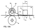
図10A及び図10Bは、シートガイド要素がシート搬送手段の押さえフットの一部である本発明の一実施形態を示す。図10Aは、シート54の一部をシート支持面52に押し付けるための押さえフット174を含むシート搬送手段の側面図を示す。シート搬送手段は、コロナユニット40に沿った矢印Xで示すシート搬送経路48の方向にカットシート材54を搬送する。シート搬送手段は駆動ローラー58及び自由回転ローラー57を含み、駆動ローラー58及び自由回転ローラー57は共に搬送ピンチを形成する。押さえフット174は、クランプ176により自由回転ローラー57の軸170に固定されている。押さえフット174は、コロナユニット40のコロナ電極42までシート搬送経路48の方向に伸びた第1の部位175を含む。押さえフット174は、コロナ電極42と搬送経路48との間で、コロナプラズマ処理長Lcoronaの少なくとも一部に亘って伸びた第2の部位178をさらに含む。
10A and 10B show an embodiment of the present invention in which the sheet guide element is part of the holding foot of the sheet conveying means. FIG. 10A shows a side view of the sheet conveying means including a
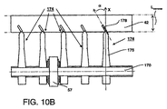
図10Bに、図10Aに示すシート搬送手段及び押さえフットの線II-IIに沿った底面図を示す。多くの押さえフット174が図示されている。押さえフット174のそれぞれは自由回転ローラー57の軸170に接続されている。押さえフット174の第1の部位175は、コロナユニット40のコロナ電極42まで、シート搬送経路48の搬送方向xに伸びている。押さえフット174の第2の部位178は、シート搬送経路48の搬送方向xに対して角度αで配置された方向に伸びている。角度αは、押さえフットの第2の部位178がコロナ電極42のコロナプラズマ処理長Lcoronaを部分的にのみ覆うように好適に選択される。押さえフットの第2の部位178が、コロナ電極42の搬送方向xのコロナプラズマ処理長Lcoronaを最大で20%覆うことが好ましい。その結果、コロナ電極42は、コロナ電極42の幅(即ち、搬送方向xに垂直に)に亘って均一且つ高品質なコロナプラズマ処理をカットシート媒体にもたらす。
FIG. 10B shows a bottom view along the line II-II of the sheet conveying means and the pressing foot shown in FIG. 10A. A number of
本発明の詳細な実施形態を本明細書で開示してきたが、開示した実施形態は、様々な形で実施可能な本発明の例示に過ぎないことが分かる。従って、本明細書で開示した具体的な構造及び機能についての詳細を限定的に解釈するのではなく、請求項の根拠として及び事実上適切な詳細構造の全てで本発明を様々な形で用いるのを当業者に教示するための例示的根拠として解釈すべきである。特に、別々の従属項で提示及び記載の特徴は組み合わせで適用され得る。そのような請求項の任意の有利な組み合わせがここに開示される。 Although detailed embodiments of the present invention have been disclosed herein, it is understood that the disclosed embodiments are merely illustrative of the invention that can be implemented in various forms. Accordingly, it is to be understood that the present invention may be employed in various forms as the basis for a claim and in any and all details that are reasonably pertinent, rather than being interpreted in a limiting sense as to the specific structures and functions disclosed herein. Should be construed as an exemplary basis for teaching those skilled in the art. In particular, features presented and described in separate dependent claims may be applied in combination. Any advantageous combinations of such claims are disclosed herein.
また、本明細書で使用の用語及び表現は限定を意図したものではなく、むしろ本発明の理解可能な説明を提供するために用いたものである。本明細書で使用の「a」又は「an」は1つ以上と定義される。本明細書で使用の複数という用語は2つ以上と定義される。本明細書で使用の他のという用語は、少なくとも第2以上と定義される。本明細書で使用の含有する及び/又は有するという用語は、含む(即ち、オープンランゲージ)を意味すると定義される。本明細書で使用の連結されたという用語は、必ずしも直接的ではないが接続されていること意味するものと定義される。 Also, the terms and expressions used herein are not intended to be limiting, but rather are used to provide an understandable description of the invention. As used herein, “a” or “an” is defined as one or more. As used herein, the term plural is defined as two or more. The term other as used herein is defined as at least a second or more. As used herein, the terms containing and / or having are defined to mean including (ie, open language). The term linked as used herein is defined to mean connected, although not necessarily directly.
本発明を説明してきたが、本発明は多くの方法で変更され得ることが明らかである。そのような変更は本発明の精神及び範囲からの逸脱と見做すべきではなく、そのような変更の全ては、当業者には明らかなように下記の請求項の範囲に含まれる。 Having described the invention, it should be apparent that the invention can be modified in many ways. Such modifications are not to be regarded as a departure from the spirit and scope of the invention, and all such modifications are within the scope of the following claims, as will be apparent to those skilled in the art.
下記の詳細な説明及び添付の図面から本発明がより完全に分かるようになる。下記の詳細な説明及び添付の図面は説明を目的としたものに過ぎないため、本発明を限定しない。
Claims (15)
当該コロナ処理装置は:
コロナ電極を含み、シートの表面にコロナ処理を施すためのコロナ手段;
前記コロナ手段に沿った搬送経路の方向に、前記シートを搬送するためのシート搬送手段;及び
前記コロナ手段に沿って前記シートをガイドするための複数のシートガイド要素;
を含み、
前記複数のシートガイド要素が前記コロナ電極と前記搬送経路との間に位置しているため、前記搬送経路と前記コロナ電極との間に所定の距離がもたらされ、前記複数のシートガイド要素は、シート搬送方向に対して第1の角度の方向に伸びた第1のシートガイド要素を少なくとも含む、コロナ処理装置。 A corona treatment device for treating cut sheet material,
The corona treatment equipment is:
Corona means including a corona electrode and for applying a corona treatment to the surface of the sheet;
Sheet conveying means for conveying the sheet in the direction of the conveying path along the corona means; and a plurality of sheet guide elements for guiding the sheet along the corona means;
Including
Since the plurality of sheet guide elements are located between the corona electrode and the conveyance path, a predetermined distance is provided between the conveyance path and the corona electrode, and the plurality of sheet guide elements are A corona treatment device comprising at least a first sheet guide element extending in a direction at a first angle with respect to the sheet conveying direction.
前記カットシート材の表面を処理するための請求項1〜14のいずれか1項に記載のコロナ処理装置;
前記カットシート材にマーキング材料を適用するための少なくとも1つのマーキングステーション;
カットシート供給ステーション;及び
カットシート配送ステーション;
を含む印刷システム。
A printing system for processing cut sheet material,
The corona treatment apparatus of any one of Claims 1-14 for processing the surface of the said cut sheet material;
At least one marking station for applying a marking material to the cut sheet material;
Cut sheet supply station; and cut sheet delivery station;
Including printing system.
Applications Claiming Priority (3)
| Application Number | Priority Date | Filing Date | Title |
|---|---|---|---|
| EP12151049 | 2012-01-13 | ||
| EP12151049.9 | 2012-01-13 | ||
| PCT/EP2013/050483 WO2013104753A2 (en) | 2012-01-13 | 2013-01-11 | Corona treatment device |
Publications (2)
| Publication Number | Publication Date |
|---|---|
| JP2015510458A true JP2015510458A (en) | 2015-04-09 |
| JP2015510458A5 JP2015510458A5 (en) | 2016-02-18 |
Family
ID=47563495
Family Applications (1)
| Application Number | Title | Priority Date | Filing Date |
|---|---|---|---|
| JP2014551626A Withdrawn JP2015510458A (en) | 2012-01-13 | 2013-01-11 | Corona treatment device |
Country Status (4)
| Country | Link |
|---|---|
| US (1) | US20140320575A1 (en) |
| EP (1) | EP2802455B1 (en) |
| JP (1) | JP2015510458A (en) |
| WO (1) | WO2013104753A2 (en) |
Cited By (3)
| Publication number | Priority date | Publication date | Assignee | Title |
|---|---|---|---|---|
| JP2018099871A (en) * | 2016-11-18 | 2018-06-28 | イマジニアリング株式会社 | Printer |
| JP2020011460A (en) * | 2018-07-19 | 2020-01-23 | サカタインクス株式会社 | Plasma treatment inkjet printing device |
| WO2023074632A1 (en) * | 2021-10-29 | 2023-05-04 | 株式会社デュプロ | Discharge processing apparatus and sheet material processing system |
Families Citing this family (6)
| Publication number | Priority date | Publication date | Assignee | Title |
|---|---|---|---|---|
| DK177766B3 (en) | 2013-03-19 | 2018-04-30 | Tresu As | Device and method of corona treatment |
| JP2015085527A (en) * | 2013-10-28 | 2015-05-07 | 株式会社リコー | Reforming device, image formation device, image formation system, and manufacturing method for print material |
| EP3129230B1 (en) | 2014-04-11 | 2018-02-28 | OCE-Technologies B.V. | Inkjet printer comprising a plasma generation device, plasma generation device for the same, and relative methods |
| EP3025991B1 (en) | 2014-11-27 | 2017-07-26 | OCE-Technologies B.V. | Method and sheet transport assembly for transferring a sheet between two conveyors |
| DE102016109044B3 (en) | 2016-05-17 | 2017-07-06 | Leonhard Kurz Stiftung & Co. Kg | Device for surface treatment of a substrate |
| CN115847795B (en) * | 2022-12-30 | 2023-09-15 | 常州奥福电子设备有限公司 | Film corona machine with uniform corona gap |
Family Cites Families (5)
| Publication number | Priority date | Publication date | Assignee | Title |
|---|---|---|---|---|
| JPH0617127Y2 (en) * | 1987-11-25 | 1994-05-02 | 三田工業株式会社 | Corona discharger |
| US5527123A (en) * | 1995-02-28 | 1996-06-18 | Hewlett-Packard Company | Media handling in an ink-jet printer |
| DE10050301B4 (en) * | 2000-10-10 | 2004-05-13 | Windmöller & Hölscher | Process for removing a gaseous laminar boundary layer from high-speed material |
| US6941606B2 (en) * | 2002-07-02 | 2005-09-13 | Electrostatics, Incorporated | Sheet and web cleaner on suction hood |
| JP2009279796A (en) * | 2008-05-20 | 2009-12-03 | Tohoku Ricoh Co Ltd | Inkjet recording method and inkjet recording device |
-
2013
- 2013-01-11 WO PCT/EP2013/050483 patent/WO2013104753A2/en active Application Filing
- 2013-01-11 EP EP13700552.6A patent/EP2802455B1/en active Active
- 2013-01-11 JP JP2014551626A patent/JP2015510458A/en not_active Withdrawn
-
2014
- 2014-07-11 US US14/329,724 patent/US20140320575A1/en not_active Abandoned
Cited By (4)
| Publication number | Priority date | Publication date | Assignee | Title |
|---|---|---|---|---|
| JP2018099871A (en) * | 2016-11-18 | 2018-06-28 | イマジニアリング株式会社 | Printer |
| JP2020011460A (en) * | 2018-07-19 | 2020-01-23 | サカタインクス株式会社 | Plasma treatment inkjet printing device |
| JP7110018B2 (en) | 2018-07-19 | 2022-08-01 | サカタインクス株式会社 | Plasma processing inkjet printer |
| WO2023074632A1 (en) * | 2021-10-29 | 2023-05-04 | 株式会社デュプロ | Discharge processing apparatus and sheet material processing system |
Also Published As
| Publication number | Publication date |
|---|---|
| WO2013104753A2 (en) | 2013-07-18 |
| WO2013104753A3 (en) | 2013-11-21 |
| US20140320575A1 (en) | 2014-10-30 |
| EP2802455B1 (en) | 2016-04-27 |
| EP2802455A2 (en) | 2014-11-19 |
Similar Documents
| Publication | Publication Date | Title |
|---|---|---|
| JP2015510458A (en) | Corona treatment device | |
| US8157369B2 (en) | Media hold-down system having cross process chambering | |
| JP6375868B2 (en) | Image forming apparatus, image forming system, and printed matter production method | |
| US8628188B2 (en) | Drying apparatus and printing apparatus | |
| JP6435896B2 (en) | Processed material reforming apparatus, printing apparatus, printing system, and printed material manufacturing method | |
| JP2018066552A (en) | Dryer and printer | |
| JP6476939B2 (en) | Processed material reforming apparatus, printing apparatus, printing system, and printed material manufacturing method | |
| WO2011064226A1 (en) | Sheet processing device | |
| JP6451129B2 (en) | Plasma processing apparatus, printing apparatus, printing system, and printed matter manufacturing method | |
| US8408270B2 (en) | Apparatuses useful in printing, fixing devices and methods of stripping substrates from surfaces in apparatuses useful in printing | |
| JP2017223384A (en) | Dryer and liquid fixation device | |
| JP6221211B2 (en) | Dielectric barrier discharge generator, sheet material reforming apparatus, image forming apparatus, and printed matter production method | |
| US10723152B2 (en) | Electric field generating transport member | |
| JP2004334176A (en) | Apparatus and method for handling material to be printed within microwave device | |
| US6997549B2 (en) | Media hold down system | |
| US8840105B1 (en) | Recharger to restore electrostatic holding force | |
| US9776431B2 (en) | Medium conveying device and image recording apparatus | |
| US20150036155A1 (en) | Charger providing non-uniform electrostatic holding force | |
| US8844926B1 (en) | Controlling recharging to restore electrostatic holding force | |
| JP7353230B2 (en) | Systems and devices for attenuating curl on substrates printed by inkjet printers | |
| JP2007331239A (en) | Liquid droplet discharger | |
| US9809039B2 (en) | Plasma generating device | |
| US10493777B1 (en) | Electric field generating transport member | |
| US11318773B2 (en) | Printing apparatus and method for manufacturing printed matter | |
| JP7143765B2 (en) | Recording medium processing device and image recording device |
Legal Events
| Date | Code | Title | Description |
|---|---|---|---|
| A521 | Request for written amendment filed |
Free format text: JAPANESE INTERMEDIATE CODE: A523 Effective date: 20151222 |
|
| A621 | Written request for application examination |
Free format text: JAPANESE INTERMEDIATE CODE: A621 Effective date: 20151222 |
|
| A761 | Written withdrawal of application |
Free format text: JAPANESE INTERMEDIATE CODE: A761 Effective date: 20160901 |