US9853220B2 - Efficient organic light-emitting diodes and fabrication of the same - Google Patents
Efficient organic light-emitting diodes and fabrication of the same Download PDFInfo
- Publication number
- US9853220B2 US9853220B2 US14/344,300 US201214344300A US9853220B2 US 9853220 B2 US9853220 B2 US 9853220B2 US 201214344300 A US201214344300 A US 201214344300A US 9853220 B2 US9853220 B2 US 9853220B2
- Authority
- US
- United States
- Prior art keywords
- light
- layer
- emitting layer
- phosphorescent
- emitting
- Prior art date
- Legal status (The legal status is an assumption and is not a legal conclusion. Google has not performed a legal analysis and makes no representation as to the accuracy of the status listed.)
- Active, expires
Links
- 238000004519 manufacturing process Methods 0.000 title description 2
- 230000005525 hole transport Effects 0.000 claims abstract description 54
- 238000000149 argon plasma sintering Methods 0.000 claims abstract description 33
- 238000002347 injection Methods 0.000 claims abstract description 26
- 239000007924 injection Substances 0.000 claims abstract description 26
- 239000000758 substrate Substances 0.000 claims abstract description 21
- 239000000463 material Substances 0.000 claims description 98
- 239000002019 doping agent Substances 0.000 claims description 26
- JKQOBWVOAYFWKG-UHFFFAOYSA-N molybdenum trioxide Chemical compound O=[Mo](=O)=O JKQOBWVOAYFWKG-UHFFFAOYSA-N 0.000 claims description 26
- UHOVQNZJYSORNB-UHFFFAOYSA-N Benzene Chemical compound C1=CC=CC=C1 UHOVQNZJYSORNB-UHFFFAOYSA-N 0.000 claims description 16
- 150000001875 compounds Chemical class 0.000 claims description 14
- 229910045601 alloy Inorganic materials 0.000 claims description 12
- 239000000956 alloy Substances 0.000 claims description 12
- 229910052749 magnesium Inorganic materials 0.000 claims description 11
- 229910052782 aluminium Inorganic materials 0.000 claims description 10
- 229910052709 silver Inorganic materials 0.000 claims description 8
- 229910052791 calcium Inorganic materials 0.000 claims description 7
- 229910052737 gold Inorganic materials 0.000 claims description 7
- IBHBKWKFFTZAHE-UHFFFAOYSA-N n-[4-[4-(n-naphthalen-1-ylanilino)phenyl]phenyl]-n-phenylnaphthalen-1-amine Chemical group C1=CC=CC=C1N(C=1C2=CC=CC=C2C=CC=1)C1=CC=C(C=2C=CC(=CC=2)N(C=2C=CC=CC=2)C=2C3=CC=CC=C3C=CC=2)C=C1 IBHBKWKFFTZAHE-UHFFFAOYSA-N 0.000 claims description 7
- 239000012780 transparent material Substances 0.000 claims description 7
- 239000007983 Tris buffer Substances 0.000 claims description 6
- 229910052802 copper Inorganic materials 0.000 claims description 3
- 229910052759 nickel Inorganic materials 0.000 claims description 2
- 239000010410 layer Substances 0.000 description 304
- 229910052751 metal Inorganic materials 0.000 description 19
- 239000002184 metal Substances 0.000 description 19
- 238000000151 deposition Methods 0.000 description 14
- 150000002739 metals Chemical class 0.000 description 13
- 230000008021 deposition Effects 0.000 description 12
- -1 rare earth elements Chemical class 0.000 description 11
- STTGYIUESPWXOW-UHFFFAOYSA-N 2,9-dimethyl-4,7-diphenyl-1,10-phenanthroline Chemical compound C=12C=CC3=C(C=4C=CC=CC=4)C=C(C)N=C3C2=NC(C)=CC=1C1=CC=CC=C1 STTGYIUESPWXOW-UHFFFAOYSA-N 0.000 description 9
- 239000011575 calcium Substances 0.000 description 9
- 239000011777 magnesium Substances 0.000 description 8
- XOLBLPGZBRYERU-UHFFFAOYSA-N tin dioxide Chemical compound O=[Sn]=O XOLBLPGZBRYERU-UHFFFAOYSA-N 0.000 description 8
- GEQBRULPNIVQPP-UHFFFAOYSA-N 2-[3,5-bis(1-phenylbenzimidazol-2-yl)phenyl]-1-phenylbenzimidazole Chemical compound C1=CC=CC=C1N1C2=CC=CC=C2N=C1C1=CC(C=2N(C3=CC=CC=C3N=2)C=2C=CC=CC=2)=CC(C=2N(C3=CC=CC=C3N=2)C=2C=CC=CC=2)=C1 GEQBRULPNIVQPP-UHFFFAOYSA-N 0.000 description 6
- 239000002245 particle Substances 0.000 description 6
- OKTJSMMVPCPJKN-UHFFFAOYSA-N Carbon Chemical compound [C] OKTJSMMVPCPJKN-UHFFFAOYSA-N 0.000 description 5
- 238000010438 heat treatment Methods 0.000 description 5
- VFUDMQLBKNMONU-UHFFFAOYSA-N 9-[4-(4-carbazol-9-ylphenyl)phenyl]carbazole Chemical group C12=CC=CC=C2C2=CC=CC=C2N1C1=CC=C(C=2C=CC(=CC=2)N2C3=CC=CC=C3C3=CC=CC=C32)C=C1 VFUDMQLBKNMONU-UHFFFAOYSA-N 0.000 description 4
- 239000002041 carbon nanotube Substances 0.000 description 4
- 229910021393 carbon nanotube Inorganic materials 0.000 description 4
- 238000001194 electroluminescence spectrum Methods 0.000 description 4
- 229910044991 metal oxide Inorganic materials 0.000 description 4
- 150000004706 metal oxides Chemical class 0.000 description 4
- 239000000203 mixture Substances 0.000 description 4
- 238000002834 transmittance Methods 0.000 description 4
- OYPRJOBELJOOCE-UHFFFAOYSA-N Calcium Chemical compound [Ca] OYPRJOBELJOOCE-UHFFFAOYSA-N 0.000 description 3
- FYYHWMGAXLPEAU-UHFFFAOYSA-N Magnesium Chemical compound [Mg] FYYHWMGAXLPEAU-UHFFFAOYSA-N 0.000 description 3
- 229910052772 Samarium Inorganic materials 0.000 description 3
- 229910052768 actinide Inorganic materials 0.000 description 3
- 150000001255 actinides Chemical class 0.000 description 3
- 229910052783 alkali metal Inorganic materials 0.000 description 3
- 150000001340 alkali metals Chemical class 0.000 description 3
- XAGFODPZIPBFFR-UHFFFAOYSA-N aluminium Chemical compound [Al] XAGFODPZIPBFFR-UHFFFAOYSA-N 0.000 description 3
- 229910052788 barium Inorganic materials 0.000 description 3
- DSAJWYNOEDNPEQ-UHFFFAOYSA-N barium atom Chemical compound [Ba] DSAJWYNOEDNPEQ-UHFFFAOYSA-N 0.000 description 3
- XZCJVWCMJYNSQO-UHFFFAOYSA-N butyl pbd Chemical compound C1=CC(C(C)(C)C)=CC=C1C1=NN=C(C=2C=CC(=CC=2)C=2C=CC=CC=2)O1 XZCJVWCMJYNSQO-UHFFFAOYSA-N 0.000 description 3
- 229940125782 compound 2 Drugs 0.000 description 3
- 239000011521 glass Substances 0.000 description 3
- 229910052738 indium Inorganic materials 0.000 description 3
- APFVFJFRJDLVQX-UHFFFAOYSA-N indium atom Chemical compound [In] APFVFJFRJDLVQX-UHFFFAOYSA-N 0.000 description 3
- 229910052747 lanthanoid Inorganic materials 0.000 description 3
- 150000002602 lanthanoids Chemical class 0.000 description 3
- 229920003227 poly(N-vinyl carbazole) Polymers 0.000 description 3
- 229910052761 rare earth metal Inorganic materials 0.000 description 3
- KZUNJOHGWZRPMI-UHFFFAOYSA-N samarium atom Chemical compound [Sm] KZUNJOHGWZRPMI-UHFFFAOYSA-N 0.000 description 3
- TVIVIEFSHFOWTE-UHFFFAOYSA-K tri(quinolin-8-yloxy)alumane Chemical compound [Al+3].C1=CN=C2C([O-])=CC=CC2=C1.C1=CN=C2C([O-])=CC=CC2=C1.C1=CN=C2C([O-])=CC=CC2=C1 TVIVIEFSHFOWTE-UHFFFAOYSA-K 0.000 description 3
- ODHXBMXNKOYIBV-UHFFFAOYSA-N triphenylamine Chemical compound C1=CC=CC=C1N(C=1C=CC=CC=1)C1=CC=CC=C1 ODHXBMXNKOYIBV-UHFFFAOYSA-N 0.000 description 3
- 238000001429 visible spectrum Methods 0.000 description 3
- 239000011800 void material Substances 0.000 description 3
- WXDXMXYEAGYOKI-UHFFFAOYSA-N 2-(6-pyridin-2-ylpyridin-2-yl)-5-[3-[5-(6-pyridin-2-ylpyridin-2-yl)-1,3,4-oxadiazol-2-yl]phenyl]-1,3,4-oxadiazole Chemical compound N1=CC=CC=C1C1=CC=CC(C=2OC(=NN=2)C=2C=C(C=CC=2)C=2OC(=NN=2)C=2N=C(C=CC=2)C=2N=CC=CC=2)=N1 WXDXMXYEAGYOKI-UHFFFAOYSA-N 0.000 description 2
- AWXGSYPUMWKTBR-UHFFFAOYSA-N 4-carbazol-9-yl-n,n-bis(4-carbazol-9-ylphenyl)aniline Chemical compound C12=CC=CC=C2C2=CC=CC=C2N1C1=CC=C(N(C=2C=CC(=CC=2)N2C3=CC=CC=C3C3=CC=CC=C32)C=2C=CC(=CC=2)N2C3=CC=CC=C3C3=CC=CC=C32)C=C1 AWXGSYPUMWKTBR-UHFFFAOYSA-N 0.000 description 2
- UJOBWOGCFQCDNV-UHFFFAOYSA-N 9H-carbazole Chemical compound C1=CC=C2C3=CC=CC=C3NC2=C1 UJOBWOGCFQCDNV-UHFFFAOYSA-N 0.000 description 2
- ZMGQMEYRYLZHIE-UHFFFAOYSA-N C1=CC=C(N(C2=CC=C(C3=CC=C(C4=CC=C(C5=CC=C(C6=CC=C(C7=NC8=C(C=CC=C8)N7C7=CC=CC=C7)C=C6)C=C5)C=C4)C=C3)C=C2)C2=CC=C3C=CC=CC3=C2)C=C1.C1=CC=C(N(C2=CC=C(C3=CC=C(C4=CC=C(C5=CC=C(C6=CC=C(C7=NC8=C(C=CC=C8)N7C7=CC=CC=C7)C=C6)C=C5)C=C4)C=C3)C=C2)C2=CC=CC3=C2C=CC=C3)C=C1.C1=CC=C(N(C2=CC=C(C3=CC=C(C4=CC=C(C5=CC=C(C6=NC7=C(C=CC=C7)N6C6=CC=CC=C6)C=C5)C=C4)C=C3)C=C2)C2=CC=CC3=C2C=CC=C3)C=C1.C1=CC=C(N(C2=CC=CC=C2)C2=CC=C(C3=CC=C(C4=CC=C(C5=CC=C(C6=CC=C(C7=NC8=C(C=CC=C8)N7C7=CC=CC=C7)C=C6)C=C5)C=C4)C=C3)C=C2)C=C1.C1=CC=C(N2C(C3=CC=C(C4=CC=C(C5=CC=C(C6=CC=C(C7=CC=C(N8C9=CC=CC=C9C9=C8C=CC=C9)C=C7)C=C6)C=C5)C=C4)C=C3)=NC3=C2C=CC=C3)C=C1.C1=CC=C(N2C(C3=CC=C(C4=CC=C(C5=CC=C(C6=CC=C(N7C8=CC=CC=C8C8=C7C=CC=C8)C=C6)C=C5)C=C4)C=C3)=NC3=C2C=CC=C3)C=C1 Chemical compound C1=CC=C(N(C2=CC=C(C3=CC=C(C4=CC=C(C5=CC=C(C6=CC=C(C7=NC8=C(C=CC=C8)N7C7=CC=CC=C7)C=C6)C=C5)C=C4)C=C3)C=C2)C2=CC=C3C=CC=CC3=C2)C=C1.C1=CC=C(N(C2=CC=C(C3=CC=C(C4=CC=C(C5=CC=C(C6=CC=C(C7=NC8=C(C=CC=C8)N7C7=CC=CC=C7)C=C6)C=C5)C=C4)C=C3)C=C2)C2=CC=CC3=C2C=CC=C3)C=C1.C1=CC=C(N(C2=CC=C(C3=CC=C(C4=CC=C(C5=CC=C(C6=NC7=C(C=CC=C7)N6C6=CC=CC=C6)C=C5)C=C4)C=C3)C=C2)C2=CC=CC3=C2C=CC=C3)C=C1.C1=CC=C(N(C2=CC=CC=C2)C2=CC=C(C3=CC=C(C4=CC=C(C5=CC=C(C6=CC=C(C7=NC8=C(C=CC=C8)N7C7=CC=CC=C7)C=C6)C=C5)C=C4)C=C3)C=C2)C=C1.C1=CC=C(N2C(C3=CC=C(C4=CC=C(C5=CC=C(C6=CC=C(C7=CC=C(N8C9=CC=CC=C9C9=C8C=CC=C9)C=C7)C=C6)C=C5)C=C4)C=C3)=NC3=C2C=CC=C3)C=C1.C1=CC=C(N2C(C3=CC=C(C4=CC=C(C5=CC=C(C6=CC=C(N7C8=CC=CC=C8C8=C7C=CC=C8)C=C6)C=C5)C=C4)C=C3)=NC3=C2C=CC=C3)C=C1 ZMGQMEYRYLZHIE-UHFFFAOYSA-N 0.000 description 2
- WKWLIGSDDPRPTF-UHFFFAOYSA-N C1=CC=C(N(C2=CC=C(C3=CC=C(C4=CC=C(C5=NC6=C(C=CC=C6)N5C5=CC=CC=C5)C=C4)C=C3)C=C2)C2=CC=CC3=C2C=CC=C3)C=C1.C1=CC=C(N(C2=CC=CC=C2)C2=CC=C(C3=CC=C(C4=CC=C(C5=NC6=C(C=CC=C6)N5C5=CC=CC=C5)C=C4)C=C3)C=C2)C=C1.C1=CC=C(N(C2=CC=CC=C2)C2=CC=C(C3=CC=C(C4=NC5=C(C=CC=C5)N4C4=CC=CC=C4)C=C3)C=C2)C=C1.C1=CC=C(N2C(C3=CC=C(C4=CC=C(C5=CC=C(N6C7=C(C=CC=C7)C7=C6C=CC=C7)C=C5)C=C4)C=C3)=NC3=C2C=CC=C3)C=C1.CC1=CC=C(N(C2=CC=C(C)C=C2)C2=CC=C(C3=CC=C(C4=CC=C(C5=CC=C(C6=NC7=C(C=CC=C7)N6C6=CC=CC=C6)C=C5)C=C4)C=C3)C=C2)C=C1.CC1=CC=C(N(C2=CC=C(C)C=C2)C2=CC=C(C3=CC=C(C4=CC=C(C5=NC6=C(C=CC=C6)N5C5=CC=CC=C5)C=C4)C=C3)C=C2)C=C1 Chemical compound C1=CC=C(N(C2=CC=C(C3=CC=C(C4=CC=C(C5=NC6=C(C=CC=C6)N5C5=CC=CC=C5)C=C4)C=C3)C=C2)C2=CC=CC3=C2C=CC=C3)C=C1.C1=CC=C(N(C2=CC=CC=C2)C2=CC=C(C3=CC=C(C4=CC=C(C5=NC6=C(C=CC=C6)N5C5=CC=CC=C5)C=C4)C=C3)C=C2)C=C1.C1=CC=C(N(C2=CC=CC=C2)C2=CC=C(C3=CC=C(C4=NC5=C(C=CC=C5)N4C4=CC=CC=C4)C=C3)C=C2)C=C1.C1=CC=C(N2C(C3=CC=C(C4=CC=C(C5=CC=C(N6C7=C(C=CC=C7)C7=C6C=CC=C7)C=C5)C=C4)C=C3)=NC3=C2C=CC=C3)C=C1.CC1=CC=C(N(C2=CC=C(C)C=C2)C2=CC=C(C3=CC=C(C4=CC=C(C5=CC=C(C6=NC7=C(C=CC=C7)N6C6=CC=CC=C6)C=C5)C=C4)C=C3)C=C2)C=C1.CC1=CC=C(N(C2=CC=C(C)C=C2)C2=CC=C(C3=CC=C(C4=CC=C(C5=NC6=C(C=CC=C6)N5C5=CC=CC=C5)C=C4)C=C3)C=C2)C=C1 WKWLIGSDDPRPTF-UHFFFAOYSA-N 0.000 description 2
- VGCKLMYPOASZLR-UHFFFAOYSA-N C1=CC=C(N(C2=CC=CC=C2)C2=CC=C(OC3=CC=C(C4=CC=C(C5=NC6=C(C=CC=C6)N5C5=CC=CC=C5)C=C4)C=C3)C=C2)C=C1.C1=CC=C(N2C(C3=CC=C(C4=CC=C(N5C6=C(C=CC=C6)C6=C5C=CC=C6)C=C4)C=C3)=NC3=C2C=CC=C3)C=C1.C1=CC=C(N2C(C3=CC=C(C4=CC=C(OC5=CC=C(N6C7=C(C=CC=C7)C7=C6C=CC=C7)C=C5)C=C4)C=C3)=NC3=C2C=CC=C3)C=C1.CC1=CC=C(N(C2=CC=C(C)C=C2)C2=CC=C(OC3=CC=C(C4=CC=C(C5=NC6=C(C=CC=C6)N5C5=CC=CC=C5)C=C4)C=C3)C=C2)C=C1.CC1=CC=C(N2C3=C(C=C(C4=CC=CC=C4)C=C3)C3=C2C=CC(C2=CC=C(C4=NC5=C(C=CC=C5)O4)C=C2)=C3)C=C1.OCC1=CC=C(OC2=CC=C(C3=CC=C(C4=NC5=C(C=CC=C5)O4)C=C3)C=C2)C=C1 Chemical compound C1=CC=C(N(C2=CC=CC=C2)C2=CC=C(OC3=CC=C(C4=CC=C(C5=NC6=C(C=CC=C6)N5C5=CC=CC=C5)C=C4)C=C3)C=C2)C=C1.C1=CC=C(N2C(C3=CC=C(C4=CC=C(N5C6=C(C=CC=C6)C6=C5C=CC=C6)C=C4)C=C3)=NC3=C2C=CC=C3)C=C1.C1=CC=C(N2C(C3=CC=C(C4=CC=C(OC5=CC=C(N6C7=C(C=CC=C7)C7=C6C=CC=C7)C=C5)C=C4)C=C3)=NC3=C2C=CC=C3)C=C1.CC1=CC=C(N(C2=CC=C(C)C=C2)C2=CC=C(OC3=CC=C(C4=CC=C(C5=NC6=C(C=CC=C6)N5C5=CC=CC=C5)C=C4)C=C3)C=C2)C=C1.CC1=CC=C(N2C3=C(C=C(C4=CC=CC=C4)C=C3)C3=C2C=CC(C2=CC=C(C4=NC5=C(C=CC=C5)O4)C=C2)=C3)C=C1.OCC1=CC=C(OC2=CC=C(C3=CC=C(C4=NC5=C(C=CC=C5)O4)C=C3)C=C2)C=C1 VGCKLMYPOASZLR-UHFFFAOYSA-N 0.000 description 2
- YEFIYQARLMNKGO-UHFFFAOYSA-N CC1=CC=C(N(C2=CC=C(C)C=C2)C2=CC=C(C3=CC=C(C4=CC=C(C5=CC=C(C6=CC=C(C7=NC8=C(C=CC=C8)N7C7=CC=CC=C7)C=C6)C=C5)C=C4)C=C3)C=C2)C=C1 Chemical compound CC1=CC=C(N(C2=CC=C(C)C=C2)C2=CC=C(C3=CC=C(C4=CC=C(C5=CC=C(C6=CC=C(C7=NC8=C(C=CC=C8)N7C7=CC=CC=C7)C=C6)C=C5)C=C4)C=C3)C=C2)C=C1 YEFIYQARLMNKGO-UHFFFAOYSA-N 0.000 description 2
- ZZTAAKMPBKYNEN-UHFFFAOYSA-N CC1=CC=C(N(C2=CC=C(C)C=C2)C2=CC=C(C3=CC=C(C4=CC=C(C5=NC6=C(C=CC=C6)N5C5=CC=CC=C5)C=C4)C=C3)C=C2)C=C1 Chemical compound CC1=CC=C(N(C2=CC=C(C)C=C2)C2=CC=C(C3=CC=C(C4=CC=C(C5=NC6=C(C=CC=C6)N5C5=CC=CC=C5)C=C4)C=C3)C=C2)C=C1 ZZTAAKMPBKYNEN-UHFFFAOYSA-N 0.000 description 2
- IYVSGFOSJNYKAX-UHFFFAOYSA-N CC1=CC=C(N2C3=C(C=C(C4=CC=C(C5=NC6=C(C=CC=C6)O5)C=C4)C=C3)C3=C2C=CC(C2=CC=C(C4=NC5=C(C=CC=C5)O4)C=C2)=C3)C=C1.CC1=CC=C(N2C3=C(C=C(C4=CC=C(C5=NC6=C(C=CC=C6)S5)C=C4)C=C3)C3=C2C=CC(C2=CC=C(C4=NC5=C(C=CC=C5)S4)C=C2)=C3)C=C1.CC1=CC=C(N2C3=C(C=C(C4=CC=CC(C5=NC6=C(C=CC=C6)O5)=C4)C=C3)C3=C2C=CC(C2=CC(C4=NC5=C(C=CC=C5)O4)=CC=C2)=C3)C=C1 Chemical compound CC1=CC=C(N2C3=C(C=C(C4=CC=C(C5=NC6=C(C=CC=C6)O5)C=C4)C=C3)C3=C2C=CC(C2=CC=C(C4=NC5=C(C=CC=C5)O4)C=C2)=C3)C=C1.CC1=CC=C(N2C3=C(C=C(C4=CC=C(C5=NC6=C(C=CC=C6)S5)C=C4)C=C3)C3=C2C=CC(C2=CC=C(C4=NC5=C(C=CC=C5)S4)C=C2)=C3)C=C1.CC1=CC=C(N2C3=C(C=C(C4=CC=CC(C5=NC6=C(C=CC=C6)O5)=C4)C=C3)C3=C2C=CC(C2=CC(C4=NC5=C(C=CC=C5)O4)=CC=C2)=C3)C=C1 IYVSGFOSJNYKAX-UHFFFAOYSA-N 0.000 description 2
- 239000004593 Epoxy Substances 0.000 description 2
- XLOMVQKBTHCTTD-UHFFFAOYSA-N Zinc monoxide Chemical compound [Zn]=O XLOMVQKBTHCTTD-UHFFFAOYSA-N 0.000 description 2
- HSFWRNGVRCDJHI-UHFFFAOYSA-N alpha-acetylene Natural products C#C HSFWRNGVRCDJHI-UHFFFAOYSA-N 0.000 description 2
- 238000000137 annealing Methods 0.000 description 2
- HFACYLZERDEVSX-UHFFFAOYSA-N benzidine Chemical class C1=CC(N)=CC=C1C1=CC=C(N)C=C1 HFACYLZERDEVSX-UHFFFAOYSA-N 0.000 description 2
- 229940126214 compound 3 Drugs 0.000 description 2
- 229920001940 conductive polymer Polymers 0.000 description 2
- 239000010949 copper Substances 0.000 description 2
- 238000005401 electroluminescence Methods 0.000 description 2
- AMGQUBHHOARCQH-UHFFFAOYSA-N indium;oxotin Chemical compound [In].[Sn]=O AMGQUBHHOARCQH-UHFFFAOYSA-N 0.000 description 2
- 229910010272 inorganic material Inorganic materials 0.000 description 2
- 239000011147 inorganic material Substances 0.000 description 2
- CECAIMUJVYQLKA-UHFFFAOYSA-N iridium 1-phenylisoquinoline Chemical compound [Ir].C1=CC=CC=C1C1=NC=CC2=CC=CC=C12.C1=CC=CC=C1C1=NC=CC2=CC=CC=C12.C1=CC=CC=C1C1=NC=CC2=CC=CC=C12 CECAIMUJVYQLKA-UHFFFAOYSA-N 0.000 description 2
- 238000000034 method Methods 0.000 description 2
- 229910003455 mixed metal oxide Inorganic materials 0.000 description 2
- 239000002105 nanoparticle Substances 0.000 description 2
- 150000002894 organic compounds Chemical class 0.000 description 2
- 230000000704 physical effect Effects 0.000 description 2
- 229910052697 platinum Inorganic materials 0.000 description 2
- 229920001197 polyacetylene Polymers 0.000 description 2
- 229920000767 polyaniline Polymers 0.000 description 2
- 229920002098 polyfluorene Polymers 0.000 description 2
- 229920000123 polythiophene Polymers 0.000 description 2
- XSCHRSMBECNVNS-UHFFFAOYSA-N quinoxaline Chemical compound N1=CC=NC2=CC=CC=C21 XSCHRSMBECNVNS-UHFFFAOYSA-N 0.000 description 2
- 239000010944 silver (metal) Substances 0.000 description 2
- 229910000314 transition metal oxide Inorganic materials 0.000 description 2
- ZNOKGRXACCSDPY-UHFFFAOYSA-N tungsten(VI) oxide Inorganic materials O=[W](=O)=O ZNOKGRXACCSDPY-UHFFFAOYSA-N 0.000 description 2
- GEYOCULIXLDCMW-UHFFFAOYSA-N 1,2-phenylenediamine Chemical compound NC1=CC=CC=C1N GEYOCULIXLDCMW-UHFFFAOYSA-N 0.000 description 1
- NNPJRRDTJGOGFF-UHFFFAOYSA-N 1,4,5-triphenyltriazole Chemical compound C1=CC=CC=C1C1=C(C=2C=CC=CC=2)N(C=2C=CC=CC=2)N=N1 NNPJRRDTJGOGFF-UHFFFAOYSA-N 0.000 description 1
- UKYDTINMKPJTQD-UHFFFAOYSA-N 1-[4-[2-[2-[4-(9h-carbazol-1-yl)phenyl]phenyl]phenyl]phenyl]-9h-carbazole Chemical group C12=CC=CC=C2NC2=C1C=CC=C2C(C=C1)=CC=C1C1=CC=CC=C1C1=CC=CC=C1C1=CC=C(C=2C=3NC4=CC=CC=C4C=3C=CC=2)C=C1 UKYDTINMKPJTQD-UHFFFAOYSA-N 0.000 description 1
- XNCMQRWVMWLODV-UHFFFAOYSA-N 1-phenylbenzimidazole Chemical compound C1=NC2=CC=CC=C2N1C1=CC=CC=C1 XNCMQRWVMWLODV-UHFFFAOYSA-N 0.000 description 1
- GKWLILHTTGWKLQ-UHFFFAOYSA-N 2,3-dihydrothieno[3,4-b][1,4]dioxine Chemical compound O1CCOC2=CSC=C21 GKWLILHTTGWKLQ-UHFFFAOYSA-N 0.000 description 1
- FQJQNLKWTRGIEB-UHFFFAOYSA-N 2-(4-tert-butylphenyl)-5-[3-[5-(4-tert-butylphenyl)-1,3,4-oxadiazol-2-yl]phenyl]-1,3,4-oxadiazole Chemical compound C1=CC(C(C)(C)C)=CC=C1C1=NN=C(C=2C=C(C=CC=2)C=2OC(=NN=2)C=2C=CC(=CC=2)C(C)(C)C)O1 FQJQNLKWTRGIEB-UHFFFAOYSA-N 0.000 description 1
- KPVLADZVWGPICV-UHFFFAOYSA-N 2-[3-[5-[3-(1,3-benzoxazol-2-yl)phenyl]pyridin-3-yl]phenyl]-1,3-benzoxazole Chemical compound C1=CC=C2OC(C=3C=CC=C(C=3)C=3C=NC=C(C=3)C=3C=CC=C(C=3)C=3OC4=CC=CC=C4N=3)=NC2=C1 KPVLADZVWGPICV-UHFFFAOYSA-N 0.000 description 1
- OGGKVJMNFFSDEV-UHFFFAOYSA-N 3-methyl-n-[4-[4-(n-(3-methylphenyl)anilino)phenyl]phenyl]-n-phenylaniline Chemical compound CC1=CC=CC(N(C=2C=CC=CC=2)C=2C=CC(=CC=2)C=2C=CC(=CC=2)N(C=2C=CC=CC=2)C=2C=C(C)C=CC=2)=C1 OGGKVJMNFFSDEV-UHFFFAOYSA-N 0.000 description 1
- LGDCSNDMFFFSHY-UHFFFAOYSA-N 4-butyl-n,n-diphenylaniline Polymers C1=CC(CCCC)=CC=C1N(C=1C=CC=CC=1)C1=CC=CC=C1 LGDCSNDMFFFSHY-UHFFFAOYSA-N 0.000 description 1
- GYPAGHMQEIUKAO-UHFFFAOYSA-N 4-butyl-n-[4-[4-(n-(4-butylphenyl)anilino)phenyl]phenyl]-n-phenylaniline Chemical compound C1=CC(CCCC)=CC=C1N(C=1C=CC(=CC=1)C=1C=CC(=CC=1)N(C=1C=CC=CC=1)C=1C=CC(CCCC)=CC=1)C1=CC=CC=C1 GYPAGHMQEIUKAO-UHFFFAOYSA-N 0.000 description 1
- ZOKIJILZFXPFTO-UHFFFAOYSA-N 4-methyl-n-[4-[1-[4-(4-methyl-n-(4-methylphenyl)anilino)phenyl]cyclohexyl]phenyl]-n-(4-methylphenyl)aniline Chemical compound C1=CC(C)=CC=C1N(C=1C=CC(=CC=1)C1(CCCCC1)C=1C=CC(=CC=1)N(C=1C=CC(C)=CC=1)C=1C=CC(C)=CC=1)C1=CC=C(C)C=C1 ZOKIJILZFXPFTO-UHFFFAOYSA-N 0.000 description 1
- NSPMIYGKQJPBQR-UHFFFAOYSA-N 4H-1,2,4-triazole Chemical compound C=1N=CNN=1 NSPMIYGKQJPBQR-UHFFFAOYSA-N 0.000 description 1
- 239000005964 Acibenzolar-S-methyl Substances 0.000 description 1
- SNCGAWCUZWGCPD-UHFFFAOYSA-N BN=P.C1=CC=C(N(C2=CC=C(C3=CC=C(N(C4=CC=CC=C4)C4=C5C=CC=CC5=CC=C4)C=C3)C=C2)C2=C3C=CC=CC3=CC=C2)C=C1 Chemical compound BN=P.C1=CC=C(N(C2=CC=C(C3=CC=C(N(C4=CC=CC=C4)C4=C5C=CC=CC5=CC=C4)C=C3)C=C2)C2=C3C=CC=CC3=CC=C2)C=C1 SNCGAWCUZWGCPD-UHFFFAOYSA-N 0.000 description 1
- BETWPZRKUXEANK-SZOJFWGWSA-L C/C=C/C(C)=O\[Ir]12(O)(C3=CC=CC=C3C3=N1C=CC1=C3C=CC=C1)C1=C/C=C/C=C\1C1=N2C=CC2=C1C=CC=C2.CC1=CC(C)O[Ir]23(O1)(C1=C(C=CC=C1)C1=CC=C4C=CC=CC4=N12)C1=C(C=CC=C1)C1=C\C=C2\C=CC=C\C2=N\13 Chemical compound C/C=C/C(C)=O\[Ir]12(O)(C3=CC=CC=C3C3=N1C=CC1=C3C=CC=C1)C1=C/C=C/C=C\1C1=N2C=CC2=C1C=CC=C2.CC1=CC(C)O[Ir]23(O1)(C1=C(C=CC=C1)C1=CC=C4C=CC=CC4=N12)C1=C(C=CC=C1)C1=C\C=C2\C=CC=C\C2=N\13 BETWPZRKUXEANK-SZOJFWGWSA-L 0.000 description 1
- AXQGZIKNMYBYNP-UHFFFAOYSA-N C1=CC(C2=CC(C3=CC=CC(C4=NC5=C(C=CC=C5)O4)=C3)=CN=C2)=CC(C2=NC3=C(C=CC=C3)O2)=C1.C1=CC(C2=CC(C3=NC4=C(C=CC=C4)O3)=CN=C2)=CC(C2=CN=CC(C3=NC4=C(C=CC=C4)O3)=C2)=C1.C1=CC2=C(C=C1)OC(C1=CC(C3=CN=CC(C4=NC5=C(C=CC=C5)O4)=C3)=CN=C1)=N2.C1=CC=C(N(C2=CC=CC=C2)C2=CC=C(C3=CC=C(C4=CC=C(C5=NC6=C(C=CC=C6)O5)C=C4)C=C3)C=C2)C=C1.C1=CC=C(N(C2=CC=CC=C2)C2=CC=C(C3=NC=C(C4=CN=C(C5=NC6=C(C=CC=C6)S5)C=C4)C=C3)C=C2)C=C1.C1=CC=C2C(=C1)C1=C(C=CC=C1)N2C1=CC=C(C2=NC=C(C3=CN=C(C4=NC5=C(C=CC=C5)O4)C=C3)C=C2)C=C1.C1=CC=C2C(=C1)C1=C(C=CC=C1)N2C1=CC=C(C2=NC=C(C3=CN=C(C4=NC5=C(C=CC=C5)S4)C=C3)C=C2)C=C1.CC1=CC=C(N(C2=CC=C(C)C=C2)C2=CC=C(C3=CC=C(C4=CC=C(C5=NC6=C(C=CC=C6)O5)C=C4)C=C3)C=C2)C=C1 Chemical compound C1=CC(C2=CC(C3=CC=CC(C4=NC5=C(C=CC=C5)O4)=C3)=CN=C2)=CC(C2=NC3=C(C=CC=C3)O2)=C1.C1=CC(C2=CC(C3=NC4=C(C=CC=C4)O3)=CN=C2)=CC(C2=CN=CC(C3=NC4=C(C=CC=C4)O3)=C2)=C1.C1=CC2=C(C=C1)OC(C1=CC(C3=CN=CC(C4=NC5=C(C=CC=C5)O4)=C3)=CN=C1)=N2.C1=CC=C(N(C2=CC=CC=C2)C2=CC=C(C3=CC=C(C4=CC=C(C5=NC6=C(C=CC=C6)O5)C=C4)C=C3)C=C2)C=C1.C1=CC=C(N(C2=CC=CC=C2)C2=CC=C(C3=NC=C(C4=CN=C(C5=NC6=C(C=CC=C6)S5)C=C4)C=C3)C=C2)C=C1.C1=CC=C2C(=C1)C1=C(C=CC=C1)N2C1=CC=C(C2=NC=C(C3=CN=C(C4=NC5=C(C=CC=C5)O4)C=C3)C=C2)C=C1.C1=CC=C2C(=C1)C1=C(C=CC=C1)N2C1=CC=C(C2=NC=C(C3=CN=C(C4=NC5=C(C=CC=C5)S4)C=C3)C=C2)C=C1.CC1=CC=C(N(C2=CC=C(C)C=C2)C2=CC=C(C3=CC=C(C4=CC=C(C5=NC6=C(C=CC=C6)O5)C=C4)C=C3)C=C2)C=C1 AXQGZIKNMYBYNP-UHFFFAOYSA-N 0.000 description 1
- RWFFSQATVAZOTO-UHFFFAOYSA-N C1=CC(C2=CC(C3=CC=CC(C4=NC5=C(C=CC=C5)O4)=C3)=CN=C2)=CC(C2=NC3=C(C=CC=C3)O2)=C1.C1=CC(C2=CC(C3=NC4=C(C=CC=C4)O3)=CN=C2)=CC(C2=CN=CC(C3=NC4=C(C=CC=C4)O3)=C2)=C1.C1=CC2=C(C=C1)OC(C1=CC(C3=CN=CC(C4=NC5=C(C=CC=C5)O4)=C3)=CN=C1)=N2.C1=CC=C(N(C2=CC=CC=C2)C2=CC=C(C3=CC=C(C4=CC=C(C5=NC6=C(C=CC=C6)O5)C=C4)C=C3)C=C2)C=C1.C1=CC=C(N(C2=CC=CC=C2)C2=CC=C(C3=NC=C(C4=CN=C(C5=NC6=C(C=CC=C6)S5)C=C4)C=C3)C=C2)C=C1.CC1=CC=C(N(C2=CC=C(C)C=C2)C2=CC=C(C3=CC=C(C4=CC=C(C5=NC6=C(C=CC=C6)O5)C=C4)C=C3)C=C2)C=C1 Chemical compound C1=CC(C2=CC(C3=CC=CC(C4=NC5=C(C=CC=C5)O4)=C3)=CN=C2)=CC(C2=NC3=C(C=CC=C3)O2)=C1.C1=CC(C2=CC(C3=NC4=C(C=CC=C4)O3)=CN=C2)=CC(C2=CN=CC(C3=NC4=C(C=CC=C4)O3)=C2)=C1.C1=CC2=C(C=C1)OC(C1=CC(C3=CN=CC(C4=NC5=C(C=CC=C5)O4)=C3)=CN=C1)=N2.C1=CC=C(N(C2=CC=CC=C2)C2=CC=C(C3=CC=C(C4=CC=C(C5=NC6=C(C=CC=C6)O5)C=C4)C=C3)C=C2)C=C1.C1=CC=C(N(C2=CC=CC=C2)C2=CC=C(C3=NC=C(C4=CN=C(C5=NC6=C(C=CC=C6)S5)C=C4)C=C3)C=C2)C=C1.CC1=CC=C(N(C2=CC=C(C)C=C2)C2=CC=C(C3=CC=C(C4=CC=C(C5=NC6=C(C=CC=C6)O5)C=C4)C=C3)C=C2)C=C1 RWFFSQATVAZOTO-UHFFFAOYSA-N 0.000 description 1
- UWSMSEQPEXXWIO-DYCDLGHISA-N C1=CC=C(N(C2=CC=C(C3=CC=C(C4=CC=C(C5=CC=C(N(C6=CC=CC=C6)C6=C7/C=C\C=C/C7=CC=C6)C=C5)C=C4)C=C3)C=C2)C2=C3C=CC=CC3=CC=C2)C=C1.C1=CC=C(N(C2=CC=C(C3=CC=C(N(C4=CC=CC=C4)C4=C5/C=C\C=C/C5=CC=C4)C=C3)C=C2)C2=C3C=CC=CC3=CC=C2)C=C1.CC1=CC=C(N2C3=C(C=C(C4=CC=C(C5=NC6=C(C=CC=C6)N5C5=CC=CC=C5)C=C4)C=C3)C3=C2C=CC(C2=CC=C(C4=NC5=C(C=CC=C5)N4C4=CC=CC=C4)C=C2)=C3)C=C1.CC1=CC=C(N2C3=C(C=C(C4=CC=CC(/C5=N/C6=C(C=CC=C6)N5C5=CC=CC=C5)=C4)C=C3)C3=C2C=CC(C2=CC(/C4=N/C5=C(C=CC=C5)N4C4=CC=CC=C4)=CC=C2)=C3)C=C1.CC1=CC=C(N2C3=C(C=C(C4=CC=CC=C4C4=NC5=C(C=CC=C5)N4C4=CC=CC=C4)C=C3)C3=C2C=CC(C2=C(C4=NC5=C(C=CC=C5)N4C4=CC=CC=C4)C=CC=C2)=C3)C=C1.[2H]N=P Chemical compound C1=CC=C(N(C2=CC=C(C3=CC=C(C4=CC=C(C5=CC=C(N(C6=CC=CC=C6)C6=C7/C=C\C=C/C7=CC=C6)C=C5)C=C4)C=C3)C=C2)C2=C3C=CC=CC3=CC=C2)C=C1.C1=CC=C(N(C2=CC=C(C3=CC=C(N(C4=CC=CC=C4)C4=C5/C=C\C=C/C5=CC=C4)C=C3)C=C2)C2=C3C=CC=CC3=CC=C2)C=C1.CC1=CC=C(N2C3=C(C=C(C4=CC=C(C5=NC6=C(C=CC=C6)N5C5=CC=CC=C5)C=C4)C=C3)C3=C2C=CC(C2=CC=C(C4=NC5=C(C=CC=C5)N4C4=CC=CC=C4)C=C2)=C3)C=C1.CC1=CC=C(N2C3=C(C=C(C4=CC=CC(/C5=N/C6=C(C=CC=C6)N5C5=CC=CC=C5)=C4)C=C3)C3=C2C=CC(C2=CC(/C4=N/C5=C(C=CC=C5)N4C4=CC=CC=C4)=CC=C2)=C3)C=C1.CC1=CC=C(N2C3=C(C=C(C4=CC=CC=C4C4=NC5=C(C=CC=C5)N4C4=CC=CC=C4)C=C3)C3=C2C=CC(C2=C(C4=NC5=C(C=CC=C5)N4C4=CC=CC=C4)C=CC=C2)=C3)C=C1.[2H]N=P UWSMSEQPEXXWIO-DYCDLGHISA-N 0.000 description 1
- NNVSFYJRZKDGAG-UHFFFAOYSA-N C1=CC=C(N(C2=CC=C(C3=CC=C(C4=CC=C(C5=CC=C(N(C6=CC=CC=C6)C6=C7/C=C\C=C/C7=CC=C6)C=C5)C=C4)C=C3)C=C2)C2=C3C=CC=CC3=CC=C2)C=C1.CC1=CC=C(N2C3=C(C=C(C4=CC=C(C5=NC6=C(C=CC=C6)N5C5=CC=CC=C5)C=C4)C=C3)C3=C2C=CC(C2=CC=C(C4=NC5=C(C=CC=C5)N4C4=CC=CC=C4)C=C2)=C3)C=C1 Chemical compound C1=CC=C(N(C2=CC=C(C3=CC=C(C4=CC=C(C5=CC=C(N(C6=CC=CC=C6)C6=C7/C=C\C=C/C7=CC=C6)C=C5)C=C4)C=C3)C=C2)C2=C3C=CC=CC3=CC=C2)C=C1.CC1=CC=C(N2C3=C(C=C(C4=CC=C(C5=NC6=C(C=CC=C6)N5C5=CC=CC=C5)C=C4)C=C3)C3=C2C=CC(C2=CC=C(C4=NC5=C(C=CC=C5)N4C4=CC=CC=C4)C=C2)=C3)C=C1 NNVSFYJRZKDGAG-UHFFFAOYSA-N 0.000 description 1
- GSHNURNGDVHNRK-UHFFFAOYSA-N C1=CC=C2C(=C1)C1=C(C=CC=C1)N2C1=CC=C(C2=NC=C(C3=CN=C(C4=NC5=C(C=CC=C5)O4)C=C3)C=C2)C=C1.C1=CC=C2C(=C1)C1=C(C=CC=C1)N2C1=CC=C(C2=NC=C(C3=CN=C(C4=NC5=C(C=CC=C5)S4)C=C3)C=C2)C=C1.CC1=CC(C2=CN=CC(/C3=N/C4=C(C=CC=C4)S3)=C2)=CC(C2=CC(C3=NC4=C(C=CC=C4)S3)=CN=C2)=C1 Chemical compound C1=CC=C2C(=C1)C1=C(C=CC=C1)N2C1=CC=C(C2=NC=C(C3=CN=C(C4=NC5=C(C=CC=C5)O4)C=C3)C=C2)C=C1.C1=CC=C2C(=C1)C1=C(C=CC=C1)N2C1=CC=C(C2=NC=C(C3=CN=C(C4=NC5=C(C=CC=C5)S4)C=C3)C=C2)C=C1.CC1=CC(C2=CN=CC(/C3=N/C4=C(C=CC=C4)S3)=C2)=CC(C2=CC(C3=NC4=C(C=CC=C4)S3)=CN=C2)=C1 GSHNURNGDVHNRK-UHFFFAOYSA-N 0.000 description 1
- 0 C=CC1=C(C=C)C2=N(C=C1)[Ir]13(C4=CC=CC=C4C4=N1C=CC1=C4C=CC=C1)(C1=CC=CC=C1C1=N3C=CC3=C1C=CC=C3)C1CC=CC=C21.CC1=CC(C)=O[Ir]2(O1)C1=C(C=CC=C1)C1=C3C=CSC3=CC=N12.CC1=CN2=C(C=C1)C1=C(C3=C(C=C1)N(C1=CC=CC=C1)C1=CC=CC=C13)[Ir]213(oc(C)cc(C)o1)C1=C(C=CC2=C1C1=CC=CC=C1N2C1=CC=CC=C1)C1=N3C=C(C(F)(F)F)C=C1.Cc1cc(C)o[Ir]23(o1)(C1=CC=CC=C1C1=N2C2=C(C=CC=C2)C=C1)C1=C(C=CC=C1)C1=CC=C2C=CC=CC2=N13 Chemical compound C=CC1=C(C=C)C2=N(C=C1)[Ir]13(C4=CC=CC=C4C4=N1C=CC1=C4C=CC=C1)(C1=CC=CC=C1C1=N3C=CC3=C1C=CC=C3)C1CC=CC=C21.CC1=CC(C)=O[Ir]2(O1)C1=C(C=CC=C1)C1=C3C=CSC3=CC=N12.CC1=CN2=C(C=C1)C1=C(C3=C(C=C1)N(C1=CC=CC=C1)C1=CC=CC=C13)[Ir]213(oc(C)cc(C)o1)C1=C(C=CC2=C1C1=CC=CC=C1N2C1=CC=CC=C1)C1=N3C=C(C(F)(F)F)C=C1.Cc1cc(C)o[Ir]23(o1)(C1=CC=CC=C1C1=N2C2=C(C=CC=C2)C=C1)C1=C(C=CC=C1)C1=CC=C2C=CC=CC2=N13 0.000 description 1
- QDBDQVZDGCDAJC-LWFKIUJUSA-M CC1=CC(C)=O[Ir]2(O1)C1=C(C=CC=C1)C1=N2C=CC2=C1C=CS2 Chemical compound CC1=CC(C)=O[Ir]2(O1)C1=C(C=CC=C1)C1=N2C=CC2=C1C=CS2 QDBDQVZDGCDAJC-LWFKIUJUSA-M 0.000 description 1
- JNSBCCBAFSMDIK-UHFFFAOYSA-N CC1=CC(C2=CN=CC(/C3=N/C4=C(C=CC=C4)S3)=C2)=CC(C2=CC(/C3=N/C4=C(C=CC=C4)S3)=CN=C2)=C1 Chemical compound CC1=CC(C2=CN=CC(/C3=N/C4=C(C=CC=C4)S3)=C2)=CC(C2=CC(/C3=N/C4=C(C=CC=C4)S3)=CN=C2)=C1 JNSBCCBAFSMDIK-UHFFFAOYSA-N 0.000 description 1
- MOUAKZVMNVRFIH-UHFFFAOYSA-N CC1=CC=C(N2C3=C(C=C(C4=CC=CC(/C5=N/C6=C(C=CC=C6)N5C5=CC=CC=C5)=C4)C=C3)C3=C2C=CC(C2=CC(/C4=N/C5=C(C=CC=C5)N4C4=CC=CC=C4)=CC=C2)=C3)C=C1.CC1=CC=C(N2C3=C(C=C(C4=CC=CC=C4C4=NC5=C(C=CC=C5)N4C4=CC=CC=C4)C=C3)C3=C2C=CC(C2=C(C4=NC5=C(C=CC=C5)N4C4=CC=CC=C4)C=CC=C2)=C3)C=C1 Chemical compound CC1=CC=C(N2C3=C(C=C(C4=CC=CC(/C5=N/C6=C(C=CC=C6)N5C5=CC=CC=C5)=C4)C=C3)C3=C2C=CC(C2=CC(/C4=N/C5=C(C=CC=C5)N4C4=CC=CC=C4)=CC=C2)=C3)C=C1.CC1=CC=C(N2C3=C(C=C(C4=CC=CC=C4C4=NC5=C(C=CC=C5)N4C4=CC=CC=C4)C=C3)C3=C2C=CC(C2=C(C4=NC5=C(C=CC=C5)N4C4=CC=CC=C4)C=CC=C2)=C3)C=C1 MOUAKZVMNVRFIH-UHFFFAOYSA-N 0.000 description 1
- HNTRIYUYGOPRPQ-UHFFFAOYSA-N CC1=CC=C(N2C3=C(C=C(C4=CC=CC=C4)C=C3)C3=C2C=CC(C2=CC=C(C4=NC5=C(C=CC=C5)N4C4=CC=CC=C4)C=C2)=C3)C=C1.CC1=CC=C(N2C3=C(C=C(C4=CC=CC=C4)C=C3)C3=C2C=CC(C2=CC=CC(/C4=N/C5=C(C=CC=C5)N4C4=CC=CC=C4)=C2)=C3)C=C1.CC1=CC=C(N2C3=C(C=C(C4=CC=CC=C4)C=C3)C3=C2C=CC(C2=CC=CC(C4=NC5=C(C=CC=C5)O4)=C2)=C3)C=C1.CC1=CC=C(N2C3=C(C=C(C4=CC=CC=C4)C=C3)C3=C2C=CC(C2=CC=CC=C2C2=NC4=C(C=CC=C4)O2)=C3)C=C1.CC1=CC=C(N2C3=C(C=C(C4=CC=CC=C4C4=NC5=C(C=CC=C5)O4)C=C3)C3=C2C=CC(C2=C(C4=NC5=C(C=CC=C5)O4)C=CC=C2)=C3)C=C1.CC1=CC=C(N2C3=C(C=CC=C3)C3=C2C=CC(C2=CC=CC=C2C2=NC4=C(C=CC=C4)N2C2=CC=CC=C2)=C3)C=C1 Chemical compound CC1=CC=C(N2C3=C(C=C(C4=CC=CC=C4)C=C3)C3=C2C=CC(C2=CC=C(C4=NC5=C(C=CC=C5)N4C4=CC=CC=C4)C=C2)=C3)C=C1.CC1=CC=C(N2C3=C(C=C(C4=CC=CC=C4)C=C3)C3=C2C=CC(C2=CC=CC(/C4=N/C5=C(C=CC=C5)N4C4=CC=CC=C4)=C2)=C3)C=C1.CC1=CC=C(N2C3=C(C=C(C4=CC=CC=C4)C=C3)C3=C2C=CC(C2=CC=CC(C4=NC5=C(C=CC=C5)O4)=C2)=C3)C=C1.CC1=CC=C(N2C3=C(C=C(C4=CC=CC=C4)C=C3)C3=C2C=CC(C2=CC=CC=C2C2=NC4=C(C=CC=C4)O2)=C3)C=C1.CC1=CC=C(N2C3=C(C=C(C4=CC=CC=C4C4=NC5=C(C=CC=C5)O4)C=C3)C3=C2C=CC(C2=C(C4=NC5=C(C=CC=C5)O4)C=CC=C2)=C3)C=C1.CC1=CC=C(N2C3=C(C=CC=C3)C3=C2C=CC(C2=CC=CC=C2C2=NC4=C(C=CC=C4)N2C2=CC=CC=C2)=C3)C=C1 HNTRIYUYGOPRPQ-UHFFFAOYSA-N 0.000 description 1
- WMZJXMKCCWABSI-UHFFFAOYSA-N CC1=CC=C(N2C3=C(C=C(C4=CC=CC=C4)C=C3)C3=C2C=CC(C2=CC=C(C4=NC5=C(C=CC=C5)N4C4=CC=CC=C4)C=C2)=C3)C=C1.CC1=CC=C(N2C3=C(C=C(C4=CC=CC=C4)C=C3)C3=C2C=CC(C2=CC=CC(/C4=N/C5=C(C=CC=C5)N4C4=CC=CC=C4)=C2)=C3)C=C1.CC1=CC=C(N2C3=C(C=C(C4=CC=CC=C4C4=NC5=C(C=CC=C5)O4)C=C3)C3=C2C=CC(C2=C(C4=NC5=C(C=CC=C5)O4)C=CC=C2)=C3)C=C1.CC1=CC=C(N2C3=C(C=CC=C3)C3=C2C=CC(C2=CC=CC=C2C2=NC4=C(C=CC=C4)N2C2=CC=CC=C2)=C3)C=C1 Chemical compound CC1=CC=C(N2C3=C(C=C(C4=CC=CC=C4)C=C3)C3=C2C=CC(C2=CC=C(C4=NC5=C(C=CC=C5)N4C4=CC=CC=C4)C=C2)=C3)C=C1.CC1=CC=C(N2C3=C(C=C(C4=CC=CC=C4)C=C3)C3=C2C=CC(C2=CC=CC(/C4=N/C5=C(C=CC=C5)N4C4=CC=CC=C4)=C2)=C3)C=C1.CC1=CC=C(N2C3=C(C=C(C4=CC=CC=C4C4=NC5=C(C=CC=C5)O4)C=C3)C3=C2C=CC(C2=C(C4=NC5=C(C=CC=C5)O4)C=CC=C2)=C3)C=C1.CC1=CC=C(N2C3=C(C=CC=C3)C3=C2C=CC(C2=CC=CC=C2C2=NC4=C(C=CC=C4)N2C2=CC=CC=C2)=C3)C=C1 WMZJXMKCCWABSI-UHFFFAOYSA-N 0.000 description 1
- JLVQSSUWAKTDPG-UHFFFAOYSA-N CC1=CC=C(N2C3=C(C=C(C4=CC=CC=C4)C=C3)C3=C2C=CC(C2=CC=CC(C4=NC5=C(C=CC=C5)O4)=C2)=C3)C=C1.CC1=CC=C(N2C3=C(C=C(C4=CC=CC=C4)C=C3)C3=C2C=CC(C2=CC=CC=C2C2=NC4=C(C=CC=C4)O2)=C3)C=C1 Chemical compound CC1=CC=C(N2C3=C(C=C(C4=CC=CC=C4)C=C3)C3=C2C=CC(C2=CC=CC(C4=NC5=C(C=CC=C5)O4)=C2)=C3)C=C1.CC1=CC=C(N2C3=C(C=C(C4=CC=CC=C4)C=C3)C3=C2C=CC(C2=CC=CC=C2C2=NC4=C(C=CC=C4)O2)=C3)C=C1 JLVQSSUWAKTDPG-UHFFFAOYSA-N 0.000 description 1
- LVIAZXFACKJPLN-UHFFFAOYSA-N Cc(cc1)ccc1-[n](c(c(c1c2)c3)ccc3-c(cc3)ccc3-c3nc(cccc4)c4[s]3)c1ccc2-c(cc1)ccc1-c1nc2ccccc2[s]1 Chemical compound Cc(cc1)ccc1-[n](c(c(c1c2)c3)ccc3-c(cc3)ccc3-c3nc(cccc4)c4[s]3)c1ccc2-c(cc1)ccc1-c1nc2ccccc2[s]1 LVIAZXFACKJPLN-UHFFFAOYSA-N 0.000 description 1
- HOLYBDKISLPSHP-UHFFFAOYSA-N Cc(cc1)ccc1-[n](c(c(c1c2)c3)ccc3-c3cccc(-c4nc5ccccc5[o]4)c3)c1ccc2-c1cc(-c2nc(cccc3)c3[o]2)ccc1 Chemical compound Cc(cc1)ccc1-[n](c(c(c1c2)c3)ccc3-c3cccc(-c4nc5ccccc5[o]4)c3)c1ccc2-c1cc(-c2nc(cccc3)c3[o]2)ccc1 HOLYBDKISLPSHP-UHFFFAOYSA-N 0.000 description 1
- NZBHGEVWHRLUQZ-UHFFFAOYSA-N Cc(cc1)ccc1-[n](c(ccc(-c(cc1)ccc1-c1nc2ccccc2[o]1)c1)c1c1c2)c1ccc2-c(cc1)ccc1-c1nc2ccccc2[o]1 Chemical compound Cc(cc1)ccc1-[n](c(ccc(-c(cc1)ccc1-c1nc2ccccc2[o]1)c1)c1c1c2)c1ccc2-c(cc1)ccc1-c1nc2ccccc2[o]1 NZBHGEVWHRLUQZ-UHFFFAOYSA-N 0.000 description 1
- 101000837344 Homo sapiens T-cell leukemia translocation-altered gene protein Proteins 0.000 description 1
- FUJCRWPEOMXPAD-UHFFFAOYSA-N Li2O Inorganic materials [Li+].[Li+].[O-2] FUJCRWPEOMXPAD-UHFFFAOYSA-N 0.000 description 1
- 241001082241 Lythrum hyssopifolia Species 0.000 description 1
- 229920000265 Polyparaphenylene Polymers 0.000 description 1
- 239000004793 Polystyrene Substances 0.000 description 1
- 102100028692 T-cell leukemia translocation-altered gene protein Human genes 0.000 description 1
- DGEZNRSVGBDHLK-UHFFFAOYSA-N [1,10]phenanthroline Chemical compound C1=CN=C2C3=NC=CC=C3C=CC2=C1 DGEZNRSVGBDHLK-UHFFFAOYSA-N 0.000 description 1
- 239000012790 adhesive layer Substances 0.000 description 1
- XEPMXWGXLQIFJN-UHFFFAOYSA-K aluminum;2-carboxyquinolin-8-olate Chemical compound [Al+3].C1=C(C([O-])=O)N=C2C(O)=CC=CC2=C1.C1=C(C([O-])=O)N=C2C(O)=CC=CC2=C1.C1=C(C([O-])=O)N=C2C(O)=CC=CC2=C1 XEPMXWGXLQIFJN-UHFFFAOYSA-K 0.000 description 1
- IUFDZNVMARBLOJ-UHFFFAOYSA-K aluminum;quinoline-2-carboxylate Chemical compound [Al+3].C1=CC=CC2=NC(C(=O)[O-])=CC=C21.C1=CC=CC2=NC(C(=O)[O-])=CC=C21.C1=CC=CC2=NC(C(=O)[O-])=CC=C21 IUFDZNVMARBLOJ-UHFFFAOYSA-K 0.000 description 1
- 150000001412 amines Chemical class 0.000 description 1
- 125000003118 aryl group Chemical group 0.000 description 1
- 239000003575 carbonaceous material Substances 0.000 description 1
- 239000000919 ceramic Substances 0.000 description 1
- 239000003086 colorant Substances 0.000 description 1
- 239000002322 conducting polymer Substances 0.000 description 1
- 239000004020 conductor Substances 0.000 description 1
- 238000009792 diffusion process Methods 0.000 description 1
- XUCJHNOBJLKZNU-UHFFFAOYSA-M dilithium;hydroxide Chemical compound [Li+].[Li+].[OH-] XUCJHNOBJLKZNU-UHFFFAOYSA-M 0.000 description 1
- VDCSGNNYCFPWFK-UHFFFAOYSA-N diphenylsilane Chemical compound C=1C=CC=CC=1[SiH2]C1=CC=CC=C1 VDCSGNNYCFPWFK-UHFFFAOYSA-N 0.000 description 1
- 239000007850 fluorescent dye Substances 0.000 description 1
- 239000010931 gold Substances 0.000 description 1
- 229910021389 graphene Inorganic materials 0.000 description 1
- RBTKNAXYKSUFRK-UHFFFAOYSA-N heliogen blue Chemical compound [Cu].[N-]1C2=C(C=CC=C3)C3=C1N=C([N-]1)C3=CC=CC=C3C1=NC([N-]1)=C(C=CC=C3)C3=C1N=C([N-]1)C3=CC=CC=C3C1=N2 RBTKNAXYKSUFRK-UHFFFAOYSA-N 0.000 description 1
- PQXKHYXIUOZZFA-UHFFFAOYSA-M lithium fluoride Chemical compound [Li+].[F-] PQXKHYXIUOZZFA-UHFFFAOYSA-M 0.000 description 1
- 238000012986 modification Methods 0.000 description 1
- 230000004048 modification Effects 0.000 description 1
- 229910000476 molybdenum oxide Inorganic materials 0.000 description 1
- DCZNSJVFOQPSRV-UHFFFAOYSA-N n,n-diphenyl-4-[4-(n-phenylanilino)phenyl]aniline Chemical compound C1=CC=CC=C1N(C=1C=CC(=CC=1)C=1C=CC(=CC=1)N(C=1C=CC=CC=1)C=1C=CC=CC=1)C1=CC=CC=C1 DCZNSJVFOQPSRV-UHFFFAOYSA-N 0.000 description 1
- NYZSNEVPYZZOFN-UHFFFAOYSA-N n,n-diphenyl-4-[5-[3-[5-[4-(n-phenylanilino)phenyl]-1,3,4-oxadiazol-2-yl]phenyl]-1,3,4-oxadiazol-2-yl]aniline Chemical compound C1=CC=CC=C1N(C=1C=CC(=CC=1)C=1OC(=NN=1)C=1C=C(C=CC=1)C=1OC(=NN=1)C=1C=CC(=CC=1)N(C=1C=CC=CC=1)C=1C=CC=CC=1)C1=CC=CC=C1 NYZSNEVPYZZOFN-UHFFFAOYSA-N 0.000 description 1
- 239000011368 organic material Substances 0.000 description 1
- 229920000620 organic polymer Polymers 0.000 description 1
- 150000002902 organometallic compounds Chemical class 0.000 description 1
- 150000004866 oxadiazoles Chemical class 0.000 description 1
- PQQKPALAQIIWST-UHFFFAOYSA-N oxomolybdenum Chemical compound [Mo]=O PQQKPALAQIIWST-UHFFFAOYSA-N 0.000 description 1
- 125000001037 p-tolyl group Chemical group [H]C1=C([H])C(=C([H])C([H])=C1*)C([H])([H])[H] 0.000 description 1
- 125000001997 phenyl group Chemical group [H]C1=C([H])C([H])=C(*)C([H])=C1[H] 0.000 description 1
- 150000004986 phenylenediamines Chemical class 0.000 description 1
- VVOPUZNLRVJDJQ-UHFFFAOYSA-N phthalocyanine copper Chemical compound [Cu].C12=CC=CC=C2C(N=C2NC(C3=CC=CC=C32)=N2)=NC1=NC([C]1C=CC=CC1=1)=NC=1N=C1[C]3C=CC=CC3=C2N1 VVOPUZNLRVJDJQ-UHFFFAOYSA-N 0.000 description 1
- 229920003023 plastic Polymers 0.000 description 1
- 239000004033 plastic Substances 0.000 description 1
- 229920000642 polymer Polymers 0.000 description 1
- 229920002223 polystyrene Polymers 0.000 description 1
- 239000011148 porous material Substances 0.000 description 1
- 239000002243 precursor Substances 0.000 description 1
- 125000002924 primary amino group Chemical group [H]N([H])* 0.000 description 1
- 239000004065 semiconductor Substances 0.000 description 1
- 239000002356 single layer Substances 0.000 description 1
- 150000003384 small molecules Chemical class 0.000 description 1
- 238000001228 spectrum Methods 0.000 description 1
- BDHFUVZGWQCTTF-UHFFFAOYSA-N sulfonic acid Chemical compound OS(=O)=O BDHFUVZGWQCTTF-UHFFFAOYSA-N 0.000 description 1
- QHGNHLZPVBIIPX-UHFFFAOYSA-N tin(II) oxide Inorganic materials [Sn]=O QHGNHLZPVBIIPX-UHFFFAOYSA-N 0.000 description 1
- 229910052723 transition metal Inorganic materials 0.000 description 1
- 150000003624 transition metals Chemical class 0.000 description 1
- YVTHLONGBIQYBO-UHFFFAOYSA-N zinc indium(3+) oxygen(2-) Chemical compound [O--].[Zn++].[In+3] YVTHLONGBIQYBO-UHFFFAOYSA-N 0.000 description 1
- 239000011787 zinc oxide Substances 0.000 description 1
Images
Classifications
-
- H01L51/0052—
-
- H—ELECTRICITY
- H10—SEMICONDUCTOR DEVICES; ELECTRIC SOLID-STATE DEVICES NOT OTHERWISE PROVIDED FOR
- H10K—ORGANIC ELECTRIC SOLID-STATE DEVICES
- H10K85/00—Organic materials used in the body or electrodes of devices covered by this subclass
- H10K85/60—Organic compounds having low molecular weight
- H10K85/615—Polycyclic condensed aromatic hydrocarbons, e.g. anthracene
-
- C—CHEMISTRY; METALLURGY
- C09—DYES; PAINTS; POLISHES; NATURAL RESINS; ADHESIVES; COMPOSITIONS NOT OTHERWISE PROVIDED FOR; APPLICATIONS OF MATERIALS NOT OTHERWISE PROVIDED FOR
- C09B—ORGANIC DYES OR CLOSELY-RELATED COMPOUNDS FOR PRODUCING DYES, e.g. PIGMENTS; MORDANTS; LAKES
- C09B57/00—Other synthetic dyes of known constitution
- C09B57/008—Triarylamine dyes containing no other chromophores
-
- H01L51/006—
-
- H01L51/0061—
-
- H01L51/0067—
-
- H01L51/0071—
-
- H01L51/0072—
-
- H01L51/0085—
-
- H01L51/504—
-
- H01L51/5044—
-
- H01L51/506—
-
- H01L51/5064—
-
- H01L51/5068—
-
- H01L51/5092—
-
- H01L51/5218—
-
- H01L51/5265—
-
- H01L51/5268—
-
- H01L51/5278—
-
- H—ELECTRICITY
- H10—SEMICONDUCTOR DEVICES; ELECTRIC SOLID-STATE DEVICES NOT OTHERWISE PROVIDED FOR
- H10K—ORGANIC ELECTRIC SOLID-STATE DEVICES
- H10K50/00—Organic light-emitting devices
- H10K50/10—OLEDs or polymer light-emitting diodes [PLED]
- H10K50/11—OLEDs or polymer light-emitting diodes [PLED] characterised by the electroluminescent [EL] layers
- H10K50/125—OLEDs or polymer light-emitting diodes [PLED] characterised by the electroluminescent [EL] layers specially adapted for multicolour light emission, e.g. for emitting white light
- H10K50/13—OLEDs or polymer light-emitting diodes [PLED] characterised by the electroluminescent [EL] layers specially adapted for multicolour light emission, e.g. for emitting white light comprising stacked EL layers within one EL unit
- H10K50/131—OLEDs or polymer light-emitting diodes [PLED] characterised by the electroluminescent [EL] layers specially adapted for multicolour light emission, e.g. for emitting white light comprising stacked EL layers within one EL unit with spacer layers between the electroluminescent layers
-
- H—ELECTRICITY
- H10—SEMICONDUCTOR DEVICES; ELECTRIC SOLID-STATE DEVICES NOT OTHERWISE PROVIDED FOR
- H10K—ORGANIC ELECTRIC SOLID-STATE DEVICES
- H10K50/00—Organic light-emitting devices
- H10K50/10—OLEDs or polymer light-emitting diodes [PLED]
- H10K50/14—Carrier transporting layers
- H10K50/15—Hole transporting layers
- H10K50/155—Hole transporting layers comprising dopants
-
- H—ELECTRICITY
- H10—SEMICONDUCTOR DEVICES; ELECTRIC SOLID-STATE DEVICES NOT OTHERWISE PROVIDED FOR
- H10K—ORGANIC ELECTRIC SOLID-STATE DEVICES
- H10K50/00—Organic light-emitting devices
- H10K50/10—OLEDs or polymer light-emitting diodes [PLED]
- H10K50/14—Carrier transporting layers
- H10K50/15—Hole transporting layers
- H10K50/156—Hole transporting layers comprising a multilayered structure
-
- H—ELECTRICITY
- H10—SEMICONDUCTOR DEVICES; ELECTRIC SOLID-STATE DEVICES NOT OTHERWISE PROVIDED FOR
- H10K—ORGANIC ELECTRIC SOLID-STATE DEVICES
- H10K50/00—Organic light-emitting devices
- H10K50/10—OLEDs or polymer light-emitting diodes [PLED]
- H10K50/14—Carrier transporting layers
- H10K50/15—Hole transporting layers
- H10K50/157—Hole transporting layers between the light-emitting layer and the cathode
-
- H—ELECTRICITY
- H10—SEMICONDUCTOR DEVICES; ELECTRIC SOLID-STATE DEVICES NOT OTHERWISE PROVIDED FOR
- H10K—ORGANIC ELECTRIC SOLID-STATE DEVICES
- H10K50/00—Organic light-emitting devices
- H10K50/10—OLEDs or polymer light-emitting diodes [PLED]
- H10K50/17—Carrier injection layers
- H10K50/171—Electron injection layers
-
- H—ELECTRICITY
- H10—SEMICONDUCTOR DEVICES; ELECTRIC SOLID-STATE DEVICES NOT OTHERWISE PROVIDED FOR
- H10K—ORGANIC ELECTRIC SOLID-STATE DEVICES
- H10K50/00—Organic light-emitting devices
- H10K50/10—OLEDs or polymer light-emitting diodes [PLED]
- H10K50/19—Tandem OLEDs
-
- H—ELECTRICITY
- H10—SEMICONDUCTOR DEVICES; ELECTRIC SOLID-STATE DEVICES NOT OTHERWISE PROVIDED FOR
- H10K—ORGANIC ELECTRIC SOLID-STATE DEVICES
- H10K50/00—Organic light-emitting devices
- H10K50/80—Constructional details
- H10K50/805—Electrodes
- H10K50/81—Anodes
- H10K50/818—Reflective anodes, e.g. ITO combined with thick metallic layers
-
- H—ELECTRICITY
- H10—SEMICONDUCTOR DEVICES; ELECTRIC SOLID-STATE DEVICES NOT OTHERWISE PROVIDED FOR
- H10K—ORGANIC ELECTRIC SOLID-STATE DEVICES
- H10K50/00—Organic light-emitting devices
- H10K50/80—Constructional details
- H10K50/85—Arrangements for extracting light from the devices
- H10K50/852—Arrangements for extracting light from the devices comprising a resonant cavity structure, e.g. Bragg reflector pair
-
- H—ELECTRICITY
- H10—SEMICONDUCTOR DEVICES; ELECTRIC SOLID-STATE DEVICES NOT OTHERWISE PROVIDED FOR
- H10K—ORGANIC ELECTRIC SOLID-STATE DEVICES
- H10K50/00—Organic light-emitting devices
- H10K50/80—Constructional details
- H10K50/85—Arrangements for extracting light from the devices
- H10K50/854—Arrangements for extracting light from the devices comprising scattering means
-
- H—ELECTRICITY
- H10—SEMICONDUCTOR DEVICES; ELECTRIC SOLID-STATE DEVICES NOT OTHERWISE PROVIDED FOR
- H10K—ORGANIC ELECTRIC SOLID-STATE DEVICES
- H10K85/00—Organic materials used in the body or electrodes of devices covered by this subclass
- H10K85/30—Coordination compounds
- H10K85/341—Transition metal complexes, e.g. Ru(II)polypyridine complexes
- H10K85/342—Transition metal complexes, e.g. Ru(II)polypyridine complexes comprising iridium
-
- H—ELECTRICITY
- H10—SEMICONDUCTOR DEVICES; ELECTRIC SOLID-STATE DEVICES NOT OTHERWISE PROVIDED FOR
- H10K—ORGANIC ELECTRIC SOLID-STATE DEVICES
- H10K85/00—Organic materials used in the body or electrodes of devices covered by this subclass
- H10K85/60—Organic compounds having low molecular weight
- H10K85/631—Amine compounds having at least two aryl rest on at least one amine-nitrogen atom, e.g. triphenylamine
- H10K85/633—Amine compounds having at least two aryl rest on at least one amine-nitrogen atom, e.g. triphenylamine comprising polycyclic condensed aromatic hydrocarbons as substituents on the nitrogen atom
-
- H—ELECTRICITY
- H10—SEMICONDUCTOR DEVICES; ELECTRIC SOLID-STATE DEVICES NOT OTHERWISE PROVIDED FOR
- H10K—ORGANIC ELECTRIC SOLID-STATE DEVICES
- H10K85/00—Organic materials used in the body or electrodes of devices covered by this subclass
- H10K85/60—Organic compounds having low molecular weight
- H10K85/631—Amine compounds having at least two aryl rest on at least one amine-nitrogen atom, e.g. triphenylamine
- H10K85/636—Amine compounds having at least two aryl rest on at least one amine-nitrogen atom, e.g. triphenylamine comprising heteroaromatic hydrocarbons as substituents on the nitrogen atom
-
- H—ELECTRICITY
- H10—SEMICONDUCTOR DEVICES; ELECTRIC SOLID-STATE DEVICES NOT OTHERWISE PROVIDED FOR
- H10K—ORGANIC ELECTRIC SOLID-STATE DEVICES
- H10K85/00—Organic materials used in the body or electrodes of devices covered by this subclass
- H10K85/60—Organic compounds having low molecular weight
- H10K85/649—Aromatic compounds comprising a hetero atom
- H10K85/654—Aromatic compounds comprising a hetero atom comprising only nitrogen as heteroatom
-
- H—ELECTRICITY
- H10—SEMICONDUCTOR DEVICES; ELECTRIC SOLID-STATE DEVICES NOT OTHERWISE PROVIDED FOR
- H10K—ORGANIC ELECTRIC SOLID-STATE DEVICES
- H10K85/00—Organic materials used in the body or electrodes of devices covered by this subclass
- H10K85/60—Organic compounds having low molecular weight
- H10K85/649—Aromatic compounds comprising a hetero atom
- H10K85/657—Polycyclic condensed heteroaromatic hydrocarbons
- H10K85/6572—Polycyclic condensed heteroaromatic hydrocarbons comprising only nitrogen in the heteroaromatic polycondensed ring system, e.g. phenanthroline or carbazole
-
- H01L2251/5376—
-
- H01L51/0059—
-
- H01L51/0069—
-
- H—ELECTRICITY
- H10—SEMICONDUCTOR DEVICES; ELECTRIC SOLID-STATE DEVICES NOT OTHERWISE PROVIDED FOR
- H10K—ORGANIC ELECTRIC SOLID-STATE DEVICES
- H10K2101/00—Properties of the organic materials covered by group H10K85/00
- H10K2101/27—Combination of fluorescent and phosphorescent emission
-
- H—ELECTRICITY
- H10—SEMICONDUCTOR DEVICES; ELECTRIC SOLID-STATE DEVICES NOT OTHERWISE PROVIDED FOR
- H10K—ORGANIC ELECTRIC SOLID-STATE DEVICES
- H10K85/00—Organic materials used in the body or electrodes of devices covered by this subclass
- H10K85/60—Organic compounds having low molecular weight
- H10K85/631—Amine compounds having at least two aryl rest on at least one amine-nitrogen atom, e.g. triphenylamine
-
- H—ELECTRICITY
- H10—SEMICONDUCTOR DEVICES; ELECTRIC SOLID-STATE DEVICES NOT OTHERWISE PROVIDED FOR
- H10K—ORGANIC ELECTRIC SOLID-STATE DEVICES
- H10K85/00—Organic materials used in the body or electrodes of devices covered by this subclass
- H10K85/60—Organic compounds having low molecular weight
- H10K85/649—Aromatic compounds comprising a hetero atom
- H10K85/656—Aromatic compounds comprising a hetero atom comprising two or more different heteroatoms per ring
Definitions
- the embodiments include light-emitting devices, methods of fabricating the devices, and uses thereof.
- WOLEDs White organic light-emitting devices
- the power efficiency of WOLEDs may be improved in order to provide even greater energy savings.
- the useful lifetimes of currently available devices have room for improvement.
- the devices described herein include organic light-emitting devices, such as white organic light-emitting devices, that have improved efficiency and/or a longer useful lifetime.
- the light-emitting device comprises a substrate, a reflective anode over the substrate, a hole-injection layer over the reflective anode, a hole-transport layer over the hole-injection layer, and an emissive component over the hole-transport layer.
- the emissive component comprises a first fluorescent light-emitting layer, a second fluorescent light-emitting layer, and an intervening phosphorescent light-emitting layer disposed between the first fluorescent light-emitting layer and the second fluorescent light-emitting layer.
- the emissive component comprises a first phosphorescent light-emitting layer, a second phosphorescent light-emitting layer, and an intervening fluorescent light-emitting layer disposed between the first phosphorescent light-emitting layer and the second phosphorescent light-emitting layer.
- the light-emitting device comprises an electron-transport layer over the emissive component, a semi-transparent or transparent cathode over the electron-transport layer, an enhancement layer over the semi-transparent or transparent cathode, and a light-scattering layer over the enhancement layer.
- FIGS. 1A-F are schematic depictions of some embodiments of a light-emitting device.
- FIG. 2 is a plot of power efficiency (PE) as a function of device brightness of an embodiment of a light-emitting device at various enhancement layer thicknesses.
- PE power efficiency
- FIG. 3A and FIG. 3B are plots of the electroluminescence spectrum vs. viewing angle of an embodiment of a light-emitting device.
- FIG. 4A and FIG. 4B are plots of the electroluminescence spectrum vs. viewing angle of an embodiment of a light-emitting device.
- FIG. 5 is a plot of current density (mA/cm 2 ) and brightness (cd/m 2 ) as a function of driving voltage of an embodiment of a light-emitting device.
- FIG. 6 is a plot of power efficiency (PE) and luminance efficiency (LE) as a function of device brightness of an embodiment of a light-emitting device.
- FIG. 1A depicts an example of a light-emitting device 100 .
- the light emitting device 100 is a top-emitting WOLED, which emits light from the cathode side.
- the device comprises a substrate 105 , a reflective anode 110 over the substrate, a hole-injection layer (HIL) 115 over the reflective anode 110 , a hole-transport layer (HTL) 120 over the HIL 115 , an emissive component 160 over the HTL 120 , an electron-transport layer (ETL) 140 over the emissive component 160 , a cathode 145 over the ETL 140 , an enhancement layer 150 over the cathode 145 , and a light-scattering layer 155 over the enhancement layer 150 .
- the emissive component 160 may include sublayers, e.g., as illustrated in FIG. 1B-C .
- the emissive component 160 comprises a first fluorescent light-emitting layer 125 , a second fluorescent light-emitting layer 135 , and an intervening phosphorescent light-emitting layer 130 disposed between the first fluorescent light-emitting layer 125 and the second fluorescent light-emitting layer 135 (see FIG. 1B ).
- at least a portion of the first fluorescent light-emitting layer and at least a portion of the intervening phosphorescent light-emitting layer directly contact one another.
- at least a portion of the second fluorescent light-emitting layer and at least a portion of the intervening phosphorescent light-emitting layer directly contact one another.
- the emissive component 160 comprises a first phosphorescent light-emitting layer 131 and a second phosphorescent light-emitting layer 132 , and an intervening fluorescent light-emitting layer 126 disposed between the first and the second phosphorescent light-emitting layers (see FIG. 1C ).
- at least a portion of the first phosphorescent light-emitting layer and at least a portion of the intervening fluorescent light-emitting layer directly contact one another.
- at least a portion of the second phosphorescent light-emitting layer and at least a portion of the intervening fluorescent light-emitting layer directly contact one another.
- the intervening phosphorescent light-emitting layer is disposed on the first fluorescent light-emitting layer, and the second fluorescent light-emitting layer is disposed on the intervening phosphorescent light-emitting layer.
- the intervening fluorescent light-emitting layer is disposed on the first phosphorescent light-emitting layer, and the second phosphorescent light-emitting layer is disposed on the intervening fluorescent light-emitting layer.
- the anode 110 may be disposed on the substrate 105 so that the two layers 105 / 110 have some direct contact. Alternatively, other layers may be present between the substrate 105 and the reflective anode 110 .
- an adhesive layer (not illustrated in FIG.
- the hole-transport layer 120 may be disposed on the hole-injection layer 115 so that the two layers have some direct contact.
- one or more layers comprising one or more materials such as hole-transport material, hole-injection material, etc., may be present between the two layers 115 / 120 .
- the emissive component 160 may be disposed on the hole-transport layer 120 so that the two layers have some direct contact. Alternatively, one or more layers comprising one or more materials such as hole-transport material, exciton-blocking material, electron blocking-material, etc., may be present between the two layers 120 / 160 .
- the electron-transport layer 140 may be disposed on the emissive component 160 so that the two layers have some direct contact.
- one or more layers comprising one or more materials such as electron-transport material, exciton-blocking material, hole-blocking material, etc., may be present between the two layers.
- the cathode 145 may be disposed on the electron-transport layer 140 so that the two layers 140 / 145 have some direct contact.
- one or more layers comprising one or more materials such as electron-transport material, electron-injection material, etc., may be present between the two layers 140 / 145 .
- the light-scattering layer 155 may be disposed on the enhancement layer 150 so that the two layers 150 / 155 have some direct contact.
- one or more layers comprising a transparent material or a filling material may be present between the two layers 150 / 155 .
- a filling material may comprise a transparent polymer such as an epoxy or a transparent inorganic material.
- the substrate 105 may comprise any suitable material, including (rigid or flexible) glass, metal sheet, organic polymer plastic, inorganic materials, ceramics, etc., or combinations thereof.
- a substrate may be transparent or opaque.
- the substrate may not allow light to pass through it, or may alternatively have a percent transmittance of about 10%, about 50%, about 80%, about 90%, about 99%, or any percent transmittance in a range bounded by, or between, any of these values.
- the substrate may have a transmittance in the range of about 10% to about 99%, about 50% to about 99%, or about 10% to about 50%.
- An anode layer e.g., the anode layer 110 typically comprises a conductive material such as a metal, a mixed metal, an alloy, a metal oxide or a mixed-metal oxide, a conductive polymer, and/or a material such as a carbon nanotube (CNT).
- a conductive material such as a metal, a mixed metal, an alloy, a metal oxide or a mixed-metal oxide, a conductive polymer, and/or a material such as a carbon nanotube (CNT).
- suitable metals include the Group 1 metals, the metals in Groups 4, 5, 6, and the Group 8-10 transition metals.
- the anode layer is to be light-transmitting, metals in Group 10 and 11, such as Au, Pt, and Ag, or alloys thereof; or mixed-metal oxides of Group 12, 13, and 14 metals, such as indium-tin-oxide (ITO), indium-zinc-oxide (IZO), and the like, may be used.
- the anode layer may be an organic material such as polyaniline. The use of polyaniline is described in “Flexible light-emitting diodes made from soluble conducting polymer,” Nature, vol. 357, pp. 477-479 (11 Jun. 1992).
- the anode layer can have a thickness in the range of about 1 nm to about 1000 nm, about 50 nm to 500 nm, or about 50 nm to about 300 nm.
- an anode e.g., the anode layer 110
- the anode reflects at least about 80%, at least about 90%, at least about 95%, or at least about 99% of light that encounters the surface of the anode, and the amount of light reflected may approach 100% of light that encounters the surface.
- the anode 110 may be a combination of sublayers.
- the anode 110 may comprise a first anode sublayer 114 and a second anode sublayer 112 .
- the second anode sublayer 112 may be disposed on the first anode sublayer 114 so that the two sublayers have some direct contact.
- Another layer of the device, such as a hole-injection layer 115 may be in contact with the second anode sublayer 112 .
- the first anode sublayer 114 may comprise Al, Ag, Ni, or a combination thereof.
- the thickness of a first anode sublayer may vary.
- a first anode sublayer may have thickness of about 10 nm, about 50 nm, about 70 nm, about 100 nm, or any thickness in a range defined by, or between, any of these values.
- a first anode sublayer may have a thickness in a range of about 10 nm to about 100 nm, about 10 nm to about 70 nm, or about 50 nm to about 100 nm.
- the second anode sublayer 112 may comprise Al, Ag, Au, or a combination thereof.
- the thickness of a second anode sublayer may also vary.
- a second anode sublayer may have a thickness of about 25 nm, about 50 nm, to about 200 nm, or any thickness in a range defined by, or between, any of these values.
- a second anode sublayer may have a thickness in a range of about 5 nm to about 200 nm, about 10 nm to about 100 nm, or about 30 nm to about 70 nm.
- the first anode sublayer may comprise Ag and/or the second anode sublayer may comprise Al.
- a cathode e.g., the cathode 145
- suitable materials for the cathode layer include those selected from alkali metals of Group 1, Group 2 metals, Group 12 metals including rare earth elements, lanthanides and actinides, materials such as aluminum, indium, calcium, barium, samarium and magnesium, and combinations thereof.
- Li-containing organometallic compounds, LiF, and Li 2 O may also be deposited between an electron-transport layer and the cathode layer to lower the operating voltage.
- a cathode may comprise Al, Ag, Mg, Ca, Cu, Mg/Ag, LiF/Al, CsF, CsF/Al or alloys thereof, indium tin oxide (ITO), Al:ZnO, or transparent and conducting carbon materials such as carbon nano-tubes (CNT) or graphene.
- the cathode layer can have a thickness in the range of about 1 nm to about 1000 nm.
- a cathode layer comprising a metal may have a thickness of: at least about 1 nm, about 5 nm, or about 10 nm; and/or up to about 30 nm, about 50 nm, or about 100 nm.
- a cathode layer comprising a transparent material such as a metal oxide may have a thickness of: at least about 50 nm, about 100 nm, about 200 nm, and/or up to about 500 nm, about 800 nm, or about 1000 nm.
- the cathode may be transparent or semi-transparent.
- a transparent cathode may include a cathode through which most light passes.
- a semi-transparent cathode may include a cathode that is not transparent, but through which some light may pass.
- a cathode may have a relative transmittance of: at least about 50%, at least about 60%, at least about 80%, or at least about 90%, and may approach 100%.
- the cathode 145 may be a combination of sublayers.
- such a cathode may comprise a first cathode sublayer 149 and a second cathode sublayer 147 .
- the first cathode sublayer 149 may be disposed on an electron transport layer 140 .
- an enhancement layer 150 may be disposed on the second cathode sublayer 147 .
- the first cathode sublayer may comprise alkali metals of Group 1, Group 2 metals, Group 12 metals including rare earth elements, lanthanides and actinides, materials such as aluminum, indium, calcium, barium, samarium and magnesium, and combinations thereof.
- the first cathode sublayer comprises Mg, Ca, Mg/Ag, LiF/Al, CsF, CsF/Al or alloys thereof.
- the thickness of a first cathode sublayer may vary.
- a first cathode sublayer may have thickness of about 0.1 nm, about 1 nm, about 2 nm, about 4 nm, about 5 nm, about 6 nm, about 10 nm, about 12 nm, about 20 nm, about 50 nm, or any thickness in a range defined by, or between, any of these values.
- the first cathode sublayer may have a thickness in a range of about 0.1 nm to about 50 nm, about 1 nm to about 20 nm, about 2 nm to about 10 nm, or about 4 nm.
- the second cathode sublayer may comprise alkali metals of Group 1, Group 2 metals, Group 12 metals including rare earth elements, lanthanides and actinides, materials such as aluminum, indium, calcium, barium, samarium and magnesium, and combinations thereof.
- the second cathode sublayer comprises Al, Ag, Au, Cu, Mg/Ag, or alloys thereof.
- a second cathode sublayer may also vary.
- a second cathode sublayer may have a thickness of about 0.1 nm, about 1 nm, about 2 nm, about 4 nm, about 5 nm, about 6 nm, about 10 nm, about 12 nm, about 20 nm, about 50 nm, or any thickness in a range defined by, or between, any of these values.
- a second cathode sublayer may have a thickness in a range of about 0.1 nm to about 50 nm, about 1 nm to about 20 nm, about 5 nm to about 20 nm, or about 12 nm.
- the first cathode sublayer comprises Ca and/or the second cathode sublayer comprises Au. In some embodiments, the first cathode sublayer is about 4 nm thick and/or the second cathode sublayer is about 12 nm thick.
- a hole-injection layer e.g., the hole-injection layer 115
- a hole-injection layer may comprise any of a variety of materials that can inject electrons.
- the hole-injection layer may comprise a high work function material.
- the term “high work function” has the ordinary meaning known to one of ordinary skill in the art.
- a “high work function metal” is a metal or alloy that easily injects holes and typically has a work function greater than or equal to 4.5.
- hole-injection materials may include an optionally substituted compound selected from the following: a polythiophene derivative such as poly(3,4-ethylenedioxythiophene (PEDOT)/polystyrene sulphonic acid (PSS), a benzidine derivative such as N,N,N′,N′-tetraphenylbenzidine, poly(N,N′-bis(4-butylphenyl)-N,N′-bis(phenyl)benzidine), a triphenylamine or phenylenediamine derivative such as N,N′-bis(4-methylphenyl)-N,N-bis(phenyl)-1,4-phenylenediamine, 4,4′,4′′-tris(N-(naphthylen-2-yl)-N-phenylamino)triphenylamine, an oxadiazole derivative such as 1,3-bis(5-(4-diphenylamino)phenyl-1,3,4-
- a hole-injection layer may have a thickness in a range of about 0.1 nm to about 100 nm, about 1 nm to about 20 nm, or about 8 nm to about 12 nm.
- a hole-transport layer e.g., the hole-transport layer 125
- a hole-transport layer may comprise any of a variety of materials.
- a hole-transport layer material may comprise 4,4′-bis[N-(naphthyl)-N-phenyl-amino]biphenyl (NPB) (see structure below), an aromatic-substituted amine, a carbazole, a polyvinylcarbazole (PVK), e.g.
- a hole-transport layer may optionally further comprise a dopant material such as transition metal oxide such as MoO 3 , V 2 O 5 , WO 3 , organic hole-injection materials such as CuPc, PEDOT, etc.
- a hole-transport layer may comprise NPB and a dopant such as MoO 3 .
- a hole-transport layer may be partially doped so that a discreet thickness of the layer near the emissive layer may remain undoped while the remainder of the layer is doped.
- a hole-transport layer may have a thickness that can vary.
- a hole-transport layer may have a thickness of about 0.01 nm, about 1 nm, about 5 nm, about 10 nm, about 20 nm, about 30 nm, about 40 nm, about 50 nm, about 60 nm, or any thickness in a range bounded by, or between, any of these values.
- a hole-transport layer may have a thickness in a range of about 0.1 nm to about 60 nm, about 1 nm to about 50 nm, or about 20 nm to about 50 nm.
- a hole-transport layer 120 may be a combination of sublayers.
- the hole-transport layer 120 may comprise a first hole-transport sublayer 122 , disposed on hole-injection layer 115 , and a second hole-transport sublayer 124 , disposed on the first hole-transport sublayer 122 .
- An emissive component 160 may be disposed on the second hole-transport sublayer 124 .
- the hole-transport layer may be partially doped.
- a partially doped hole-transport layer may comprise a first hole-transport sublayer 122 that is doped and a second hole-transport sublayer 124 that is undoped or a first hole-transport sublayer 122 that is undoped and a second hole-transport sublayer 124 that is doped.
- a partially doped hole-transport layer may be a single layer having gradient doping instead of two or more distinct sublayers.
- a first hole-transport sublayer e.g., the first hole-transport sublayer layer 122
- a first hole-transport sublayer may have a thickness in the range of about 0.01 nm to about 30 nm, about 1 nm to about 30 nm, or about 5 nm to about 30 nm.
- a second hole-transport sublayer e.g., the second hole-transport sublayer layer 124
- a second hole-transport sublayer may have a thickness in the range of about 1 nm to about 30 nm, about 1 nm to about 30 nm, or about 5 nm to about 30 nm.
- the first hole-transport sublayer may comprise NPB and a MoO 3 dopant.
- the concentration of MoO 3 in the first hole-transport sublayer may be about 5 wt %.
- the first hole-transport sublayer may have a thickness of about 5 nm to about 30 nm and may be disposed on the hole-injection layer.
- the second hole-transport sublayer may consist of NPB.
- the second hole-transport layer may have a thickness of about 10 nm.
- an emissive component 160 comprises a first fluorescent light-emitting layer; a second fluorescent light-emitting layer; and an intervening phosphorescent light-emitting layer disposed between the first fluorescent light-emitting layer and the second fluorescent light-emitting layer.
- additional phosphorescent light-emitting layers such as a second intervening phosphorescent light-emitting layer, a third intervening phosphorescent light-emitting layer, etc., may be disposed between the intervening phosphorescent light-emitting layer and one of the first or second fluorescent light-emitting layers.
- each intervening phosphorescent light-emitting layer may contain a phosphorescent dopant having a different color emission than the dopants of any other phosphorescent layers.
- the emissive components configured as described above at least a portion of any intervening phosphorescent light-emitting layer may directly contact any of the corresponding luminescent light-emitting layers described above.
- an emissive component 160 comprises a first phosphorescent light-emitting layer; a second phosphorescent light-emitting layer; and an intervening fluorescent light-emitting layer disposed between the first phosphorescent light-emitting layer and the second phosphorescent light-emitting layer.
- additional intervening fluorescent light-emitting layers such as a second intervening fluorescent light-emitting layer, a third intervening fluorescent light-emitting layer, etc., may be disposed between the intervening fluorescent light-emitting layer and one of the first or second phosphorescent light-emitting layers.
- each fluorescent light-emitting layer may contain a fluorescent dopant having a different color emission than any dopants of any other phosphorescent layers.
- at least a portion of any intervening fluorescent light-emitting layer may directly contact any of the corresponding phosphorescent light-emitting layers described above.
- the composition of a fluorescent light-emitting layer may vary. If there are two fluorescent light-emitting layers, such as a first fluorescent light-emitting layer and a second fluorescent light-emitting layer, the two layers may have the same composition and/or physical properties, or may be different.
- a fluorescent light-emitting layer e.g. the first fluorescent light-emitting layer 125 , the second light-emitting layer 135 , and/or the intervening fluorescent light-emitting layer 126 may comprise a doped or undoped fluorescent host material, such as a fluorescent ambipolar host material which has blue emission.
- the wavelength properties of blue light may vary.
- blue light may have a peak emission or an average emissive wavelength of about 430 nm, about 450 nm, about 480 nm, about 500 nm, or any wavelength in a range bounded by, or between, any of these values.
- a fluorescent host material may have a peak emission or an average emissive wavelength in the range of about 430 nm to about 500 nm, about 430 nm to about 480 nm, about 450 to about 480 nm, or about 450 nm to about 500 nm.
- a peak emission includes a wavelength where there appears to be a peak on a plot of a visible spectrum of a material.
- An average emissive wavelength is a wavelength at which the area of the plot of a visible spectrum at wavelengths lower than the average emissive wavelength is about equal to the area of the plot of a visible spectrum at wavelengths higher than the average emissive wavelength.
- a fluorescent light-emitting layer e.g. the first fluorescent light-emitting layer 125 , the second light-emitting layer 135 , and/or the intervening fluorescent light-emitting layer 126 may comprise a material, such as an ambipolar host material, that may have a triplet energy that is greater than a triplet energy of the phosphorescent light-emitting layer. This may allow the triplet energy of the fluorescent layer to be transferred to the phosphorescent layer, where it may be emitted as phosphorescence. Thus, the triplet energy may produce phosphorescent emission instead of being lost by a nonradiative relaxation process in the fluorescent layer. This three-layer design may improve the efficiency of a light-emitting device.
- the fluorescent light-emitting layer e.g. the first fluorescent light-emitting layer 125 , the second light-emitting layer 135 , and/or the intervening fluorescent light-emitting layer 126 may comprise a compound selected from the group consisting of:
- the fluorescent light-emitting layer may also comprise any fluorescent compound or host material described in any of the following documents: U.S. Provisional Application No. 61/221,472 or U.S. Patent Application Publication No. 2010/0326526, both of which are incorporated by reference in their entireties, and particularly for the purpose of describing fluorescent compounds and host materials.
- the thickness of a fluorescent light-emitting layer may vary.
- a fluorescent light-emitting layer may have a thickness of about 5 nm, about 10 nm, about 15 nm, about 20 nm, about 30 nm, about 50 nm, about 80 nm, about 100 nm, or any thickness in a range bounded by, or between, any of these values.
- the thickness of a fluorescent light-emitting layer may be in a range of about 5 nm to about 100 nm, about 5 nm to about 50 nm, or about 10 nm to about 20 nm.
- composition of a phosphorescent light-emitting layer may vary. If there are two phosphorescent light-emitting layers, such as a first phosphorescent light-emitting layer and a second phosphorescent light-emitting layer, the two layers may have the same composition and/or physical properties, or may be different.
- a phosphorescent light-emitting layer e.g. the first phosphorescent light-emitting layer 131 , the second phosphorescent light-emitting layer 132 , and/or the intervening phosphorescent light-emitting layer 130 may emit any color light.
- a phosphorescent light-emitting layer may emit orange light.
- the wavelength properties of orange light may vary. For example, orange light may have a peak emission or an average emissive wavelength of about 570 nm, about 585 nm, about 600 nm, about 620 nm, 630 nm, 650 nm, or any wavelength in a range bounded by, or between, any of these values.
- the phosphorescent light-emitting layer may have a peak emission or an average emissive wavelength of about 570 nm to about 650 nm, about 585 nm to about 650 nm, about 570 nm to about 630 nm, or about 585 nm to about 630 nm.
- a phosphorescent light-emitting layer e.g. the first phosphorescent light-emitting layer 131 , the second phosphorescent light-emitting layer 132 , and/or the intervening phosphorescent light-emitting layer 130 may comprise a host, such as a blue emitting host, and a phosphorescent dopant material, such as an orange emitting phosphorescent dopant material.
- a combination of phosphorescent dopants may be used, such as a combination of two or more phosphorescent emitters that emit visible light in the red to green range. Such a combination of phosphorescent dopants may be combined in a single phosphorescent layer or in more than one distinct phosphorescent layer.
- Some phosphorescent light-emitting layers, or combination of layers, may comprise a combination of at least two of: a red emitter, a green emitter, and a yellow emitter.
- red, green, yellow, and emitters of other colors may overlap.
- the color perceived may vary by individual, for example a color may appear red to one person and orange to another person, or it may be difficult for an individual to decide whether a color is orange or red.
- green emitters may have a peak emission or an average emissive wavelength of about 480 nm, about 490 nm, about 500 nm, about 550 nm, about 570 nm, about 580 nm, or any wavelength in a range bounded by, or between, any of these values.
- a green emitter may have a peak emission or an average emissive wavelength in the range of about 490 nm to about 570 nm, about 500 nm to about 570 nm, or about 490 nm to about 550 nm.
- Yellow emitters may have a peak emission or an average emissive wavelength of about 565 nm, 570 nm, 575 nm, 580 nm, 585 nm, 590 nm, or any wavelength in a range bounded by, or between, any of these values.
- a yellow emitter may have a peak emission or an average emissive wavelength in the range of 570 nm to about 585 nm, about 575 nm to about 585 nm, or about 570 nm to about 580 nm.
- Red emitters may have a peak emission or an average emissive wavelength of about 610 nm, 620 nm, 630 nm, 650 nm, 700 nm, 750 nm, 780 nm, 800 nm, or any wavelength in a range bounded by, or between, any′ of these values.
- a red emitter may have a peak emission or an average emissive wavelength in the range of about 620 nm to about 780 nm, about 630 nm to about 780 nm, or about 620 nm to about 750 nm.
- Some phosphorescent light-emitting layers may comprise a combination of a green emitter and a red emitter, or a combination of a yellow emitter and red emitter.
- a phosphorescent light-emitting layer may comprise two phosphorescent emitters, wherein each emitter emits visible light in the red to green range, e.g. about 480 nm to about 800 nm, about 490 nm to about 780 nm, about 490 to about 750 nm, or about 500 nm to about 780 nm.
- the color of the light emitted by an emissive component may be tuned according to any phosphorescent dopants used.
- the color of the emitted light may depend upon the color of the light emitted from a phosphorescent dopant.
- the color of the emitted light may also depend upon the concentration of a phosphorescent dopant. For example, an increased concentration of a green phosphorescent dopant may make the light emitted by an emissive component to be greener, or an increased concentration of an orange phosphorescent dopant may make the light emitted by an emissive component more orange, etc.
- the color may be tuned to obtain a white light-emitting emissive component, or an emissive component that emits any desired color.
- a phosphorescent dopant may comprise an Ir complex.
- Some examples of phosphorescent dopants comprising an Ir complex may include Ir-(pq)2acac, Ir(phq)2acac, Ir(piq)2acac, Ir(piq)3, YE-1; YE-2, etc.
- the first phosphorescent dopant and/or the second phosphorescent dopant may comprise at least one of: Ir-(pq)2acac, Ir(phq)2acac, Ir(piq)2acac, Ir(piq)3, YE-1, and YE-2.
- Some phosphorescent light-emitting layers may comprise YE-2 and Ir(piq)2acac.
- the host may be one of the materials of a fluorescent light-emitting layer described above.
- the host of a phosphorescent light-emitting layer is the same as a host material of a fluorescent light-emitting layer.
- any one or combination of the first phosphorescent light-emitting layer, the second phosphorescent light-emitting layer, or the intervening phosphorescent light-emitting layer may comprise the fluorescent host material of the first fluorescent light-emitting layer.
- the second fluorescent light-emitting layer may be undoped fluorescent host material of the first fluorescent light-emitting layer, or the second phosphorescent light-emitting layer may also comprise the fluorescent host material of the first fluorescent light-emitting layer.
- the thickness of a phosphorescent light-emitting layer may vary. In some embodiments, the thickness of a phosphorescent light-emitting layer may be about 1 nm, about 5 nm, about 10 nm, about 50 nm, about 80 nm, about 100 nm, or any thickness in a range bounded by, or between, any of these values. In some embodiments, the thickness of a phosphorescent light-emitting layer may be in a range of about 1 nm to about 100 nm, about 1 nm to about 50 nm, or about 1 nm to about 10 nm.
- the phosphorescent light-emitting layer e.g. the first phosphorescent light-emitting layer 131 , the second phosphorescent light-emitting layer 132 , and/or the intervening phosphorescent light-emitting layer 130 comprises:
- the thickness of the phosphorescent light-emitting layer is about 5 nm.
- An electron-transport layer e.g., the electron-transport layer 140 , may comprise at least one electron-transport material.
- electron-transport materials may include: 2-(4-biphenylyl)-5-(4-tert-butylphenyl)-1,3,4-oxadiazole (PBD); 1,3-bis(N,N-t-butylphenyl)-1,3,4-oxadiazole (OXD-7), 1,3-bis[2-(2,2′-bipyridine-6-yl)-1,3,4-oxadiazo-5-yl]benzene; 3-phenyl-4-(1′-naphthyl)-5-phenyl-1,2,4-triazole (TAZ); 2,9-dimethyl-4,7-diphenyl-phenanthroline (bathocuproine or BCP); aluminum tris(8-hydroxyquinolate) (Alq3); and 1,3,5-tris(2-N-phenylbenzimidazolyl)benzen
- the electron transport layer may be aluminum quinolate (Alq 3 ), 2-(4-biphenylyl)-5-(4-tert-butylphenyl)-1,3,4-oxadiazole (PBD), phenanthroline, quinoxaline, 1,3,5-tris[N-phenylbenzimidazol-z-yl]benzene (TPBI), a derivative or a combination thereof, or any other material known in the art to be useful as an electron-transport material.
- Alq 3 aluminum quinolate
- PBD 2-(4-biphenylyl)-5-(4-tert-butylphenyl)-1,3,4-oxadiazole
- TPBI 1,3,5-tris[N-phenylbenzimidazol-z-yl]benzene
- the thickness of the electron-transport layer may vary.
- the electron-transport layer may have thickness of: about 1 nm, about 5 nm, about 10 nm, about 20 nm, about 30 nm, about 40 nm, about 50 nm, about 60 nm, or any thickness in a range bounded by, or between, any of these values.
- an electron-transport layer may have thickness in a range of about 1 nm to about 60 nm, about 5 nm to about 50 nm, or about 20 nm to about 40 nm.
- Some optional layers may comprise an exciton-blocking material.
- exciton-blocking materials may include an optionally substituted compound selected from the following: 4,4′-bis[N-(naphthyl)-N-phenyl-amino]biphenyl ( ⁇ -NPD), 4,4′-N,N′-dicarbazole-biphenyl (CBP), and bathocuproine (BCP), and any other material(s) that have a large enough band gap to substantially prevent the diffusion of excitons.
- Some optional layers may comprise an electron-injection material.
- suitable electron injection materials may include but are not limited to: LiF, CsF, Cs doped into electron-transport material as described above or a derivative or a combination thereof.
- An enhancement layer e.g., the enhancement layer 150
- An enhancement layer may be any layer that enhances the emission of light from an OLED device.
- An enhancement layer may comprise any material that is capable of increasing the emission of light by an OLED device.
- An enhancement layer may comprise any material that is substantially transparent to visible light.
- substantially transparent materials may transmit at least 75% of the visible light impinging upon it.
- substantially transparent materials may transmit at least 80%, 85%, 90%, 95% and/or 97% of the visible light impinging upon it.
- the enhancement layer comprises a visible light substantially transparent material having refractive index higher than about 1.5.
- Such materials may include, but are not limited to, transparent materials including organic small molecule materials such as NPB, TPBI, Alq3; metal oxides such as MoO 3 , WO 3 , SnO 2 and SnO; wide band gap semiconductor compounds; etc.
- an enhancement layer may comprise a material having refractive index of about 1.5, about 1.6, about 1.8, about 2, about 2.5, or any refractive index in a range bounded by, or between, any of these values.
- an enhancement layer may comprise a material having refractive index in a range of about 1.5 to about 2.5, about 1.6 to about 2.5, or about 1.5 to about 2.
- an enhancement layer may vary.
- the enhancement layer may have a thickness of about 0.01 nm, about 1 nm, about 10 nm, about 20 nm, about 40 nm, about 50 nm, about 60 nm, about 70 nm, about 80 nm, about 100 nm, about 150 nm, about 200 nm, or any thickness in a range bounded by, or between, any of these values.
- an enhancement layer may have a thickness in a range of about 0.01 nm to about 200 nm, about 1 nm to about 100 nm, or about 40 nm to about 80 nm.
- a light-scattering layer e.g., the light-scattering layer 155
- a light-scattering layer may comprise any material and may have any morphology that is capable of scattering light.
- a light-scattering layer may comprise a porous film.
- a light-scattering layer may vary.
- a light-scattering layer may have a thickness in the nanometer to micro range.
- the thickness of the film may be about 500 nm, about 0.1 ⁇ m, about 1 ⁇ m, about 1.3 ⁇ m, about 3 ⁇ m, or about 4 ⁇ m, about 5 ⁇ m, about 7 ⁇ m, about 10 ⁇ m, about 20 ⁇ m, about 100 ⁇ m, or any thickness in a range bounded by, or between, any of these values.
- the light scattering layer may have a thickness in the range of about 0.1 nm to about 10 ⁇ m, about 1 ⁇ m to about 10 ⁇ m, or about 1 ⁇ m to about 5 ⁇ m.
- a porous film may have a variety of structures.
- a porous film may have a surface comprising a plurality of irregularly arranged protrusions, particles, or aggregates thereof.
- the protrusions or particles may be nanoprotrusions, including nanoprotrusions having one or more dimensions in the nanometer to micron range.
- nanoprotrusions or nanoparticles may have: an average largest dimension of about 400 nm, about 500 nm, about 1000 nm, about 1500 nm, about 2000 nm, about 2500 nm, about 3000 nm, or any value in a range bounded by, or between, any of these lengths; and/or an average smallest dimension of about 10 nm, about 30 nm, about 50 nm, about 70 nm, about 90 nm, about 100 nm, or any value in a range bounded by, or between, any of these lengths.
- At least one particle in the film, or average of the particles in the film may any dimension of: about 5 nm, about 0.01 ⁇ m, about 0.02 ⁇ m, about 0.05 ⁇ m, about 0.1 ⁇ m, about 0.5 ⁇ m, about 1 ⁇ m, about 2 ⁇ m, about 5 ⁇ m, about 10 ⁇ m, about 20 ⁇ m, about 50 ⁇ m, about 100 ⁇ m, about 150 ⁇ m, about 200 ⁇ m, about 500 ⁇ m, about 1000 ⁇ m, or any length bounded by, or between, any of these values.
- the nanoprotrusions or nanoparticles may have: an average x dimension in the range of about 400 nm to about 3000 nm, about 1000 nm to about 3000 nm, or about 2000 nm to about 3000 nm; an average y dimension in the range of about 100 nm to about 2000 nm, about 100 nm to about 1500 nm, or about 100 nm to about 1000 nm; and/or an average z dimension of about 10 nm to about 100 nm, about 30 nm to about 90 nm, or about 30 nm to about 70 nm.
- At least one particle in the film, or average of the particles in the film may have an x dimension, a y dimension, or a z dimension in the range of: about 5 nm to about 1000 ⁇ m, about 0.02 ⁇ m to about 1 ⁇ m, or about 1 ⁇ m to about 200 ⁇ m.
- a porous film may comprise a pore or a void.
- a porous film may comprises a plurality of voids having a total volume that may be about 50%, about 70%, about 80%; about 85%, about 90%, about 95%, or about 99% of the volume of the film including the voids, or any percentage of total volume in a range bounded by, or between, any of these values.
- the total volume of the voids is 50% of the volume of the film
- 50% of the volume of the film is the material of the film and 50% of the volume of the film is the plurality of voids.
- a porous film may comprises a plurality of voids having a total volume in the range of about 50% to about 99%, about 80% to about 99%, or about 95% to about 99% of the volume of the film.
- a light-scattering layer may comprise a porous film that may comprises a plurality of voids of a number and size such that the film may have a thickness that is about 2 times, about 10 times; up to about 50 times, or 100 times, that of the thickness of a film of the same material which has no voids, or any thickness ratio in a range bounded by, or between, any of these values.
- a film may have a thickness of about 5 ⁇ m when a film of the same material would have a thickness of 800 nm if the film had no voids.
- the film may have a thickness that is in the range of about 2 times to about 100 times or about 2 to about 10 times that of the thickness of a film of the same material which has no voids.
- the size of the voids in a light-scattering layer may vary. In some embodiments, at least about 10% of the voids have a largest dimension of about 0.5 ⁇ m, about 1 ⁇ m, about 2 ⁇ m, about 3 ⁇ m, about 4 ⁇ m, about 5 ⁇ m, or any length in a range bounded by, or between, any of these values.
- At least one void in the film, or average of the voids in the film may have any dimension of: about 5 nm, about 0.01 ⁇ m, about 0.02 ⁇ m, about 0.05 ⁇ m, about 0.1 ⁇ m, about 0.5 ⁇ m, about 1 ⁇ m, about 2 ⁇ m, about 5 ⁇ m, about 10 ⁇ m, about 20 ⁇ m, about 50 ⁇ m, about 100 ⁇ m, about 150 ⁇ m, about 200 ⁇ m, about 500 ⁇ m, about 1000 ⁇ m, or any length bounded by, or between, any of these values.
- At least one void in the film, or an average of the voids in the film may have an x dimension, a y dimension, or a z dimension in the range of: about 0.01 ⁇ m to about 5 ⁇ m, about 0.01 ⁇ m to about 1 ⁇ m, about 0.01 ⁇ m to about 10 ⁇ m, about 0.01 ⁇ m to about 20 ⁇ m, about 0.01 ⁇ m to about 5 ⁇ m, about 0.02 ⁇ m to about 10 ⁇ m, about 0.05 ⁇ m to about 10 ⁇ m, about 0.1 ⁇ m to about 10 ⁇ m, about 0.1 ⁇ m to about 100 ⁇ m, about 0.1 ⁇ m to about 150 ⁇ m, about 0.1 ⁇ m to about 20 ⁇ m, about 0.1 ⁇ m to about 5 ⁇ m, about 0.5 ⁇ m to about 50 ⁇ m, about 1 ⁇ m to about 100 ⁇ m, about 1 ⁇ m to about 20 ⁇ m, about 1 ⁇ m to about 200 ⁇ m,
- the density of a light-scattering layer may vary, and may be affected by the voids, the material, and other factors.
- the density of the film including the voids may be about 0.005 picograms/ ⁇ m 3 , about 0.05 picograms/ ⁇ m 3 , about 0.1 picograms/ ⁇ m 3 , about 0.3 picograms/ ⁇ m 3 , about 0.5 picograms/ ⁇ m 3 , about 0.9 picograms/ ⁇ m 3 , or any density in a range bounded by, or between, any of these values.
- the including the voids may be in the range of about: about 0.005 picograms/ ⁇ m 3 to about 0.9 picograms/ ⁇ m 3 , about 0.05 picograms/ ⁇ m 3 to about 0.7 picograms/ ⁇ m 3 , or about 0.1 picograms/ ⁇ m 3 to about 0.5 picograms/ ⁇ m 3 .
- the refractive index of the material of the light-scattering layer may vary.
- the refractive index may be about 1.1, about 1.5, about 1.7, about 1.8, or any refractive index in a range bounded by, or between, any of these values.
- the refractive index of the material of the porous film may be greater than or equal to that of the substrate.
- the refractive index may be in the range of about 1.1 to about 1.8, about 1.1 to about 1.7, or about 1.1 to about 1.5.
- a light-scattering layer may comprise a material that includes an organic compound, such as a non-polymeric organic compound that may comprise an optionally substituted aromatic ring.
- the light-scattering layer may comprise at least one of the compounds below:
- a porous film for a light-scattering layer may be prepared by depositing a material on a surface, such as a substrate or a light enhancement layer.
- the material may be deposited on a substantially transparent layer. Deposition and/or subsequent annealing conditions may affect the characteristics of the film.
- the rate of deposition of the material on, a surface may vary.
- the deposition rate may be: about 0.1 A/sec, about 0.2 A/sec, about 1 A/sec, about 10 A/sec, about 100 A/sec, about 500 A/sec, about 1000 A/sec, or any value in a range bounded by, or between, any of these deposition rates.
- the material may be deposited onto a variety of surfaces to form a film.
- the material may be deposited onto an anode, a cathode, or a transparent layer.
- a material that has been deposited on a surface may be further treated by heating or annealing.
- the temperature of heating may vary.
- the a precursor material may be heated at a temperature of about 100° C., about 110° C., about 120° C., about 150° C., about 180° C., about 200° C., about 130° C., about 260° C., about 290° C., or any temperature in a range bounded by, or between, any of these values.
- the time of heating may also vary.
- the material may be heated for about 5 minutes, about 15 minutes, about 30 minutes, about 60 minutes, or any amount of time in a range bounded by, or between, any of these values.
- a material may be heated at about 100° C. to about 260° C. for about 5 minutes to about 30 minutes.
- a light-scattering layer may comprise Compound-2 and may have a density of about 80% and/or a thickness greater than about 4 ⁇ m.
- Compound-2 may be heated at about 110° C. and/or heating may be carried out for about 60 min.
- a light-scattering layer may comprise Compound-3 and may have a thickness of about 1.3 ⁇ m.
- Compound-3 may be heated at about 180° C. and/or heating may be carried out for about 15 minutes.
- porous films that may be used in light-scattering layer are included in U.S. Provisional Application No. 61/449,032, filed Mar. 3, 2011 with the title “Porous Films For Use In Light-Emitting Devices,” which is incorporated by reference in its entirety herein.
- Device A was prepared having a structure consistent with that depicted in FIG. 1 .
- the layers of the device, from bottom to top were: a substrate 105 [Glass (0.7 mm)/ITO (55 nm)/PEDOT (30 nm); a reflective-opaque anode 110 (Al, 50 nm; then Ag, 50 nm); a hole-injection layer 115 (MoO 3 , 10 nm); a hole-transport layer 120 (NPB:MoO3 [5%], 20 nm; NPB, 10 nm); a blue emissive layer 125 (Host-1, 15 nm); an orange phosphorescent layer 130 (Host-1:YE-2 [5%]:Ir(piq)2acac [0.5%], 5 nm); a blue emissive layer 135 (Host-1, 15 nm); an electron-transport layer 140 (TPBI, 30 nm); a semi-transparent cathode 145 (bottom
- FIG. 2 shows the electroluminescence (EL) spectrum without a light-scattering layer at viewing angle of (a) 0 and (b) 80°.
- Device A with the light-scattering layer, showed white color and very small viewing angle dependence.
- the EL spectrum and the lighting image of Device A are depicted in FIG. 4 at a viewing angle of (a) 0 and (b) 80°.
- FIG. 5 is a plot of current density (mA/cm2) and brightness (cd/m2) as a function of driving voltage of Device A.
- the device shows a low turn-on voltage of 2.5V.
- FIG. 6 is a plot of power efficiency (PE) and luminance efficiency (LE) as a function of device brightness of Device A.
- Device A has a high power efficiency (30 lm/w) at 1000 nit with working voltage of 3.9V ( FIG. 6 ).
- Device A also has a CRI greater than about 75.
- ITO glass substrates were baked at about 200° C. for about 1 hour under an ambient environment, then under UV-ozone treatment for about 30 minutes. Then, a PEDOT layer (about 30 nm thick) was spin-coated on top of the substrates' surface at 6000 RPM for about 40 seconds to smooth the surface. Then the substrates were baked at about 180° C. for about 1 hour. The substrates were then loaded into a deposition chamber.
- a bi-layer reflective bottom anode (60 nm Al layer first and then a 10 nm Ag layer) were deposited sequentially at a rate of about 2 ⁇ /s.
- Molybdenum oxide MoO 3 , about 20 nm
- MoO 3 was deposited as a hole-injecting layer at deposition rate of about 1 ⁇ /s.
- a p-doping layer (10 nm), MoO 3 was co-deposited with 4,4′-bis[N-(naphthyl)-N-phenyl-amino]biphenyl (NPB) at 5% in volume ratio at the deposition rate of about 0.05 and about 1 ⁇ /s for MoO 3 and NPB, respectively.
- a layer of NPB (about 10 nm) was then deposited as a hole-transport layer, followed by the deposition of the fluorescent blue emissive layer (18 nm), fluorescent blue (BE-1) neat layer was deposited at 1 ⁇ /s.
- phosphorescent emissive layer 5 nm
- a red phosphorescent emitter Ir(piq) 2 acac
- a yellow phosphorescent emitter YE-1
- a host BE-1
- another fluorescent blue emissive neat layer (18 nm, BE-1) was deposited.
- the electron transporting layer 35 nm
- 1,3,5-Tris(1-phenyl-1H-benzimidazol-)2-yl)benzene (TPBI) was deposited on top of the upper fluorescent blue emissive layer at about 1 ⁇ /s.
- the semitransparent cathode which comprised bi-layer metals of Ca and Au, was added.
- the first 4 nm of thickness was Ca deposited on top of the TPBI layer, followed by the deposition a 12 nm thick Au layer to finish the cathode deposition.
- the light enhancement layer (SnO 2 , 80 nm) was deposited on top of the cathode to enhance the light output, followed by the deposition of light scattering layer (3,5-bis(3-(benzo[d]oxazol-2-yl)phenyl)pyridine) at about 1 ⁇ /s to a thickness of about 900 nm to complete the device fabrication. All the deposition was done in high vacuum of about 3 ⁇ 10 ⁇ 7 torr.
Landscapes
- Physics & Mathematics (AREA)
- Optics & Photonics (AREA)
- Chemical & Material Sciences (AREA)
- Engineering & Computer Science (AREA)
- Materials Engineering (AREA)
- Spectroscopy & Molecular Physics (AREA)
- Organic Chemistry (AREA)
- Crystallography & Structural Chemistry (AREA)
- Inorganic Chemistry (AREA)
- Electroluminescent Light Sources (AREA)
Abstract
Light-emitting devices comprising light-emitting diodes are described herein. These devices may include a substrate, a reflective anode, a hole-injection layer, a hole-transport layer, an emissive component, an electron-transport layer, a cathode, an enhancement layer, and a light-scattering layer. The emissive component may include first and second fluorescent light-emitting layers with an intervening phosphorescent light-emitting layer or first and second phosphorescent light-emitting layers with an intervening fluorescent light-emitting layer.
Description
This application is a national phase application under 35 U.S.C. §371 of International Application No. PCT/US2012/054664, filed Sep. 11, 2012, which claims priority to U.S. Provisional Patent Application No. 61/533,679, filed on Sep. 12, 2011, both of which are hereby incorporated by reference in their entirety.
Field of the Invention
The embodiments include light-emitting devices, methods of fabricating the devices, and uses thereof.
Description of the Related Art
White organic light-emitting devices (WOLEDs) are promising candidates as replacements for fluorescent tubes and incandescent bulbs to save energy. However, there is room for improvement in current WOLED technology. For example, the power efficiency of WOLEDs may be improved in order to provide even greater energy savings. Additionally, the useful lifetimes of currently available devices have room for improvement.
In some embodiments, the devices described herein include organic light-emitting devices, such as white organic light-emitting devices, that have improved efficiency and/or a longer useful lifetime. In an embodiment, the light-emitting device comprises a substrate, a reflective anode over the substrate, a hole-injection layer over the reflective anode, a hole-transport layer over the hole-injection layer, and an emissive component over the hole-transport layer. In an embodiment, the emissive component comprises a first fluorescent light-emitting layer, a second fluorescent light-emitting layer, and an intervening phosphorescent light-emitting layer disposed between the first fluorescent light-emitting layer and the second fluorescent light-emitting layer. In an embodiment, the emissive component comprises a first phosphorescent light-emitting layer, a second phosphorescent light-emitting layer, and an intervening fluorescent light-emitting layer disposed between the first phosphorescent light-emitting layer and the second phosphorescent light-emitting layer. In an embodiment, the light-emitting device comprises an electron-transport layer over the emissive component, a semi-transparent or transparent cathode over the electron-transport layer, an enhancement layer over the semi-transparent or transparent cathode, and a light-scattering layer over the enhancement layer.
These and other embodiments are described in greater detail below.
Some embodiments of top-emitting white organic light emitting diode (WOLED) devices with improved power efficiency are described herein. FIG. 1A depicts an example of a light-emitting device 100. In some embodiments, the light emitting device 100 is a top-emitting WOLED, which emits light from the cathode side. The device comprises a substrate 105, a reflective anode 110 over the substrate, a hole-injection layer (HIL) 115 over the reflective anode 110, a hole-transport layer (HTL) 120 over the HIL 115, an emissive component 160 over the HTL 120, an electron-transport layer (ETL) 140 over the emissive component 160, a cathode 145 over the ETL 140, an enhancement layer 150 over the cathode 145, and a light-scattering layer 155 over the enhancement layer 150. The emissive component 160 may include sublayers, e.g., as illustrated in FIG. 1B-C . For example, in some embodiments, the emissive component 160 comprises a first fluorescent light-emitting layer 125, a second fluorescent light-emitting layer 135, and an intervening phosphorescent light-emitting layer 130 disposed between the first fluorescent light-emitting layer 125 and the second fluorescent light-emitting layer 135 (see FIG. 1B ). In an embodiment, at least a portion of the first fluorescent light-emitting layer and at least a portion of the intervening phosphorescent light-emitting layer directly contact one another. In an embodiment, at least a portion of the second fluorescent light-emitting layer and at least a portion of the intervening phosphorescent light-emitting layer directly contact one another.
In some embodiments, the emissive component 160 comprises a first phosphorescent light-emitting layer 131 and a second phosphorescent light-emitting layer 132, and an intervening fluorescent light-emitting layer 126 disposed between the first and the second phosphorescent light-emitting layers (see FIG. 1C ). In an embodiment, at least a portion of the first phosphorescent light-emitting layer and at least a portion of the intervening fluorescent light-emitting layer directly contact one another. In an embodiment, at least a portion of the second phosphorescent light-emitting layer and at least a portion of the intervening fluorescent light-emitting layer directly contact one another.
In some embodiments, the intervening phosphorescent light-emitting layer is disposed on the first fluorescent light-emitting layer, and the second fluorescent light-emitting layer is disposed on the intervening phosphorescent light-emitting layer. In some embodiments, the intervening fluorescent light-emitting layer is disposed on the first phosphorescent light-emitting layer, and the second phosphorescent light-emitting layer is disposed on the intervening fluorescent light-emitting layer. As shown in FIG. 1A , the anode 110 may be disposed on the substrate 105 so that the two layers 105/110 have some direct contact. Alternatively, other layers may be present between the substrate 105 and the reflective anode 110. For example, an adhesive layer (not illustrated in FIG. 1 ) comprising a material such as an epoxy may be between the substrate 105 and the anode 110. The hole-transport layer 120 may be disposed on the hole-injection layer 115 so that the two layers have some direct contact. Alternatively, one or more layers comprising one or more materials such as hole-transport material, hole-injection material, etc., may be present between the two layers 115/120.
The emissive component 160 may be disposed on the hole-transport layer 120 so that the two layers have some direct contact. Alternatively, one or more layers comprising one or more materials such as hole-transport material, exciton-blocking material, electron blocking-material, etc., may be present between the two layers 120/160.
The electron-transport layer 140 may be disposed on the emissive component 160 so that the two layers have some direct contact. In some embodiments, one or more layers comprising one or more materials such as electron-transport material, exciton-blocking material, hole-blocking material, etc., may be present between the two layers.
The cathode 145 may be disposed on the electron-transport layer 140 so that the two layers 140/145 have some direct contact. Alternatively, one or more layers comprising one or more materials such as electron-transport material, electron-injection material, etc., may be present between the two layers 140/145.
The light-scattering layer 155 may be disposed on the enhancement layer 150 so that the two layers 150/155 have some direct contact. Alternatively, one or more layers comprising a transparent material or a filling material may be present between the two layers 150/155. For example, a filling material may comprise a transparent polymer such as an epoxy or a transparent inorganic material.
The substrate 105 may comprise any suitable material, including (rigid or flexible) glass, metal sheet, organic polymer plastic, inorganic materials, ceramics, etc., or combinations thereof. A substrate may be transparent or opaque. For example the substrate may not allow light to pass through it, or may alternatively have a percent transmittance of about 10%, about 50%, about 80%, about 90%, about 99%, or any percent transmittance in a range bounded by, or between, any of these values. In some embodiments, the substrate may have a transmittance in the range of about 10% to about 99%, about 50% to about 99%, or about 10% to about 50%.
An anode layer e.g., the anode layer 110, typically comprises a conductive material such as a metal, a mixed metal, an alloy, a metal oxide or a mixed-metal oxide, a conductive polymer, and/or a material such as a carbon nanotube (CNT). Examples of suitable metals include the Group 1 metals, the metals in Groups 4, 5, 6, and the Group 8-10 transition metals. If the anode layer is to be light-transmitting, metals in Group 10 and 11, such as Au, Pt, and Ag, or alloys thereof; or mixed-metal oxides of Group 12, 13, and 14 metals, such as indium-tin-oxide (ITO), indium-zinc-oxide (IZO), and the like, may be used. In some embodiments, the anode layer may be an organic material such as polyaniline. The use of polyaniline is described in “Flexible light-emitting diodes made from soluble conducting polymer,” Nature, vol. 357, pp. 477-479 (11 Jun. 1992). Examples of suitable high work function metals and metal oxides include but are not limited to Au, Pt, or alloys thereof; ITO; IZO; and the like. In some embodiments, the anode layer can have a thickness in the range of about 1 nm to about 1000 nm, about 50 nm to 500 nm, or about 50 nm to about 300 nm.
In some embodiments, an anode, e.g., the anode layer 110, may be a reflective anode, which may include any anode that reflects at least a portion of light that encounters the surface of the anode. In some embodiments, the anode reflects at least about 80%, at least about 90%, at least about 95%, or at least about 99% of light that encounters the surface of the anode, and the amount of light reflected may approach 100% of light that encounters the surface. In some embodiments, the anode 110 may be a combination of sublayers. For example, as shown in FIG. 1D , the anode 110 may comprise a first anode sublayer 114 and a second anode sublayer 112. The second anode sublayer 112 may be disposed on the first anode sublayer 114 so that the two sublayers have some direct contact. Another layer of the device, such as a hole-injection layer 115 may be in contact with the second anode sublayer 112.
The first anode sublayer 114 may comprise Al, Ag, Ni, or a combination thereof. The thickness of a first anode sublayer may vary. For example, a first anode sublayer may have thickness of about 10 nm, about 50 nm, about 70 nm, about 100 nm, or any thickness in a range defined by, or between, any of these values. In some embodiments, a first anode sublayer may have a thickness in a range of about 10 nm to about 100 nm, about 10 nm to about 70 nm, or about 50 nm to about 100 nm.
The second anode sublayer 112 may comprise Al, Ag, Au, or a combination thereof. The thickness of a second anode sublayer may also vary. For example, a second anode sublayer may have a thickness of about 25 nm, about 50 nm, to about 200 nm, or any thickness in a range defined by, or between, any of these values. In some embodiments, a second anode sublayer may have a thickness in a range of about 5 nm to about 200 nm, about 10 nm to about 100 nm, or about 30 nm to about 70 nm.
In some embodiments, the first anode sublayer may comprise Ag and/or the second anode sublayer may comprise Al.
A cathode, e.g., the cathode 145, may be a layer including a material having a lower work function than the anode layer. Examples of suitable materials for the cathode layer include those selected from alkali metals of Group 1, Group 2 metals, Group 12 metals including rare earth elements, lanthanides and actinides, materials such as aluminum, indium, calcium, barium, samarium and magnesium, and combinations thereof. Li-containing organometallic compounds, LiF, and Li2O may also be deposited between an electron-transport layer and the cathode layer to lower the operating voltage. In some embodiments a cathode may comprise Al, Ag, Mg, Ca, Cu, Mg/Ag, LiF/Al, CsF, CsF/Al or alloys thereof, indium tin oxide (ITO), Al:ZnO, or transparent and conducting carbon materials such as carbon nano-tubes (CNT) or graphene. In some embodiments, the cathode layer can have a thickness in the range of about 1 nm to about 1000 nm. In some embodiments, a cathode layer comprising a metal may have a thickness of: at least about 1 nm, about 5 nm, or about 10 nm; and/or up to about 30 nm, about 50 nm, or about 100 nm. In some embodiments, a cathode layer comprising a transparent material such as a metal oxide may have a thickness of: at least about 50 nm, about 100 nm, about 200 nm, and/or up to about 500 nm, about 800 nm, or about 1000 nm.
The cathode may be transparent or semi-transparent. A transparent cathode may include a cathode through which most light passes. A semi-transparent cathode may include a cathode that is not transparent, but through which some light may pass. In some embodiments, a cathode may have a relative transmittance of: at least about 50%, at least about 60%, at least about 80%, or at least about 90%, and may approach 100%. In some embodiments, the cathode 145 may be a combination of sublayers. For example, as shown in FIG. 1E , such a cathode may comprise a first cathode sublayer 149 and a second cathode sublayer 147. In some embodiments, the first cathode sublayer 149 may be disposed on an electron transport layer 140. In some embodiments, an enhancement layer 150 may be disposed on the second cathode sublayer 147.
The first cathode sublayer may comprise alkali metals of Group 1, Group 2 metals, Group 12 metals including rare earth elements, lanthanides and actinides, materials such as aluminum, indium, calcium, barium, samarium and magnesium, and combinations thereof. In some embodiments, the first cathode sublayer comprises Mg, Ca, Mg/Ag, LiF/Al, CsF, CsF/Al or alloys thereof.
The thickness of a first cathode sublayer may vary. For example, a first cathode sublayer may have thickness of about 0.1 nm, about 1 nm, about 2 nm, about 4 nm, about 5 nm, about 6 nm, about 10 nm, about 12 nm, about 20 nm, about 50 nm, or any thickness in a range defined by, or between, any of these values. In some embodiments, the first cathode sublayer may have a thickness in a range of about 0.1 nm to about 50 nm, about 1 nm to about 20 nm, about 2 nm to about 10 nm, or about 4 nm.
The second cathode sublayer may comprise alkali metals of Group 1, Group 2 metals, Group 12 metals including rare earth elements, lanthanides and actinides, materials such as aluminum, indium, calcium, barium, samarium and magnesium, and combinations thereof. In some embodiments, the second cathode sublayer comprises Al, Ag, Au, Cu, Mg/Ag, or alloys thereof.
The thickness of a second cathode sublayer may also vary. For example, a second cathode sublayer may have a thickness of about 0.1 nm, about 1 nm, about 2 nm, about 4 nm, about 5 nm, about 6 nm, about 10 nm, about 12 nm, about 20 nm, about 50 nm, or any thickness in a range defined by, or between, any of these values. In some embodiments, a second cathode sublayer may have a thickness in a range of about 0.1 nm to about 50 nm, about 1 nm to about 20 nm, about 5 nm to about 20 nm, or about 12 nm.
In some embodiments, the first cathode sublayer comprises Ca and/or the second cathode sublayer comprises Au. In some embodiments, the first cathode sublayer is about 4 nm thick and/or the second cathode sublayer is about 12 nm thick.
A hole-injection layer, e.g., the hole-injection layer 115, may be any layer that is capable of injecting holes into another layer such as a hole-transport layer, an emissive layer, etc. A hole-injection layer may comprise any of a variety of materials that can inject electrons. For example, the hole-injection layer may comprise a high work function material. The term “high work function” has the ordinary meaning known to one of ordinary skill in the art. In some embodiments, a “high work function metal” is a metal or alloy that easily injects holes and typically has a work function greater than or equal to 4.5.
Some examples of hole-injection materials may include an optionally substituted compound selected from the following: a polythiophene derivative such as poly(3,4-ethylenedioxythiophene (PEDOT)/polystyrene sulphonic acid (PSS), a benzidine derivative such as N,N,N′,N′-tetraphenylbenzidine, poly(N,N′-bis(4-butylphenyl)-N,N′-bis(phenyl)benzidine), a triphenylamine or phenylenediamine derivative such as N,N′-bis(4-methylphenyl)-N,N-bis(phenyl)-1,4-phenylenediamine, 4,4′,4″-tris(N-(naphthylen-2-yl)-N-phenylamino)triphenylamine, an oxadiazole derivative such as 1,3-bis(5-(4-diphenylamino)phenyl-1,3,4-oxadiazol-2-yl)benzene, a polyacetylene derivative such as poly(1,2-bis-benzylthio-acetylene), a phthalocyanine metal complex derivative such as phthalocyanine copper (CuPc), a combination thereof, or any other material known in the art to be useful as a hole-injection material. In some embodiments, a hole-injection material may comprise a transition metal oxide, and/or may have a work function higher than about 5 eV.
In some embodiments, a hole-injection layer may have a thickness in a range of about 0.1 nm to about 100 nm, about 1 nm to about 20 nm, or about 8 nm to about 12 nm.
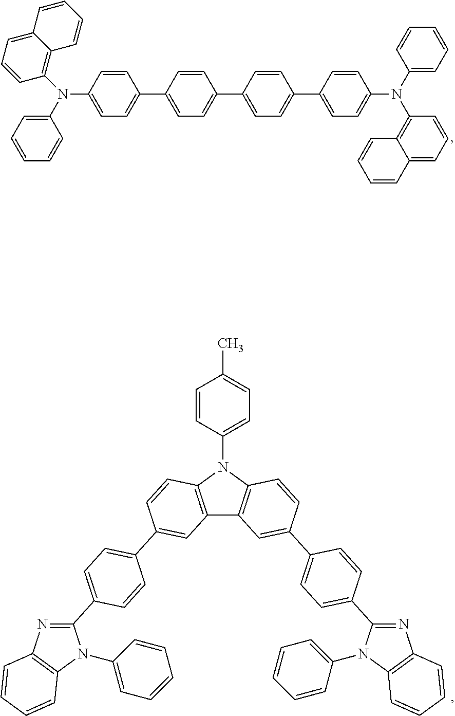
A hole-transport layer, e.g., the hole-transport layer 125, may be any layer that is capable of transporting holes from one layer to another, such as from a hole-injection layer to an emissive layer, or from an anode to an emissive layer, etc. A hole-transport layer may comprise any of a variety of materials. For example, a hole-transport layer material may comprise 4,4′-bis[N-(naphthyl)-N-phenyl-amino]biphenyl (NPB) (see structure below), an aromatic-substituted amine, a carbazole, a polyvinylcarbazole (PVK), e.g. poly(9-vinylcarbazole); polyfluorene; a polyfluorene copolymer; poly(9,9-di-n-octylfluorene-alt-benzothiadiazole); poly(paraphenylene); poly[2-(5-cyano-5-methylhexyloxy)-1,4-phenylene]; a benzidine; a phenylenediamine; a phthalocyanine metal complex; a polyacetylene; a polythiophene; a triphenylamine; copper phthalocyanine; 1,1-Bis(4-bis(4-methylphenyl)aminophenyl) cyclohexane; 2,9-Dimethyl-4,7-diphenyl-1,10-phenanthroline; 3,5-Bis(4-tert-butyl-phenyl)-4-pheny[1,2,4]triazole; 3,4,5-Triphenyl-1,2,3-triazole; 4,4′,4′-tris(3-methylphenylphenylamino)triphenylamine (MTDATA); N,N′-bis(3-methylphenyl)N,N′-diphenyl-[1,1′-biphenyl]-4,4′-diamine (TPD); 4,4′,4″-tris(carbazol-9-yl)-triphenylamine (TCTA); 4,4′-bis[N,N′-(3-tolyl)amino]-3,3′-dimethylbiphenyl (HMTPD); 4,4′-N,N′-dicarbazole-biphenyl (CBP); 1,3-N,N-dicarbazole-benzene (mCP); Bis[4-(p,p′-ditolyl-amino)phenyl]diphenylsilane (DTASi); 2,2′-bis(4-carbazolylphenyl)-1,1′-biphenyl (4CzPBP); N,N′N″-1,3,5-tricarbazoloylbenzene (tCP); N,N′-bis(4-butylphenyl)-N,N′-bis(phenyl)benzidine; a combination thereof; or any other material known in the art to be useful as a hole-transport material.
A hole-transport layer may optionally further comprise a dopant material such as transition metal oxide such as MoO3, V2O5, WO3, organic hole-injection materials such as CuPc, PEDOT, etc. In some embodiments, a hole-transport layer may comprise NPB and a dopant such as MoO3. A hole-transport layer may be partially doped so that a discreet thickness of the layer near the emissive layer may remain undoped while the remainder of the layer is doped. A hole-transport layer may have a thickness that can vary. For example, a hole-transport layer may have a thickness of about 0.01 nm, about 1 nm, about 5 nm, about 10 nm, about 20 nm, about 30 nm, about 40 nm, about 50 nm, about 60 nm, or any thickness in a range bounded by, or between, any of these values. In some embodiments, a hole-transport layer may have a thickness in a range of about 0.1 nm to about 60 nm, about 1 nm to about 50 nm, or about 20 nm to about 50 nm.
In some embodiments, a hole-transport layer 120 may be a combination of sublayers. For example, as shown in FIG. 1F , the hole-transport layer 120 may comprise a first hole-transport sublayer 122, disposed on hole-injection layer 115, and a second hole-transport sublayer 124, disposed on the first hole-transport sublayer 122. An emissive component 160 may be disposed on the second hole-transport sublayer 124. In some embodiments, the hole-transport layer may be partially doped. A partially doped hole-transport layer may comprise a first hole-transport sublayer 122 that is doped and a second hole-transport sublayer 124 that is undoped or a first hole-transport sublayer 122 that is undoped and a second hole-transport sublayer 124 that is doped. In some embodiments, a partially doped hole-transport layer may be a single layer having gradient doping instead of two or more distinct sublayers.
In some embodiments, a first hole-transport sublayer, e.g., the first hole-transport sublayer layer 122, may have a thickness of about 0.01 nm, about 1 nm, about 5 nm, about 10 nm, about 20 nm, about 30 nm, or any thickness in a range bounded by, or between, any of these values. In some embodiments, a first hole-transport sublayer may have a thickness in the range of about 0.01 nm to about 30 nm, about 1 nm to about 30 nm, or about 5 nm to about 30 nm.
In some embodiments, a second hole-transport sublayer, e.g., the second hole-transport sublayer layer 124, may have a thickness of about 1 nm, about 5 nm, about 10 nm, about 20 nm, about 30 nm, or any thickness in a range bounded by, or between, any of these values. In some embodiments, a second hole-transport sublayer may have a thickness in the range of about 1 nm to about 30 nm, about 1 nm to about 30 nm, or about 5 nm to about 30 nm.
In some embodiments, the first hole-transport sublayer may comprise NPB and a MoO3 dopant. The concentration of MoO3 in the first hole-transport sublayer may be about 5 wt %. The first hole-transport sublayer may have a thickness of about 5 nm to about 30 nm and may be disposed on the hole-injection layer.
In some embodiments, the second hole-transport sublayer may consist of NPB. The second hole-transport layer may have a thickness of about 10 nm.
In some embodiments an emissive component 160 comprises a first fluorescent light-emitting layer; a second fluorescent light-emitting layer; and an intervening phosphorescent light-emitting layer disposed between the first fluorescent light-emitting layer and the second fluorescent light-emitting layer. In some embodiments, additional phosphorescent light-emitting layers, such as a second intervening phosphorescent light-emitting layer, a third intervening phosphorescent light-emitting layer, etc., may be disposed between the intervening phosphorescent light-emitting layer and one of the first or second fluorescent light-emitting layers. For example, each intervening phosphorescent light-emitting layer may contain a phosphorescent dopant having a different color emission than the dopants of any other phosphorescent layers. With respect to the emissive components configured as described above, at least a portion of any intervening phosphorescent light-emitting layer may directly contact any of the corresponding luminescent light-emitting layers described above.
In some embodiments an emissive component 160 comprises a first phosphorescent light-emitting layer; a second phosphorescent light-emitting layer; and an intervening fluorescent light-emitting layer disposed between the first phosphorescent light-emitting layer and the second phosphorescent light-emitting layer. In some embodiments, additional intervening fluorescent light-emitting layers, such as a second intervening fluorescent light-emitting layer, a third intervening fluorescent light-emitting layer, etc., may be disposed between the intervening fluorescent light-emitting layer and one of the first or second phosphorescent light-emitting layers. For example, each fluorescent light-emitting layer may contain a fluorescent dopant having a different color emission than any dopants of any other phosphorescent layers. With respect to the emissive components configured as described above, at least a portion of any intervening fluorescent light-emitting layer may directly contact any of the corresponding phosphorescent light-emitting layers described above.
The composition of a fluorescent light-emitting layer may vary. If there are two fluorescent light-emitting layers, such as a first fluorescent light-emitting layer and a second fluorescent light-emitting layer, the two layers may have the same composition and/or physical properties, or may be different.
A fluorescent light-emitting layer, e.g. the first fluorescent light-emitting layer 125, the second light-emitting layer 135, and/or the intervening fluorescent light-emitting layer 126 may comprise a doped or undoped fluorescent host material, such as a fluorescent ambipolar host material which has blue emission. The wavelength properties of blue light may vary. For example, blue light may have a peak emission or an average emissive wavelength of about 430 nm, about 450 nm, about 480 nm, about 500 nm, or any wavelength in a range bounded by, or between, any of these values. In some embodiments, a fluorescent host material may have a peak emission or an average emissive wavelength in the range of about 430 nm to about 500 nm, about 430 nm to about 480 nm, about 450 to about 480 nm, or about 450 nm to about 500 nm.
A peak emission includes a wavelength where there appears to be a peak on a plot of a visible spectrum of a material. An average emissive wavelength is a wavelength at which the area of the plot of a visible spectrum at wavelengths lower than the average emissive wavelength is about equal to the area of the plot of a visible spectrum at wavelengths higher than the average emissive wavelength.
A fluorescent light-emitting layer, e.g. the first fluorescent light-emitting layer 125, the second light-emitting layer 135, and/or the intervening fluorescent light-emitting layer 126 may comprise a material, such as an ambipolar host material, that may have a triplet energy that is greater than a triplet energy of the phosphorescent light-emitting layer. This may allow the triplet energy of the fluorescent layer to be transferred to the phosphorescent layer, where it may be emitted as phosphorescence. Thus, the triplet energy may produce phosphorescent emission instead of being lost by a nonradiative relaxation process in the fluorescent layer. This three-layer design may improve the efficiency of a light-emitting device.
In some embodiments, the fluorescent light-emitting layer, e.g. the first fluorescent light-emitting layer 125, the second light-emitting layer 135, and/or the intervening fluorescent light-emitting layer 126 may comprise a compound selected from the group consisting of:
The fluorescent light-emitting layer may also comprise any fluorescent compound or host material described in any of the following documents: U.S. Provisional Application No. 61/221,472 or U.S. Patent Application Publication No. 2010/0326526, both of which are incorporated by reference in their entireties, and particularly for the purpose of describing fluorescent compounds and host materials.
The thickness of a fluorescent light-emitting layer may vary. For example, a fluorescent light-emitting layer may have a thickness of about 5 nm, about 10 nm, about 15 nm, about 20 nm, about 30 nm, about 50 nm, about 80 nm, about 100 nm, or any thickness in a range bounded by, or between, any of these values. In some embodiments, the thickness of a fluorescent light-emitting layer may be in a range of about 5 nm to about 100 nm, about 5 nm to about 50 nm, or about 10 nm to about 20 nm.
The composition of a phosphorescent light-emitting layer may vary. If there are two phosphorescent light-emitting layers, such as a first phosphorescent light-emitting layer and a second phosphorescent light-emitting layer, the two layers may have the same composition and/or physical properties, or may be different.
A phosphorescent light-emitting layer, e.g. the first phosphorescent light-emitting layer 131, the second phosphorescent light-emitting layer 132, and/or the intervening phosphorescent light-emitting layer 130 may emit any color light. In some embodiments, a phosphorescent light-emitting layer may emit orange light. The wavelength properties of orange light may vary. For example, orange light may have a peak emission or an average emissive wavelength of about 570 nm, about 585 nm, about 600 nm, about 620 nm, 630 nm, 650 nm, or any wavelength in a range bounded by, or between, any of these values. In some embodiments, the phosphorescent light-emitting layer may have a peak emission or an average emissive wavelength of about 570 nm to about 650 nm, about 585 nm to about 650 nm, about 570 nm to about 630 nm, or about 585 nm to about 630 nm.
A phosphorescent light-emitting layer, e.g. the first phosphorescent light-emitting layer 131, the second phosphorescent light-emitting layer 132, and/or the intervening phosphorescent light-emitting layer 130 may comprise a host, such as a blue emitting host, and a phosphorescent dopant material, such as an orange emitting phosphorescent dopant material. A combination of phosphorescent dopants may be used, such as a combination of two or more phosphorescent emitters that emit visible light in the red to green range. Such a combination of phosphorescent dopants may be combined in a single phosphorescent layer or in more than one distinct phosphorescent layer. Some phosphorescent light-emitting layers, or combination of layers, may comprise a combination of at least two of: a red emitter, a green emitter, and a yellow emitter.
The wavelength ranges of red, green, yellow, and emitters of other colors may overlap. One of the reasons for this is that the color perceived may vary by individual, for example a color may appear red to one person and orange to another person, or it may be difficult for an individual to decide whether a color is orange or red. For example, green emitters may have a peak emission or an average emissive wavelength of about 480 nm, about 490 nm, about 500 nm, about 550 nm, about 570 nm, about 580 nm, or any wavelength in a range bounded by, or between, any of these values. In some embodiments, a green emitter may have a peak emission or an average emissive wavelength in the range of about 490 nm to about 570 nm, about 500 nm to about 570 nm, or about 490 nm to about 550 nm. Yellow emitters may have a peak emission or an average emissive wavelength of about 565 nm, 570 nm, 575 nm, 580 nm, 585 nm, 590 nm, or any wavelength in a range bounded by, or between, any of these values. In some embodiments, a yellow emitter may have a peak emission or an average emissive wavelength in the range of 570 nm to about 585 nm, about 575 nm to about 585 nm, or about 570 nm to about 580 nm. Red emitters may have a peak emission or an average emissive wavelength of about 610 nm, 620 nm, 630 nm, 650 nm, 700 nm, 750 nm, 780 nm, 800 nm, or any wavelength in a range bounded by, or between, any′ of these values. In some embodiments, a red emitter may have a peak emission or an average emissive wavelength in the range of about 620 nm to about 780 nm, about 630 nm to about 780 nm, or about 620 nm to about 750 nm.
Some phosphorescent light-emitting layers may comprise a combination of a green emitter and a red emitter, or a combination of a yellow emitter and red emitter. In some embodiments, a phosphorescent light-emitting layer may comprise two phosphorescent emitters, wherein each emitter emits visible light in the red to green range, e.g. about 480 nm to about 800 nm, about 490 nm to about 780 nm, about 490 to about 750 nm, or about 500 nm to about 780 nm.
The color of the light emitted by an emissive component may be tuned according to any phosphorescent dopants used. For example, the color of the emitted light may depend upon the color of the light emitted from a phosphorescent dopant. The color of the emitted light may also depend upon the concentration of a phosphorescent dopant. For example, an increased concentration of a green phosphorescent dopant may make the light emitted by an emissive component to be greener, or an increased concentration of an orange phosphorescent dopant may make the light emitted by an emissive component more orange, etc. Thus, the color may be tuned to obtain a white light-emitting emissive component, or an emissive component that emits any desired color.
In some embodiments, a phosphorescent dopant may comprise an Ir complex. Some examples of phosphorescent dopants comprising an Ir complex may include Ir-(pq)2acac, Ir(phq)2acac, Ir(piq)2acac, Ir(piq)3, YE-1; YE-2, etc. For example, the first phosphorescent dopant and/or the second phosphorescent dopant may comprise at least one of: Ir-(pq)2acac, Ir(phq)2acac, Ir(piq)2acac, Ir(piq)3, YE-1, and YE-2. Some phosphorescent light-emitting layers may comprise YE-2 and Ir(piq)2acac.
In some embodiments, if the host is a blue emitting host, the host may be one of the materials of a fluorescent light-emitting layer described above. In some embodiments, the host of a phosphorescent light-emitting layer is the same as a host material of a fluorescent light-emitting layer. In some embodiments, any one or combination of the first phosphorescent light-emitting layer, the second phosphorescent light-emitting layer, or the intervening phosphorescent light-emitting layer may comprise the fluorescent host material of the first fluorescent light-emitting layer. Depending upon the structure of the emissive layers, the second fluorescent light-emitting layer may be undoped fluorescent host material of the first fluorescent light-emitting layer, or the second phosphorescent light-emitting layer may also comprise the fluorescent host material of the first fluorescent light-emitting layer.
The thickness of a phosphorescent light-emitting layer may vary. In some embodiments, the thickness of a phosphorescent light-emitting layer may be about 1 nm, about 5 nm, about 10 nm, about 50 nm, about 80 nm, about 100 nm, or any thickness in a range bounded by, or between, any of these values. In some embodiments, the thickness of a phosphorescent light-emitting layer may be in a range of about 1 nm to about 100 nm, about 1 nm to about 50 nm, or about 1 nm to about 10 nm.
In some embodiments, the phosphorescent light-emitting layer, e.g. the first phosphorescent light-emitting layer 131, the second phosphorescent light-emitting layer 132, and/or the intervening phosphorescent light-emitting layer 130 comprises:
a host comprising Host-1:
about 5% by weight of YE-2; and about 0.5% by weight of Ir(piq)2acac; wherein the thickness of the phosphorescent light-emitting layer is about 5 nm.
An electron-transport layer, e.g., the electron-transport layer 140, may comprise at least one electron-transport material. Examples of electron-transport materials may include: 2-(4-biphenylyl)-5-(4-tert-butylphenyl)-1,3,4-oxadiazole (PBD); 1,3-bis(N,N-t-butylphenyl)-1,3,4-oxadiazole (OXD-7), 1,3-bis[2-(2,2′-bipyridine-6-yl)-1,3,4-oxadiazo-5-yl]benzene; 3-phenyl-4-(1′-naphthyl)-5-phenyl-1,2,4-triazole (TAZ); 2,9-dimethyl-4,7-diphenyl-phenanthroline (bathocuproine or BCP); aluminum tris(8-hydroxyquinolate) (Alq3); and 1,3,5-tris(2-N-phenylbenzimidazolyl)benzene; 1,3-bis[2-(2,2′-bipyridine-6-yl)-1,3,4-oxadiazo-5-yl]benzene (BPY-OXD); 3-phenyl-4-(1′-naphthyl)-5-phenyl-1,2,4-triazole (TAZ), 2,9-dimethyl-4,7-diphenyl-phenanthroline (bathocuproine or BCP); and 1,3,5-tris[2-N-phenylbenzimidazol-z-yl]benzene (TPBI). In some embodiments, the electron transport layer may be aluminum quinolate (Alq3), 2-(4-biphenylyl)-5-(4-tert-butylphenyl)-1,3,4-oxadiazole (PBD), phenanthroline, quinoxaline, 1,3,5-tris[N-phenylbenzimidazol-z-yl]benzene (TPBI), a derivative or a combination thereof, or any other material known in the art to be useful as an electron-transport material.
The thickness of the electron-transport layer may vary. For example, the electron-transport layer may have thickness of: about 1 nm, about 5 nm, about 10 nm, about 20 nm, about 30 nm, about 40 nm, about 50 nm, about 60 nm, or any thickness in a range bounded by, or between, any of these values. In some embodiments, an electron-transport layer may have thickness in a range of about 1 nm to about 60 nm, about 5 nm to about 50 nm, or about 20 nm to about 40 nm.
Some optional layers may comprise an exciton-blocking material. Examples of exciton-blocking materials may include an optionally substituted compound selected from the following: 4,4′-bis[N-(naphthyl)-N-phenyl-amino]biphenyl (α-NPD), 4,4′-N,N′-dicarbazole-biphenyl (CBP), and bathocuproine (BCP), and any other material(s) that have a large enough band gap to substantially prevent the diffusion of excitons.
Some optional layers may comprise an electron-injection material. Examples of suitable electron injection materials may include but are not limited to: LiF, CsF, Cs doped into electron-transport material as described above or a derivative or a combination thereof.
An enhancement layer, e.g., the enhancement layer 150, may be any layer that enhances the emission of light from an OLED device. An enhancement layer may comprise any material that is capable of increasing the emission of light by an OLED device. An enhancement layer may comprise any material that is substantially transparent to visible light. In one embodiment, substantially transparent materials may transmit at least 75% of the visible light impinging upon it. In some embodiments, substantially transparent materials may transmit at least 80%, 85%, 90%, 95% and/or 97% of the visible light impinging upon it. In an embodiment, the enhancement layer comprises a visible light substantially transparent material having refractive index higher than about 1.5. Examples of such materials may include, but are not limited to, transparent materials including organic small molecule materials such as NPB, TPBI, Alq3; metal oxides such as MoO3, WO3, SnO2 and SnO; wide band gap semiconductor compounds; etc.
The refractive index of a material of an enhancement layer may vary. For example, an enhancement layer may comprise a material having refractive index of about 1.5, about 1.6, about 1.8, about 2, about 2.5, or any refractive index in a range bounded by, or between, any of these values. In some embodiments, an enhancement layer may comprise a material having refractive index in a range of about 1.5 to about 2.5, about 1.6 to about 2.5, or about 1.5 to about 2.
The thickness of an enhancement layer may vary. For example, the enhancement layer may have a thickness of about 0.01 nm, about 1 nm, about 10 nm, about 20 nm, about 40 nm, about 50 nm, about 60 nm, about 70 nm, about 80 nm, about 100 nm, about 150 nm, about 200 nm, or any thickness in a range bounded by, or between, any of these values. In some embodiments, an enhancement layer may have a thickness in a range of about 0.01 nm to about 200 nm, about 1 nm to about 100 nm, or about 40 nm to about 80 nm.
A light-scattering layer, e.g., the light-scattering layer 155, may be any layer that is capable of scattering light. A light-scattering layer may comprise any material and may have any morphology that is capable of scattering light. In some embodiments, a light-scattering layer may comprise a porous film.
The thickness of a light-scattering layer may vary. In some embodiments, a light-scattering layer may have a thickness in the nanometer to micro range. For example, the thickness of the film may be about 500 nm, about 0.1 μm, about 1 μm, about 1.3 μm, about 3 μm, or about 4 μm, about 5 μm, about 7 μm, about 10 μm, about 20 μm, about 100 μm, or any thickness in a range bounded by, or between, any of these values. In some embodiments, the light scattering layer may have a thickness in the range of about 0.1 nm to about 10 μm, about 1 μm to about 10 μm, or about 1 μm to about 5 μm.
If a light-scattering layer comprises a porous film, a porous film may have a variety of structures. In some embodiments, a porous film may have a surface comprising a plurality of irregularly arranged protrusions, particles, or aggregates thereof. The protrusions or particles may be nanoprotrusions, including nanoprotrusions having one or more dimensions in the nanometer to micron range. For example, nanoprotrusions or nanoparticles may have: an average largest dimension of about 400 nm, about 500 nm, about 1000 nm, about 1500 nm, about 2000 nm, about 2500 nm, about 3000 nm, or any value in a range bounded by, or between, any of these lengths; and/or an average smallest dimension of about 10 nm, about 30 nm, about 50 nm, about 70 nm, about 90 nm, about 100 nm, or any value in a range bounded by, or between, any of these lengths. In some embodiments, at least one particle in the film, or average of the particles in the film, may any dimension of: about 5 nm, about 0.01 μm, about 0.02 μm, about 0.05 μm, about 0.1 μm, about 0.5 μm, about 1 μm, about 2 μm, about 5 μm, about 10 μm, about 20 μm, about 50 μm, about 100 μm, about 150 μm, about 200 μm, about 500 μm, about 1000 μm, or any length bounded by, or between, any of these values. In some embodiments, the nanoprotrusions or nanoparticles may have: an average x dimension in the range of about 400 nm to about 3000 nm, about 1000 nm to about 3000 nm, or about 2000 nm to about 3000 nm; an average y dimension in the range of about 100 nm to about 2000 nm, about 100 nm to about 1500 nm, or about 100 nm to about 1000 nm; and/or an average z dimension of about 10 nm to about 100 nm, about 30 nm to about 90 nm, or about 30 nm to about 70 nm. In some embodiments, at least one particle in the film, or average of the particles in the film, may have an x dimension, a y dimension, or a z dimension in the range of: about 5 nm to about 1000 μm, about 0.02 μm to about 1 μm, or about 1 μm to about 200 μm.
A porous film may comprise a pore or a void. For example, a porous film may comprises a plurality of voids having a total volume that may be about 50%, about 70%, about 80%; about 85%, about 90%, about 95%, or about 99% of the volume of the film including the voids, or any percentage of total volume in a range bounded by, or between, any of these values. Thus, if the total volume of the voids is 50% of the volume of the film, 50% of the volume of the film is the material of the film and 50% of the volume of the film is the plurality of voids. In some embodiments, a porous film may comprises a plurality of voids having a total volume in the range of about 50% to about 99%, about 80% to about 99%, or about 95% to about 99% of the volume of the film.
In some embodiments, a light-scattering layer may comprise a porous film that may comprises a plurality of voids of a number and size such that the film may have a thickness that is about 2 times, about 10 times; up to about 50 times, or 100 times, that of the thickness of a film of the same material which has no voids, or any thickness ratio in a range bounded by, or between, any of these values. For example, a film may have a thickness of about 5 μm when a film of the same material would have a thickness of 800 nm if the film had no voids. In some embodiments, the film may have a thickness that is in the range of about 2 times to about 100 times or about 2 to about 10 times that of the thickness of a film of the same material which has no voids.
The size of the voids in a light-scattering layer may vary. In some embodiments, at least about 10% of the voids have a largest dimension of about 0.5 μm, about 1 μm, about 2 μm, about 3 μm, about 4 μm, about 5 μm, or any length in a range bounded by, or between, any of these values. In some embodiments, at least one void in the film, or average of the voids in the film, may have any dimension of: about 5 nm, about 0.01 μm, about 0.02 μm, about 0.05 μm, about 0.1 μm, about 0.5 μm, about 1 μm, about 2 μm, about 5 μm, about 10 μm, about 20 μm, about 50 μm, about 100 μm, about 150 μm, about 200 μm, about 500 μm, about 1000 μm, or any length bounded by, or between, any of these values. In some embodiments, at least one void in the film, or an average of the voids in the film, may have an x dimension, a y dimension, or a z dimension in the range of: about 0.01 μm to about 5 μm, about 0.01 μm to about 1 μm, about 0.01 μm to about 10 μm, about 0.01 μm to about 20 μm, about 0.01 μm to about 5 μm, about 0.02 μm to about 10 μm, about 0.05 μm to about 10 μm, about 0.1 μm to about 10 μm, about 0.1 μm to about 100 μm, about 0.1 μm to about 150 μm, about 0.1 μm to about 20 μm, about 0.1 μm to about 5 μm, about 0.5 μm to about 50 μm, about 1 μm to about 100 μm, about 1 μm to about 20 μm, about 1 μm to about 200 μm, about 1 μm to about 50 μm, about 1 μm to about 500 μm, about 10 μm to about 50 μm, about 10 nm to about 5 μm, about 2 μm to about 100 μm, about 20 μm to about 1000 μm, about 5 nm to about 5 μm, about 50 nm to about 2 μm, or about 50 nm to about 5 μm.
The density of a light-scattering layer may vary, and may be affected by the voids, the material, and other factors. In some embodiments, the density of the film including the voids may be about 0.005 picograms/μm3, about 0.05 picograms/μm3, about 0.1 picograms/μm3, about 0.3 picograms/μm3, about 0.5 picograms/μm3, about 0.9 picograms/μm3, or any density in a range bounded by, or between, any of these values. In some embodiments, the including the voids may be in the range of about: about 0.005 picograms/μm3 to about 0.9 picograms/μm3, about 0.05 picograms/μm3 to about 0.7 picograms/μm3, or about 0.1 picograms/μm3 to about 0.5 picograms/μm3.
The refractive index of the material of the light-scattering layer may vary. For example, the refractive index may be about 1.1, about 1.5, about 1.7, about 1.8, or any refractive index in a range bounded by, or between, any of these values. In some embodiments, the refractive index of the material of the porous film may be greater than or equal to that of the substrate. In some embodiments, the refractive index may be in the range of about 1.1 to about 1.8, about 1.1 to about 1.7, or about 1.1 to about 1.5.
A light-scattering layer may comprise a material that includes an organic compound, such as a non-polymeric organic compound that may comprise an optionally substituted aromatic ring. In some embodiments, the light-scattering layer may comprise at least one of the compounds below:
Other compounds that may be useful in light-scattering layers include any compound described in one of the following documents: U.S. Provisional Application No. 61/221,427, filed Jun. 29, 2009, which is incorporated by reference herein in its entirety and particularly for the purpose of describing such compounds; US 20100326526, which is incorporated by reference herein its entirety and particularly for the purpose of describing such compounds; U.S. Provisional Patent Application No. 61/383,602, filed Sep. 16, 2010, which is incorporated by reference herein in its entirety and particularly for the purpose of describing such compounds; and U.S. Provisional Application No. 61/426,259, filed Dec. 22, 2010, which is incorporated by reference herein in its entirety and particularly for the purpose of describing such compounds.
A porous film for a light-scattering layer may be prepared by depositing a material on a surface, such as a substrate or a light enhancement layer. In some embodiments, the material may be deposited on a substantially transparent layer. Deposition and/or subsequent annealing conditions may affect the characteristics of the film.
The rate of deposition of the material on, a surface may vary. For example, the deposition rate may be: about 0.1 A/sec, about 0.2 A/sec, about 1 A/sec, about 10 A/sec, about 100 A/sec, about 500 A/sec, about 1000 A/sec, or any value in a range bounded by, or between, any of these deposition rates.
The material may be deposited onto a variety of surfaces to form a film. For some devices, the material may be deposited onto an anode, a cathode, or a transparent layer.
A material that has been deposited on a surface may be further treated by heating or annealing. The temperature of heating may vary. For example, the a precursor material may be heated at a temperature of about 100° C., about 110° C., about 120° C., about 150° C., about 180° C., about 200° C., about 130° C., about 260° C., about 290° C., or any temperature in a range bounded by, or between, any of these values.
The time of heating may also vary. For example, the material may be heated for about 5 minutes, about 15 minutes, about 30 minutes, about 60 minutes, or any amount of time in a range bounded by, or between, any of these values. In some embodiments, a material may be heated at about 100° C. to about 260° C. for about 5 minutes to about 30 minutes.
In some embodiments a light-scattering layer may comprise Compound-2 and may have a density of about 80% and/or a thickness greater than about 4 μm. In some embodiments, Compound-2 may be heated at about 110° C. and/or heating may be carried out for about 60 min.
In some embodiments a light-scattering layer may comprise Compound-3 and may have a thickness of about 1.3 μm. In some embodiments, Compound-3 may be heated at about 180° C. and/or heating may be carried out for about 15 minutes.
Other examples of porous films that may be used in light-scattering layer are included in U.S. Provisional Application No. 61/449,032, filed Mar. 3, 2011 with the title “Porous Films For Use In Light-Emitting Devices,” which is incorporated by reference in its entirety herein.
Device A was prepared having a structure consistent with that depicted in FIG. 1 . The layers of the device, from bottom to top were: a substrate 105 [Glass (0.7 mm)/ITO (55 nm)/PEDOT (30 nm); a reflective-opaque anode 110 (Al, 50 nm; then Ag, 50 nm); a hole-injection layer 115 (MoO3, 10 nm); a hole-transport layer 120 (NPB:MoO3 [5%], 20 nm; NPB, 10 nm); a blue emissive layer 125 (Host-1, 15 nm); an orange phosphorescent layer 130 (Host-1:YE-2 [5%]:Ir(piq)2acac [0.5%], 5 nm); a blue emissive layer 135 (Host-1, 15 nm); an electron-transport layer 140 (TPBI, 30 nm); a semi-transparent cathode 145 (bottom layer of Ca, 4 nm; top layer of Au, 12 nm); an enhancement layer 150 (SnO2, 60 nm); and a light-scattering layer 155 (Compound-2, 4000 nm).
A series of devices were prepared with the same structure as Device A except that they had no light-scattering layer. Instead, varying thicknesses (0 nm, 20 nm, 40 nm, 60 nm, 80 nm, and 100 nm) of the enhancement layer 150 (SnO2) were provided. The results are shown in FIG. 2 . It was found that with an enhancement layer having a thickness of about 80 nm, the highest power efficiency enhancement, a factor of 2.7, was achieved. In addition, at 1000 nits, the power efficiency was enhanced to 34.9 lm/w. The color of the device was high white, the CIE was (0.48, 0.41) and showed high viewing angle dependence. FIG. 3 shows the electroluminescence (EL) spectrum without a light-scattering layer at viewing angle of (a) 0 and (b) 80°.
Device A, with the light-scattering layer, showed white color and very small viewing angle dependence. The EL spectrum and the lighting image of Device A are depicted in FIG. 4 at a viewing angle of (a) 0 and (b) 80°.
The EL spectrum of Device A were similar at different viewing angles with a CIE of (0.41, 0.40) at 0° and (0.39, 0.41) at 80°. FIG. 5 is a plot of current density (mA/cm2) and brightness (cd/m2) as a function of driving voltage of Device A. The device shows a low turn-on voltage of 2.5V. FIG. 6 is a plot of power efficiency (PE) and luminance efficiency (LE) as a function of device brightness of Device A. Device A has a high power efficiency (30 lm/w) at 1000 nit with working voltage of 3.9V (FIG. 6 ). Device A also has a CRI greater than about 75.
Pre-cleaned ITO glass substrates were baked at about 200° C. for about 1 hour under an ambient environment, then under UV-ozone treatment for about 30 minutes. Then, a PEDOT layer (about 30 nm thick) was spin-coated on top of the substrates' surface at 6000 RPM for about 40 seconds to smooth the surface. Then the substrates were baked at about 180° C. for about 1 hour. The substrates were then loaded into a deposition chamber.
A bi-layer reflective bottom anode, (60 nm Al layer first and then a 10 nm Ag layer) were deposited sequentially at a rate of about 2 Å/s. Molybdenum oxide (MoO3, about 20 nm) was deposited as a hole-injecting layer at deposition rate of about 1 Å/s. Then a p-doping layer (10 nm), MoO3, was co-deposited with 4,4′-bis[N-(naphthyl)-N-phenyl-amino]biphenyl (NPB) at 5% in volume ratio at the deposition rate of about 0.05 and about 1 Å/s for MoO3 and NPB, respectively. A layer of NPB (about 10 nm) was then deposited as a hole-transport layer, followed by the deposition of the fluorescent blue emissive layer (18 nm), fluorescent blue (BE-1) neat layer was deposited at 1 Å/s.
This was followed by the three co-deposition of phosphorescent emissive layer (5 nm), which comprised a red phosphorescent emitter (Ir(piq)2acac) at 0.5% volume concentration, and a yellow phosphorescent emitter (YE-1) at 5% volume concentration, and a host (BE-1). Then, another fluorescent blue emissive neat layer (18 nm, BE-1) was deposited. The electron transporting layer (35 nm) of 1,3,5-Tris(1-phenyl-1H-benzimidazol-)2-yl)benzene (TPBI) was deposited on top of the upper fluorescent blue emissive layer at about 1 Å/s. The semitransparent cathode, which comprised bi-layer metals of Ca and Au, was added. The first 4 nm of thickness was Ca deposited on top of the TPBI layer, followed by the deposition a 12 nm thick Au layer to finish the cathode deposition.
The light enhancement layer (SnO2, 80 nm) was deposited on top of the cathode to enhance the light output, followed by the deposition of light scattering layer (3,5-bis(3-(benzo[d]oxazol-2-yl)phenyl)pyridine) at about 1 Å/s to a thickness of about 900 nm to complete the device fabrication. All the deposition was done in high vacuum of about 3×10⁻⁷ torr.
Although the subject matter of the claims have been disclosed in the context of certain embodiments and examples, it will be understood by those skilled in the art that the scope of the claims extends beyond the specifically disclosed embodiments to other alternative embodiments and/or uses of the invention and obvious modifications and equivalents thereof. Thus, it is intended that the scope of the present claims should not be limited by the particular disclosed embodiments described above.
Claims (21)
1. A light-emitting device comprising:
a substrate;
a reflective anode over the substrate;
a hole-injection layer over the reflective anode;
a hole-transport layer over the hole-injection layer;
an emissive component over the hole-transport layer, wherein the emissive component comprises:
a first fluorescent light-emitting layer;
a second fluorescent light-emitting layer; and
an intervening phosphorescent light-emitting layer disposed between the first fluorescent light-emitting layer and the second fluorescent light-emitting layer; or wherein the emissive component comprises:
a first phosphorescent light-emitting layer;
a second phosphorescent light-emitting layer; and
an intervening fluorescent light-emitting layer disposed between the first phosphorescent light-emitting layer and the second phosphorescent light-emitting layer; an electron-transport layer over the emissive component;
a semi-transparent or transparent cathode over the electron-transport layer;
an enhancement layer over the semi-transparent or transparent cathode; and
a light-scattering layer over the enhancement layer;
wherein the first fluorescent light-emitting layer, the second fluorescent light-emitting layer, and the intervening fluorescent light-emitting layer each comprises a fluorescent ambipolar host material selected from the group consisting of:
2. The light-emitting device of claim 1 , wherein the reflective anode comprises a first anode sublayer and a second anode sublayer, wherein the first anode sublayer comprises a material selected from the group consisting of Al, Ag, Ni, and combinations thereof, and wherein the second anode sublayer comprises a material selected from the group consisting of Ag, Al, Au, and combinations thereof.
3. The light-emitting device of claim 1 , wherein the hole-injection layer comprises a high work function material.
4. The light-emitting device of claim 1 , wherein the hole-transport layer comprises 4,4′-bis[N-(naphthyl)-N-phenyl-amino]biphenyl.
5. The light-emitting device of claim 4 , wherein the hole-transport layer further comprises a MoO3 dopant.
6. The light-emitting device of claim 1 , wherein the hole-transport layer comprises:
a first hole-transport sublayer comprising 4,4′-bis[N-(naphthyl)-N-phenyl-amino]biphenyl and a dopant, wherein the dopant is MoO3; and
a second hole-transport sublayer comprising 4,4′-bis[N-(naphthyl)-N-phenyl-amino]biphenyl, wherein the second hole-transport sublayer is substantially free of MoO3.
7. The light-emitting device of claim 1 , wherein the fluorescent ambipolar host material has a peak emission in the range of about 430 nm to about 500 nm.
8. The light-emitting device of claim 1 , wherein the first phosphorescent light-emitting layer and the second phosphorescent light-emitting layer each comprises a host and a phosphorescent dopant material, or the intervening phosphorescent light-emitting layer comprises the host and the phosphorescent dopant material, wherein the phosphorescent dopant material has a peak emission in the range of about 570 nm to about 650 nm.
9. The light-emitting device of claim 1 , wherein the first phosphorescent light-emitting layer and the second phosphorescent light-emitting layer each comprises a host, or the intervening phosphorescent light-emitting layer comprises the host, wherein the host comprises:
about 5% by weight, based on the weight of the phosphorescent light-emitting layer, of the following compound:
10. The light-emitting device of claim 1 , wherein the first phosphorescent light-emitting layer and the second phosphorescent light-emitting layer each comprises two phosphorescent emitters, or the intervening phosphorescent light-emitting layer comprises two phosphorescent emitters, wherein each phosphorescent emitter emits visible light having a peak emission in the red to green range.
11. The light-emitting device of claim 1 , wherein the electron-transport layer comprises 1,3,5-tris[2-N-phenylbenzimidazol-z-yl]benzene.
12. The light-emitting device of claim 1 , wherein the semi-transparent or transparent cathode comprises a first cathode sublayer comprising materials selected from Mg, Ca, Mg/Ag, LiF/Al, CsF, CsF/Al or alloys thereof and a second cathode sublayer comprising materials selected from Al, Ag, Au, Cu, Mg/Ag, or alloys thereof.
13. The light-emitting device of claim 1 , wherein the enhancement layer comprises a visible light substantially transparent material having refractive index higher than about 1.5.
15. The light-emitting device of claim 1 , wherein the light-scattering layer comprises voids having a volume that is at least about 50% of the volume of the light-scattering layer.
16. The light-emitting device of claim 1 , wherein the light-scattering layer has a thickness in the range of about 0.1 μm to about 10 μm.
17. The light-emitting claim 1 , wherein at least a portion of the first fluorescent light-emitting layer and at least a portion of the intervening phosphorescent light-emitting layer directly contact one another.
18. The light-emitting device claim 17 , wherein at least a portion of the second fluorescent light-emitting layer and at least a portion of the intervening phosphorescent light-emitting layer directly contact one another.
19. The light-emitting device claim 1 , wherein at least a portion of the first phosphorescent light-emitting layer and at least a portion of the intervening fluorescent light-emitting layer directly contact one another.
20. The light-emitting device claim 19 , wherein at least a portion of the second phosphorescent light-emitting layer and at least a portion of the intervening fluorescent light-emitting layer directly contact one another.
21. The light-emitting device of claim 1 , wherein:
the first fluorescent light-emitting layer is undoped;
the intervening phosphorescent light-emitting layer comprises a fluorescent host material of the first fluorescent light-emitting layer; and
the second fluorescent light-emitting layer is undoped, or the second fluorescent light-emitting layer comprises the fluorescent host material of the first fluorescent light-emitting layer.
Priority Applications (1)
Application Number | Priority Date | Filing Date | Title |
---|---|---|---|
US14/344,300 US9853220B2 (en) | 2011-09-12 | 2012-09-11 | Efficient organic light-emitting diodes and fabrication of the same |
Applications Claiming Priority (3)
Application Number | Priority Date | Filing Date | Title |
---|---|---|---|
US201161533679P | 2011-09-12 | 2011-09-12 | |
PCT/US2012/054664 WO2013039914A1 (en) | 2011-09-12 | 2012-09-11 | Efficient organic light-emitting diodes and fabrication of the same |
US14/344,300 US9853220B2 (en) | 2011-09-12 | 2012-09-11 | Efficient organic light-emitting diodes and fabrication of the same |
Publications (2)
Publication Number | Publication Date |
---|---|
US20150041780A1 US20150041780A1 (en) | 2015-02-12 |
US9853220B2 true US9853220B2 (en) | 2017-12-26 |
Family
ID=46934720
Family Applications (1)
Application Number | Title | Priority Date | Filing Date |
---|---|---|---|
US14/344,300 Active 2035-04-29 US9853220B2 (en) | 2011-09-12 | 2012-09-11 | Efficient organic light-emitting diodes and fabrication of the same |
Country Status (2)
Country | Link |
---|---|
US (1) | US9853220B2 (en) |
WO (1) | WO2013039914A1 (en) |
Cited By (1)
Publication number | Priority date | Publication date | Assignee | Title |
---|---|---|---|---|
US20220109105A1 (en) * | 2020-10-02 | 2022-04-07 | Universal Display Corporation | Application of nanoparticles for plasmon energy extraction in organic devices |
Families Citing this family (23)
Publication number | Priority date | Publication date | Assignee | Title |
---|---|---|---|---|
WO2012064987A1 (en) | 2010-11-11 | 2012-05-18 | Nitto Denko Corporation | Hybrid composite emissive construct and light-emitting devices using the same |
US9853220B2 (en) | 2011-09-12 | 2017-12-26 | Nitto Denko Corporation | Efficient organic light-emitting diodes and fabrication of the same |
KR102072253B1 (en) * | 2012-03-14 | 2020-01-31 | 가부시키가이샤 한도오따이 에네루기 켄큐쇼 | Light-emitting element, light-emitting device, display device, electronic device, and lighting device |
DE102012207151A1 (en) * | 2012-04-30 | 2013-10-31 | Osram Opto Semiconductors Gmbh | ORGANIC LIGHT-EMITTING COMPONENT AND METHOD FOR PRODUCING AN ORGANIC LIGHT-EMITTING COMPONENT |
US9203045B2 (en) * | 2012-11-29 | 2015-12-01 | Semiconductor Energy Laboratory Co., Ltd. | Light-emitting element, light-emitting device, electronic device, and lighting device |
TWI592463B (en) * | 2012-12-10 | 2017-07-21 | 日東電工股份有限公司 | Bipolar hosts for light emitting devices |
CN103666460A (en) * | 2013-12-27 | 2014-03-26 | 武汉大学 | Low-triplet-state-energy-level blue-light phosphorescent main body material and application thereof |
KR102089271B1 (en) * | 2013-12-31 | 2020-03-16 | 엘지디스플레이 주식회사 | Organic Light Emitting Device |
CN104022229A (en) * | 2014-05-30 | 2014-09-03 | 京东方科技集团股份有限公司 | OLED device, manufacturing method thereof and display device |
KR102242140B1 (en) * | 2014-11-10 | 2021-04-20 | 엘지디스플레이 주식회사 | Hetero compounds and organic light emitting devices comprising the same |
EP3303514A1 (en) * | 2015-05-29 | 2018-04-11 | Dow Global Technologies LLC | Organic composition and electronic device comprising organic layer comprising said composition |
CN105098095B (en) * | 2015-07-27 | 2017-05-31 | 京东方科技集团股份有限公司 | A kind of organic light emitting diode device and preparation method thereof, display device |
KR20170030427A (en) * | 2015-09-09 | 2017-03-17 | 주식회사 엘지화학 | Organoluminescent device |
KR102650330B1 (en) * | 2016-08-24 | 2024-03-21 | 엘지디스플레이 주식회사 | Organic light emitting display device |
JP2018181970A (en) * | 2017-04-07 | 2018-11-15 | 株式会社ジャパンディスプレイ | Display, and method for manufacturing display |
KR20190007942A (en) * | 2017-07-14 | 2019-01-23 | 코닝 인코포레이티드 | Method of patterning multi-layer structure |
JP2019204810A (en) * | 2018-05-21 | 2019-11-28 | パイオニア株式会社 | Light-emitting device and method of manufacturing light-emitting device |
KR20190140233A (en) * | 2018-06-11 | 2019-12-19 | 엘지디스플레이 주식회사 | An electroluminescent compound and an electroluminescent device comprising the same |
US20210013437A1 (en) * | 2018-09-29 | 2021-01-14 | Tcl Technology Group Corporation | Quantum dot light-emitting diode |
US11139442B2 (en) * | 2019-03-12 | 2021-10-05 | Universal Display Corporation | Nanopatch antenna outcoupling structure for use in OLEDs |
US11637261B2 (en) | 2019-03-12 | 2023-04-25 | Universal Display Corporation | Nanopatch antenna outcoupling structure for use in OLEDs |
US11569480B2 (en) | 2019-03-12 | 2023-01-31 | Universal Display Corporation | Plasmonic OLEDs and vertical dipole emitters |
CN111740025A (en) * | 2020-08-12 | 2020-10-02 | 河南大学 | QLED device based on vanadium-doped molybdenum oxide and preparation method thereof |
Citations (52)
Publication number | Priority date | Publication date | Assignee | Title |
---|---|---|---|---|
US20020192441A1 (en) | 2000-05-30 | 2002-12-19 | The Penn State Research Foundation | Electronic and opto-electronic devices fabricated from nanostructured high surface to volume ratio thin films |
JP2003195775A (en) | 2001-12-27 | 2003-07-09 | Seiko Epson Corp | Electro-optical device, manufacturing method therefor, circuit board, manufacturing method therefor, and electronic equipment |
CN1498046A (en) | 2002-10-01 | 2004-05-19 | ��˹���´﹫˾ | Organic luminescent device with enhanced light extraction efficiency |
WO2004049465A2 (en) | 2002-11-22 | 2004-06-10 | Luxell Technologies Inc. | Transparent-cathode for top-emission organic light-emitting diodes |
US20050156520A1 (en) | 2004-01-19 | 2005-07-21 | Jun Tanaka | Organic light emitting diode display and method for manufacturing the same |
JP2005235753A (en) | 2004-01-19 | 2005-09-02 | Hitachi Displays Ltd | Organic electroluminescent display device and its manufacturing method |
CN1711651A (en) | 2002-11-12 | 2005-12-21 | 皇家飞利浦电子股份有限公司 | Organic electroluminescent light source with an anti-reflection coating |
US6984934B2 (en) | 2001-07-10 | 2006-01-10 | The Trustees Of Princeton University | Micro-lens arrays for display intensity enhancement |
WO2006009039A1 (en) | 2004-07-22 | 2006-01-26 | Idemitsu Kosan Co., Ltd. | Color light-emitting device |
WO2006035596A1 (en) * | 2004-09-28 | 2006-04-06 | Toshiba Matsushita Display Technology Co., Ltd. | Display |
US7053547B2 (en) | 2001-11-29 | 2006-05-30 | Universal Display Corporation | Increased emission efficiency in organic light-emitting devices on high-index substrates |
US20060186802A1 (en) | 2005-02-24 | 2006-08-24 | Eastman Kodak Company | Oled device having improved light output |
US7109652B2 (en) | 2002-10-23 | 2006-09-19 | Tpo Displays Corp. | Top emission light emitting display having reflective layer |
US20060232194A1 (en) | 2005-04-13 | 2006-10-19 | Yeh-Jiun Tung | Hybrid OLED having phosphorescent and fluorescent emitters |
WO2006112265A1 (en) | 2005-04-14 | 2006-10-26 | Konica Minolta Holdings, Inc. | Organic electroluminescent device, display and illuminating device |
WO2006130883A2 (en) * | 2005-06-01 | 2006-12-07 | The Trustees Of Princeton University | Fluorescent filtered electrophosphorescence |
US20060286403A1 (en) | 2005-06-20 | 2006-12-21 | Au Optronics Corp. | Organic light emitting diode and method of fabricating the same |
TWI284009B (en) | 2004-12-13 | 2007-07-11 | Toyota Ind Corp | Organic EL device |
US7345300B2 (en) | 2002-05-24 | 2008-03-18 | Dashan Qin | Phosphorescent light-emitting component comprising organic layers |
US20080102310A1 (en) | 2006-10-27 | 2008-05-01 | Thompson Mark E | Materials and architectures for efficient harvesting of singlet and triplet excitons for white light emitting OLEDs |
US20080157665A1 (en) | 2005-02-25 | 2008-07-03 | Optimax Technology Corporation | Optical Thin Films with Nano-Corrugated Surface Topologies by a Simple Coating Method |
CN101274916A (en) | 2008-05-06 | 2008-10-01 | 武汉大学 | Multifunctional bipolar carrier transmission material and application thereof |
US20080258606A1 (en) | 2004-10-08 | 2008-10-23 | Cambridge Display Technology Limited | Light Emitting Device |
WO2008131750A2 (en) | 2007-04-30 | 2008-11-06 | Novaled Ag | Light-emitting component and method for the production thereof |
US20080278067A1 (en) | 2007-05-10 | 2008-11-13 | Yuan-Sheng Tyan | Electroluminescent device having improved light output |
US20080297029A1 (en) | 2007-05-31 | 2008-12-04 | Cok Ronald S | Electroluminescent device having improved light output |
WO2009009695A1 (en) | 2007-07-10 | 2009-01-15 | University Of Florida Research Foundation, Inc. | Top-emission organic light-emitting devices with microlens arrays |
US20090033212A1 (en) | 2007-01-19 | 2009-02-05 | Samsung Electronics Co., Ltd. | White organic light emitting device |
US20090039294A1 (en) | 2007-08-07 | 2009-02-12 | Osram Opto Semiconductors Gmbh | Radiation emitting device |
US20090091255A1 (en) | 2007-10-09 | 2009-04-09 | Sung-Hoon Lee | White organic light emitting device |
US20090115319A1 (en) | 2007-11-07 | 2009-05-07 | Kim Mu-Gyeom | White organic light emitting device |
US20090174308A1 (en) | 2002-12-26 | 2009-07-09 | Semiconductor Energy Laboratory Co., Ltd. | Organic light emitting element and a light emitting device using the same |
US20090212694A1 (en) | 2008-02-27 | 2009-08-27 | Cok Ronald S | Led device having improved light output |
US20090224660A1 (en) | 2008-03-10 | 2009-09-10 | Tsutomu Nakanishi | Light-extraction layer of light-emitting device and organic electroluminescence element employing the same |
WO2010016990A1 (en) | 2008-08-08 | 2010-02-11 | University Of North Texas | Organic light-emitting diodes from homoleptic square planar complexes |
US20100052527A1 (en) | 2008-09-01 | 2010-03-04 | Semiconductor Energy Laboratory Co., Ltd. | Light Emitting Element, Light Emitting Device, and Electronic Device |
WO2010024572A2 (en) | 2008-08-25 | 2010-03-04 | Cheil Industries Inc. | Material for organic photoelectric device and organic photoelectric device including the same |
US20100051968A1 (en) | 2008-09-01 | 2010-03-04 | Semiconductor Energy Laboratory Co., Ltd. | Light-Emitting Element, Light-Emitting Device, and Electronic Device |
EP2166589A1 (en) * | 2007-07-07 | 2010-03-24 | Idemitsu Kosan Co., Ltd. | Organic el device |
US20100078631A1 (en) | 2008-09-30 | 2010-04-01 | Sung Hoon Pieh | Organic light emitting diode display device |
US20100159792A1 (en) | 2008-12-22 | 2010-06-24 | Vitex Systems, Inc. | Encapsulated white oleds having enhanced optical output |
US20100213452A1 (en) | 2009-02-03 | 2010-08-26 | Nitto Denko Corporation | Ambipolar host in organic light emitting diode |
US7816021B2 (en) | 2007-01-18 | 2010-10-19 | Samsung Mobile Display Co., Ltd. | Carbazole-based compound and organic light-emitting device including organic layer including the carbazole-based compound |
US20100326526A1 (en) | 2009-06-29 | 2010-12-30 | Nitto Denko Corporation | Emissive aryl-heteroaryl compounds |
US7867631B2 (en) | 2007-01-15 | 2011-01-11 | Samsung Mobile Display Co., Ltd. | Fluorine-containing compound and organic light-emitting device employing the same |
US20110156059A1 (en) | 2007-04-30 | 2011-06-30 | Novaled Ag | Light-Emitting Component and Method for The Production Thereof |
WO2012064987A1 (en) | 2010-11-11 | 2012-05-18 | Nitto Denko Corporation | Hybrid composite emissive construct and light-emitting devices using the same |
US20120223635A1 (en) | 2011-03-03 | 2012-09-06 | Nitto Denko Corporation | Porous films for use in light-emitting devices |
WO2013039914A1 (en) | 2011-09-12 | 2013-03-21 | Nitto Denko Corporation | Efficient organic light-emitting diodes and fabrication of the same |
US9051284B2 (en) | 2011-03-03 | 2015-06-09 | Nitto Denko Corporation | Compounds for porous films in light-emitting devices |
US20150228907A1 (en) | 2012-08-31 | 2015-08-13 | Nitto Denko Corporation | Porous Films for Use in Light-Emitting Devices |
US9328086B2 (en) | 2010-09-16 | 2016-05-03 | Nitto Denko Corporation | Substituted bipyridines for use in organic light-emitting devices |
-
2012
- 2012-09-11 US US14/344,300 patent/US9853220B2/en active Active
- 2012-09-11 WO PCT/US2012/054664 patent/WO2013039914A1/en active Application Filing
Patent Citations (59)
Publication number | Priority date | Publication date | Assignee | Title |
---|---|---|---|---|
US20020192441A1 (en) | 2000-05-30 | 2002-12-19 | The Penn State Research Foundation | Electronic and opto-electronic devices fabricated from nanostructured high surface to volume ratio thin films |
US6984934B2 (en) | 2001-07-10 | 2006-01-10 | The Trustees Of Princeton University | Micro-lens arrays for display intensity enhancement |
US7053547B2 (en) | 2001-11-29 | 2006-05-30 | Universal Display Corporation | Increased emission efficiency in organic light-emitting devices on high-index substrates |
JP2003195775A (en) | 2001-12-27 | 2003-07-09 | Seiko Epson Corp | Electro-optical device, manufacturing method therefor, circuit board, manufacturing method therefor, and electronic equipment |
US7345300B2 (en) | 2002-05-24 | 2008-03-18 | Dashan Qin | Phosphorescent light-emitting component comprising organic layers |
CN1498046A (en) | 2002-10-01 | 2004-05-19 | ��˹���´﹫˾ | Organic luminescent device with enhanced light extraction efficiency |
US7109652B2 (en) | 2002-10-23 | 2006-09-19 | Tpo Displays Corp. | Top emission light emitting display having reflective layer |
CN1711651A (en) | 2002-11-12 | 2005-12-21 | 皇家飞利浦电子股份有限公司 | Organic electroluminescent light source with an anti-reflection coating |
US20060220518A1 (en) | 2002-11-12 | 2006-10-05 | Koninklijke Philips Electric, N.V. | Organic electroluminescent light source with anti-reflection coating |
JP2006505909A (en) | 2002-11-12 | 2006-02-16 | コーニンクレッカ フィリップス エレクトロニクス エヌ ヴィ | Organic electroluminescent light source with anti-reflective coating |
WO2004049465A2 (en) | 2002-11-22 | 2004-06-10 | Luxell Technologies Inc. | Transparent-cathode for top-emission organic light-emitting diodes |
US20090174308A1 (en) | 2002-12-26 | 2009-07-09 | Semiconductor Energy Laboratory Co., Ltd. | Organic light emitting element and a light emitting device using the same |
US20050156520A1 (en) | 2004-01-19 | 2005-07-21 | Jun Tanaka | Organic light emitting diode display and method for manufacturing the same |
JP2005235753A (en) | 2004-01-19 | 2005-09-02 | Hitachi Displays Ltd | Organic electroluminescent display device and its manufacturing method |
WO2006009039A1 (en) | 2004-07-22 | 2006-01-26 | Idemitsu Kosan Co., Ltd. | Color light-emitting device |
WO2006035596A1 (en) * | 2004-09-28 | 2006-04-06 | Toshiba Matsushita Display Technology Co., Ltd. | Display |
US20080258606A1 (en) | 2004-10-08 | 2008-10-23 | Cambridge Display Technology Limited | Light Emitting Device |
TWI284009B (en) | 2004-12-13 | 2007-07-11 | Toyota Ind Corp | Organic EL device |
US20060186802A1 (en) | 2005-02-24 | 2006-08-24 | Eastman Kodak Company | Oled device having improved light output |
US20080157665A1 (en) | 2005-02-25 | 2008-07-03 | Optimax Technology Corporation | Optical Thin Films with Nano-Corrugated Surface Topologies by a Simple Coating Method |
US20060232194A1 (en) | 2005-04-13 | 2006-10-19 | Yeh-Jiun Tung | Hybrid OLED having phosphorescent and fluorescent emitters |
WO2006112265A1 (en) | 2005-04-14 | 2006-10-26 | Konica Minolta Holdings, Inc. | Organic electroluminescent device, display and illuminating device |
US20090236974A1 (en) | 2005-04-14 | 2009-09-24 | Konica Minolta Holdings, Inc. | Organic electroluminescent device, display and illuminating device |
WO2006130883A2 (en) * | 2005-06-01 | 2006-12-07 | The Trustees Of Princeton University | Fluorescent filtered electrophosphorescence |
US20060286403A1 (en) | 2005-06-20 | 2006-12-21 | Au Optronics Corp. | Organic light emitting diode and method of fabricating the same |
US20080102310A1 (en) | 2006-10-27 | 2008-05-01 | Thompson Mark E | Materials and architectures for efficient harvesting of singlet and triplet excitons for white light emitting OLEDs |
US7867631B2 (en) | 2007-01-15 | 2011-01-11 | Samsung Mobile Display Co., Ltd. | Fluorine-containing compound and organic light-emitting device employing the same |
US7816021B2 (en) | 2007-01-18 | 2010-10-19 | Samsung Mobile Display Co., Ltd. | Carbazole-based compound and organic light-emitting device including organic layer including the carbazole-based compound |
US20090033212A1 (en) | 2007-01-19 | 2009-02-05 | Samsung Electronics Co., Ltd. | White organic light emitting device |
US20110156059A1 (en) | 2007-04-30 | 2011-06-30 | Novaled Ag | Light-Emitting Component and Method for The Production Thereof |
WO2008131750A2 (en) | 2007-04-30 | 2008-11-06 | Novaled Ag | Light-emitting component and method for the production thereof |
US20080278067A1 (en) | 2007-05-10 | 2008-11-13 | Yuan-Sheng Tyan | Electroluminescent device having improved light output |
US20080297029A1 (en) | 2007-05-31 | 2008-12-04 | Cok Ronald S | Electroluminescent device having improved light output |
EP2166589A1 (en) * | 2007-07-07 | 2010-03-24 | Idemitsu Kosan Co., Ltd. | Organic el device |
WO2009009695A1 (en) | 2007-07-10 | 2009-01-15 | University Of Florida Research Foundation, Inc. | Top-emission organic light-emitting devices with microlens arrays |
US20090039294A1 (en) | 2007-08-07 | 2009-02-12 | Osram Opto Semiconductors Gmbh | Radiation emitting device |
US20090091255A1 (en) | 2007-10-09 | 2009-04-09 | Sung-Hoon Lee | White organic light emitting device |
US20090115319A1 (en) | 2007-11-07 | 2009-05-07 | Kim Mu-Gyeom | White organic light emitting device |
US20090212694A1 (en) | 2008-02-27 | 2009-08-27 | Cok Ronald S | Led device having improved light output |
US20090224660A1 (en) | 2008-03-10 | 2009-09-10 | Tsutomu Nakanishi | Light-extraction layer of light-emitting device and organic electroluminescence element employing the same |
CN101274916A (en) | 2008-05-06 | 2008-10-01 | 武汉大学 | Multifunctional bipolar carrier transmission material and application thereof |
WO2010016990A1 (en) | 2008-08-08 | 2010-02-11 | University Of North Texas | Organic light-emitting diodes from homoleptic square planar complexes |
WO2010024572A2 (en) | 2008-08-25 | 2010-03-04 | Cheil Industries Inc. | Material for organic photoelectric device and organic photoelectric device including the same |
US20100051968A1 (en) | 2008-09-01 | 2010-03-04 | Semiconductor Energy Laboratory Co., Ltd. | Light-Emitting Element, Light-Emitting Device, and Electronic Device |
US20100052527A1 (en) | 2008-09-01 | 2010-03-04 | Semiconductor Energy Laboratory Co., Ltd. | Light Emitting Element, Light Emitting Device, and Electronic Device |
US20100078631A1 (en) | 2008-09-30 | 2010-04-01 | Sung Hoon Pieh | Organic light emitting diode display device |
US20100159792A1 (en) | 2008-12-22 | 2010-06-24 | Vitex Systems, Inc. | Encapsulated white oleds having enhanced optical output |
US20100213452A1 (en) | 2009-02-03 | 2010-08-26 | Nitto Denko Corporation | Ambipolar host in organic light emitting diode |
JP2012532135A (en) | 2009-06-29 | 2012-12-13 | 日東電工株式会社 | Luminescent aryl-heteroaryl compounds |
US20100326526A1 (en) | 2009-06-29 | 2010-12-30 | Nitto Denko Corporation | Emissive aryl-heteroaryl compounds |
WO2011008560A1 (en) | 2009-06-29 | 2011-01-20 | Nitto Denko Corporation | Emissive aryl-heteroaryl compounds |
US9328086B2 (en) | 2010-09-16 | 2016-05-03 | Nitto Denko Corporation | Substituted bipyridines for use in organic light-emitting devices |
US8604689B2 (en) | 2010-11-11 | 2013-12-10 | Nitto Denko Corporation | Hybrid composite emissive construct and light-emitting devices using the same |
WO2012064987A1 (en) | 2010-11-11 | 2012-05-18 | Nitto Denko Corporation | Hybrid composite emissive construct and light-emitting devices using the same |
WO2012119111A1 (en) | 2011-03-03 | 2012-09-07 | Nitto Denko Corporation | Porous films for use in light-emitting devices |
US20120223635A1 (en) | 2011-03-03 | 2012-09-06 | Nitto Denko Corporation | Porous films for use in light-emitting devices |
US9051284B2 (en) | 2011-03-03 | 2015-06-09 | Nitto Denko Corporation | Compounds for porous films in light-emitting devices |
WO2013039914A1 (en) | 2011-09-12 | 2013-03-21 | Nitto Denko Corporation | Efficient organic light-emitting diodes and fabrication of the same |
US20150228907A1 (en) | 2012-08-31 | 2015-08-13 | Nitto Denko Corporation | Porous Films for Use in Light-Emitting Devices |
Non-Patent Citations (14)
Cited By (1)
Publication number | Priority date | Publication date | Assignee | Title |
---|---|---|---|---|
US20220109105A1 (en) * | 2020-10-02 | 2022-04-07 | Universal Display Corporation | Application of nanoparticles for plasmon energy extraction in organic devices |
Also Published As
Publication number | Publication date |
---|---|
WO2013039914A1 (en) | 2013-03-21 |
US20150041780A1 (en) | 2015-02-12 |
Similar Documents
Publication | Publication Date | Title |
---|---|---|
US9853220B2 (en) | Efficient organic light-emitting diodes and fabrication of the same | |
US9722200B2 (en) | Top-emitting white organic light-emitting diodes having improved efficiency and stability | |
US9614162B2 (en) | Light-emitting devices comprising emissive layer | |
US9917281B2 (en) | Top-emitting white organic light-emitting diodes having improved efficiency and stability | |
US8933439B2 (en) | Organic light-emitting diode with enhanced efficiency | |
KR101688317B1 (en) | Organic light emitting diode having low operating voltage and method for fabricating the same | |
US9859517B2 (en) | White organic light-emitting diode | |
US9190626B2 (en) | Organic light emitting diode having low driving voltage, high brightness, and excellent light emitting efficiencies | |
US10522788B2 (en) | Organic light emitting diode | |
TWI495708B (en) | Stacked organoluminescent device | |
JP5167380B2 (en) | Organic electroluminescence device | |
JP5180338B2 (en) | Organic electroluminescence device | |
WO2015031752A2 (en) | Light-emitting devices | |
JP2013084986A (en) | Organic electroluminescent element | |
JP2013084620A (en) | Organic electroluminescent element | |
KR20130135196A (en) | Organoluminescent device | |
JP2013069702A (en) | Organic electroluminescent element | |
JP2013062262A (en) | Organic electroluminescent device |
Legal Events
Date | Code | Title | Description |
---|---|---|---|
AS | Assignment |
Owner name: NITTO DENKO CORPORATION, JAPAN Free format text: ASSIGNMENT OF ASSIGNORS INTEREST;ASSIGNOR:MA, LIPING;REEL/FRAME:032823/0938 Effective date: 20110930 |
|
STCF | Information on status: patent grant |
Free format text: PATENTED CASE |
|
MAFP | Maintenance fee payment |
Free format text: PAYMENT OF MAINTENANCE FEE, 4TH YEAR, LARGE ENTITY (ORIGINAL EVENT CODE: M1551); ENTITY STATUS OF PATENT OWNER: LARGE ENTITY Year of fee payment: 4 |