US9835824B2 - Camera lens system - Google Patents
Camera lens system Download PDFInfo
- Publication number
- US9835824B2 US9835824B2 US15/011,485 US201615011485A US9835824B2 US 9835824 B2 US9835824 B2 US 9835824B2 US 201615011485 A US201615011485 A US 201615011485A US 9835824 B2 US9835824 B2 US 9835824B2
- Authority
- US
- United States
- Prior art keywords
- lens
- refractive power
- camera
- image side
- group
- Prior art date
- Legal status (The legal status is an assumption and is not a legal conclusion. Google has not performed a legal analysis and makes no representation as to the accuracy of the status listed.)
- Active, expires
Links
Images


Classifications
-
- G—PHYSICS
- G02—OPTICS
- G02B—OPTICAL ELEMENTS, SYSTEMS OR APPARATUS
- G02B9/00—Optical objectives characterised both by the number of the components and their arrangements according to their sign, i.e. + or -
- G02B9/62—Optical objectives characterised both by the number of the components and their arrangements according to their sign, i.e. + or - having six components only
-
- G—PHYSICS
- G02—OPTICS
- G02B—OPTICAL ELEMENTS, SYSTEMS OR APPARATUS
- G02B13/00—Optical objectives specially designed for the purposes specified below
- G02B13/001—Miniaturised objectives for electronic devices, e.g. portable telephones, webcams, PDAs, small digital cameras
- G02B13/0015—Miniaturised objectives for electronic devices, e.g. portable telephones, webcams, PDAs, small digital cameras characterised by the lens design
- G02B13/002—Miniaturised objectives for electronic devices, e.g. portable telephones, webcams, PDAs, small digital cameras characterised by the lens design having at least one aspherical surface
- G02B13/0045—Miniaturised objectives for electronic devices, e.g. portable telephones, webcams, PDAs, small digital cameras characterised by the lens design having at least one aspherical surface having five or more lenses
-
- G—PHYSICS
- G02—OPTICS
- G02B—OPTICAL ELEMENTS, SYSTEMS OR APPARATUS
- G02B13/00—Optical objectives specially designed for the purposes specified below
- G02B13/18—Optical objectives specially designed for the purposes specified below with lenses having one or more non-spherical faces, e.g. for reducing geometrical aberration
-
- G—PHYSICS
- G02—OPTICS
- G02B—OPTICAL ELEMENTS, SYSTEMS OR APPARATUS
- G02B27/00—Optical systems or apparatus not provided for by any of the groups G02B1/00 - G02B26/00, G02B30/00
- G02B27/0025—Optical systems or apparatus not provided for by any of the groups G02B1/00 - G02B26/00, G02B30/00 for optical correction, e.g. distorsion, aberration
-
- G—PHYSICS
- G02—OPTICS
- G02B—OPTICAL ELEMENTS, SYSTEMS OR APPARATUS
- G02B3/00—Simple or compound lenses
- G02B3/02—Simple or compound lenses with non-spherical faces
- G02B3/04—Simple or compound lenses with non-spherical faces with continuous faces that are rotationally symmetrical but deviate from a true sphere, e.g. so called "aspheric" lenses
-
- G—PHYSICS
- G02—OPTICS
- G02B—OPTICAL ELEMENTS, SYSTEMS OR APPARATUS
- G02B9/00—Optical objectives characterised both by the number of the components and their arrangements according to their sign, i.e. + or -
- G02B9/60—Optical objectives characterised both by the number of the components and their arrangements according to their sign, i.e. + or - having five components only
Definitions
- the present invention relates to a camera lens system which can be used in smart phones, digital cameras and other portable terminal devices, monitors and PC camera lens for video recording or image capturing.
- the demand on the small size, high resolution camera lens of the smart phones or portable devices, monitor lens, PC camera lens and digital cameras etc. is growing.
- a camera lens system including 4 lenses is used usually to correct astigmatism for higher performance of the lens system in recent time.
- the demand on the image resolution is not high due to larger pixel size, three or less lens groups can be used.
- 3 to 4 lens groups are used for the lens with high resolution demand due to the small pixel size and high demand on the image.
- FIG. 1 is the structural diagram of a camera lens system in accordance with an exemplary embodiment of the present invention
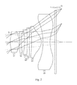
- FIG. 2 is the light ray structural diagram of the camera lens system shown in FIG. 1 ;
- FIG. 3 is the longitudinal spherical aberration, astigmatic field curves and distortion of the camera lens system shown in FIG. 1 ;
- FIG. 4 is MTF curve diagram of the camera lens system shown in FIG. 1 .
- the first lens group G2 The second lens group G3: The third lens group G4: The fourth lens group G5: The fifth lens group L1: The first lens L2: The second lens L3: The third lens L4: The fourth lens L5: The fifth lens L6: The sixth lens R2, R3, . . . : The curvature radius of the aperture, lens and optical filter.
- the present invention provides a camera lens system.
- the camera lens system 10 shown in FIGS. 1-2 is an exemplary embodiment of the present invention.
- the camera lens system 10 includes 5 lens groups lined up from the object side to the image side surface: an aperture St, a first lens group G1, a second lens group G2, a third lens group G3, a fourth lens group G4 and a fifth lens group G5.
- An optical filter Lf and other optical materials are contained between the fifth lens group G5 and the image side surface Si.
- the first lens group G1 includes a first lens L1.
- the second lens group G2 includes a second lens L2.
- the third lens group G3 includes a third lens L3 and a fourth lens L4.
- the fourth lens group G4 includes a fifth lens L5.
- the fifth lens group G5 includes a sixth lens L6.
- the first lens L1 has a positive refractive power and its object side surface is outwardly convex.
- the first lens L1 is a biconvex lens.
- the second lens L2 has a negative refractive power.
- the object side surface is outwardly convex and the image side surface is inwardly concave.
- the third lens L3 has a positive refractive power.
- the object side surface of the third lens L3 is convex and the image side surface is convex.
- the fourth lens L4 has a negative refractive power.
- the image side surface of the third lens L3 is connected to the object side surface of the fourth lens L4.
- the object side surface of the fourth lens L4 is concave and the image side surface is concave.
- a contact surface between the third lens L3 and the fourth lens L4 is sphere, i.e. the third lens and the fourth lens are connected by a spherical face. It is easier to produce and process the lens and can also reduce the spherical aberration, astigmatism and distortion aberration.
- the first lens L1 is a biconvex lens. Therefore, the first lens is easy to process.
- the second lens L2 has a negative refractive power and can reduce the light length. The principal light to the peripheral areas can be gathered and enhanced.
- the contact surface between the third lens L3 and the fourth lens L4 is a spherical face, thereby reducing the difficult degree in precision machining.
- the image side surface of the fifth lens L5 is convex and has a positive refractive power.
- the object side surface of the fifth lens L5 is outwardly convex.
- the sixth lens L6 has a negative refractive power.
- the image side surface of the sixth lens L6 is concave and the object side surface is concave.
- the image side surface of the sixth lens L6 has inflection point.
- the image side surface of the sixth lens L6 is concave at the area close to the optical axis and is convex at the area far away the optical axis.
- the incident angle of principal light to the image side surface is reduced, thereby reducing spherical aberration and astigmatism, and improving the resolution of the lens.
- the object side surface of the sixth lens L6 has also inflection point, i.e. the object side surface of the sixth lens L6 is concave at the area close to the optical axis and is convex at the area far away the optical axis.
- the aperture St and the object side surface of the first lens L1 are located at the same position. It not only reduces total length of the camera lens system, but also reduces the external diameter of the lens, realizing the small size purpose.
- the image side surface of the first lens L1 is outwardly convex and the object side surface of the second lens L2 is inwardly concave.
- the image side surface of the third lens L3 is convex and the object side surface of the fourth lens L4 is concave. The interaction of adjacent convex and concave lenses can reduce the entire length of the camera lens system.
- f is the effective focal length of all lenses and f23 is the synthetic effective focal length of the second lens group G2 and the third lens group G3, thereby satisfying the following condition (1): ⁇ 5.0 ⁇ f 23/ f ⁇ 0 (1)
- the condition (1) above influences maximally the image astigmatism and keeps the optical total length minimal.
- f23/f is smaller than 0, the incident light of all wavelength toward the image side surface is substantially away the focal position, and astigmatism occurs, as a result, the image quality is reduced.
- f23/f is more than 0, the refractive index of the incident light is reduced, and the distance from the object side surface of the first lens group G1 to the image side surface becomes longer, it is difficult to gather light.
- the first lens satisfies the following condition (2): 0.80 ⁇ TTL/ 2 y ⁇ 0.95 (2)
- TTL is the distance from the object side surface to the image side surface of the first lens
- y is the height of the maximal image on the image side surface, i.e. half of the length of diagonal line on the image surface sensor, so 2y is the length of the diagonal line of the image side surface sensor.
- TTL/2y When TTL/2y is more than 0.95, total optical length increases. The optical system cannot be reduced. In addition, when TTL/2y is smaller than 0.80, the refractive index of the lens will be too large, it is not easy to correct the astigmatism of the second lens group and the third lens group, and therefore cannot get a high-performance camera lens system.
- the third lens L3 and the fourth lens L4 form the third lens group G3.
- the third lens L3 has positive refractive power and the fourth lens L4 has negative refractive power. Therefore, the chromatic aberration of the third lens L3 is corrected by the fourth lens L4 which has negative refractive power.
- Vd_L3 represents Abbe number of the third lens and Vd_L4 represents Abbe number of the fourth lens.
- the third lens and the fourth lens satisfy the following condition (3): 20 ⁇ Vd _ L 4 ⁇ Vd _ L 3 ⁇ 40 (3)
- Vd_L4 ⁇ Vd_L3 are lower than 20, the focal length increases and the field-depth becomes small. The image curvature and chromatic astigmatism become larger. If Vd_L4 ⁇ Vd_L3 is more than 40, the spherical astigmatism and chromatic astigmatism become large, the optical total length increases also.
- the second lens L2 and the third lens L3 satisfy the following condition (4) and condition (5): 20 ⁇ Vd _ L 3 ⁇ 30 (4) 50 ⁇ Vd _ L 4 ⁇ 60 (5) Accordingly, the contrast difference shall be reduced, so the color spots are reduced.
- the definition of the aspherical surface derived from the example of the present invention is as follows.
- the aspherical surface takes the optical axis direction as z-axis, the direction perpendicular to the optical axis as h axis, and the advancing direction of the light as the positive direction, so the following formula 1 is derived.
- z represents the distance from the center optical axis to the vertical plane of aspherical vertex of aspheric coordinate point in the height of R.
- a1 is the conic constant and c is the reciprocal of the curvature radius of the lens vertex.
- a4, a6, a8, a10, a12, a14, a16 represent aspherical coefficients.
- Table 1 shows the data of the camera lens system 10 shown in FIG. 1 .
- Table 2 shows the aspherical data.
- Table 1 shows the curvature radius in FIG. 1 as R2, R3, . . . ;
- the thickness or distance shown in FIG. 1 is D1, D2, . . . . Since the aperture and the object side surface of the lens are located at the same position, the distance D1 between the aperture and the object side surface of the first lens 1 is taken as 0 in table 1.
- FIG. 3 is the schematic diagram of the longitudinal spherical aberration, astigmatism field curve and distortion of middle and small camera lens system 10 shown in FIG. 1 .
- the longitudinal spherical aberration diagram shows the light with wavelength of about 65 nm, 587 nm, 486 nm and 435 nm.
- the astigmatism field curve and distortion indicate the light with the wavelength of 546 nm.
- FIG. 4 shows the schematic diagram of MTF resolving power of the camera lens system shown in FIG. 1 .
- X-axis represents the spatial frequency
- Y-axis represents the modulation.
Applications Claiming Priority (2)
| Application Number | Priority Date | Filing Date | Title |
|---|---|---|---|
| KR1020150033974A KR101882990B1 (ko) | 2015-03-11 | 2015-03-11 | 촬영 렌즈계 |
| KR10-2015-0033974 | 2015-03-11 |
Publications (2)
| Publication Number | Publication Date |
|---|---|
| US20160266355A1 US20160266355A1 (en) | 2016-09-15 |
| US9835824B2 true US9835824B2 (en) | 2017-12-05 |
Family
ID=54031009
Family Applications (1)
| Application Number | Title | Priority Date | Filing Date |
|---|---|---|---|
| US15/011,485 Active 2036-04-06 US9835824B2 (en) | 2015-03-11 | 2016-01-30 | Camera lens system |
Country Status (3)
| Country | Link |
|---|---|
| US (1) | US9835824B2 (ko) |
| KR (1) | KR101882990B1 (ko) |
| CN (1) | CN104898257B (ko) |
Cited By (1)
| Publication number | Priority date | Publication date | Assignee | Title |
|---|---|---|---|---|
| US9958650B1 (en) * | 2016-11-02 | 2018-05-01 | Genius Electronic Optical (Xiamen) Co., Ltd. | Optical lens set |
Families Citing this family (10)
| Publication number | Priority date | Publication date | Assignee | Title |
|---|---|---|---|---|
| CN105278081B (zh) * | 2015-07-07 | 2017-12-19 | 瑞声声学科技(深圳)有限公司 | 摄像镜头 |
| CN106526795B (zh) * | 2016-08-05 | 2019-07-26 | 玉晶光电(厦门)有限公司 | 光学镜片组 |
| CN107436477B (zh) * | 2017-09-07 | 2022-10-28 | 浙江舜宇光学有限公司 | 光学成像镜头 |
| TWI703367B (zh) * | 2018-02-08 | 2020-09-01 | 先進光電科技股份有限公司 | 光學成像系統 |
| CN108873261B (zh) * | 2018-08-02 | 2021-01-22 | 诚瑞光学(苏州)有限公司 | 摄像光学镜头 |
| KR102139492B1 (ko) * | 2018-11-27 | 2020-07-29 | 엘컴텍 주식회사 | 렌즈 광학계 |
| CN109375348A (zh) * | 2018-12-24 | 2019-02-22 | 浙江舜宇光学有限公司 | 光学成像系统 |
| CN109856779B (zh) * | 2018-12-31 | 2021-07-30 | 瑞声光学解决方案私人有限公司 | 摄像光学镜头 |
| CN110221408B (zh) * | 2019-06-29 | 2021-08-17 | 瑞声光学解决方案私人有限公司 | 摄像光学镜头 |
| CN111338060B (zh) * | 2020-05-21 | 2020-08-18 | 江西联益光学有限公司 | 光学镜头及成像设备 |
Citations (2)
| Publication number | Priority date | Publication date | Assignee | Title |
|---|---|---|---|---|
| US3586418A (en) * | 1968-03-27 | 1971-06-22 | Minolta Camera Kk | Wide-angle eyepiece lens system |
| US20140111872A1 (en) * | 2012-10-22 | 2014-04-24 | Largan Precision Co., Ltd. | Optical photographing system |
Family Cites Families (13)
| Publication number | Priority date | Publication date | Assignee | Title |
|---|---|---|---|---|
| JPH0850238A (ja) * | 1994-06-01 | 1996-02-20 | Nikon Corp | 広角レンズ |
| KR0135553B1 (ko) | 1995-06-22 | 1998-05-15 | 정몽원 | 반도체식 가속도 검출장치 |
| JP2002162562A (ja) * | 2000-11-27 | 2002-06-07 | Casio Comput Co Ltd | 撮影レンズ |
| KR100800309B1 (ko) | 2006-05-26 | 2008-02-01 | 마루엘에스아이 주식회사 | 자외선 센서, 자외선 센서용 독출 회로 및 자외선 센서를포함하는 이미지 센서 |
| JP2012155223A (ja) * | 2011-01-27 | 2012-08-16 | Tamron Co Ltd | 広角単焦点レンズ |
| TWI432772B (zh) * | 2011-06-10 | 2014-04-01 | Largan Precision Co Ltd | 光學影像擷取透鏡組 |
| TWI435138B (zh) * | 2011-06-20 | 2014-04-21 | Largan Precision Co | 影像拾取光學系統 |
| JP5853522B2 (ja) * | 2011-09-14 | 2016-02-09 | 株式会社リコー | 結像レンズおよびカメラおよび携帯情報端末装置 |
| KR101452045B1 (ko) * | 2012-10-25 | 2014-10-21 | 삼성전기주식회사 | 고해상도 촬상 광학계 |
| JP2014115431A (ja) * | 2012-12-07 | 2014-06-26 | Konica Minolta Inc | 撮像レンズ、撮像装置、及び携帯端末 |
| JP6300183B2 (ja) * | 2013-04-22 | 2018-03-28 | コニカミノルタ株式会社 | 撮像レンズ、撮像装置及び携帯端末 |
| JP2014240918A (ja) * | 2013-06-12 | 2014-12-25 | 富士フイルム株式会社 | 撮像レンズおよび撮像レンズを備えた撮像装置 |
| CN203350521U (zh) * | 2013-06-28 | 2013-12-18 | 东莞市宇瞳光学科技有限公司 | 8mm大孔径日夜两用定焦镜头 |
-
2015
- 2015-03-11 KR KR1020150033974A patent/KR101882990B1/ko active IP Right Grant
- 2015-06-18 CN CN201510338465.2A patent/CN104898257B/zh active Active
-
2016
- 2016-01-30 US US15/011,485 patent/US9835824B2/en active Active
Patent Citations (2)
| Publication number | Priority date | Publication date | Assignee | Title |
|---|---|---|---|---|
| US3586418A (en) * | 1968-03-27 | 1971-06-22 | Minolta Camera Kk | Wide-angle eyepiece lens system |
| US20140111872A1 (en) * | 2012-10-22 | 2014-04-24 | Largan Precision Co., Ltd. | Optical photographing system |
Cited By (1)
| Publication number | Priority date | Publication date | Assignee | Title |
|---|---|---|---|---|
| US9958650B1 (en) * | 2016-11-02 | 2018-05-01 | Genius Electronic Optical (Xiamen) Co., Ltd. | Optical lens set |
Also Published As
| Publication number | Publication date |
|---|---|
| CN104898257A (zh) | 2015-09-09 |
| KR20160110747A (ko) | 2016-09-22 |
| CN104898257B (zh) | 2017-07-18 |
| US20160266355A1 (en) | 2016-09-15 |
| KR101882990B1 (ko) | 2018-07-30 |
Similar Documents
| Publication | Publication Date | Title |
|---|---|---|
| US9835824B2 (en) | Camera lens system | |
| US10215966B2 (en) | Optical image lens system | |
| US20230358999A1 (en) | Photographing system, image capturing unit and electronic device | |
| US10338348B2 (en) | Optical image capturing lens system | |
| US9612423B2 (en) | Camera lens system | |
| US9557530B2 (en) | Photographing optical lens assembly, image capturing unit and mobile device | |
| US9341820B2 (en) | Image capturing optical system, image capturing device and electronic device | |
| US8395691B2 (en) | Optical image-capturing lens assembly | |
| US8462449B2 (en) | Optical lens assembly | |
| US10976523B2 (en) | Optical imaging lens assembly | |
| US8089704B2 (en) | Imaging lens assembly | |
| US10101561B2 (en) | Five-piece optical imaging lens | |
| US20140320981A1 (en) | Photographing lens assembly | |
| US11119296B2 (en) | Imaging optical lens assembly, image capturing unit and electronic device | |
| US20110157449A1 (en) | Photographing Lens Assembly | |
| US11650398B2 (en) | Camera lens assembly | |
| US9354429B2 (en) | Optical imaging lens | |
| US20170184816A1 (en) | Optical imaging lens | |
| US9823449B1 (en) | Optical telephoto imaging lens | |
| US20190121063A1 (en) | Optical imaging lens assembly | |
| CN113156612B (zh) | 光学系统、取像模组及电子设备 |
Legal Events
| Date | Code | Title | Description |
|---|---|---|---|
| AS | Assignment |
Owner name: AAC ACOUSTIC TECHNOLOGIES (SHENZHEN)CO.,LTD, CHINA Free format text: ASSIGNMENT OF ASSIGNORS INTEREST;ASSIGNORS:JANG, ISSAC;PARK, JAY;REEL/FRAME:039980/0345 Effective date: 20160129 |
|
| STCF | Information on status: patent grant |
Free format text: PATENTED CASE |
|
| AS | Assignment |
Owner name: AAC COMMUNICATION TECHNOLOGIES (CHANGZHOU) CO., LTD., CHINA Free format text: ASSIGNMENT OF ASSIGNORS INTEREST;ASSIGNOR:AAC ACOUSTIC TECHNOLOGIES (SHENZHEN) CO., LTD.;REEL/FRAME:052410/0333 Effective date: 20200311 |
|
| AS | Assignment |
Owner name: AAC OPTICS (CHANGZHOU) CO., LTD., CHINA Free format text: CHANGE OF NAME;ASSIGNOR:AAC COMMUNICATION TECHNOLOGIES (CHANGZHOU) CO., LTD.;REEL/FRAME:054090/0347 Effective date: 20200927 |
|
| MAFP | Maintenance fee payment |
Free format text: PAYMENT OF MAINTENANCE FEE, 4TH YEAR, LARGE ENTITY (ORIGINAL EVENT CODE: M1551); ENTITY STATUS OF PATENT OWNER: LARGE ENTITY Year of fee payment: 4 |