US9835824B2 - Camera lens system - Google Patents

Camera lens system Download PDF

Info

Publication number
US9835824B2
US9835824B2 US15/011,485 US201615011485A US9835824B2 US 9835824 B2 US9835824 B2 US 9835824B2 US 201615011485 A US201615011485 A US 201615011485A US 9835824 B2 US9835824 B2 US 9835824B2
Authority
US
United States
Prior art keywords
lens
refractive power
camera
image side
group
Prior art date
Legal status (The legal status is an assumption and is not a legal conclusion. Google has not performed a legal analysis and makes no representation as to the accuracy of the status listed.)
Active, expires
Application number
US15/011,485
Other versions
US20160266355A1 (en
Inventor
Issac Jang
Jay PARK
Current Assignee (The listed assignees may be inaccurate. Google has not performed a legal analysis and makes no representation or warranty as to the accuracy of the list.)
AAC Optics Changzhou Co Ltd
Original Assignee
AAC Acoustic Technologies Shenzhen Co Ltd
Priority date (The priority date is an assumption and is not a legal conclusion. Google has not performed a legal analysis and makes no representation as to the accuracy of the date listed.)
Filing date
Publication date
Application filed by AAC Acoustic Technologies Shenzhen Co Ltd filed Critical AAC Acoustic Technologies Shenzhen Co Ltd
Publication of US20160266355A1 publication Critical patent/US20160266355A1/en
Assigned to AAC ACOUSTIC TECHNOLOGIES (SHENZHEN)CO.,LTD reassignment AAC ACOUSTIC TECHNOLOGIES (SHENZHEN)CO.,LTD ASSIGNMENT OF ASSIGNORS INTEREST (SEE DOCUMENT FOR DETAILS). Assignors: JANG, ISSAC, PARK, JAY
Application granted granted Critical
Publication of US9835824B2 publication Critical patent/US9835824B2/en
Assigned to AAC COMMUNICATION TECHNOLOGIES (CHANGZHOU) CO., LTD. reassignment AAC COMMUNICATION TECHNOLOGIES (CHANGZHOU) CO., LTD. ASSIGNMENT OF ASSIGNORS INTEREST (SEE DOCUMENT FOR DETAILS). Assignors: AAC ACOUSTIC TECHNOLOGIES (SHENZHEN) CO., LTD.
Assigned to AAC OPTICS (CHANGZHOU) CO., LTD. reassignment AAC OPTICS (CHANGZHOU) CO., LTD. CHANGE OF NAME (SEE DOCUMENT FOR DETAILS). Assignors: AAC COMMUNICATION TECHNOLOGIES (CHANGZHOU) CO., LTD.
Active legal-status Critical Current
Adjusted expiration legal-status Critical

Links

Images

Classifications

    • GPHYSICS
    • G02OPTICS
    • G02BOPTICAL ELEMENTS, SYSTEMS OR APPARATUS
    • G02B9/00Optical objectives characterised both by the number of the components and their arrangements according to their sign, i.e. + or -
    • G02B9/62Optical objectives characterised both by the number of the components and their arrangements according to their sign, i.e. + or - having six components only
    • GPHYSICS
    • G02OPTICS
    • G02BOPTICAL ELEMENTS, SYSTEMS OR APPARATUS
    • G02B13/00Optical objectives specially designed for the purposes specified below
    • G02B13/001Miniaturised objectives for electronic devices, e.g. portable telephones, webcams, PDAs, small digital cameras
    • G02B13/0015Miniaturised objectives for electronic devices, e.g. portable telephones, webcams, PDAs, small digital cameras characterised by the lens design
    • G02B13/002Miniaturised objectives for electronic devices, e.g. portable telephones, webcams, PDAs, small digital cameras characterised by the lens design having at least one aspherical surface
    • G02B13/0045Miniaturised objectives for electronic devices, e.g. portable telephones, webcams, PDAs, small digital cameras characterised by the lens design having at least one aspherical surface having five or more lenses
    • GPHYSICS
    • G02OPTICS
    • G02BOPTICAL ELEMENTS, SYSTEMS OR APPARATUS
    • G02B13/00Optical objectives specially designed for the purposes specified below
    • G02B13/18Optical objectives specially designed for the purposes specified below with lenses having one or more non-spherical faces, e.g. for reducing geometrical aberration
    • GPHYSICS
    • G02OPTICS
    • G02BOPTICAL ELEMENTS, SYSTEMS OR APPARATUS
    • G02B27/00Optical systems or apparatus not provided for by any of the groups G02B1/00 - G02B26/00, G02B30/00
    • G02B27/0025Optical systems or apparatus not provided for by any of the groups G02B1/00 - G02B26/00, G02B30/00 for optical correction, e.g. distorsion, aberration
    • GPHYSICS
    • G02OPTICS
    • G02BOPTICAL ELEMENTS, SYSTEMS OR APPARATUS
    • G02B3/00Simple or compound lenses
    • G02B3/02Simple or compound lenses with non-spherical faces
    • G02B3/04Simple or compound lenses with non-spherical faces with continuous faces that are rotationally symmetrical but deviate from a true sphere, e.g. so called "aspheric" lenses
    • GPHYSICS
    • G02OPTICS
    • G02BOPTICAL ELEMENTS, SYSTEMS OR APPARATUS
    • G02B9/00Optical objectives characterised both by the number of the components and their arrangements according to their sign, i.e. + or -
    • G02B9/60Optical objectives characterised both by the number of the components and their arrangements according to their sign, i.e. + or - having five components only

Definitions

  • the present invention relates to a camera lens system which can be used in smart phones, digital cameras and other portable terminal devices, monitors and PC camera lens for video recording or image capturing.
  • the demand on the small size, high resolution camera lens of the smart phones or portable devices, monitor lens, PC camera lens and digital cameras etc. is growing.
  • a camera lens system including 4 lenses is used usually to correct astigmatism for higher performance of the lens system in recent time.
  • the demand on the image resolution is not high due to larger pixel size, three or less lens groups can be used.
  • 3 to 4 lens groups are used for the lens with high resolution demand due to the small pixel size and high demand on the image.
  • FIG. 1 is the structural diagram of a camera lens system in accordance with an exemplary embodiment of the present invention
  • FIG. 2 is the light ray structural diagram of the camera lens system shown in FIG. 1 ;
  • FIG. 3 is the longitudinal spherical aberration, astigmatic field curves and distortion of the camera lens system shown in FIG. 1 ;
  • FIG. 4 is MTF curve diagram of the camera lens system shown in FIG. 1 .
  • the first lens group G2 The second lens group G3: The third lens group G4: The fourth lens group G5: The fifth lens group L1: The first lens L2: The second lens L3: The third lens L4: The fourth lens L5: The fifth lens L6: The sixth lens R2, R3, . . . : The curvature radius of the aperture, lens and optical filter.
  • the present invention provides a camera lens system.
  • the camera lens system 10 shown in FIGS. 1-2 is an exemplary embodiment of the present invention.
  • the camera lens system 10 includes 5 lens groups lined up from the object side to the image side surface: an aperture St, a first lens group G1, a second lens group G2, a third lens group G3, a fourth lens group G4 and a fifth lens group G5.
  • An optical filter Lf and other optical materials are contained between the fifth lens group G5 and the image side surface Si.
  • the first lens group G1 includes a first lens L1.
  • the second lens group G2 includes a second lens L2.
  • the third lens group G3 includes a third lens L3 and a fourth lens L4.
  • the fourth lens group G4 includes a fifth lens L5.
  • the fifth lens group G5 includes a sixth lens L6.
  • the first lens L1 has a positive refractive power and its object side surface is outwardly convex.
  • the first lens L1 is a biconvex lens.
  • the second lens L2 has a negative refractive power.
  • the object side surface is outwardly convex and the image side surface is inwardly concave.
  • the third lens L3 has a positive refractive power.
  • the object side surface of the third lens L3 is convex and the image side surface is convex.
  • the fourth lens L4 has a negative refractive power.
  • the image side surface of the third lens L3 is connected to the object side surface of the fourth lens L4.
  • the object side surface of the fourth lens L4 is concave and the image side surface is concave.
  • a contact surface between the third lens L3 and the fourth lens L4 is sphere, i.e. the third lens and the fourth lens are connected by a spherical face. It is easier to produce and process the lens and can also reduce the spherical aberration, astigmatism and distortion aberration.
  • the first lens L1 is a biconvex lens. Therefore, the first lens is easy to process.
  • the second lens L2 has a negative refractive power and can reduce the light length. The principal light to the peripheral areas can be gathered and enhanced.
  • the contact surface between the third lens L3 and the fourth lens L4 is a spherical face, thereby reducing the difficult degree in precision machining.
  • the image side surface of the fifth lens L5 is convex and has a positive refractive power.
  • the object side surface of the fifth lens L5 is outwardly convex.
  • the sixth lens L6 has a negative refractive power.
  • the image side surface of the sixth lens L6 is concave and the object side surface is concave.
  • the image side surface of the sixth lens L6 has inflection point.
  • the image side surface of the sixth lens L6 is concave at the area close to the optical axis and is convex at the area far away the optical axis.
  • the incident angle of principal light to the image side surface is reduced, thereby reducing spherical aberration and astigmatism, and improving the resolution of the lens.
  • the object side surface of the sixth lens L6 has also inflection point, i.e. the object side surface of the sixth lens L6 is concave at the area close to the optical axis and is convex at the area far away the optical axis.
  • the aperture St and the object side surface of the first lens L1 are located at the same position. It not only reduces total length of the camera lens system, but also reduces the external diameter of the lens, realizing the small size purpose.
  • the image side surface of the first lens L1 is outwardly convex and the object side surface of the second lens L2 is inwardly concave.
  • the image side surface of the third lens L3 is convex and the object side surface of the fourth lens L4 is concave. The interaction of adjacent convex and concave lenses can reduce the entire length of the camera lens system.
  • f is the effective focal length of all lenses and f23 is the synthetic effective focal length of the second lens group G2 and the third lens group G3, thereby satisfying the following condition (1): ⁇ 5.0 ⁇ f 23/ f ⁇ 0 (1)
  • the condition (1) above influences maximally the image astigmatism and keeps the optical total length minimal.
  • f23/f is smaller than 0, the incident light of all wavelength toward the image side surface is substantially away the focal position, and astigmatism occurs, as a result, the image quality is reduced.
  • f23/f is more than 0, the refractive index of the incident light is reduced, and the distance from the object side surface of the first lens group G1 to the image side surface becomes longer, it is difficult to gather light.
  • the first lens satisfies the following condition (2): 0.80 ⁇ TTL/ 2 y ⁇ 0.95 (2)
  • TTL is the distance from the object side surface to the image side surface of the first lens
  • y is the height of the maximal image on the image side surface, i.e. half of the length of diagonal line on the image surface sensor, so 2y is the length of the diagonal line of the image side surface sensor.
  • TTL/2y When TTL/2y is more than 0.95, total optical length increases. The optical system cannot be reduced. In addition, when TTL/2y is smaller than 0.80, the refractive index of the lens will be too large, it is not easy to correct the astigmatism of the second lens group and the third lens group, and therefore cannot get a high-performance camera lens system.
  • the third lens L3 and the fourth lens L4 form the third lens group G3.
  • the third lens L3 has positive refractive power and the fourth lens L4 has negative refractive power. Therefore, the chromatic aberration of the third lens L3 is corrected by the fourth lens L4 which has negative refractive power.
  • Vd_L3 represents Abbe number of the third lens and Vd_L4 represents Abbe number of the fourth lens.
  • the third lens and the fourth lens satisfy the following condition (3): 20 ⁇ Vd _ L 4 ⁇ Vd _ L 3 ⁇ 40 (3)
  • Vd_L4 ⁇ Vd_L3 are lower than 20, the focal length increases and the field-depth becomes small. The image curvature and chromatic astigmatism become larger. If Vd_L4 ⁇ Vd_L3 is more than 40, the spherical astigmatism and chromatic astigmatism become large, the optical total length increases also.
  • the second lens L2 and the third lens L3 satisfy the following condition (4) and condition (5): 20 ⁇ Vd _ L 3 ⁇ 30 (4) 50 ⁇ Vd _ L 4 ⁇ 60 (5) Accordingly, the contrast difference shall be reduced, so the color spots are reduced.
  • the definition of the aspherical surface derived from the example of the present invention is as follows.
  • the aspherical surface takes the optical axis direction as z-axis, the direction perpendicular to the optical axis as h axis, and the advancing direction of the light as the positive direction, so the following formula 1 is derived.
  • z represents the distance from the center optical axis to the vertical plane of aspherical vertex of aspheric coordinate point in the height of R.
  • a1 is the conic constant and c is the reciprocal of the curvature radius of the lens vertex.
  • a4, a6, a8, a10, a12, a14, a16 represent aspherical coefficients.
  • Table 1 shows the data of the camera lens system 10 shown in FIG. 1 .
  • Table 2 shows the aspherical data.
  • Table 1 shows the curvature radius in FIG. 1 as R2, R3, . . . ;
  • the thickness or distance shown in FIG. 1 is D1, D2, . . . . Since the aperture and the object side surface of the lens are located at the same position, the distance D1 between the aperture and the object side surface of the first lens 1 is taken as 0 in table 1.
  • FIG. 3 is the schematic diagram of the longitudinal spherical aberration, astigmatism field curve and distortion of middle and small camera lens system 10 shown in FIG. 1 .
  • the longitudinal spherical aberration diagram shows the light with wavelength of about 65 nm, 587 nm, 486 nm and 435 nm.
  • the astigmatism field curve and distortion indicate the light with the wavelength of 546 nm.
  • FIG. 4 shows the schematic diagram of MTF resolving power of the camera lens system shown in FIG. 1 .
  • X-axis represents the spatial frequency
  • Y-axis represents the modulation.

Abstract

A camera lens system is disclosed. The camera lens system includes five lens groups lined up from the object side. The lens groups includes a first lens group having a first lens having a positive refractive power; a second lens group having a second lens having a negative refractive power; a third lens group having a third lens having a positive refractive power and the a fourth lens having a negative refractive power; a fourth lens group having a fifth lens having a convex image side surface and a positive refractive power; a fifth lens group having a sixth lens having a concave image side surface and a negative refractive power. An image side surface of the third lens is connected to an object side surface of the fourth lens.

Description

FIELD OF THE INVENTION
The present invention relates to a camera lens system which can be used in smart phones, digital cameras and other portable terminal devices, monitors and PC camera lens for video recording or image capturing.
DESCRIPTION OF RELATED ART
The smart phones or portable devices in recent years emphasize more on their portability. With the continuous development of the display, the demand on the small size, high resolution camera lens of the smart phones or portable devices, monitor lens, PC camera lens and digital cameras etc. is growing. A camera lens system including 4 lenses is used usually to correct astigmatism for higher performance of the lens system in recent time. In other words, for the lens used in low-pixel camera module, the demand on the image resolution is not high due to larger pixel size, three or less lens groups can be used. For the lens with high resolution demand due to the small pixel size and high demand on the image, 3 to 4 lens groups are used.
However, with the continuous development of technology, the pixel requirement is higher on camera's CCD and CMOS material, therefore, the camera lens system with better image quality and better performance is required.
Therefore, it is necessary to provide a new camera lens system to solve the problems mentioned above.
BRIEF DESCRIPTION OF THE DRAWINGS
Many aspects of the embodiment can be better understood with reference to the following drawings. The components in the drawings are not necessarily drawn to scale, the emphasis instead being placed upon clearly illustrating the principles of the present disclosure. Moreover, in the drawings, like reference numerals designate corresponding parts throughout the several views.
FIG. 1 is the structural diagram of a camera lens system in accordance with an exemplary embodiment of the present invention;
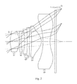
FIG. 2 is the light ray structural diagram of the camera lens system shown in FIG. 1;
FIG. 3 is the longitudinal spherical aberration, astigmatic field curves and distortion of the camera lens system shown in FIG. 1;
FIG. 4 is MTF curve diagram of the camera lens system shown in FIG. 1.
Description of the reference numbers in the drawings;
G1: The first lens group G2: The second lens group
G3: The third lens group G4: The fourth lens group
G5: The fifth lens group
L1: The first lens L2: The second lens
L3: The third lens L4: The fourth lens
L5: The fifth lens L6: The sixth lens
R2, R3, . . . : The curvature radius of the aperture, lens and optical
filter.
D1, D2, . . . : Distance from the aperture, lens and optical filter; the
center thickness of the aperture, lens and optical filter.
DETAILED DESCRIPTION OF THE EXEMPLARY EMBODIMENT
The present invention will hereinafter be described in detail with reference to an exemplary embodiment. It should be understood the specific embodiment described hereby is only to explain this disclosure, not intended to limit this disclosure.
Referring to the figures, the present invention provides a camera lens system. The camera lens system 10 shown in FIGS. 1-2 is an exemplary embodiment of the present invention. The camera lens system 10 includes 5 lens groups lined up from the object side to the image side surface: an aperture St, a first lens group G1, a second lens group G2, a third lens group G3, a fourth lens group G4 and a fifth lens group G5. An optical filter Lf and other optical materials are contained between the fifth lens group G5 and the image side surface Si.
The first lens group G1 includes a first lens L1. The second lens group G2 includes a second lens L2. The third lens group G3 includes a third lens L3 and a fourth lens L4. The fourth lens group G4 includes a fifth lens L5. The fifth lens group G5 includes a sixth lens L6.
The first lens L1 has a positive refractive power and its object side surface is outwardly convex. In this embodiment, the first lens L1 is a biconvex lens.
The second lens L2 has a negative refractive power. The object side surface is outwardly convex and the image side surface is inwardly concave.
The third lens L3 has a positive refractive power. The object side surface of the third lens L3 is convex and the image side surface is convex.
The fourth lens L4 has a negative refractive power. The image side surface of the third lens L3 is connected to the object side surface of the fourth lens L4. The object side surface of the fourth lens L4 is concave and the image side surface is concave.
In this embodiment, a contact surface between the third lens L3 and the fourth lens L4 is sphere, i.e. the third lens and the fourth lens are connected by a spherical face. It is easier to produce and process the lens and can also reduce the spherical aberration, astigmatism and distortion aberration.
According to the present invention, the first lens L1 is a biconvex lens. Therefore, the first lens is easy to process. At the same time, the second lens L2 has a negative refractive power and can reduce the light length. The principal light to the peripheral areas can be gathered and enhanced. In addition, the contact surface between the third lens L3 and the fourth lens L4 is a spherical face, thereby reducing the difficult degree in precision machining.
The image side surface of the fifth lens L5 is convex and has a positive refractive power. In this embodiment, the object side surface of the fifth lens L5 is outwardly convex.
The sixth lens L6 has a negative refractive power. The image side surface of the sixth lens L6 is concave and the object side surface is concave.
In particular, the image side surface of the sixth lens L6 has inflection point. The image side surface of the sixth lens L6 is concave at the area close to the optical axis and is convex at the area far away the optical axis. Thus the incident angle of principal light to the image side surface is reduced, thereby reducing spherical aberration and astigmatism, and improving the resolution of the lens.
The object side surface of the sixth lens L6 has also inflection point, i.e. the object side surface of the sixth lens L6 is concave at the area close to the optical axis and is convex at the area far away the optical axis.
The aperture St and the object side surface of the first lens L1 are located at the same position. It not only reduces total length of the camera lens system, but also reduces the external diameter of the lens, realizing the small size purpose.
In this embodiment, the image side surface of the first lens L1 is outwardly convex and the object side surface of the second lens L2 is inwardly concave. The image side surface of the third lens L3 is convex and the object side surface of the fourth lens L4 is concave. The interaction of adjacent convex and concave lenses can reduce the entire length of the camera lens system.
Specifically, f is the effective focal length of all lenses and f23 is the synthetic effective focal length of the second lens group G2 and the third lens group G3, thereby satisfying the following condition (1):
−5.0<f23/f<0  (1)
The condition (1) above influences maximally the image astigmatism and keeps the optical total length minimal. When f23/f is smaller than 0, the incident light of all wavelength toward the image side surface is substantially away the focal position, and astigmatism occurs, as a result, the image quality is reduced. When f23/f is more than 0, the refractive index of the incident light is reduced, and the distance from the object side surface of the first lens group G1 to the image side surface becomes longer, it is difficult to gather light.
Further, the first lens satisfies the following condition (2):
0.80<TTL/2y<0.95  (2)
Here, TTL is the distance from the object side surface to the image side surface of the first lens and y is the height of the maximal image on the image side surface, i.e. half of the length of diagonal line on the image surface sensor, so 2y is the length of the diagonal line of the image side surface sensor.
When TTL/2y is more than 0.95, total optical length increases. The optical system cannot be reduced. In addition, when TTL/2y is smaller than 0.80, the refractive index of the lens will be too large, it is not easy to correct the astigmatism of the second lens group and the third lens group, and therefore cannot get a high-performance camera lens system.
The third lens L3 and the fourth lens L4 form the third lens group G3. The third lens L3 has positive refractive power and the fourth lens L4 has negative refractive power. Therefore, the chromatic aberration of the third lens L3 is corrected by the fourth lens L4 which has negative refractive power.
In this embodiment, Vd_L3 represents Abbe number of the third lens and Vd_L4 represents Abbe number of the fourth lens. In this case, the third lens and the fourth lens satisfy the following condition (3):
20<Vd_L4−Vd_L3<40  (3)
In the condition (3) above, if Vd_L4−Vd_L3 are lower than 20, the focal length increases and the field-depth becomes small. The image curvature and chromatic astigmatism become larger. If Vd_L4−Vd_L3 is more than 40, the spherical astigmatism and chromatic astigmatism become large, the optical total length increases also.
Further, the second lens L2 and the third lens L3 satisfy the following condition (4) and condition (5):
20<Vd_L3<30  (4)
50<Vd_L4<60  (5)
Accordingly, the contrast difference shall be reduced, so the color spots are reduced.
The definition of the aspherical surface derived from the example of the present invention is as follows.
According to the lens of the present invention, the aspherical surface takes the optical axis direction as z-axis, the direction perpendicular to the optical axis as h axis, and the advancing direction of the light as the positive direction, so the following formula 1 is derived. In which, z represents the distance from the center optical axis to the vertical plane of aspherical vertex of aspheric coordinate point in the height of R. a1 is the conic constant and c is the reciprocal of the curvature radius of the lens vertex. a4, a6, a8, a10, a12, a14, a16 represent aspherical coefficients.
Z = CR 2 ( 1 + 1 - ( a 1 + 1 ) C 2 R 2 + a 4 r 4 + a 6 r 6 + a 8 r 8 + a 10 r 10 + a 12 r 12 + a 14 r 14 + a 16 r 16 R = X 2 + Y 2 , C = 1 / radius [ Formula 1 ]
The following illustrates the design data of the camera lens system according to the present invention. Table 1 shows the data of the camera lens system 10 shown in FIG. 1. Table 2 shows the aspherical data. Table 1 shows the curvature radius in FIG. 1 as R2, R3, . . . ; The thickness or distance shown in FIG. 1 is D1, D2, . . . . Since the aperture and the object side surface of the lens are located at the same position, the distance D1 between the aperture and the object side surface of the first lens 1 is taken as 0 in table 1.
TABLE 1
The radius of
Example 1 curvature Thickness nd vd
object Sphere Infinity Infinity
1 Sphere Infinity 0.00000
2 Asphere 2.63110 1.17800 1.5350 56.0000
3 Asphere −6.90326 0.10964
4 Asphere 34.99065 0.33645 1.6355 23.9000
5 Asphere 3.63086 0.40936
6 Asphere 1874.94728 0.52973 1.6410 22.4000
7 Sphere −43.44204 0.51360 1.5350 56.0000
8 Asphere 6.82184 0.18912
9 Asphere 24.93245 1.22190 1.5311 55.7000
10 Asphere −1.23506 0.12472
11 Asphere −16.38877 0.68069 1.5311 55.7000
12 Asphere 1.27514 0.53711
13 Sphere Infinity 0.21000 1.5167 64.2000
14 Sphere Infinity 0.93967
image Sphere Infinity 0.00000
TABLE
Aspheric coefficient
Conic constant 4 times factor 6 times factor 8 times factor 10 times factor 12 times factor
(k) (A) (B) (C) (D) (E) 14 factor (F)
2 −1.868443E+00 7.341124E−03 −1.585812E−03 −1.576121E−03 3.575346E−04 −4.428032E−04 0.000000E+00
3 −1.148948E+01 1.182757E−02 −3.421934E−02 1.365419E−02 −3.7557G8E−03 3.727034E−04 0.000000E+00
4 −3.000000E+02 1.116211E−02 −2.402887E−02 8.424336E−03 −7.982841E−04 1.487648E−04 0.000000E+00
6 −2.349287E+01 4.297803E−02 −2.362055E−02 1.004673E−02 −1.588893E−03 2.131244E−04 0.000000E+00
7 1.737030E+06 −3.196582E−02 3.035265E−03 7.922524E−03 −9.002978E−03 4.095363E−03 −6.451810E−04
8 −2.466167E+02 −9.754903E−03 5.575318E−05 −2.644260E−04 −3.787555E−05 1.3830606-05 1.191041E−05
9 −1.629865E+04 −3.604748E−02 3.264748E−02 −1.576299E−02 3.870090E−03 −4.719942E−04 1.772396E−05
10 −4.018201E+00 −2.028819E−02 4.841431E−03 9.304465E−04 −3.577614E−04 5.208556E−05 −4.874324E−06
11 −9.486423E+02 −3.720525E−02 2.384817E−03 4.236311E−04 −3.232133E−05 −1.709920E−06 1.516215E−07
12 −5.915792E+00 −2.999400E−02 6.494257E−03 −1.189164E−03 1.385557E−04 −9.159728E−06 2.537665E−07
FIG. 3 is the schematic diagram of the longitudinal spherical aberration, astigmatism field curve and distortion of middle and small camera lens system 10 shown in FIG. 1.
The longitudinal spherical aberration diagram shows the light with wavelength of about 65 nm, 587 nm, 486 nm and 435 nm. The astigmatism field curve and distortion indicate the light with the wavelength of 546 nm.
Table 3 below lists the values of all conditions in this embodiment. Obviously, the camera lens system of this embodiment satisfies the following conditions.
TABLE 3
Conditions Example
0.80 < TTL/2y < 0.95 0.889
20 < Vd_L3 < 30 22.4
50 < Vd_L4 < 60 56.0
FIG. 4 shows the schematic diagram of MTF resolving power of the camera lens system shown in FIG. 1. In FIG. 4, X-axis represents the spatial frequency and Y-axis represents the modulation.
It is to be understood, however, that even though numerous characteristics and advantages of the present embodiment have been set forth in the foregoing description, together with details of the structures and functions of the embodiment, the disclosure is illustrative only, and changes may be made in detail, especially in matters of shape, size, and arrangement of parts within the principles of the invention to the full extent indicated by the broad general meaning of the terms in which the appended claims are expressed.

Claims (5)

What is claimed is:
1. A camera lens system comprising five lens groups lined up from the object side, the lens groups including:
a first lens group comprising a first lens having a positive refractive power;
a second lens group comprising a second lens having a negative refractive power;
a third lens group comprising a third lens having a positive refractive power and a fourth lens having a negative refractive power, an image side surface of the third lens being cemented to an object side surface of the fourth lens;
a fourth lens group comprising a fifth lens having a convex image side surface and a positive refractive power;
a fifth lens group comprising a sixth lens having a concave image side surface and a negative refractive power;
the third lens and the fourth lens satisfying the following condition:

20<Vd_L4−Vd_L3<40
where, Vd_L3 is Abbe number of the third lens and Vd_L4 is Abbe number of the fourth lens.
2. The camera lens system according to claim 1 satisfying the following condition:

−5.0<f2.3/f<0
where,
f is the effective focal length of the entire lenses;
f23 is the synthetic effective focal length of the second lens group and the third lens group.
3. The camera lens system according to claim 1 satisfying the following condition:

0.80<TTL/2y<0.95
where
TTL is the distance from the object side surface of the first lens to the image side surface of the camera lens system;
y is half of the diagonal line length of the image side surface of the camera lens system.
4. The camera lens system according to claim 1, wherein the third lens and the fourth lens satisfy following condition:

20<Vd_L3<30

50<Vd_L4<60
where, Vd_L3 is Abbe number of the third lens and Vd_L4 is Abbe number of the fourth lens.
5. The camera lens system according to claim 1, wherein a cementing surface of the third lens and the fourth lens is spherical.
US15/011,485 2015-03-11 2016-01-30 Camera lens system Active 2036-04-06 US9835824B2 (en)

Applications Claiming Priority (2)

Application Number Priority Date Filing Date Title
KR1020150033974A KR101882990B1 (en) 2015-03-11 2015-03-11 Imaging Lens System
KR10-2015-0033974 2015-03-11

Publications (2)

Publication Number Publication Date
US20160266355A1 US20160266355A1 (en) 2016-09-15
US9835824B2 true US9835824B2 (en) 2017-12-05

Family

ID=54031009

Family Applications (1)

Application Number Title Priority Date Filing Date
US15/011,485 Active 2036-04-06 US9835824B2 (en) 2015-03-11 2016-01-30 Camera lens system

Country Status (3)

Country Link
US (1) US9835824B2 (en)
KR (1) KR101882990B1 (en)
CN (1) CN104898257B (en)

Cited By (1)

* Cited by examiner, † Cited by third party
Publication number Priority date Publication date Assignee Title
US9958650B1 (en) * 2016-11-02 2018-05-01 Genius Electronic Optical (Xiamen) Co., Ltd. Optical lens set

Families Citing this family (10)

* Cited by examiner, † Cited by third party
Publication number Priority date Publication date Assignee Title
CN105278081B (en) * 2015-07-07 2017-12-19 瑞声声学科技(深圳)有限公司 Pick-up lens
CN106526796B (en) * 2016-08-05 2019-09-24 玉晶光电(厦门)有限公司 Optical mirror slip group
CN107436477B (en) * 2017-09-07 2022-10-28 浙江舜宇光学有限公司 Optical imaging lens
TWI703367B (en) * 2018-02-08 2020-09-01 先進光電科技股份有限公司 Optical image capturing system
CN108873261B (en) * 2018-08-02 2021-01-22 诚瑞光学(苏州)有限公司 Image pickup optical lens
KR102139492B1 (en) * 2018-11-27 2020-07-29 엘컴텍 주식회사 Lens optical system
CN109375348A (en) * 2018-12-24 2019-02-22 浙江舜宇光学有限公司 Optical imaging system
CN109856779B (en) * 2018-12-31 2021-07-30 瑞声光学解决方案私人有限公司 Image pickup optical lens
CN110221408B (en) * 2019-06-29 2021-08-17 瑞声光学解决方案私人有限公司 Image pickup optical lens
CN111338060B (en) * 2020-05-21 2020-08-18 江西联益光学有限公司 Optical lens and imaging apparatus

Citations (2)

* Cited by examiner, † Cited by third party
Publication number Priority date Publication date Assignee Title
US3586418A (en) * 1968-03-27 1971-06-22 Minolta Camera Kk Wide-angle eyepiece lens system
US20140111872A1 (en) * 2012-10-22 2014-04-24 Largan Precision Co., Ltd. Optical photographing system

Family Cites Families (13)

* Cited by examiner, † Cited by third party
Publication number Priority date Publication date Assignee Title
JPH0850238A (en) * 1994-06-01 1996-02-20 Nikon Corp Wide angle lens
KR0135553B1 (en) 1995-06-22 1998-05-15 정몽원 Semiconductor type acceleration detecting device
JP2002162562A (en) * 2000-11-27 2002-06-07 Casio Comput Co Ltd Photographic lens
KR100800309B1 (en) 2006-05-26 2008-02-01 마루엘에스아이 주식회사 Ultraviolet sensor, readout circuit for ultravilet sensor and image sensor including ultraviolet sensor
JP2012155223A (en) 2011-01-27 2012-08-16 Tamron Co Ltd Wide-angle single-focus lens
TWI432772B (en) * 2011-06-10 2014-04-01 Largan Precision Co Ltd Optical image capturing lens assembly
TWI435138B (en) * 2011-06-20 2014-04-21 Largan Precision Co Optical imaging system for pickup
JP5853522B2 (en) 2011-09-14 2016-02-09 株式会社リコー Imaging lens, camera, and portable information terminal
KR101452045B1 (en) 2012-10-25 2014-10-21 삼성전기주식회사 Optical System
JP2014115431A (en) 2012-12-07 2014-06-26 Konica Minolta Inc Imaging lens, imaging apparatus, and portable terminal
JP6300183B2 (en) * 2013-04-22 2018-03-28 コニカミノルタ株式会社 Imaging lens, imaging device, and portable terminal
JP2014240918A (en) 2013-06-12 2014-12-25 富士フイルム株式会社 Imaging lens and imaging apparatus including imaging lens
CN203350521U (en) * 2013-06-28 2013-12-18 东莞市宇瞳光学科技有限公司 8mm wide-aperture day and night fixed focal lenses

Patent Citations (2)

* Cited by examiner, † Cited by third party
Publication number Priority date Publication date Assignee Title
US3586418A (en) * 1968-03-27 1971-06-22 Minolta Camera Kk Wide-angle eyepiece lens system
US20140111872A1 (en) * 2012-10-22 2014-04-24 Largan Precision Co., Ltd. Optical photographing system

Cited By (1)

* Cited by examiner, † Cited by third party
Publication number Priority date Publication date Assignee Title
US9958650B1 (en) * 2016-11-02 2018-05-01 Genius Electronic Optical (Xiamen) Co., Ltd. Optical lens set

Also Published As

Publication number Publication date
KR20160110747A (en) 2016-09-22
CN104898257B (en) 2017-07-18
CN104898257A (en) 2015-09-09
US20160266355A1 (en) 2016-09-15
KR101882990B1 (en) 2018-07-30

Similar Documents

Publication Publication Date Title
US9835824B2 (en) Camera lens system
US10215966B2 (en) Optical image lens system
US20230358999A1 (en) Photographing system, image capturing unit and electronic device
US10338348B2 (en) Optical image capturing lens system
US9612423B2 (en) Camera lens system
US9557530B2 (en) Photographing optical lens assembly, image capturing unit and mobile device
US9341820B2 (en) Image capturing optical system, image capturing device and electronic device
US8395691B2 (en) Optical image-capturing lens assembly
US8462449B2 (en) Optical lens assembly
US10976523B2 (en) Optical imaging lens assembly
US8089704B2 (en) Imaging lens assembly
US20140320981A1 (en) Photographing lens assembly
US10101561B2 (en) Five-piece optical imaging lens
US11119296B2 (en) Imaging optical lens assembly, image capturing unit and electronic device
US20110157449A1 (en) Photographing Lens Assembly
US11650398B2 (en) Camera lens assembly
US9354429B2 (en) Optical imaging lens
US20170184816A1 (en) Optical imaging lens
US9823449B1 (en) Optical telephoto imaging lens
US20190121063A1 (en) Optical imaging lens assembly
CN113156612B (en) Optical system, image capturing module and electronic equipment

Legal Events

Date Code Title Description
AS Assignment

Owner name: AAC ACOUSTIC TECHNOLOGIES (SHENZHEN)CO.,LTD, CHINA

Free format text: ASSIGNMENT OF ASSIGNORS INTEREST;ASSIGNORS:JANG, ISSAC;PARK, JAY;REEL/FRAME:039980/0345

Effective date: 20160129

STCF Information on status: patent grant

Free format text: PATENTED CASE

AS Assignment

Owner name: AAC COMMUNICATION TECHNOLOGIES (CHANGZHOU) CO., LTD., CHINA

Free format text: ASSIGNMENT OF ASSIGNORS INTEREST;ASSIGNOR:AAC ACOUSTIC TECHNOLOGIES (SHENZHEN) CO., LTD.;REEL/FRAME:052410/0333

Effective date: 20200311

AS Assignment

Owner name: AAC OPTICS (CHANGZHOU) CO., LTD., CHINA

Free format text: CHANGE OF NAME;ASSIGNOR:AAC COMMUNICATION TECHNOLOGIES (CHANGZHOU) CO., LTD.;REEL/FRAME:054090/0347

Effective date: 20200927

MAFP Maintenance fee payment

Free format text: PAYMENT OF MAINTENANCE FEE, 4TH YEAR, LARGE ENTITY (ORIGINAL EVENT CODE: M1551); ENTITY STATUS OF PATENT OWNER: LARGE ENTITY

Year of fee payment: 4