US9815058B2 - Fractionation of particles - Google Patents
Fractionation of particles Download PDFInfo
- Publication number
- US9815058B2 US9815058B2 US10/554,937 US55493704A US9815058B2 US 9815058 B2 US9815058 B2 US 9815058B2 US 55493704 A US55493704 A US 55493704A US 9815058 B2 US9815058 B2 US 9815058B2
- Authority
- US
- United States
- Prior art keywords
- lattice
- optical
- particles
- wells
- linked
- Prior art date
- Legal status (The legal status is an assumption and is not a legal conclusion. Google has not performed a legal analysis and makes no representation as to the accuracy of the status listed.)
- Active, expires
Links
- 239000002245 particle Substances 0.000 title claims abstract description 115
- 238000005194 fractionation Methods 0.000 title claims abstract description 26
- 230000003287 optical effect Effects 0.000 claims abstract description 98
- 238000000034 method Methods 0.000 claims description 27
- 239000012530 fluid Substances 0.000 claims description 21
- VYPSYNLAJGMNEJ-UHFFFAOYSA-N Silicium dioxide Chemical compound O=[Si]=O VYPSYNLAJGMNEJ-UHFFFAOYSA-N 0.000 description 24
- 229920000642 polymer Polymers 0.000 description 14
- 238000000926 separation method Methods 0.000 description 12
- 239000000377 silicon dioxide Substances 0.000 description 12
- 230000004888 barrier function Effects 0.000 description 6
- 239000000203 mixture Substances 0.000 description 6
- 102000004169 proteins and genes Human genes 0.000 description 6
- 108090000623 proteins and genes Proteins 0.000 description 6
- 210000004027 cell Anatomy 0.000 description 5
- 238000010586 diagram Methods 0.000 description 5
- 239000000499 gel Substances 0.000 description 5
- 230000003993 interaction Effects 0.000 description 5
- 238000012576 optical tweezer Methods 0.000 description 5
- 239000003094 microcapsule Substances 0.000 description 4
- 230000007935 neutral effect Effects 0.000 description 4
- 230000005855 radiation Effects 0.000 description 4
- 230000008901 benefit Effects 0.000 description 3
- RKTYLMNFRDHKIL-UHFFFAOYSA-N copper;5,10,15,20-tetraphenylporphyrin-22,24-diide Chemical compound [Cu+2].C1=CC(C(=C2C=CC([N-]2)=C(C=2C=CC=CC=2)C=2C=CC(N=2)=C(C=2C=CC=CC=2)C2=CC=C3[N-]2)C=2C=CC=CC=2)=NC1=C3C1=CC=CC=C1 RKTYLMNFRDHKIL-UHFFFAOYSA-N 0.000 description 3
- 210000003743 erythrocyte Anatomy 0.000 description 3
- 238000002474 experimental method Methods 0.000 description 3
- 210000004698 lymphocyte Anatomy 0.000 description 3
- 239000000463 material Substances 0.000 description 3
- 238000012552 review Methods 0.000 description 3
- 239000012798 spherical particle Substances 0.000 description 3
- 238000013459 approach Methods 0.000 description 2
- 210000000349 chromosome Anatomy 0.000 description 2
- 230000000694 effects Effects 0.000 description 2
- 238000002955 isolation Methods 0.000 description 2
- 230000000704 physical effect Effects 0.000 description 2
- 239000012491 analyte Substances 0.000 description 1
- 238000004458 analytical method Methods 0.000 description 1
- 230000015572 biosynthetic process Effects 0.000 description 1
- 238000005251 capillar electrophoresis Methods 0.000 description 1
- 239000002775 capsule Substances 0.000 description 1
- 210000000170 cell membrane Anatomy 0.000 description 1
- 230000008859 change Effects 0.000 description 1
- 230000005465 channeling Effects 0.000 description 1
- 230000000295 complement effect Effects 0.000 description 1
- 230000003247 decreasing effect Effects 0.000 description 1
- 230000001419 dependent effect Effects 0.000 description 1
- 238000013461 design Methods 0.000 description 1
- 230000004069 differentiation Effects 0.000 description 1
- 238000009792 diffusion process Methods 0.000 description 1
- 238000012377 drug delivery Methods 0.000 description 1
- 239000002961 echo contrast media Substances 0.000 description 1
- 238000001962 electrophoresis Methods 0.000 description 1
- 238000001502 gel electrophoresis Methods 0.000 description 1
- 230000036512 infertility Effects 0.000 description 1
- 230000010354 integration Effects 0.000 description 1
- 238000000651 laser trapping Methods 0.000 description 1
- 230000004807 localization Effects 0.000 description 1
- 229920002521 macromolecule Polymers 0.000 description 1
- 230000007246 mechanism Effects 0.000 description 1
- 239000004005 microsphere Substances 0.000 description 1
- 238000012986 modification Methods 0.000 description 1
- 230000004048 modification Effects 0.000 description 1
- 238000012544 monitoring process Methods 0.000 description 1
- 238000000917 particle-image velocimetry Methods 0.000 description 1
- 239000011860 particles by size Substances 0.000 description 1
- 239000012466 permeate Substances 0.000 description 1
- 239000011148 porous material Substances 0.000 description 1
- 238000012805 post-processing Methods 0.000 description 1
- 238000005381 potential energy Methods 0.000 description 1
- 230000008569 process Effects 0.000 description 1
- 238000012545 processing Methods 0.000 description 1
- 239000000047 product Substances 0.000 description 1
- 238000011084 recovery Methods 0.000 description 1
- 230000009467 reduction Effects 0.000 description 1
- 238000012216 screening Methods 0.000 description 1
- 230000035945 sensitivity Effects 0.000 description 1
- 239000002356 single layer Substances 0.000 description 1
- 230000003068 static effect Effects 0.000 description 1
- 239000000725 suspension Substances 0.000 description 1
- 238000001890 transfection Methods 0.000 description 1
- 230000007704 transition Effects 0.000 description 1
- 239000013598 vector Substances 0.000 description 1
Images


Classifications
-
- B—PERFORMING OPERATIONS; TRANSPORTING
- B01—PHYSICAL OR CHEMICAL PROCESSES OR APPARATUS IN GENERAL
- B01L—CHEMICAL OR PHYSICAL LABORATORY APPARATUS FOR GENERAL USE
- B01L3/00—Containers or dishes for laboratory use, e.g. laboratory glassware; Droppers
- B01L3/50—Containers for the purpose of retaining a material to be analysed, e.g. test tubes
- B01L3/502—Containers for the purpose of retaining a material to be analysed, e.g. test tubes with fluid transport, e.g. in multi-compartment structures
- B01L3/5027—Containers for the purpose of retaining a material to be analysed, e.g. test tubes with fluid transport, e.g. in multi-compartment structures by integrated microfluidic structures, i.e. dimensions of channels and chambers are such that surface tension forces are important, e.g. lab-on-a-chip
- B01L3/502753—Containers for the purpose of retaining a material to be analysed, e.g. test tubes with fluid transport, e.g. in multi-compartment structures by integrated microfluidic structures, i.e. dimensions of channels and chambers are such that surface tension forces are important, e.g. lab-on-a-chip characterised by bulk separation arrangements on lab-on-a-chip devices, e.g. for filtration or centrifugation
-
- B—PERFORMING OPERATIONS; TRANSPORTING
- B01—PHYSICAL OR CHEMICAL PROCESSES OR APPARATUS IN GENERAL
- B01L—CHEMICAL OR PHYSICAL LABORATORY APPARATUS FOR GENERAL USE
- B01L3/00—Containers or dishes for laboratory use, e.g. laboratory glassware; Droppers
- B01L3/50—Containers for the purpose of retaining a material to be analysed, e.g. test tubes
- B01L3/502—Containers for the purpose of retaining a material to be analysed, e.g. test tubes with fluid transport, e.g. in multi-compartment structures
- B01L3/5027—Containers for the purpose of retaining a material to be analysed, e.g. test tubes with fluid transport, e.g. in multi-compartment structures by integrated microfluidic structures, i.e. dimensions of channels and chambers are such that surface tension forces are important, e.g. lab-on-a-chip
- B01L3/502761—Containers for the purpose of retaining a material to be analysed, e.g. test tubes with fluid transport, e.g. in multi-compartment structures by integrated microfluidic structures, i.e. dimensions of channels and chambers are such that surface tension forces are important, e.g. lab-on-a-chip specially adapted for handling suspended solids or molecules independently from the bulk fluid flow, e.g. for trapping or sorting beads, for physically stretching molecules
-
- B—PERFORMING OPERATIONS; TRANSPORTING
- B01—PHYSICAL OR CHEMICAL PROCESSES OR APPARATUS IN GENERAL
- B01D—SEPARATION
- B01D15/00—Separating processes involving the treatment of liquids with solid sorbents; Apparatus therefor
- B01D15/08—Selective adsorption, e.g. chromatography
- B01D15/26—Selective adsorption, e.g. chromatography characterised by the separation mechanism
- B01D15/38—Selective adsorption, e.g. chromatography characterised by the separation mechanism involving specific interaction not covered by one or more of groups B01D15/265 - B01D15/36
- B01D2015/3895—Selective adsorption, e.g. chromatography characterised by the separation mechanism involving specific interaction not covered by one or more of groups B01D15/265 - B01D15/36 using light
-
- B—PERFORMING OPERATIONS; TRANSPORTING
- B01—PHYSICAL OR CHEMICAL PROCESSES OR APPARATUS IN GENERAL
- B01L—CHEMICAL OR PHYSICAL LABORATORY APPARATUS FOR GENERAL USE
- B01L2200/00—Solutions for specific problems relating to chemical or physical laboratory apparatus
- B01L2200/06—Fluid handling related problems
- B01L2200/0647—Handling flowable solids, e.g. microscopic beads, cells, particles
-
- B—PERFORMING OPERATIONS; TRANSPORTING
- B01—PHYSICAL OR CHEMICAL PROCESSES OR APPARATUS IN GENERAL
- B01L—CHEMICAL OR PHYSICAL LABORATORY APPARATUS FOR GENERAL USE
- B01L2300/00—Additional constructional details
- B01L2300/08—Geometry, shape and general structure
- B01L2300/0861—Configuration of multiple channels and/or chambers in a single devices
- B01L2300/0864—Configuration of multiple channels and/or chambers in a single devices comprising only one inlet and multiple receiving wells, e.g. for separation, splitting
-
- B—PERFORMING OPERATIONS; TRANSPORTING
- B01—PHYSICAL OR CHEMICAL PROCESSES OR APPARATUS IN GENERAL
- B01L—CHEMICAL OR PHYSICAL LABORATORY APPARATUS FOR GENERAL USE
- B01L2400/00—Moving or stopping fluids
- B01L2400/04—Moving fluids with specific forces or mechanical means
- B01L2400/0403—Moving fluids with specific forces or mechanical means specific forces
- B01L2400/0454—Moving fluids with specific forces or mechanical means specific forces radiation pressure, optical tweezers
-
- G—PHYSICS
- G01—MEASURING; TESTING
- G01N—INVESTIGATING OR ANALYSING MATERIALS BY DETERMINING THEIR CHEMICAL OR PHYSICAL PROPERTIES
- G01N15/00—Investigating characteristics of particles; Investigating permeability, pore-volume or surface-area of porous materials
- G01N15/10—Investigating individual particles
- G01N15/14—Optical investigation techniques, e.g. flow cytometry
- G01N15/1434—Optical arrangements
-
- G—PHYSICS
- G01—MEASURING; TESTING
- G01N—INVESTIGATING OR ANALYSING MATERIALS BY DETERMINING THEIR CHEMICAL OR PHYSICAL PROPERTIES
- G01N15/00—Investigating characteristics of particles; Investigating permeability, pore-volume or surface-area of porous materials
- G01N15/10—Investigating individual particles
- G01N15/14—Optical investigation techniques, e.g. flow cytometry
- G01N15/1456—Optical investigation techniques, e.g. flow cytometry without spatial resolution of the texture or inner structure of the particle, e.g. processing of pulse signals
- G01N15/1459—Optical investigation techniques, e.g. flow cytometry without spatial resolution of the texture or inner structure of the particle, e.g. processing of pulse signals the analysis being performed on a sample stream
-
- G—PHYSICS
- G01—MEASURING; TESTING
- G01N—INVESTIGATING OR ANALYSING MATERIALS BY DETERMINING THEIR CHEMICAL OR PHYSICAL PROPERTIES
- G01N15/00—Investigating characteristics of particles; Investigating permeability, pore-volume or surface-area of porous materials
- G01N15/10—Investigating individual particles
- G01N15/14—Optical investigation techniques, e.g. flow cytometry
- G01N15/149—Optical investigation techniques, e.g. flow cytometry specially adapted for sorting particles, e.g. by their size or optical properties
-
- G—PHYSICS
- G01—MEASURING; TESTING
- G01N—INVESTIGATING OR ANALYSING MATERIALS BY DETERMINING THEIR CHEMICAL OR PHYSICAL PROPERTIES
- G01N15/00—Investigating characteristics of particles; Investigating permeability, pore-volume or surface-area of porous materials
- G01N15/10—Investigating individual particles
- G01N15/14—Optical investigation techniques, e.g. flow cytometry
- G01N15/1434—Optical arrangements
- G01N2015/1447—Spatial selection
- G01N2015/145—Spatial selection by pattern of light, e.g. fringe pattern
-
- G01N2015/149—
-
- G—PHYSICS
- G01—MEASURING; TESTING
- G01N—INVESTIGATING OR ANALYSING MATERIALS BY DETERMINING THEIR CHEMICAL OR PHYSICAL PROPERTIES
- G01N30/00—Investigating or analysing materials by separation into components using adsorption, absorption or similar phenomena or using ion-exchange, e.g. chromatography or field flow fractionation
- G01N30/02—Column chromatography
Definitions
- the present invention relates to a system and method for separating or fractionating particles according to one or more physical criteria.
- the same system can be used to insert particles into another flow stream (a form of mixing).
- fractionation schemes exist, ranging from gel-electrophoresis, capillary electrophoresis, and analytical centrifuging to novel, entropic barriers. Examples of these are described by J. Han, H. G. Craighead, Science 288, 1026-1029 (May 12, 2000) and D. Nykypanchuk, H. H. Strey, D. A. Hoagland, Science 297, 987-990 (Aug. 9, 2002).
- the majority of these known techniques separate a polydisperse mixture into bands containing particles that travel at different velocities along the direction of flow. This typically leads to batch processing.
- electrophoresis a gel may be used to obtain a size-dependent mobility. Recovery of fractions is achieved through post-processing of the gel. However, despite its widespread use and effectiveness this methodology is slow and importantly, due to limited pore sizes, has difficulty in separating objects at the microscopic size level, for example cells, chromosomes, and colloidal matter.
- Lithographically fabricated two-dimensional, asymmetric artificial gels are also used. Examples of these are described in the articles by D. Ertas, Physical Review Letters 80, 1548-1551 (Feb. 16, 1998); T. A. J. Duke, R. H. Austin, Physical Review Letters 80, 1552-1555 (Feb. 16, 1998) and C. F. Chou et al., Biophysical Journal 83, 2170-2179 (October, 2002). These gels yield separation transverse to the direction of flow. Because of this, they can be operated in a continuous fashion, with various fractions taken up by separate collection channels. However, sorting based on diffusion becomes impractically slow at the microscopic scale and above.
- Fractionation systems are used in many different applications.
- One field where their use is becoming of increasing interest is that of microfluidics.
- flow is predominantly laminar, creating challenges in the design of actuators such as mixers and sorters.
- actuators such as mixers and sorters.
- the ability to select and sort both colloidal and biological matter in a manner related to its physical properties in a fast and efficient manner is a key requirement at this level.
- An object of the present invention is to provide an improved system and method for separating or fractionating particles.
- a fractionation system comprising means for forming an optical lattice having a plurality of linked potential wells.
- the potential wells are linked in such a manner that the lattice is asymmetric.
- the lattice has stronger connectivity along one direction than along another direction. This allows deflection in a single direction, which is a key requirement for useful deflection.
- the wells in one lattice direction may be strongly linked and wells in another direction may be substantially unlinked.
- strongly linked it is meant that the light intensity pattern in the said one lattice direction has peaks and troughs, wherein the intensity in a trough does not dip below approximately one third of the intensity at a peak.
- wells in one lattice direction may be completely linked and wells in another direction may be substantially unlinked.
- completely linked it is meant that there are substantially no troughs in the intensity pattern in the said one lattice direction.
- the wells may be linked to make possible a deflection in a range of 0 degrees to 85 degrees.
- the deflection angle may be 45 degrees of more.
- a fractionation system comprising means for forming a three dimensional optical lattice.
- optical lattice is meant an intensity-modulated extended light pattern.
- the optical lattice has a plurality of linked potential wells.
- the wells may be linked in such a manner as to provide a deflection of 45 degrees or more
- a method for optimizing fractionation of particles comprising tuning an optical lattice, preferably a three dimensional optical lattice, and/or varying particle flow rate through the lattice until optimum conditions are reached.
- tuning the optical lattice it is meant varying characteristics of the beams that are used to define the lattice, such as beam intensity or lattice constant.
- a method for fractionating particles comprising forming an optical lattice that has a plurality of linked potential wells and is defined so as to cause deflection of particles as a function of a pre-determined characteristic, such as size or refractive index or shape, and causing relative movement between a fluid that contains the particles that are to be separated and the lattice.
- the method involves causing a fluid flow through the lattice.
- the method may involve scanning the lattice through the fluid.
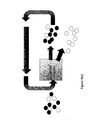
- FIG. 1 is a block diagram of a system for fractionating particles using an optical lattice
- FIG. 2 is a schematic diagram of a system for defining an optical lattice in the system of FIG. 1 ;
- FIG. 3( a ) is a false-colour intensity map and two scans for an optical lattice in which discrete traps are defined;
- FIG. 3( b ) is a false-colour intensity map and two scans for an optical lattice in which weakly linked traps are defined;
- FIG. 3( c ) is a false-colour intensity map and two scans for an optical lattice in which extended guides are defined;
- FIG. 4( a ) is a view of a silica/polymer mix
- FIG. 4( b ) is view of the trajectories traced by the particles of the mix of FIG. 4( a ) as they move through a three dimensional optical lattice;
- FIG. 4( c ) is a separate view of the trajectory for the polymer
- FIG. 4( d ) is a separate view of the trajectory for the silica
- FIG. 4( e ) indicates that the throughput can be increased without cost to efficiency by increasing the laser power as flow speed is increased;
- FIG. 5 is a plot showing experimental results for various different lattice types
- FIG. 6 is view of the trajectories traced by the particles of another poly disperse mix as they move through a three dimensional optical lattice
- FIG. 7 is a diagram illustrating tagged sorting
- FIG. 8 is a view showing the separation of a single erythrocyte from a flow of lymphocytes.
- FIG. 9( a ) is a schematic diagram illustrating re-circulated separation
- FIG. 9( b ) is a schematic diagram illustrating cascaded separation
- FIG. 1 shows a micro-fluidic system for fractionating particles.
- This has a fractionation chamber 2 and means (not shown) for defining an optical lattice within that chamber 2 .
- Connected to the fractionation chamber 2 by suitable fluid passages are four chambers A, B, C and D. Fluid can flow between chamber A and chambers C and D via the fractionation chamber. Likewise, fluid can flow between chamber B and chambers C and D via the fractionation chamber 2 .
- chamber B includes a poly-disperse fluid that includes two different particle types. Chamber A would typically introduce a “blank” flowstream, though this could be any stream into which the selected particles are to be introduced.
- the optical lattice is created using a multi-beam interference pattern that forms a tailored 3D potential energy landscape, which causes micro-objects to be deflected in a desired manner.
- the optical lattice is three dimensional in nature allowing the ability to sort particles throughout a three-dimensional flow.
- the interaction between the optical lattice and matter causes selected particle types to follow described paths through the lattice, thereby providing optical fractionation.
- the optical lattice is adapted to direct one set of the particles that originate from chamber B into chamber C and the other particles into chamber D. In this case one set of particles is deflected by the optical lattice, whereas the other set is largely unaffected.
- the optical lattice which is a modulated pattern of light, is not limited to the visible wavelengths of light.
- FIG. 2 A specific example of a suitable arrangement is shown in FIG. 2 .
- This has a diffractive-optic (DOE) beamsplitter 10 that splits a laser beam into four first-order beams 12 plus the remaining zero-order beam 14 in the centre of a cross shape.
- An aperture is provided to remove higher order beams.
- Light from the DOE 10 is directed into a first lens 16 .
- This is positioned so that its output comprises five parallel beams, that is the four first order beams 12 and the single zero order beam 14 .
- neutral density filters 18 In the optical path of the first order beams are provided neutral density filters 18 . These reduce the intensity of the first-order beams so that stronger linkage between intensity maxima of the multi-beam interference pattern can be obtained.
- the neutral density filters 18 may each have a power of 0.3D.
- coverslip slivers 20 Downstream from the neutral density filters 18 are coverslip slivers 20 , which can be used to change the effective path length of a beam without introducing significant deflection.
- a mirror 22 On the optical path from the coverslips 20 is a mirror 22 that turns the light about ninety degrees onto another lens 24 , which focuses the light towards another mirror 26 .
- Light reflected from the mirror 26 is directed towards another lens 28 , which is positioned so as to provide an input having four parallel first order beams and a zeroth order beam to an optical tweezer arrangement 30 .
- Optical tweezer arrangements are generally adapted to hold particles within potential wells. However, for the purposes of the present invention, trapping of particles is undesirable.
- an optical tweezer arrangement 30 can be used to define a lattice of discrete sites, here it is adapted so that optical gradient forces and/or radiation pressure can be effective to deflect particles moving through an extended lattice.
- optical gradient forces and/or radiation pressure can be effective to deflect particles moving through an extended lattice.
- the lattice that is used is not an array of optical tweezers.
- FIG. 2 it is possible to generate a 3D optical lattice, in particular a body-centred tetragonal lattice, using a five-beam interference pattern.
- the fractionation system of FIG. 1 is based on the fact that a particle can be deflected when it moves within an optical lattice, because of the spatial variation of the radiation field.
- the energy reduction, U which occurs when a dielectric particle sits at particular point in the optical lattice, (as opposed to a point far outside of the laser beam) can be found by integrating the product of the relative polarizability and the local energy density, ⁇ , over the volume V of the particle:
- the local trapping potential is a function of the polarizability of the particle material as compared to that of the surrounding medium, the local intensity of the lattice and particle size.
- the interaction grows as the third power of the radius allowing for fractionation of particles by size.
- the interaction strength depends upon the specific relation of the particle size to the lattice parameters of the optical lattice.
- the lattice parameters can be tuned to remove any size dependence (over some range of particle sizes), thereby allowing selection based purely on index of refraction. This sort of tunable selection criteria is a key feature of the method.
- ⁇ is the viscosity of the fluid containing the particles
- r is the radius of the particle
- ⁇ is the velocity of the fluid flow.
- a high deflection angle is desirable.
- some degree of optical connectivity between adjacent nodes of the lattice is important. By this is meant that the potential wells are not separated in all directions by high barriers. To achieve this, the distribution of light intensity is sculpted accordingly. In this way, barrier heights can easily be reduced along one direction with respect to another by tuning the relative intensity or phase of the beams forming the lattice.
- FIG. 3 shows various false-colour intensity maps and intensity line scans for optical lattices that have different barrier heights between the lattice maxima.
- FIG. 3( a ) shows a lattice in which the interference maxima have equal intensity in the zeroth-order and total first-order, giving discrete, well-separated intensity maxima, almost completely unlinked in any direction.
- FIG. 3( b ) shows an intensity map and two line scans for the situation where a neutral density filter of 3D is used on the first-order beams to introduce strong linkage along the [ 100 ] direction, whilst maintaining strong isolation along the [ 110 ] direction.
- the lattice used is asymmetric, that is there is stronger connectivity along one diagonal than along the opposite diagonal.
- FIG. 3( c ) shows an intensity map and two line scans for the situation where two diagonally opposite first-order beams are completely removed to yield complete linkage along the [ 100 ] direction while, again, maintaining isolation along the [ 110 ] direction.
- These fringes also exist along the z-axis, such that the line maxima, that is rods of high intensity, lie in a log-pile formation, so that they form a triangular lattice of extended optical guides. Again, this results in an asymmetric lattice, but in this case, there is no linkage in one direction and complete linkage in the other, thought this might not be the case for all situations. In practice, optimal performance can be found with the pattern shown in FIG. 3( b ) .
- FIG. 4 shows polymer and silica spheres co-flowing from right to left through a body-centered tetragonal optical lattice.
- the size of the silica and polymer spheres is the same, (and hence their Stoke's force is the same), but the optical forces exerted upon a polymer sphere is greater, due to its higher relative polarisability.
- the fluid speed was 30 ⁇ m/s, with a total incident laser power of 530 mW.
- the optical lattice was such that there was a stronger linkage between intensity maxima along the [ 100 ] direction than those along the [ 010 ] direction. This linkage encourages selected particles to follow the [ 100 ] direction instead of the [ 010 ] direction, as less force is required to move a particle between intensity peaks in the [ 100 ] direction.
- FIG. 4( a ) is an image of the silica/polymer mix, indicating the typical particle density.
- the polymer has a relatively lower density than the silica. Differences in contrast allow each particle to be tracked separately using particle image velocimetry.
- FIG. 4( b ) shows various trajectories for the mix of FIG. 4( a ) , with a circle indicating the xy range over which the optical lattice is most intense. From this it can be seen that co-flowing particles can be separated using the optical lattice. The estimated throughput of the system was about 25 particles per second.
- the trajectories for the polymer and silica are shown separately in FIGS. 4( c ) and 4( d ) respectively.
- the polymer tracks show a deflection of approximately 45 degrees. This very large angular separation can be attributed to the linking of intensity maxima along the [ 100 ] direction of the optical lattice.
- the polymer spheres nearly all enter the field of view only once they reach the strongest part of the optical lattice.
- the lower density of the polymer spheres means that they normally flow away from the bottom surface of the sample cell, but are subsequently guided into the focal plane of monitoring optics by the optical forces. Once in the focal plane, all of the polymer spheres move along the [ 100 ] direction, and none along the [ 010 ].
- the silica tracks are only slightly modulated by the optical lattice.
- the silica spheres all enter the field of view at the right edge and move in approximately straight lines, except in the mid-left portion of the field of view, where they are deflected to and fro (slightly) by the strongest part of the lattice, with no net deflection resulting.
- the silica and polymer spheres can be separated, because of the differences in the polarisabilities of the two materials, which causes the spheres to interact with the lattice in different ways.
- FIG. 4( e ) indicates that the throughput can be increased without cost to efficiency by increasing the laser power (and hence ⁇ U) as flow speed is increased.
- ⁇ U the laser power
- the particle flow speed is increased or laser power is decreased or particle size or relative polarizability is changed, a crossover is observed from strongly trapped to hopping behaviour to guided flow. This can be further tuned from pseudo-ballistic to diffusively guided regimes, and—finally—to the limit where all particles flow past unhindered.
- a spread in angular deflections (fractionation) results for any suspension containing a broad distribution of sizes.
- particle-particle interactions become significant (either as a function of screening length or density)
- the de-pinning transition can take on a collective, many-body character. At speeds just beyond de-pinning, both species are deflected by the optical lattice. By appropriately selecting the particle speeds/laser power optimal separation can be achieved.
- the extended guides give the highest flow velocity, but the BCT lattice has a lower error rate with no particles of species B being deflected above 10 microns/s. It is noticeable that in a situation where large angle deflections are not critical it is possible to operate at much lower laser powers for the same flow velocity. However use of such lower angles requires longer lattices and increases the probability of many-body effects reducing the performance of the system.
- Particles can also be separated according to size. Separation according to size has also been demonstrated experimentally using both silica spheres and low index particles.
- black crosses 32 represent positions of two 2- ⁇ m diameter protein microcapsules as they flow from right to left across the optical lattice. Again, significant angular deflection is achieved, while a co-flowing 4- ⁇ m diameter capsule of the same sort flows nearly straight through, as shown by the dots 34 . In this case, the flow speed is 20 ⁇ m/s with a total incident power of 530 mW. This allows the creation of a monodisperse collection of protein microcapsules. These protein microcapsules are an ultrasound contrast agent that can be used to locally permeate cell membranes.
- tagged sorting can be used.
- tagged helper particles are used such as streptavadin or antibody coated microspheres to select a specific particle species that can then be separated using an optical lattice.
- FIG. 7 shows a diagrammatic representation of this technique using chromosomes.
- the methodology in which the invention is embodied is particularly useful for sorting cells and DNA. These can be sorted in the same manner as other particles, that is: by their physical properties such as size, shape or refractive index.
- the sorting of erythrocytes from lymphocytes is shown in FIG. 8 . This shows a single erythrocyte being selectively guided through the optical lattice as the rest of the cells in the flow (lymphocytes) pass straight through unhindered. Separation of macromolecules such as DNA and proteins can take place directly in the lattice, through the use of tagged spheres as outlined above or where such tags do not exist to use one of the techniques described below (E).
- a key feature of the methodology is its non-invasive nature and the accompanying ability to sort particles without any physical contact in the system whatsoever.
- the method is reconfigurable such that its selection criteria can be tuned in real time.
- sole use of optical forces simplifies surface interaction and sterility issues by removing the extremely high surface area associated with any physical sieve or gel. Efficiency can approach 100%, with values of 96% or more observed even at the upper-limit of the semi-dilute regime. This can be achieved without the need to expose analytes to high electrical charge, and whilst avoiding the introduction of further material surfaces as would be associated with microfabricated sieves. This simplifies the lithographic requirements of the sample cells.
- the invention does not require the use of unreliable micro-constrictions, thereby reducing the likelihood of blockages or clogs.
- a yet further advantage is that by using an optical lattice, the need to tag particles that are to be separated can be avoided, although as described previously tagging can be used as and when desired for additional functionality. Also, there is no need for the particles to have different fluorescences.
- the method in which the invention is embodied enables the separation of particles that have sizes that differ by less than 20%. This increases the practicality of the technique, allowing it to be used for many different applications.
- the technique can be integrated into existing microscopes or used as a stand-alone device. It is also ideally suited to integration into other sorting techniques based on micro-flows to give complementary sorting properties or to be incorporated into a larger micro-total analysis system.
- the analyte can be either re-circulated through the optical lattice as illustrated in FIG. 9( a ) or directed through cascaded separation chambers as illustrated in FIG. 9( b ) .
- An advantage of this latter option is that it allows for the employment of multiple selection criteria in a single integrated chip.
- the description has focused on sorting by size or type of particle, it is possible to use the invention to sort particles according to their shape. This is because different shapes of particles will interact more or less strongly with the optical lattice such that particles can also be sorted by shape.
- An example is that a cylindrical object will interact more completely (due to its aligning with the lattice) with an lattice of extended guides than a spherical particle hence making it possible to sort cylindrical particles from spherical particles.
- optical lattices can be generalised to the case of an optical landscape (an optical pattern either 2D or 3D with or without rotational or mirror symmetry).
- the pattern including the optical lattice
- the pattern can be scanned dynamically such that the selective movement of particles is provided by the movement of the lattice (movement and scanning in this case means not the movement of the entire pattern but rather the movement of the features of the pattern such that a particle follows for example a light maxima that travels across the area of the pattern).
- movement and scanning in this case means not the movement of the entire pattern but rather the movement of the features of the pattern such that a particle follows for example a light maxima that travels across the area of the pattern).
- the movement of a particle depends critically on the relative speed of the landscape versus the Kramer's time i.e.
Landscapes
- Chemical & Material Sciences (AREA)
- Health & Medical Sciences (AREA)
- Clinical Laboratory Science (AREA)
- Chemical Kinetics & Catalysis (AREA)
- Dispersion Chemistry (AREA)
- Analytical Chemistry (AREA)
- General Health & Medical Sciences (AREA)
- Hematology (AREA)
- Life Sciences & Earth Sciences (AREA)
- Molecular Biology (AREA)
- Physics & Mathematics (AREA)
- Fluid Mechanics (AREA)
- Apparatus Associated With Microorganisms And Enzymes (AREA)
- Physical Or Chemical Processes And Apparatus (AREA)
- Investigating Or Analysing Biological Materials (AREA)
- Separation Of Solids By Using Liquids Or Pneumatic Power (AREA)
- Micro-Organisms Or Cultivation Processes Thereof (AREA)
Applications Claiming Priority (5)
| Application Number | Priority Date | Filing Date | Title |
|---|---|---|---|
| GB0310497.3 | 2003-05-08 | ||
| GB0310497A GB0310497D0 (en) | 2003-05-08 | 2003-05-08 | Fractionation of microfluidic particle streams in an optical lattice |
| GB0314269.2 | 2003-06-19 | ||
| GB0314269A GB0314269D0 (en) | 2003-06-19 | 2003-06-19 | Fractionation of particles |
| PCT/GB2004/001993 WO2004100175A1 (fr) | 2003-05-08 | 2004-05-07 | Fractionnement de particules |
Publications (2)
| Publication Number | Publication Date |
|---|---|
| US20070091442A1 US20070091442A1 (en) | 2007-04-26 |
| US9815058B2 true US9815058B2 (en) | 2017-11-14 |
Family
ID=33436276
Family Applications (1)
| Application Number | Title | Priority Date | Filing Date |
|---|---|---|---|
| US10/554,937 Active 2028-05-22 US9815058B2 (en) | 2003-05-08 | 2004-05-07 | Fractionation of particles |
Country Status (5)
| Country | Link |
|---|---|
| US (1) | US9815058B2 (fr) |
| EP (1) | EP1620862B1 (fr) |
| CA (1) | CA2524646C (fr) |
| ES (1) | ES2544944T3 (fr) |
| WO (1) | WO2004100175A1 (fr) |
Families Citing this family (20)
| Publication number | Priority date | Publication date | Assignee | Title |
|---|---|---|---|---|
| US9815058B2 (en) | 2003-05-08 | 2017-11-14 | The University Court Of The University Of St Andrews | Fractionation of particles |
| US7473890B2 (en) * | 2004-11-23 | 2009-01-06 | New York University | Manipulation of objects in potential energy landscapes |
| US7586684B2 (en) * | 2005-01-21 | 2009-09-08 | New York University | Solute characterization by optoelectronkinetic potentiometry in an inclined array of optical traps |
| GB0518273D0 (en) * | 2005-09-08 | 2005-10-19 | Univ Dundee | Apparatus and method for sonoporation |
| GB0618606D0 (en) | 2006-09-21 | 2006-11-01 | Univ St Andrews | Optical sorting |
| GB0618605D0 (en) | 2006-09-21 | 2006-11-01 | Univ St Andrews | Optical sorting |
| US7847238B2 (en) | 2006-11-07 | 2010-12-07 | New York University | Holographic microfabrication and characterization system for soft matter and biological systems |
| US7676122B2 (en) * | 2006-12-11 | 2010-03-09 | Jiahua James Dou | Apparatus, system and method for particle manipulation using waveguides |
| US8174742B2 (en) | 2008-03-14 | 2012-05-08 | New York University | System for applying optical forces from phase gradients |
| EP2387708B1 (fr) | 2009-01-16 | 2019-05-01 | New York University | Caractérisation de particules en temps réel automatisée et vélocimétrie tridimensionnelle avec microscopie vidéo holographique |
| CN102753954A (zh) * | 2009-12-22 | 2012-10-24 | 纽约大学 | 利用光学力将胶粒分成多个通道:棱镜光学分离 |
| EP2906928A4 (fr) | 2012-10-15 | 2016-11-09 | Nanocellect Biomedical Inc | Systèmes, appareil et procédés de tri de particules |
| DK3218690T3 (da) | 2014-11-12 | 2022-05-02 | Univ New York | Kolloidt fingeraftryk til bløde materialer med brug af total holografisk karakterisation |
| US10737012B2 (en) | 2015-03-31 | 2020-08-11 | Biomet Biologics, Inc. | Cell washing using acoustic waves |
| US9855382B2 (en) * | 2015-03-31 | 2018-01-02 | Biomet Biologics, Llc | Cell washing device using standing acoustic waves and a phantom material |
| WO2017139279A2 (fr) | 2016-02-08 | 2017-08-17 | New York University | Caractérisation holographique d'agrégats de protéines |
| CN109331893B (zh) * | 2018-11-22 | 2021-07-23 | 复旦大学 | 微流控自由流纸色谱阵列喷雾质谱联用装置 |
| US11360016B2 (en) * | 2019-06-13 | 2022-06-14 | The Regents Of The University Of California | Plasmofluidic microlenses for label-free optical sorting of bioparticles |
| US11543338B2 (en) | 2019-10-25 | 2023-01-03 | New York University | Holographic characterization of irregular particles |
| US11948302B2 (en) | 2020-03-09 | 2024-04-02 | New York University | Automated holographic video microscopy assay |
Citations (41)
| Publication number | Priority date | Publication date | Assignee | Title |
|---|---|---|---|---|
| US3710279A (en) * | 1969-12-15 | 1973-01-09 | Bell Telephone Labor Inc | Apparatuses for trapping and accelerating neutral particles |
| US3808550A (en) * | 1969-12-15 | 1974-04-30 | Bell Telephone Labor Inc | Apparatuses for trapping and accelerating neutral particles |
| US4523682A (en) * | 1982-05-19 | 1985-06-18 | The United States Of America As Represented By The Administrator Of The National Aeronautics And Space Administration | Acoustic particle separation |
| US5158889A (en) | 1988-12-22 | 1992-10-27 | Omron Corporation | Biological cell sorter |
| JPH0526799A (ja) | 1991-07-19 | 1993-02-02 | Nippon Steel Corp | 微粒子の分離方法 |
| US5245466A (en) | 1990-08-15 | 1993-09-14 | President And Fellows Of Harvard University And Rowland Institute | Optical matter |
| WO1998010267A1 (fr) | 1996-09-04 | 1998-03-12 | Technical University Of Denmark | Systeme a microdebit pour separation et analyse de particules |
| US5938904A (en) * | 1996-03-27 | 1999-08-17 | Curagen Corporation | Separation of charged particles by a spatially and temporally varying electric field |
| US6216538B1 (en) * | 1992-12-02 | 2001-04-17 | Hitachi, Ltd. | Particle handling apparatus for handling particles in fluid by acoustic radiation pressure |
| DE19952322A1 (de) | 1999-10-29 | 2001-05-17 | Evotec Biosystems Ag | Verfahren und Vorrichtung zur Partikeltrennung |
| US6416190B1 (en) | 2001-04-27 | 2002-07-09 | University Of Chicago | Apparatus for using optical tweezers to manipulate materials |
| WO2002084276A1 (fr) | 2001-04-11 | 2002-10-24 | The Regents Of The University Of Michigan | Dispositifs et prodedes de separation de particules |
| US20020160470A1 (en) | 2000-11-13 | 2002-10-31 | Genoptix | Methods and apparatus for generating and utilizing linear moving optical gradients |
| US20020185592A1 (en) | 2001-06-06 | 2002-12-12 | Grier David G. | Optical peristaltic pumping with optical traps |
| US20030007894A1 (en) | 2001-04-27 | 2003-01-09 | Genoptix | Methods and apparatus for use of optical forces for identification, characterization and/or sorting of particles |
| US20030047676A1 (en) | 2001-09-13 | 2003-03-13 | Grier David G. | Apparatus and process for the lateral deflection and separation of flowing particles by a static array of optical tweezers |
| US6548124B1 (en) * | 2000-03-20 | 2003-04-15 | Paul Brumer | Nanometric scale coherently controlled molecular deposition |
| US20030111594A1 (en) | 2001-12-13 | 2003-06-19 | Commissariat A L'energie Atomique | Optical device and optical process for particle displacement |
| US20030132373A1 (en) * | 2002-01-16 | 2003-07-17 | Curtis Jennifer E. | Use of multiple optical vortices for pumping, mixing and sorting |
| CA2493411A1 (fr) | 2002-07-31 | 2004-02-05 | Arryx, Inc. | Systeme et procede de tri de materiau utilisant une orientation par laser holographique |
| US20040021949A1 (en) | 2002-08-01 | 2004-02-05 | The University Of Chicago | Apparatus and method for fabricating, sorting, and integrating materials with holographic optical traps |
| US20040067167A1 (en) | 2002-10-08 | 2004-04-08 | Genoptix, Inc. | Methods and apparatus for optophoretic diagnosis of cells and particles |
| WO2004082840A1 (fr) | 2003-03-17 | 2004-09-30 | Evotec Oai Ag | Procedes et dispositifs pour separer des particules dans un ecoulement de liquide |
| WO2004100175A1 (fr) | 2003-05-08 | 2004-11-18 | The University Court Of The University Of St Andrews | Fractionnement de particules |
| US6833542B2 (en) | 2000-11-13 | 2004-12-21 | Genoptix, Inc. | Method for sorting particles |
| WO2005054818A1 (fr) | 2003-12-04 | 2005-06-16 | Commissariat A L'energie Atomique | Dispositif de separation d'objets faisant appel a un procede optique |
| WO2005054832A1 (fr) | 2003-12-04 | 2005-06-16 | Commissariat A L'energie Atomique | Procede de tri de particules |
| US20050247866A1 (en) | 2003-10-28 | 2005-11-10 | Joseph Plewa | System and method for manipulating and processing materials using holographic optical trapping |
| US6974927B2 (en) | 2002-03-26 | 2005-12-13 | Intel Corporation | Method and system for optically sorting and/or manipulating carbon nanotubes |
| WO2006004558A1 (fr) | 2004-07-06 | 2006-01-12 | Agency For Science, Technology And Research | Puce a adn destinee a trier et lyser des echantillons biologiques |
| WO2006032844A2 (fr) | 2004-09-23 | 2006-03-30 | The University Court Of The University Of St Andrews | Tri de particules dans un motif sur mesure |
| WO2006059084A1 (fr) | 2004-11-30 | 2006-06-08 | The University Court Of The University Of St Andrews | Photoporation de cellules |
| US20060177940A1 (en) | 2005-02-07 | 2006-08-10 | Furst Eric M | Optical trap separations in microfluidic flows |
| US7161140B2 (en) * | 2002-04-10 | 2007-01-09 | Arryx, Inc. | Apparatus and method to generate and control optical traps to manipulate small particles |
| US7351953B2 (en) | 2003-04-10 | 2008-04-01 | Arryx, Inc. | Apparatus and method to generate and control optical traps to manipulate small particles |
| US20090188795A1 (en) | 2002-02-04 | 2009-07-30 | Colorado School Of Mines | Cell sorting device and method of manufacturing the same |
| US7612355B2 (en) | 2004-04-12 | 2009-11-03 | The Regents Of The University Of California | Optoelectronic tweezers for microparticle and cell manipulation |
| US20100047761A1 (en) | 2006-09-21 | 2010-02-25 | Macdonald Michael | Capillary transport |
| US7732758B2 (en) | 2004-05-12 | 2010-06-08 | The University Court Of The University Of St. Andrews | Optoelectronic tweezers |
| US8298727B2 (en) | 2005-01-21 | 2012-10-30 | New York University | Multi-color holographic optical trapping |
| US8816234B2 (en) | 2006-09-21 | 2014-08-26 | The University Court Of The University Of St. Andrews | Acousto-optic sorting |
-
2004
- 2004-05-07 US US10/554,937 patent/US9815058B2/en active Active
- 2004-05-07 ES ES04731667.4T patent/ES2544944T3/es not_active Expired - Lifetime
- 2004-05-07 EP EP04731667.4A patent/EP1620862B1/fr not_active Expired - Lifetime
- 2004-05-07 WO PCT/GB2004/001993 patent/WO2004100175A1/fr active Application Filing
- 2004-05-07 CA CA2524646A patent/CA2524646C/fr not_active Expired - Lifetime
Patent Citations (47)
| Publication number | Priority date | Publication date | Assignee | Title |
|---|---|---|---|---|
| US3808550A (en) * | 1969-12-15 | 1974-04-30 | Bell Telephone Labor Inc | Apparatuses for trapping and accelerating neutral particles |
| US3710279A (en) * | 1969-12-15 | 1973-01-09 | Bell Telephone Labor Inc | Apparatuses for trapping and accelerating neutral particles |
| US4523682A (en) * | 1982-05-19 | 1985-06-18 | The United States Of America As Represented By The Administrator Of The National Aeronautics And Space Administration | Acoustic particle separation |
| US5158889A (en) | 1988-12-22 | 1992-10-27 | Omron Corporation | Biological cell sorter |
| US5245466A (en) | 1990-08-15 | 1993-09-14 | President And Fellows Of Harvard University And Rowland Institute | Optical matter |
| JPH0526799A (ja) | 1991-07-19 | 1993-02-02 | Nippon Steel Corp | 微粒子の分離方法 |
| US6216538B1 (en) * | 1992-12-02 | 2001-04-17 | Hitachi, Ltd. | Particle handling apparatus for handling particles in fluid by acoustic radiation pressure |
| US5938904A (en) * | 1996-03-27 | 1999-08-17 | Curagen Corporation | Separation of charged particles by a spatially and temporally varying electric field |
| WO1998010267A1 (fr) | 1996-09-04 | 1998-03-12 | Technical University Of Denmark | Systeme a microdebit pour separation et analyse de particules |
| DE19952322A1 (de) | 1999-10-29 | 2001-05-17 | Evotec Biosystems Ag | Verfahren und Vorrichtung zur Partikeltrennung |
| US6548124B1 (en) * | 2000-03-20 | 2003-04-15 | Paul Brumer | Nanometric scale coherently controlled molecular deposition |
| US20020160470A1 (en) | 2000-11-13 | 2002-10-31 | Genoptix | Methods and apparatus for generating and utilizing linear moving optical gradients |
| US6833542B2 (en) | 2000-11-13 | 2004-12-21 | Genoptix, Inc. | Method for sorting particles |
| WO2002084276A1 (fr) | 2001-04-11 | 2002-10-24 | The Regents Of The University Of Michigan | Dispositifs et prodedes de separation de particules |
| WO2002087792A8 (fr) | 2001-04-27 | 2003-11-20 | Genoptix Inc | Procedes et dispositif d'utilisation de forces optiques pour l'identification, la caracterisation et/ou le tri de particules |
| US20030007894A1 (en) | 2001-04-27 | 2003-01-09 | Genoptix | Methods and apparatus for use of optical forces for identification, characterization and/or sorting of particles |
| US6416190B1 (en) | 2001-04-27 | 2002-07-09 | University Of Chicago | Apparatus for using optical tweezers to manipulate materials |
| US20020185592A1 (en) | 2001-06-06 | 2002-12-12 | Grier David G. | Optical peristaltic pumping with optical traps |
| US20030047676A1 (en) | 2001-09-13 | 2003-03-13 | Grier David G. | Apparatus and process for the lateral deflection and separation of flowing particles by a static array of optical tweezers |
| US20030111594A1 (en) | 2001-12-13 | 2003-06-19 | Commissariat A L'energie Atomique | Optical device and optical process for particle displacement |
| US20030132373A1 (en) * | 2002-01-16 | 2003-07-17 | Curtis Jennifer E. | Use of multiple optical vortices for pumping, mixing and sorting |
| WO2003062867A2 (fr) | 2002-01-17 | 2003-07-31 | Genoptix, Inc. | Procedes et appareil pour generer et utiliser des gradients optiques a deplacement lineaire |
| US20090188795A1 (en) | 2002-02-04 | 2009-07-30 | Colorado School Of Mines | Cell sorting device and method of manufacturing the same |
| US6974927B2 (en) | 2002-03-26 | 2005-12-13 | Intel Corporation | Method and system for optically sorting and/or manipulating carbon nanotubes |
| US7161140B2 (en) * | 2002-04-10 | 2007-01-09 | Arryx, Inc. | Apparatus and method to generate and control optical traps to manipulate small particles |
| WO2004012133A2 (fr) | 2002-07-31 | 2004-02-05 | Arryx, Inc. | Systeme et procede de tri de materiau utilisant une orientation par laser holographique |
| US20040089798A1 (en) | 2002-07-31 | 2004-05-13 | Lewis Gruber | System and method of sorting materials using holographic laser steering |
| CA2493411A1 (fr) | 2002-07-31 | 2004-02-05 | Arryx, Inc. | Systeme et procede de tri de materiau utilisant une orientation par laser holographique |
| US20040021949A1 (en) | 2002-08-01 | 2004-02-05 | The University Of Chicago | Apparatus and method for fabricating, sorting, and integrating materials with holographic optical traps |
| US20040067167A1 (en) | 2002-10-08 | 2004-04-08 | Genoptix, Inc. | Methods and apparatus for optophoretic diagnosis of cells and particles |
| WO2004082840A1 (fr) | 2003-03-17 | 2004-09-30 | Evotec Oai Ag | Procedes et dispositifs pour separer des particules dans un ecoulement de liquide |
| US7351953B2 (en) | 2003-04-10 | 2008-04-01 | Arryx, Inc. | Apparatus and method to generate and control optical traps to manipulate small particles |
| WO2004100175A1 (fr) | 2003-05-08 | 2004-11-18 | The University Court Of The University Of St Andrews | Fractionnement de particules |
| US20050247866A1 (en) | 2003-10-28 | 2005-11-10 | Joseph Plewa | System and method for manipulating and processing materials using holographic optical trapping |
| US7449679B2 (en) | 2003-10-28 | 2008-11-11 | Arryx, Inc. | System and method for manipulating and processing materials using holographic optical trapping |
| WO2005054818A1 (fr) | 2003-12-04 | 2005-06-16 | Commissariat A L'energie Atomique | Dispositif de separation d'objets faisant appel a un procede optique |
| WO2005054832A1 (fr) | 2003-12-04 | 2005-06-16 | Commissariat A L'energie Atomique | Procede de tri de particules |
| US7612355B2 (en) | 2004-04-12 | 2009-11-03 | The Regents Of The University Of California | Optoelectronic tweezers for microparticle and cell manipulation |
| USRE44711E1 (en) | 2004-04-12 | 2014-01-21 | The Regents Of The University Of California | Optoelectronic tweezers for microparticle and cell manipulation |
| US7732758B2 (en) | 2004-05-12 | 2010-06-08 | The University Court Of The University Of St. Andrews | Optoelectronic tweezers |
| WO2006004558A1 (fr) | 2004-07-06 | 2006-01-12 | Agency For Science, Technology And Research | Puce a adn destinee a trier et lyser des echantillons biologiques |
| WO2006032844A2 (fr) | 2004-09-23 | 2006-03-30 | The University Court Of The University Of St Andrews | Tri de particules dans un motif sur mesure |
| WO2006059084A1 (fr) | 2004-11-30 | 2006-06-08 | The University Court Of The University Of St Andrews | Photoporation de cellules |
| US8298727B2 (en) | 2005-01-21 | 2012-10-30 | New York University | Multi-color holographic optical trapping |
| US20060177940A1 (en) | 2005-02-07 | 2006-08-10 | Furst Eric M | Optical trap separations in microfluidic flows |
| US20100047761A1 (en) | 2006-09-21 | 2010-02-25 | Macdonald Michael | Capillary transport |
| US8816234B2 (en) | 2006-09-21 | 2014-08-26 | The University Court Of The University Of St. Andrews | Acousto-optic sorting |
Non-Patent Citations (29)
| Title |
|---|
| Chia-Fu Chou, Jonas O. Tegenfeldt, Olgica Bakajin, Shirley S. Chan, Edward C. Cox, Nicholas Darnton, Thomas Duke and Robert H. Austin; Electrodeless Dielectrophoresis of Single- and Double-Stranded DNA; Biophysical Journal; Oct. 2002; pp. 2170-2179; vol. 83; 2002 Bighysical Society. |
| Deniz Ertas; Lateral Separation of Macromolecules and Polyelectrolytes in Microlithographic Arrays; Physical Review Letters; Feb. 16, 1998; pp. 1548-1551; vol. 80, No. 7; 1998 The American Physical Society. |
| Dharmadhikari, et al., "Torque-generating Malaria-infected Red Blood Cells in an Optical Trap," Mar. 22, 2004, vol. 12, No. 6, Optics Express, pp. 1179-1184. |
| Dmytro Nykypanchuk, Helmut H. Strey and David A. Hoagland; Brownian Motion of DNA Confined Within a Two-Dimensional Array; Science; Aug. 9, 2002; pp. 987-990; vol. 297. |
| Eric R. Dufresne and David G. Grier; Optical Tweezer Arrays and Optical Substrates Created with Diffractive Optics; Review of Scientific Instruments; May 5, 1998; pp. 1974-1977; vol. 69, No. 5; 1998 American Institute of Physics. |
| International Search Report for PCT/GB2004/001993 dated Jul. 23, 2004. |
| International Search Reported dated Apr. 23, 2008, Application No. PCT/GB2007/003578, filed Sep. 20, 2007. |
| International Search Reported dated Jan. 7, 2008, for application PCT/GB2007/003573, filed Sep. 20, 2007. |
| J. Han and H.G. Craighead; Separation of Long DNA Molecules in a Microfabricated Entropic Trap Array; Science; May 12, 2000; pp. 1026-1029; vol. 288. |
| Jennifer E. Curtis, Brian A. Koss and David G. Grier; Dynamic Holographic Optical Tweezers; Optics Communications; Jun. 15, 2002; pp. 169-175; vol. 207; 2002 Elsevier Science B.V. |
| M.P. MacDonald, G.C. Spalding and K. Dholakia; Microfluidic Sorting in an Optical Lattice; Nature, Nov. 27, 2003; pp. 421-424; vol. 426; 2003 Nature Publishing Group (XP-002289740). |
| MACDONALD ET AL: "MICROFLUIDIC SORTING IN AN OPTICAL LATTICE", NATURE, MACMILLAN JOURNALS LTD., ETC, vol. 426, 27 November 2003 (2003-11-27), pages 421 - 424, XP002289740, ISSN: 0028-0836, DOI: 10.1038/nature02144 |
| Notice of Allowance dated Dec. 24, 2012, U.S. Appl. No. 12/442,325. |
| Office Action dated Apr. 27, 2009, Canadian Application No. 2,524,646. |
| Office Action dated Aug. 23, 2011, U.S. Appl. No. 12/442,325. |
| Office Action dated Dec. 6, 2012, U.S. Appl. No. 12/442,327. |
| Office Action dated Feb. 16, 2011, U.S. Appl. No. 12/442,325. |
| Office Action dated Feb. 8, 2010, Canadian Application No. 2,524,646. |
| Office Action dated Jul. 24, 2012, U.S. Appl. No. 12/442,325. |
| Office Action dated May 16, 2012, U.S. Appl. No. 12/442,327. |
| Padgett, et al.; "Optical Tweezers and Spanners," Physics World, Sep. 1997, pp. 35-38, IOP Publishing, Bristol Great Britain. |
| Padgett, et al.; "The Angular Momentum of Light: Optical Spanners and the Rotational Frequency Shift," Optical and Quantum Electronics, pp. 1-12, vol. 31, No. 1, Chapman and Hall, London, Great Britain,1999. |
| Pamela T. Korda, Michael B. Taylor and David G. Grier; Kinetically Locked-In Colloidal Transport in an Array of Optical Tweezers; Physical Review Letters; Sep. 16, 2002; pp. 128301-1-128301-4; vol. 89, No. 12; 2002 The American Physical Society. |
| Paterson, et al., "Light-induced Cell Separation in a Tailored Optical Landscape," Applied Physics Letters, Sep. 13, 2005, Article 123901, vol. 87. |
| Ramser, et al.; "A Microfluidic System Enabling Raman Measurements of the Oxygenation Cycle in Single Optically Trapped Red Blood Cells," Lab on a Chip, Feb. 21, 2005, pp. 431-436, No. 5, Royal Society of Chemistry, Cambridge, Great Britain. |
| Sancho, et al., "Reply" Physical Review Letters, May 12, 2005, Article 188902, vol. 94, The American Physical Society. |
| T.A.J. Duke and R.H. Austin; Microfabricated Sieve for the Continuous Sorting of Macromolecules; Physical Review Letters; Feb. 16, 1998; pp. 1552-1555; vol. 80, No. 7; 1998 The American Physical Society. |
| United States Patent and Trademark Office, Notice of Allowance and Fee(s) Due for U.S. Appl. No. 12/442,327, dated Nov. 6, 2014, 14 pages, USA. |
| United States Patent and Trademark Office, Office Action for U.S. Appl. No. 12/442,325, dated Feb. 7, 2014, 12 pages, USA. |
Also Published As
| Publication number | Publication date |
|---|---|
| CA2524646A1 (fr) | 2004-11-18 |
| WO2004100175A1 (fr) | 2004-11-18 |
| EP1620862B1 (fr) | 2015-07-08 |
| EP1620862A1 (fr) | 2006-02-01 |
| ES2544944T3 (es) | 2015-09-07 |
| CA2524646C (fr) | 2012-02-21 |
| US20070091442A1 (en) | 2007-04-26 |
Similar Documents
| Publication | Publication Date | Title |
|---|---|---|
| US9815058B2 (en) | Fractionation of particles | |
| US11415936B2 (en) | Multiple laminar flow-based particle and cellular separation with laser steering | |
| US9977401B2 (en) | Multiple laminar flow-based particle and cellular separation with laser steering | |
| US6797942B2 (en) | Apparatus and process for the lateral deflection and separation of flowing particles by a static array of optical tweezers | |
| US7751048B2 (en) | Optofluidic microscope device | |
| US7773227B2 (en) | Optofluidic microscope device featuring a body comprising a fluid channel and having light transmissive regions | |
| US7402131B2 (en) | Multiple laminar flow-based particle and cellular separation with laser steering | |
| EP1663460B1 (fr) | Separation des cellules et des particules basee sur flux laminaire multiple et guidage laser | |
| US9594071B2 (en) | Device and method for laser analysis and separation (LAS) of particles | |
| US20120273664A1 (en) | Sorting Colloidal Particles Into Multiple Channels with Optical Forces: Prismatic Optical Fractionation | |
| DE102008060332B4 (de) | Verfahren zum Sortieren von mindestens einem Partikel mit einer mikrofluidischen Sortiervorrichtung mit optischer Pinzette | |
| WO2006032844A2 (fr) | Tri de particules dans un motif sur mesure | |
| MacDonald et al. | Microfluidic optical sorting: particle selection in an optical lattice | |
| MacDonald et al. | Sorting via injection of particle streams into an optical lattice |
Legal Events
| Date | Code | Title | Description |
|---|---|---|---|
| AS | Assignment |
Owner name: THE UNIVERSITY COURT OF THE UNIVERSITY OF ST. ANDR Free format text: ASSIGNMENT OF ASSIGNORS INTEREST;ASSIGNORS:MACDONALD, MICHAEL PETER;DHOLAKIA, KISHAN;NEALE, STEVEN LEONARD;AND OTHERS;REEL/FRAME:018598/0059 Effective date: 20051129 |
|
| STCF | Information on status: patent grant |
Free format text: PATENTED CASE |
|
| MAFP | Maintenance fee payment |
Free format text: PAYMENT OF MAINTENANCE FEE, 4TH YEAR, LARGE ENTITY (ORIGINAL EVENT CODE: M1551); ENTITY STATUS OF PATENT OWNER: LARGE ENTITY Year of fee payment: 4 |
|
| FEPP | Fee payment procedure |
Free format text: ENTITY STATUS SET TO SMALL (ORIGINAL EVENT CODE: SMAL); ENTITY STATUS OF PATENT OWNER: SMALL ENTITY |