US9805926B2 - Vibration resistant automotive front lighting lamp - Google Patents
Vibration resistant automotive front lighting lamp Download PDFInfo
- Publication number
- US9805926B2 US9805926B2 US14/917,906 US201414917906A US9805926B2 US 9805926 B2 US9805926 B2 US 9805926B2 US 201414917906 A US201414917906 A US 201414917906A US 9805926 B2 US9805926 B2 US 9805926B2
- Authority
- US
- United States
- Prior art keywords
- filament
- baffle
- vessel
- holding wire
- lamp
- Prior art date
- Legal status (The legal status is an assumption and is not a legal conclusion. Google has not performed a legal analysis and makes no representation as to the accuracy of the status listed.)
- Expired - Fee Related, expires
Links
Images


Classifications
-
- H—ELECTRICITY
- H01—ELECTRIC ELEMENTS
- H01K—ELECTRIC INCANDESCENT LAMPS
- H01K1/00—Details
- H01K1/18—Mountings or supports for the incandescent body
-
- F—MECHANICAL ENGINEERING; LIGHTING; HEATING; WEAPONS; BLASTING
- F21—LIGHTING
- F21S—NON-PORTABLE LIGHTING DEVICES; SYSTEMS THEREOF; VEHICLE LIGHTING DEVICES SPECIALLY ADAPTED FOR VEHICLE EXTERIORS
- F21S41/00—Illuminating devices specially adapted for vehicle exteriors, e.g. headlamps
- F21S41/10—Illuminating devices specially adapted for vehicle exteriors, e.g. headlamps characterised by the light source
- F21S41/14—Illuminating devices specially adapted for vehicle exteriors, e.g. headlamps characterised by the light source characterised by the type of light source
- F21S41/162—Incandescent light sources, e.g. filament or halogen lamps
- F21S41/164—Incandescent light sources, e.g. filament or halogen lamps having two or more filaments
-
- F—MECHANICAL ENGINEERING; LIGHTING; HEATING; WEAPONS; BLASTING
- F21—LIGHTING
- F21S—NON-PORTABLE LIGHTING DEVICES; SYSTEMS THEREOF; VEHICLE LIGHTING DEVICES SPECIALLY ADAPTED FOR VEHICLE EXTERIORS
- F21S41/00—Illuminating devices specially adapted for vehicle exteriors, e.g. headlamps
- F21S41/10—Illuminating devices specially adapted for vehicle exteriors, e.g. headlamps characterised by the light source
- F21S41/19—Attachment of light sources or lamp holders
- F21S41/192—Details of lamp holders, terminals or connectors
-
- F21S48/1109—
-
- F21S48/1172—
-
- H—ELECTRICITY
- H01—ELECTRIC ELEMENTS
- H01K—ELECTRIC INCANDESCENT LAMPS
- H01K1/00—Details
- H01K1/28—Envelopes; Vessels
-
- H—ELECTRICITY
- H01—ELECTRIC ELEMENTS
- H01K—ELECTRIC INCANDESCENT LAMPS
- H01K3/00—Apparatus or processes adapted to the manufacture, installing, removal, or maintenance of incandescent lamps or parts thereof
- H01K3/06—Attaching of incandescent bodies to mount
-
- H—ELECTRICITY
- H01—ELECTRIC ELEMENTS
- H01K—ELECTRIC INCANDESCENT LAMPS
- H01K3/00—Apparatus or processes adapted to the manufacture, installing, removal, or maintenance of incandescent lamps or parts thereof
- H01K3/20—Sealing-in wires directly into the envelope
-
- H—ELECTRICITY
- H01—ELECTRIC ELEMENTS
- H01K—ELECTRIC INCANDESCENT LAMPS
- H01K9/00—Lamps having two or more incandescent bodies separately heated
- H01K9/08—Lamps having two or more incandescent bodies separately heated to provide selectively different light effects, e.g. for automobile headlamp
Definitions
- the invention relates to an electrical lamp, and in particular to a lamp for use in automotive vehicle front lighting, and to a method of manufacturing such a lamp.
- the invention further relates to a vehicle headlight.
- Automotive headlights i.e. headlights for use on board of a vehicle, such as e.g. a car, motorcycle, truck or other type of vehicle generally comprise a reflector and, mounted therein, a lamp.
- Known incandescent lamps, in particular halogen lamps generally comprise a base and a burner. The base provides mechanical and electrical connection to the automotive headlight, whereas the burner comprises the actual light-emitting element, in particular filament. Light emitted from the filament is reflected by the reflector to form a beam for illumination in front of the vehicle.
- incandescent lamps which comprise one or more filaments arranged within a vessel.
- a lamp according to claim 1 a vehicle headlight according to claim 9 and a manufacturing method according to claim 10 are proposed.
- Dependent claims refer to preferred embodiments.
- an automotive lamp i.e. a lamp for use on board of a vehicle which is resistant to vibration.
- lamps may be required that withstand strong vibration of several g.
- the present inventors have recognized that a lamp with a special vibration-resistant construction may still be easy to manufacture and maintain advantageous optical properties.
- a lamp according to an aspect of the invention comprises a base for mechanical and electrical connection to an automotive headlight. Electrical contacts may protrude out of the base, in particular from the rear thereof.
- the base further preferably comprises a positioning ring which serves for mounting the lamp in a reflector of a vehicle headlight in a defined position and orientation.
- the positioning ring may comprise radial protrusions, which may serve for mechanical fixing, and for exact positioning. It is in particular preferred to provide one reference protrusion to define a radial reference direction R.
- the lamp further comprises a burner with a sealed vessel, at least partially transparent, preferably of quartz glass.
- a first filament is arranged within the vessel.
- a second filament may be arranged within the vessel, provided at a distance from the first filament.
- the filaments are spaced along the longitudinal axis of the lamp, i.e. the axis extending centrally through the positioning ring.
- a baffle is arranged proximate to a first filament.
- the baffle may in particular be arranged to cover the axial range of the first filament, i.e. be arranged in radial directions of the first filament along the whole axial length thereof.
- a portion of the light emitted from the first filament, emitted into spatial directions of the proximate baffle, will be shaded by the baffle.
- At least one holding wire is arranged within the vessel.
- the holding wires may be fixed in a pinch seal of the vessel, and may project into its interior.
- One of the holding wires may serve to hold the baffle in its position proximate to the first filament.
- the baffle is fixed to the holding wire, preferably welded thereto. Further, the first and second filaments may be fixed to the holding wires.
- the transparent vessel comprises a vessel wall which includes a cylindrical portion surrounding at least the first filament.
- a deformed material portion is provided within the cylindrical portion of the vessel wall, where the otherwise cylindrical shape of the material of the vessel wall is deformed and may project into the interior of the otherwise cylindrical vessel.
- the deformed material portion at least contacts the baffle or the holding wire to which the baffle is fixed. This stabilizes the baffle and/or holding wire and therefore limits movement thereof in response to vibration.
- the contact may in principle be one-sided, i.e. such that the baffle and/or the holding wire simply lie adjacent to the deformed material portion of the vessel wall. Already this type of contact may serve to render the lamp more resistant to vibration.
- the contact between the deformed material portion and the baffle/holding wire is an adhering contact, such that even under the application of an external force by vibration, the baffle/holding wire will not separate from the deformed material portion of the vessel wall.
- the deformed material portion at least partially encloses the holding wire and/or the portion of the baffle to obtain a form-fitting contact securely anchoring the baffle and/or holding wire within the deformed material portion.
- the deformed material portion is arranged at a position where it is shielded from the first filament by the baffle.
- the baffle may include an inner side (facing the first filament) and an opposite outer side, and that the deformed material portion is arranged to contact the outer side, and/or the holding wire arranged at the outer side.
- Embodiments of the invention have in tests been shown to withstand mechanical shocks of up to 10 g.
- Optical distortion due to the deformed material portion which may e.g. be formed as a dimple of the material of the vessel wall, in particular quartz glass, is minimal if the deformed portion is arranged behind the baffle, as viewed from the first filament.
- the lamp is easy to manufacture and existing manufacturing processes may easily be modified to provide the deformed portion.
- the manufacturing method according to the invention it is preferred to provide the transparent vessel with the cylindrical portion of the vessel wall without the deformed portion, and to insert the baffle and holding wire before closing the vessel.
- the vessel wall may be deformed at the cylindrical portion to provide the deformed material portion at a position shielded from the first filament by the baffle. In particular, this may be done by heating the vessel wall at least up to a softening temperature, at least locally at the position of the deformed material portion to be formed.
- the deformation may be formed by gas pressure.
- the holding wire may comprise a free end, projecting from the fixing position of the holding wire to the baffle. This free end is well suited for contact between the deformed material portion and the holding wire.
- the deformed material portion at least partially encloses the free end of the holding wire to establish a form-fitting fixation.
- the deformed material portion is arranged at a position which is shielded not only from the first filament but also from the second filament by the baffle. This positioning may in particular be obtained by arranging the deformed material portion at a free projecting end of the holding wire. The deformed material portion is then arranged shaded from direct light by both filaments, such that optical distortion is further minimized.
- At least three holding wires are arranged to project into the interior of the vessel.
- the first filament preferably also a second filament and the baffle are fixed to the holding wires.
- a pinch seal is formed at a portion of the vessel, sealing the vessel and embedding the holding wires.
- the holding wires extend from the pinch seal into the interior of the vessel.
- a holding bar is arranged within the interior of the vessel, distant from the pinch seal.
- the holding bar serves to hold the holding wires, preferably by at least partially enclosing the wires within the material of the holding bar.
- the holding bar is preferably made out of glass. Regarding the manufacturing method, it is preferred to form the holding bar before inserting the holding wires into the vessel.
- the base comprises three electrical contacts, and three holding wires are arranged extending from a pinch seal into the interior of the vessel.
- Each of the holding wires is electrically connected to one of the electrical contacts.
- the first filament is electrically connected between a first and a third holding wire
- the second filament is electrically connected between a second and the third holding wire.
- the filaments share a common electrical connection.
- the first filament is not connected directly to the third holding wire, but electrical contact is established via the baffle fixed to the third holding wire.
- the baffle may be of concave shape, e.g. provided in one piece and made out of correspondingly shaped sheet metal, in particular molybdenum.
- a front surface of the baffle may be arranged at a front axial end of the baffle, preferably the end facing towards the base, arranged at least partially in between the filaments.
- the baffle may be effective to shield the second filament from light emitted from the first filament.
- the baffle thus serves to separate angular ranges illuminated by both filaments from angular ranges illuminated only by the second filament, where light emitted from the first filament is shaded at the baffle.
- Corresponding portions of the reflector may be shaped to reflect light emitted from the first filament—which may be denoted a low beam filament—into a first beam (low beam, comprising a bright/dark cutoff) and correspondingly reflect light emitted from the second filament (e.g. high-beam filament) into a reflected beam (high beam) without a bright/dark cutoff.
- a low beam filament into a first beam (low beam, comprising a bright/dark cutoff)
- the second filament e.g. high-beam filament
- the filaments and the baffle may be shaped and arranged symmetrically within the vessel relative to a symmetry plane.
- the symmetry plane may be defined by the longitudinal axis X of the lamps and by a radial reference direction R defined by a reference protrusion of the base.
- a vehicle headlight with a reflector may be equipped with a lamp according to one of the above aspects.
- the vehicle headlamp may be a motorcycle headlamp.
- FIG. 1 shows a perspective view of a lamp according to a first embodiment of the invention
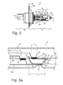
- FIG. 2 shows a side view of the lamp of FIG. 1 in the horizontal operating position
- FIG. 3 a shows an enlarged sectional view of a portion of the lamp of FIG. 1 with the section taken along line R in FIG. 1 ;
- FIG. 3 b shows an enlarged sectional view of a portion of a second embodiment of a lamp
- FIG. 4 shows in a schematic representation a vehicle headlight with a lamp according to FIGS. 1-3 .
- FIGS. 1, 2 show an automotive halogen lamp 10 .
- the lamp 10 comprises a base 12 and a burner 14 fixed to the base 12 .
- the base 12 comprises a positioning ring 16 which includes three positioning protrusions 18 a , 18 b radially protruding from the base 12 (of which only two are shown in FIG. 1 ).
- a reference plane for positioning is defined by the upper portions of the protrusions 18 a , 18 b , 18 c.
- the lamp 10 may be fixed to a vehicle headlight so as symbolically shown in FIG. 4 at the protrusions 18 a , 18 b .
- the protrusion 18 b serves as a reference protrusion defining a radial reference direction R.
- a symmetry plane is positioned to include a longitudinal axis X of the lamp 10 , extending centrally through the positioning ring 16 perpendicular to the reference plane, and the radial reference direction R extending radially from the longitudinal axis X into the direction of the reference protrusion 18 b.
- the burner 14 comprises a quartz glass vessel 22 with a central portion 24 of generally circular cylindrical shape (except for a deformation as will be described below). At the top, the otherwise transparent vessel 22 comprises a coated portion 26 which is opaque. At the bottom, the vessel 22 is sealed in a pinch seal 28 , which is fixed to the base 12 .
- the holding wires 30 a , 30 b , 30 c Projecting from the pinch seal 28 into the interior of the vessel 22 are three holding wires 30 a , 30 b , 30 c .
- the holding wires 30 a , 30 b , 30 c are further fixed by a holding bar 32 made out of quartz glass material and arranged distant from the pinch seal 28 .
- the holding wires 30 a - 30 c are embedded within the material of the holding bar 32 .
- fixed to the holding wires 30 a , 30 b , 30 c are arranged a first filament 34 (low-beam filament) and a second filament 36 (high-beam filament).
- a baffle 40 is arranged, welded to a third of the holding wires ( 30 c ). As shown, the baffle is provided to cover the axial extent of the first filament 34 and thus partially shield light emitted from the filament 34 into radial directions. Further, a front portion 42 of the baffle 40 is arranged in between the first and second filaments 34 , 36 and therefore serves to shield the filaments 34 , 36 from one another.
- the first, low beam filament 34 is connected at one end to a first holding wire 30 a and at the other end to the baffle 40 , which is welded to the third holding wire 30 c .
- the second, high-beam filament 36 is fixed to a second holding wire 30 b and to the third holding wire 30 c .
- the filaments 34 , 36 are both mechanically held at defined positions within the vessel 22 and are electrically connected between the holding wires 30 a , 30 b , 30 c .
- the holding wires are connected internally within the base 12 to electrical contacts 20 protruding from the lower portion of the base 12 .
- the filaments 34 , 36 may be operated by supplying electrical power at the electrical contacts 20 .
- FIG. 3 a shows an enlarged sectional view of the central, circular-cylindrical portion 24 of the vessel 22 .
- the filaments 34 , 36 are each provided as a single winding structure of filament wire wound around a straight filament axis.
- the filament axis 35 of the first filament 34 and the filament axis 37 of the second filament 36 are arranged in parallel to the longitudinal axis X of the lamp 10 .
- the baffle 40 comprises a bottom surface 41 from which a front surface 43 , a back surface 47 , and side surfaces 45 extend.
- the side surfaces 45 terminate in side edges 48 .
- an attachment tab 52 is integrally formed.
- the attachment tab 52 serves to connect the filament wire of the first filament 34 to the baffle 40 . It is arranged substantially flat in a plane that is oriented horizontally in FIG. 3 . As shown, the filament wire of the first filament 34 is welded to the attachment tab 52 .
- the wall of the vessel 22 is deformed at a position located in the horizontal arrangement of FIG. 2 , FIG. 3 a below the baffle 40 .
- a deformed material portion, or dimple 38 is formed in the wall of the vessel 22 to contact and partially enclose the third holding wire 30 c .
- the dimple 38 may also contact the lower surface 41 of the baffle 40 .
- the baffle 40 and the holding wire 30 c are therefore mechanically held by the wall of the vessel 22 , such that movement thereof relative to the vessel 22 is limited even under the application of forces of inertia due to vibration.
- the vessel 22 is formed without the pinch seal 28 , i.e. open to the left in FIG. 2 , FIG. 3 .
- the holding wires 30 a - 30 c with attached filaments 34 , 36 and the baffle 40 , connected together by the holding bar 32 are inserted into the interior of the vessel 22 .
- the pinch seal 28 By forming the pinch seal 28 , the holding wires 30 a - 30 c are embedded into the quartz glass material.
- the deformation 38 is formed by heating the wall of the vessel at least locally to a softening temperature and impressing the dimple 38 such that the softened quartz glass material contacts the third holding wire 30 c and at least partially encloses parts thereof, such that the holding wire 30 c and the baffle 40 adhere to the deformation 38 thus obtained.
- the deformation 38 may be formed by gas pressure, namely by applying a vacuum at the tip of the lamp 10 , such that atmospheric pressure at the exterior of the vessel 22 will form the dimple 38 at the locally heated position of the wall.
- the interior of the vessel 22 is filled with a suitable filling for a halogen lamp with a filling gas of halogen and xenon and crypton as rare gas filling before the vessel 22 is closed off at the tip.
- the gas filling is provided such that the lamp at room temperature has a cold filling pressure of 1 Mpa.
- the position of the deformation 38 is chosen to be shielded from the first filament 34 by the baffle 40 , i.e. the deformation 38 is located behind the baffle 40 as viewed from the first filament.
- the optical distortion caused by the deformation 38 is minimal, because light emitted from the first filament 34 is shaded at the baffle 40 and does not directly reach the position of the deformation 38 , whereas only a very small portion of light emitted from the second filament 36 passes through the wall of the vessel 22 at the position of the deformation 38 .
- FIG. 3 b shows an alternative embodiment in a view similar to FIG. 3 a .
- the alternative embodiment largely corresponds to the previously described first embodiment, thus only differences will be explained.
- the holding wire 30 c is provided longer such that a free end 31 projects from the point of contact to the baffle 40 .
- the dimple 38 is formed at a position closer to the tip of the lamp, and encloses the free end 31 of the holding wire 30 c.
- the alternative position of the dimple 38 as shown in FIG. 3 b further has the advantage that the dimple 38 is shielded not only from direct light emitted from the first filament 34 , but also from direct light emitted from the second filament 36 .
- optical distortion is further minimized.
- the axial length L 1 of the first filament 34 entirely overlaps with the axial length L B of the baffle 40 .
- a substantial portion of light emitted from the first filament 34 is shielded at the side edges 48 of the baffle 40 , leading to a corresponding straight bright/dark cutoff.
- FIG. 4 shows schematically a headlight 50 where the lamp 10 as described above is schematically shown arranged within a reflector 46 .
- Light emitted from the filaments 34 , 36 (not shown in FIG. 3 ) is reflected by the reflector 46 to form different illumination beams.
- Light from the second (high-beam) filament 36 is shown as a dotted line to be reflected by both the upper and lower part of the reflector 46 to form a high-beam without a bright/dark cutoff.
- first low-beam filament 34 Light emitted from the first low-beam filament 34 is shown as a dashed line to be partially shielded by the baffle 40 such that only an upper portion of the reflector 46 is illuminated.
- the upper portion of reflector 46 is shaped to reflect the light from the first filament 34 to form an illumination beam with a horizontal bright/dark cutoff. In the resulting low beam, there is no distortion from the deformation 38 , because of the position thereof behind the baffle 40 .
- the resulting beam patterns are symmetrical, too.
- the low-beam pattern will have a horizontal bright/dark cutoff.
Landscapes
- Engineering & Computer Science (AREA)
- General Engineering & Computer Science (AREA)
- Manufacturing & Machinery (AREA)
- Non-Portable Lighting Devices Or Systems Thereof (AREA)
Abstract
Description
Claims (12)
Applications Claiming Priority (4)
| Application Number | Priority Date | Filing Date | Title |
|---|---|---|---|
| EP13184366 | 2013-09-13 | ||
| EP13184366 | 2013-09-13 | ||
| EP13184366.6 | 2013-09-13 | ||
| PCT/EP2014/068720 WO2015036300A1 (en) | 2013-09-13 | 2014-09-03 | Vibration resistant automotive front lighting lamp |
Publications (2)
| Publication Number | Publication Date |
|---|---|
| US20160225605A1 US20160225605A1 (en) | 2016-08-04 |
| US9805926B2 true US9805926B2 (en) | 2017-10-31 |
Family
ID=49212604
Family Applications (1)
| Application Number | Title | Priority Date | Filing Date |
|---|---|---|---|
| US14/917,906 Expired - Fee Related US9805926B2 (en) | 2013-09-13 | 2014-09-03 | Vibration resistant automotive front lighting lamp |
Country Status (5)
| Country | Link |
|---|---|
| US (1) | US9805926B2 (en) |
| EP (1) | EP3044806B1 (en) |
| JP (1) | JP6427580B2 (en) |
| CN (1) | CN105518823B (en) |
| WO (1) | WO2015036300A1 (en) |
Families Citing this family (1)
| Publication number | Priority date | Publication date | Assignee | Title |
|---|---|---|---|---|
| WO2015052023A2 (en) * | 2013-10-09 | 2015-04-16 | Koninklijke Philips N.V. | Vibration resistant automotive front lighting lamp |
Citations (7)
| Publication number | Priority date | Publication date | Assignee | Title |
|---|---|---|---|---|
| US3469140A (en) | 1967-02-13 | 1969-09-23 | Westinghouse Electric Corp | Single-ended electric incandescent lamp with improved base and terminal structure,and method of assembly |
| US3646386A (en) * | 1968-06-08 | 1972-02-29 | Philips Corp | Halogen filament lamp for vehicle headlight with screen partially surrounding antiglare filament |
| US3774064A (en) * | 1970-04-16 | 1973-11-20 | Thorn Electrical Ind Ltd | Incandescent lamp filament supports |
| EP0817243A2 (en) | 1996-06-06 | 1998-01-07 | Honda Giken Kogyo Kabushiki Kaisha | Vehicle light bulb |
| DE102005046204A1 (en) | 2005-09-27 | 2007-03-29 | Patent-Treuhand-Gesellschaft für elektrische Glühlampen mbH | Incandescent halogen-filled lamp for medium or high voltage, comprises connected tubular sections containing lamp envelopes |
| DE102007025074A1 (en) | 2007-05-30 | 2008-12-04 | Osram Gesellschaft mit beschränkter Haftung | Incandescent lamp, particularly halogen lamp for use as headlight in motor vehicles, has lamp bulb hermetically sealed with filling of inert gas and halogen-containing additive |
| DE102008015557A1 (en) | 2008-03-06 | 2009-09-10 | Osram Gesellschaft mit beschränkter Haftung | Incandescent lamp i.e. H4 type two-filament halogen incandescent lamp, for use in headlight of motor vehicle i.e. motorcycle, has spring element resting against inner wall of lamp bulb in area of fused pumping rod |
Family Cites Families (1)
| Publication number | Priority date | Publication date | Assignee | Title |
|---|---|---|---|---|
| FR2347776A1 (en) * | 1976-04-08 | 1977-11-04 | Lampes Elect Fab Reunies | HALOGEN LAMP WITH OPTICAL FILTER |
-
2014
- 2014-09-03 US US14/917,906 patent/US9805926B2/en not_active Expired - Fee Related
- 2014-09-03 CN CN201480050246.8A patent/CN105518823B/en not_active Expired - Fee Related
- 2014-09-03 WO PCT/EP2014/068720 patent/WO2015036300A1/en not_active Ceased
- 2014-09-03 JP JP2016541885A patent/JP6427580B2/en not_active Expired - Fee Related
- 2014-09-03 EP EP14761974.6A patent/EP3044806B1/en not_active Not-in-force
Patent Citations (7)
| Publication number | Priority date | Publication date | Assignee | Title |
|---|---|---|---|---|
| US3469140A (en) | 1967-02-13 | 1969-09-23 | Westinghouse Electric Corp | Single-ended electric incandescent lamp with improved base and terminal structure,and method of assembly |
| US3646386A (en) * | 1968-06-08 | 1972-02-29 | Philips Corp | Halogen filament lamp for vehicle headlight with screen partially surrounding antiglare filament |
| US3774064A (en) * | 1970-04-16 | 1973-11-20 | Thorn Electrical Ind Ltd | Incandescent lamp filament supports |
| EP0817243A2 (en) | 1996-06-06 | 1998-01-07 | Honda Giken Kogyo Kabushiki Kaisha | Vehicle light bulb |
| DE102005046204A1 (en) | 2005-09-27 | 2007-03-29 | Patent-Treuhand-Gesellschaft für elektrische Glühlampen mbH | Incandescent halogen-filled lamp for medium or high voltage, comprises connected tubular sections containing lamp envelopes |
| DE102007025074A1 (en) | 2007-05-30 | 2008-12-04 | Osram Gesellschaft mit beschränkter Haftung | Incandescent lamp, particularly halogen lamp for use as headlight in motor vehicles, has lamp bulb hermetically sealed with filling of inert gas and halogen-containing additive |
| DE102008015557A1 (en) | 2008-03-06 | 2009-09-10 | Osram Gesellschaft mit beschränkter Haftung | Incandescent lamp i.e. H4 type two-filament halogen incandescent lamp, for use in headlight of motor vehicle i.e. motorcycle, has spring element resting against inner wall of lamp bulb in area of fused pumping rod |
Non-Patent Citations (2)
| Title |
|---|
| EPO as ISA, PCT/EP2014/08720, filed Sep. 3, 2014, "International Search Report and Written Opinion" dated Oct. 13, 2014, 10 pages. |
| Extended European Search Report dated Jan. 8, 2014 from European Patent Application No. 13184366.6. |
Also Published As
| Publication number | Publication date |
|---|---|
| WO2015036300A1 (en) | 2015-03-19 |
| CN105518823A (en) | 2016-04-20 |
| US20160225605A1 (en) | 2016-08-04 |
| EP3044806A1 (en) | 2016-07-20 |
| JP2016535421A (en) | 2016-11-10 |
| JP6427580B2 (en) | 2018-11-21 |
| EP3044806B1 (en) | 2016-11-09 |
| CN105518823B (en) | 2017-10-20 |
Similar Documents
| Publication | Publication Date | Title |
|---|---|---|
| KR20060052404A (en) | Car headlights | |
| US9805926B2 (en) | Vibration resistant automotive front lighting lamp | |
| US2880347A (en) | Sealed beam headlight with internal shield | |
| US4339685A (en) | Sealed beam lamp assembly | |
| US9899207B2 (en) | Vibration resistant automotive front lighting lamp | |
| JP6368356B2 (en) | Double filament incandescent lamp for automotive front illumination | |
| CN105164786B (en) | Automobile front lamp with dividing plate | |
| US20100039017A1 (en) | Two-filament lamp | |
| US8164240B2 (en) | Anti-dazzle device with a filament | |
| CN202352630U (en) | Closed tungsten halogen focus lamp | |
| WO2007012236A1 (en) | Xe FILLED METAL HALIDE LAMP WITH INTEGRATED DOUBLE ELECTRIC TUBES FOR VEHICLE | |
| US20050110413A1 (en) | Method for producing an electric lamp, and an electric lamp | |
| JPH06176741A (en) | Halogen lamp with infrared ray reflecting film | |
| JPH06176601A (en) | Vehicle headlights |
Legal Events
| Date | Code | Title | Description |
|---|---|---|---|
| AS | Assignment |
Owner name: KONINKLIJKE PHILIPS N.V., NETHERLANDS Free format text: ASSIGNMENT OF ASSIGNORS INTEREST;ASSIGNORS:SCHOENFELDER, BERND;DOHLEN, GERD-PETER;MOELLER, JOHANNES GERHARD;SIGNING DATES FROM 20140509 TO 20160628;REEL/FRAME:039042/0471 |
|
| STCF | Information on status: patent grant |
Free format text: PATENTED CASE |
|
| AS | Assignment |
Owner name: LUMILEDS LLC, CALIFORNIA Free format text: ASSIGNMENT OF ASSIGNORS INTEREST;ASSIGNOR:KONINKLIJKE PHILIPS N.V.;REEL/FRAME:045859/0005 Effective date: 20170428 |
|
| MAFP | Maintenance fee payment |
Free format text: PAYMENT OF MAINTENANCE FEE, 4TH YEAR, LARGE ENTITY (ORIGINAL EVENT CODE: M1551); ENTITY STATUS OF PATENT OWNER: LARGE ENTITY Year of fee payment: 4 |
|
| AS | Assignment |
Owner name: SOUND POINT AGENCY LLC, NEW YORK Free format text: SECURITY INTEREST;ASSIGNORS:LUMILEDS LLC;LUMILEDS HOLDING B.V.;REEL/FRAME:062299/0338 Effective date: 20221230 |
|
| AS | Assignment |
Owner name: LUMILEDS HOLDING B.V., NETHERLANDS Free format text: RELEASE BY SECURED PARTY;ASSIGNOR:SOUND POINT AGENCY LLC;REEL/FRAME:070046/0001 Effective date: 20240731 Owner name: LUMILEDS LLC, CALIFORNIA Free format text: RELEASE BY SECURED PARTY;ASSIGNOR:SOUND POINT AGENCY LLC;REEL/FRAME:070046/0001 Effective date: 20240731 Owner name: LUMILEDS LLC, CALIFORNIA Free format text: RELEASE OF SECURITY INTEREST;ASSIGNOR:SOUND POINT AGENCY LLC;REEL/FRAME:070046/0001 Effective date: 20240731 Owner name: LUMILEDS HOLDING B.V., NETHERLANDS Free format text: RELEASE OF SECURITY INTEREST;ASSIGNOR:SOUND POINT AGENCY LLC;REEL/FRAME:070046/0001 Effective date: 20240731 |
|
| FEPP | Fee payment procedure |
Free format text: MAINTENANCE FEE REMINDER MAILED (ORIGINAL EVENT CODE: REM.); ENTITY STATUS OF PATENT OWNER: LARGE ENTITY |
|
| LAPS | Lapse for failure to pay maintenance fees |
Free format text: PATENT EXPIRED FOR FAILURE TO PAY MAINTENANCE FEES (ORIGINAL EVENT CODE: EXP.); ENTITY STATUS OF PATENT OWNER: LARGE ENTITY |
|
| STCH | Information on status: patent discontinuation |
Free format text: PATENT EXPIRED DUE TO NONPAYMENT OF MAINTENANCE FEES UNDER 37 CFR 1.362 |
|
| FP | Lapsed due to failure to pay maintenance fee |
Effective date: 20251031 |