US980229A - Locking mechanism for emergency exit-doors. - Google Patents
Locking mechanism for emergency exit-doors. Download PDFInfo
- Publication number
- US980229A US980229A US1910572865A US980229A US 980229 A US980229 A US 980229A US 1910572865 A US1910572865 A US 1910572865A US 980229 A US980229 A US 980229A
- Authority
- US
- United States
- Prior art keywords
- door
- frame
- bolt
- plate
- traveling
- Prior art date
- Legal status (The legal status is an assumption and is not a legal conclusion. Google has not performed a legal analysis and makes no representation as to the accuracy of the status listed.)
- Expired - Lifetime
Links
Images
Classifications
-
- E—FIXED CONSTRUCTIONS
- E05—LOCKS; KEYS; WINDOW OR DOOR FITTINGS; SAFES
- E05B—LOCKS; ACCESSORIES THEREFOR; HANDCUFFS
- E05B65/00—Locks or fastenings for special use
- E05B65/10—Locks or fastenings for special use for panic or emergency doors
- E05B65/1006—Locks or fastenings for special use for panic or emergency doors of the vertical rod type
-
- Y—GENERAL TAGGING OF NEW TECHNOLOGICAL DEVELOPMENTS; GENERAL TAGGING OF CROSS-SECTIONAL TECHNOLOGIES SPANNING OVER SEVERAL SECTIONS OF THE IPC; TECHNICAL SUBJECTS COVERED BY FORMER USPC CROSS-REFERENCE ART COLLECTIONS [XRACs] AND DIGESTS
- Y10—TECHNICAL SUBJECTS COVERED BY FORMER USPC
- Y10T—TECHNICAL SUBJECTS COVERED BY FORMER US CLASSIFICATION
- Y10T292/00—Closure fasteners
- Y10T292/08—Bolts
- Y10T292/0801—Multiple
- Y10T292/0822—Emergency operating means
Definitions
- This invention relates to improvements in locking mechanism for doors and more particularly to such as is adaptable for use with emergency exit doors,one object of the invention being to provide a simple and efficient door-locking mechanism which shall be readily operable from the inside only, to quickly release the door, and which cannot be operated by picking or otherwise from the outside.
- a further object is to so construct the mechanism as to avoid frictional binding of the bolts in the keepers, and thus insure the easy withdrawal of said bolts, regardless of the amount of pressure which might be exerted against the door.
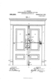
- Figure 1 isan elevation showing my improvements applied to a door.
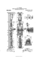
- Fig. 2 is a vertical section on the line ;cm of Fig. 1.
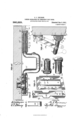
- Fig. 8 is a face view with casings in section.
- Fig. 1 is an enlarged horizontal sectional view on the line 1 y of Fig.-1.
- Fig. 5 is an enlarged sectional View on the line 2-2 of Fig. 1.
- Fig. 6 is a detail view showing the device for locking the bolt mechanism in its unlocked position.
- Fig. 7 is a detail view (partly in section) showing the lower keeper and bolt.
- Fig. 8 is a detail view of the link which connects the operating bar with the traveling frame of the lock mechanism.
- Fig. 9 is a detail view of the traveling frame.
- Lock mechanism 4 and an operating bar 5 are located on the door 2 an appreciable distance above the usual lock line of the door so that possibility of obstruction which might preventthe free action of the operating bar, will be avoided.
- I employ a frame-plate 6 secured to the door an appreciable distance above the ordinary lock line, as above indicated, and this plate is provided with a central elongated opening 7, at the vertical edges of which, flanges 8 are located and similar flanges 9 project from the side edges of the plate 6.
- the flanges 89 are parallel with each other and between their ends, these flanges are made with recesses 10 for the accommodation of a journal 11 on a rocking bar which constitutes the operating bar 5.
- Theflanges 89 thus afford half-bearings for the journal 11 of the operating bar 5 and other halfbearings 12 for said journals are secured to the frame plate 6 between the pairs of flanges 89.
- the journal 13 at the other end of the operating bar 5 enters a casing 1 1 secured near the hinged edge of the door 2. WVithin this casing, and secured to the door, is a bracket 15 having notches in its respective ends for the accommodation of sleeves 16 and 17 on the journal 13.
- the head of the sleeve 16 is provided with notches 18 for the reception of one end of the bracket 15 and the sleeve 17 is provided with a series of holes 19 to permit the adjustable attachment of said sleeve to the journal 13 by means of a pin 20, as shown in Fig. 4.
- the sleeve 17 is also provided with a head 21 having sockets 22 for the reception of a suitable tool for turning said sleeve.
- a spring 28 encircles the sleeves 16 and 17 and one end of this spring is inserted in a slot 24 in the sleeve 16 while the other end of said spring is inserted in a slot 25 in the sleeve 17. It is apparent that by removing the pin 20 and turning the sleeve 17, the ten-' sion of the spring 23 can be adjusted.
- the spring 23 serves to hold the cranked operating bar 5 elevated but the upward throw of said operating bar is limited by means of a link 26 pivoted at its lower end to said operating bar and provided at its upper end with a pin 27 projecting laterally therefrom and movable in a vertical slot 28 in a bracket 29 secured to the door 2. This connection between the operating bar and the door also serves to limit the downward movement of said bar.
- a traveling frame 30 is disposed parallel with the fixed frameplate 6 and between the flanges 8 of said plate.
- the traveling frame 30 is somewhat enlarged intermediate of its ends and enters the opening 7 of the frame plate 6,-the ends of said enlarged portion forming shoulders 31 adapted to engage the upper and lower walls of said opening in the plate 6 and thus limit the vertical move ments of said traveling frame.
- the travel ing frame 30 is also provided with recesses 32 for the accommodation of the journal 11 on the operating bar 5.
- the journal 11 is provided with an arm 33 with which the upper end of a link 34 is pivotally connected,the lower end of said link being disposed between the parallel members of the traveling frame 30 and pivotally attached thereto. 7
- a rod 35 is secured to the upper end of the traveling frame 30 and passes through a hole in the upper end of a casing 36 which incloses the lock operating mechanism,-the upper end of said rod being attached to the lower end of a plunger 37 which is vertically movable within a casing 38 secured to the door 2 near its upper end.
- a guide 39 may be secured to the door midway between the casings 36 and 3S and through this guide the rod 35 passes.
- a bracket 40 Secured to and depending from the top of the door frame and directly over the casing 38 (when the door is closed), is a bracket 40 which constitutes an abutment for the upper end of the door, as shown in Fig. 2.
- the bracket 40 has mounted therein, a latch or bolt 41,sa'id latch or bolt being pivotally supported at one end within said bracket and provided at its free end with a roller 42.
- the plunger 37 is so disposed as to permit the free end of the latch or bolt 41 to enter the upper end of the casing 38 and the roller 42 to engage the inner face of the bulged portion 43 at the upper end of said casing and thus lock the door at the top thereof.
- the traveling frame Byoperating the bar 5 the traveling frame will be caused to move upwardly and transmit motion through the rod 35 to the plunger 37 and the latter will raise the pivoted latch or bolt 4i sufficiently to free the same from the upper end of casing 38 and thus release the door so far as the upper end of the latter is concerned.
- a casing 44 is secured to the door 2 near the lower end thereof and within this casing a lower bolt is located.
- This bolt comprises a vertically movable frame 45 having a shoulder 46, and a slotted bracket 47 movable in the lower portion of the frame 45 and provided with a depending portion carrying a roller 48 to engage a floor plate or keeper 49.
- This floor plateor keeper is made with an inclined face to be engaged by the lower edge of the door and with an opening 50 to receive the lower end of the bolt member 47 and said bolt member 47 is limited in its downward movement to preventits engagement with the floor when the door is swung.
- a block 51 is located in the upper portion of the frame or bolt member 45 and provided with a lug to engage the shoulder 46 of said frame or bolt member 45 and this block is connected by means of a rod 53 r with the lower end of the traveling frame 30 of the bolt mechanism.
- a guide 54 may be provided for the rod 53 and secured to the door between the casings 36 and 44.
- a spring 55 is located between the block 51 and the lower bolt member 47., hen the operating bar 5 is manipulated to raise the traveling frame 30 and release the upper door locking devices, as above described, the lower bolt will also be raised through the medium of the rod 53 to disengage the same from the floor plate or keeper 49 and thus release the lower edge of the door.
- the yielding bolt member 47 at the lower end of the door will ride over the inclined portion of the floor plate or keeper 49 and automatically drop into the opening of the latter.
- the upper end of the casing 38 will engage the roller at the free end of the pivoted latch or bolt 41 at the top of the door casing and, after raising the same, permit it to drop and engage the bulged upper portion 43 of said casing 38, thus locking the upper edge of the door automatically.
- a latch 56 may be employed.
- This latch comprises a plate provided at one end with a thumb piece 57, and a tapering opening 58.
- the latch plate is slidably mounted upon the casing 36 and the larger portion of the opening 58 is suflicient to permit the free passage of a sleeve 59 secured to the rod hen it is desired to lock the locking mechanism in unlocked position to prevent engagement with parts 38 and 41 and 47 and 4-9, the latch plate at; is moved longitudinally and caused to engage one end of the sleeve 59,the smaller portion of the opening 58 in said latch plate permitting such operation.
- the casing which incloses the lock-opcrating mechanism on one door is covered by a faceplate 4t, and a raised plate at" is secured to the other door to simulate a casing and face-plate.
- the door 3 of the double doors shown in Fig. 1 may be provided with a rocking opcrating bar 57 and provided at one end with a portion 58 to engage the cranked operating bar 5 on the door 2 for mani nilating the locking mechanism when pressure is applied against said rocking bar 57.
- a mechanism of the character dcscribed the combination with a bracket to be secured to the top of the door frame and adapted to constitute an abutment for a door, a pivoted bolt mounted in said bracket, an abutment on the door normally engaged by said bolt, and a floor plate also adapted to constitute an abutment for a door, of a traveling member to be mounted on the door, means mounted on the door for moving said traveling member longitudinally, a plunger connected with the upper end of said traveling member for raising the pivoted bolt for releasing the latter from the abutment, and a bolt connected with the lower end of said traveling member and adapted to engage the floor plate.
- a frame plate to be secured to a door a rocking bar mounted on the frame plate and provided with an arm, a longitudinally movable traveling frame disposed parallel with the frame plate, a link connecting said traveling frame with the arm on the operating bar, bolt actuating devices, rods connecting said bolt actuating devices with the traveling frame, a sleeve or projection on one of said rods, a casing inclosing the frame plate and traveling frame, and a latch mounted on said casing and adapted to cooperate with the sleeve or projection on one of the rods for locking the mechanism against operation.
Landscapes
- Business, Economics & Management (AREA)
- Emergency Management (AREA)
- Automobile Manufacture Line, Endless Track Vehicle, Trailer (AREA)
Description
LOOKINGMBOHANIBM FOR EMERGENCY EXIT DOORS APPLICATION FILED JULY 20,1910. 980,229. Patented 3. 1911.
B SHEETS-SHEET 1.
g ifcwu/ WITNESSES A liar/12y m: uanlllrrzrins co., wunmaron. DJC.
c. J. ERI GSON.
LOCKING MEGHANISM FOR EMERGENCY EXIT DOORS.
APPLIOATION FILED JULY 80, 1910. 980,229, Patented Jan. 3, 1911.
3 SHEETS-SHEET 2.
I lllfldfllalfflfqi, ivid 0. J. ERICSON. LOOKING MECHANISM FOR EMERGENOY EXIT moons.
APPLICATION TILED JULY 20. 19101 7 980,229. v Patented Jam 3, 1911.
3 SHEETS-SHEET 3.
WITNESSES CHARLES JOS. ERICSON, 0F SALT LAKE CITY, UTAH.
LOCKING MECHANISM FOR EMERGENCY EXIT-DOORS.
Specification of Letters Patent.
Application filed July 20, 1910.
Patented Jan. 3, 1911.
Serial No. 572,865.
To all whom it may concern:
Be it known that I, CHARLES J. ERICSON, of Salt Lake City, in the county of Salt Lake and State of Utah, have invented certain new and useful Improvements in Looking Mechanism for Emergency Exit-Doors; and I do hereby declare the following to be a full, clear, and exact description of the invention, such as will enable others skilled in the art to which it appertains to make and use the same.
This invention relates to improvements in locking mechanism for doors and more particularly to such as is adaptable for use with emergency exit doors,one object of the invention being to provide a simple and efficient door-locking mechanism which shall be readily operable from the inside only, to quickly release the door, and which cannot be operated by picking or otherwise from the outside.
A further object is to so construct the mechanism as to avoid frictional binding of the bolts in the keepers, and thus insure the easy withdrawal of said bolts, regardless of the amount of pressure which might be exerted against the door.
With these objects in view the invention consists in certain novel features of construction and combinations of parts as hereinafter set forth and pointed out in the claims.
In the accompanying drawings, Figure 1 isan elevation showing my improvements applied to a door. Fig. 2 is a vertical section on the line ;cm of Fig. 1. Fig. 8 is a face view with casings in section. Fig. 1 is an enlarged horizontal sectional view on the line 1 y of Fig.-1. Fig. 5 is an enlarged sectional View on the line 2-2 of Fig. 1. Fig. 6 is a detail view showing the device for locking the bolt mechanism in its unlocked position. Fig. 7 is a detail view (partly in section) showing the lower keeper and bolt. Fig. 8 is a detail view of the link which connects the operating bar with the traveling frame of the lock mechanism. Fig. 9 is a detail view of the traveling frame. Fig. 10 is a detail view of the fixed frame plate, and Figs. 11 and 12 are detail views of sleeves which constitute portions of the mountings for the operating bar.
l-represents a door frame and 23 swinging doors mounted therein. Lock mechanism 4 and an operating bar 5 are located on the door 2 an appreciable distance above the usual lock line of the door so that possibility of obstruction which might preventthe free action of the operating bar, will be avoided.
In constructing the locking mechanism, I employ a frame-plate 6 secured to the door an appreciable distance above the ordinary lock line, as above indicated, and this plate is provided with a central elongated opening 7, at the vertical edges of which, flanges 8 are located and similar flanges 9 project from the side edges of the plate 6. The flanges 89 are parallel with each other and between their ends, these flanges are made with recesses 10 for the accommodation of a journal 11 on a rocking bar which constitutes the operating bar 5. Theflanges 89 thus afford half-bearings for the journal 11 of the operating bar 5 and other halfbearings 12 for said journals are secured to the frame plate 6 between the pairs of flanges 89. The journal 13 at the other end of the operating bar 5 enters a casing 1 1 secured near the hinged edge of the door 2. WVithin this casing, and secured to the door, is a bracket 15 having notches in its respective ends for the accommodation of sleeves 16 and 17 on the journal 13. The head of the sleeve 16 is provided with notches 18 for the reception of one end of the bracket 15 and the sleeve 17 is provided with a series of holes 19 to permit the adjustable attachment of said sleeve to the journal 13 by means of a pin 20, as shown in Fig. 4. The sleeve 17 is also provided with a head 21 having sockets 22 for the reception of a suitable tool for turning said sleeve. A spring 28 encircles the sleeves 16 and 17 and one end of this spring is inserted in a slot 24 in the sleeve 16 while the other end of said spring is inserted in a slot 25 in the sleeve 17. It is apparent that by removing the pin 20 and turning the sleeve 17, the ten-' sion of the spring 23 can be adjusted. The spring 23 serves to hold the cranked operating bar 5 elevated but the upward throw of said operating bar is limited by means of a link 26 pivoted at its lower end to said operating bar and provided at its upper end with a pin 27 projecting laterally therefrom and movable in a vertical slot 28 in a bracket 29 secured to the door 2. This connection between the operating bar and the door also serves to limit the downward movement of said bar.
A traveling frame 30 is disposed parallel with the fixed frameplate 6 and between the flanges 8 of said plate. The traveling frame 30 is somewhat enlarged intermediate of its ends and enters the opening 7 of the frame plate 6,-the ends of said enlarged portion forming shoulders 31 adapted to engage the upper and lower walls of said opening in the plate 6 and thus limit the vertical move ments of said traveling frame. The travel ing frame 30 is also provided with recesses 32 for the accommodation of the journal 11 on the operating bar 5. The journal 11 is provided with an arm 33 with which the upper end of a link 34 is pivotally connected,the lower end of said link being disposed between the parallel members of the traveling frame 30 and pivotally attached thereto. 7
From the construction and arrangement of parts above described it will be seen that when the operating bar 5 is rocked in one direction by pressure thereagainst, vertical movement will be imparted to the traveling frame 30 and this movement willbe imparted to the bolt devices, as will now be eX- plained.
The lower end of a rod 35 is secured to the upper end of the traveling frame 30 and passes through a hole in the upper end of a casing 36 which incloses the lock operating mechanism,-the upper end of said rod being attached to the lower end of a plunger 37 which is vertically movable within a casing 38 secured to the door 2 near its upper end. A guide 39 may be secured to the door midway between the casings 36 and 3S and through this guide the rod 35 passes. Secured to and depending from the top of the door frame and directly over the casing 38 (when the door is closed), is a bracket 40 which constitutes an abutment for the upper end of the door, as shown in Fig. 2. The bracket 40 has mounted therein, a latch or bolt 41,sa'id latch or bolt being pivotally supported at one end within said bracket and provided at its free end with a roller 42. Normally, the plunger 37 is so disposed as to permit the free end of the latch or bolt 41 to enter the upper end of the casing 38 and the roller 42 to engage the inner face of the bulged portion 43 at the upper end of said casing and thus lock the door at the top thereof. By mounting the latch orbolt 41 in a bracket which depends below. the upper edge of the door and forms anabutment for the latter, it will be impossible to manipulate said latch or bolt from the outside by means of a wire or other picking instrument. Byoperating the bar 5 the traveling frame will be caused to move upwardly and transmit motion through the rod 35 to the plunger 37 and the latter will raise the pivoted latch or bolt 4i sufficiently to free the same from the upper end of casing 38 and thus release the door so far as the upper end of the latter is concerned. p
A casing 44 is secured to the door 2 near the lower end thereof and within this casing a lower bolt is located. This bolt comprises a vertically movable frame 45 having a shoulder 46, and a slotted bracket 47 movable in the lower portion of the frame 45 and provided with a depending portion carrying a roller 48 to engage a floor plate or keeper 49. This floor plateor keeper is made with an inclined face to be engaged by the lower edge of the door and with an opening 50 to receive the lower end of the bolt member 47 and said bolt member 47 is limited in its downward movement to preventits engagement with the floor when the door is swung. A block 51 is located in the upper portion of the frame or bolt member 45 and provided with a lug to engage the shoulder 46 of said frame or bolt member 45 and this block is connected by means of a rod 53 r with the lower end of the traveling frame 30 of the bolt mechanism. A guide 54 may be provided for the rod 53 and secured to the door between the casings 36 and 44. A spring 55 is located between the block 51 and the lower bolt member 47., hen the operating bar 5 is manipulated to raise the traveling frame 30 and release the upper door locking devices, as above described, the lower bolt will also be raised through the medium of the rod 53 to disengage the same from the floor plate or keeper 49 and thus release the lower edge of the door. hen the door is being closed, the yielding bolt member 47 at the lower end of the door will ride over the inclined portion of the floor plate or keeper 49 and automatically drop into the opening of the latter. At the same time the upper end of the casing 38 will engage the roller at the free end of the pivoted latch or bolt 41 at the top of the door casing and, after raising the same, permit it to drop and engage the bulged upper portion 43 of said casing 38, thus locking the upper edge of the door automatically. I
From the above description of the con- 'struction and arrangement of the locking mechanism, it will be apparent that any pressure which is brought to bear againstthe cranked operating bar 5 will cause the traveling frame 30 to move longitudinally and promptly actuate the locking devices at both ends of the door to immediately release the latter and, as the locking devices at both ends of the door are provided with means to reduce friction to a minimum, liability of binding will be avoided regardless of the amountof pressure which might be applied to the door. I
Should it be desired to lock the locking mechanism in unlocked position, a latch 56 may be employed. This latch comprises a plate provided at one end with a thumb piece 57, and a tapering opening 58. The latch plate is slidably mounted upon the casing 36 and the larger portion of the opening 58 is suflicient to permit the free passage of a sleeve 59 secured to the rod hen it is desired to lock the locking mechanism in unlocked position to prevent engagement with parts 38 and 41 and 47 and 4-9, the latch plate at; is moved longitudinally and caused to engage one end of the sleeve 59,the smaller portion of the opening 58 in said latch plate permitting such operation.
The casing which incloses the lock-opcrating mechanism on one door is covered by a faceplate 4t, and a raised plate at" is secured to the other door to simulate a casing and face-plate.
The door 3 of the double doors shown in Fig. 1 may be provided with a rocking opcrating bar 57 and provided at one end with a portion 58 to engage the cranked operating bar 5 on the door 2 for mani nilating the locking mechanism when pressure is applied against said rocking bar 57.
Slight changes might be made in the details of my invention without departing from the spirit thereof or limiting its scope and hence I do not wish to restrict myself to the precise details herein set forth.
Having fully described my invention what I claim as new and desire to secure by Letters-Patent is,-
1. In locking mechanism of the character described, the combination with a traveling frame and means for moving the same longitudinally, of longitudinally movable members rigidly connected with the respective ends of said traveling frame, and bolts to be actuated simultaneously by said longitudinally movable members to release a door to which the mechanism may be applied.
2. I11 a mechanism of the character dcscribed, the combination with a bracket to be secured to the top of the door frame and adapted to constitute an abutment for a door, a pivoted bolt mounted in said bracket, an abutment on the door normally engaged by said bolt, and a floor plate also adapted to constitute an abutment for a door, of a traveling member to be mounted on the door, means mounted on the door for moving said traveling member longitudinally, a plunger connected with the upper end of said traveling member for raising the pivoted bolt for releasing the latter from the abutment, and a bolt connected with the lower end of said traveling member and adapted to engage the floor plate.
. 3. The combination with a bracket to be secured to the top of a door frame, a pivoted bolt mounted in said bracket, an abutment on the door normally engaged by said bolt, and a floor plate or keeper, of a plunger for raising said pivoted bolt to release it from said abutment, a casing for said plunger to be secured to a door and having said abutment at its upper end, a longitudinally movable member to be secured to the lower portion'of the door, a yielding bolt member carried by said longitudinally movable member and adapted to engage the floor plate or keeper, a traveling member to be mounted on the door and operatively connected with said plunger and longitudinally movable member, and means for moving said traveling member to simultaneously operate the plungeand longitudinally movable member.
a. In locking mechanism of the character described, the combination with a fixed frame plate, and a rocking operating bar having mountings in said frame plate, of a longitudinally movable traveling f 'ame mounted on the fran'le plate, means connecting said traveling frame with the operating bar, and bolt operating devices fixed to and operable by said traveling fran'ie.
5. In locking mechanism of the character described, the combination with a fixed frame plate, a rocking operating bar having mountings therein, and bolts, of a longitudinally movable member mounted on the frame plate, means rigidly secured to said movable frame for actuating the bolts to release the same from their keepers, and a link connecting the movable frame with the rocking operating bar.
6. In locking mechanism of the character described, the combination with a fixed frame plate and a rocking bar having mountings therein and provided with an arm, of a longitudinally movable traveling frame mounted on the frame plate, a link connecting the arm on the ope 'ating bar with said traveling frame, and bolt operating devices rigidly connected with and 0p erable by said traveling frame.
7. In locking mechanism of the cha 'acter described, the combination with bolt devices and a fixed frame plate, of a traveling frame provided with shoulders or stops to engage the fixed frame plate, an operating bar having mountings in the fixed frame plate, connections between said operating bar and the traveling frame, and connections between said traveling frame and the bolt devices.
8. In locking mechanism of the character described, the combination with a fixed frame plate provided with bearings and a bracket spaced therefrom, of a cranked operating bar having a journal at one end projecting into said bracket and having a journal at the other end mounted in the hearings on the frame plate, sleeves on the first mentioned journal and connected with said journal and bracket respectively, a spring encircling said sleeves and secured at its ends to the respective sleeves, a travel ing frame disposed parallel with the frame plate, connections between said traveling frame and the operating bar, and both devices operable by said traveling frame.
9. In locking mechanism of the character described, the combination with a frame plate and a bracket spaced therefrom, of a cranked operating bar having mountings in said. frame plate and bracket, a spring tending to move said bar in one direct-ion, a slotted bracket secured to the door, a link connecting said slotted bracket with the operating bar for limiting the movement of the latter, and bolt devices, of a traveling frame disposed parallel with the frame plate, connections between said traveling frame and the operating bar, and means connected with said traveling frame for operating the bolt devices for releasing the same from their keepers.
10. The combination with a frame plate provided with parallel flanges having notches, a rocking operating bar having a journal mounted in said notches, half-bearings secured to the frame plate between the flanges thereof and retaining the journal of the operating bar in place, and bolt devices, of a traveling frame disposed between the pairs of flanges on the frame plate, connections between said operating bar and traveling frame for moving the latter longitudinally, and connections between said traveling frame and the bolt devices.
11. The combination of a frame plate to be secured to a door, a rocking bar mounted on the frame plate and provided with an arm, a longitudinally movable traveling frame disposed parallel with the frame plate, a link connecting said traveling frame with the arm on the operating bar, bolt actuating devices, rods connecting said bolt actuating devices with the traveling frame, a sleeve or projection on one of said rods, a casing inclosing the frame plate and traveling frame, and a latch mounted on said casing and adapted to cooperate with the sleeve or projection on one of the rods for locking the mechanism against operation.
In testimony whereof, I have signed this specification in the presence of two subscribing witnesses.
CHARLES J OS. ERICSON.
lVitnesses:
ALONZO YOUNG, A. J ORGENSON.
Priority Applications (1)
| Application Number | Priority Date | Filing Date | Title |
|---|---|---|---|
| US1910572865 US980229A (en) | 1910-07-20 | 1910-07-20 | Locking mechanism for emergency exit-doors. |
Applications Claiming Priority (1)
| Application Number | Priority Date | Filing Date | Title |
|---|---|---|---|
| US1910572865 US980229A (en) | 1910-07-20 | 1910-07-20 | Locking mechanism for emergency exit-doors. |
Publications (1)
| Publication Number | Publication Date |
|---|---|
| US980229A true US980229A (en) | 1911-01-03 |
Family
ID=3048603
Family Applications (1)
| Application Number | Title | Priority Date | Filing Date |
|---|---|---|---|
| US1910572865 Expired - Lifetime US980229A (en) | 1910-07-20 | 1910-07-20 | Locking mechanism for emergency exit-doors. |
Country Status (1)
| Country | Link |
|---|---|
| US (1) | US980229A (en) |
Cited By (1)
| Publication number | Priority date | Publication date | Assignee | Title |
|---|---|---|---|---|
| US3345099A (en) * | 1965-09-14 | 1967-10-03 | Sargent & Greenleaf | Panic exit device |
-
1910
- 1910-07-20 US US1910572865 patent/US980229A/en not_active Expired - Lifetime
Cited By (1)
| Publication number | Priority date | Publication date | Assignee | Title |
|---|---|---|---|---|
| US3345099A (en) * | 1965-09-14 | 1967-10-03 | Sargent & Greenleaf | Panic exit device |
Similar Documents
| Publication | Publication Date | Title |
|---|---|---|
| US980229A (en) | Locking mechanism for emergency exit-doors. | |
| US1014960A (en) | Locking mechanism for doors. | |
| US1117457A (en) | Door-lock. | |
| US423739A (en) | Car-door | |
| US920501A (en) | Lock. | |
| US1060317A (en) | Means for automatically unlocking doors. | |
| US1067241A (en) | Safety door-bolt. | |
| US562075A (en) | Transom-sash adjuster | |
| US1102578A (en) | Farm-gate. | |
| US416312A (en) | Latch | |
| US1084733A (en) | Farm-gate. | |
| US666489A (en) | Lock. | |
| US964525A (en) | Device for operating and locking prison-doors. | |
| US824545A (en) | Automatic sash-lock. | |
| US549989A (en) | Door for elevators or other inclosures | |
| US1405977A (en) | Door latch | |
| US533205A (en) | bergman | |
| US809184A (en) | Multiple-bolt mechanism. | |
| US1052721A (en) | Window structure. | |
| US1681374A (en) | Gate | |
| US1133953A (en) | Car-door lock. | |
| US299451A (en) | Josiah austin and e | |
| US508879A (en) | Mine trap-door | |
| US595377A (en) | L duncan | |
| US573439A (en) | Sash fastener and support |