US9762166B2 - Method for field-oriented control of a frequency converter for a three-phase motor - Google Patents
Method for field-oriented control of a frequency converter for a three-phase motor Download PDFInfo
- Publication number
- US9762166B2 US9762166B2 US15/248,201 US201615248201A US9762166B2 US 9762166 B2 US9762166 B2 US 9762166B2 US 201615248201 A US201615248201 A US 201615248201A US 9762166 B2 US9762166 B2 US 9762166B2
- Authority
- US
- United States
- Prior art keywords
- rotation
- edge
- angle
- respect
- coordinate system
- Prior art date
- Legal status (The legal status is an assumption and is not a legal conclusion. Google has not performed a legal analysis and makes no representation as to the accuracy of the status listed.)
- Expired - Fee Related
Links
Images

Classifications
-
- H—ELECTRICITY
- H02—GENERATION; CONVERSION OR DISTRIBUTION OF ELECTRIC POWER
- H02P—CONTROL OR REGULATION OF ELECTRIC MOTORS, ELECTRIC GENERATORS OR DYNAMO-ELECTRIC CONVERTERS; CONTROLLING TRANSFORMERS, REACTORS OR CHOKE COILS
- H02P21/00—Arrangements or methods for the control of electric machines by vector control, e.g. by control of field orientation
- H02P21/24—Vector control not involving the use of rotor position or rotor speed sensors
- H02P21/28—Stator flux based control
Definitions
- the drive signals here are pulse-width modulated (PWM), so that the desired position of the rotary field can be adjusted by the pulse duration of the signals.
- PWM pulse-width modulated
- This method is also to be used for motors with high rotary speeds and at high drive frequencies.
- the switching frequency is critical here in respect of the desired sinusoidal form of the motor drive signals.
- offset clocking is chosen as the drive scheme.
- the microcontroller here modulates both edges of the PWM signals.
- the motor thus receives an appropriate voltage pulse at each edge. Inside the controller this is preferably done by a timer that counts upwards from zero to a maximum for the first edge, and counts downwards to zero for the second edge.
- the contents of three compare registers for the three phases are compared with the counter status.
- the raw signals for the end-stage transistors are generated from the counter direction and the compare-match signals.
- the compare values are preferably calculated afresh for each edge. For example, at 100,000 rpm, with two pole pairs and a switching frequency of 25 kHz, the field of the motor turns by 24° between one switching edge and the next switching edge. Thus at a switching frequency of 25 kHz, a time of only 20 ⁇ s is available. This means that it is necessary to use a microcontroller with a very high computing power.
- the object is achieved by a method for field-oriented control of a frequency converter for a three-phase motor, in which the setting a new position of the rotary field in the three-phase motor is performed by use of voltage pulses for the stator coils, wherein the amplitude and the angle of the rotary field vector are specified by the duration of the voltage pulses for the respective coils and by their temporal offset.
- the duration and the offset of voltage pulses for the stator coils are the result of the calculation of manipulated variables in a digitally controlled process in a coordinate system fixed in respect of the rotor, depending on the prevailing angular rotation and the prevailing speed of rotation as well as on the prevailing current values, a predetermined torque and a predetermined speed of rotation, where the manipulated variables calculated in the coordinate system that is fixed in respect of the rotor are converted through a reverse transformation into manipulated variables in a coordinate system fixed in respect of the stator, and the times for the edges of the voltage pulses are determined from these manipulated variables in the coordinate system fixed in respect of the stator.
- the calculation of the manipulated variables in the coordinate system fixed in respect of the stator for the second edge of a voltage pulse is divided into two partial calculations for the angle of rotation for the first edge and the angle of rotation from the first to the second edge, wherein the first partial calculation for the first edge has already been calculated, and the second partial calculation is used for a predetermined number of coordinate rotations.
- a complete reverse transformation is thus also no longer calculated.
- the coordinate rotation for the second edge is instead divided into two partial rotations.
- the first rotation of the coordinates has already been calculated for the first edge, the second partial rotation always occurs at the same angle for the same speed of rotation, so that the transformation matrix, in which computationally intensive sine and cosine calculations are necessary, only has to be recalculated comparatively rarely.
- the second rotation of the coordinate system thus only represents a multiplication of a vector with a matrix, which many microcontrollers can deal with extremely quickly.
- a cosine of the partial angle of rotation is approximated by 1 and a sine of the partial angle of rotation is approximated by the angle itself in the reverse transformation matrix of the second partial calculation.
- the second rotation matrix can thus be calculated by an approximation with high dynamic performance. Since the angle is small, the cosine of the additional angle can be approximated by 1, while the sine of the angle can be approximated by the angle itself.
- the value of the time for the first edge of a voltage pulse is used for calculating the time for the second edge of this voltage pulse, and the reverse transformation into the coordinate system fixed in respect of the stator is performed by an angle of rotation that is extrapolated from the angle of rotation for the first edge of the voltage pulse and the speed of rotation.
- the calculation of the current controllers is omitted.
- the field angle is extrapolated from the speed of rotation and the field angle most recently calculated from the stator coil currents, although the previously calculated voltage values are used again.
- the calculation for the second edge thus now only consists of the reverse transformation into the coordinate system fixed in respect of the stator by the extrapolated field angle.
- a particularly exotic combination is possible in which the coordinate rotation of the first edge is used together with a further rotation for the second edge, but in which the current controllers are nevertheless recalculated.
- Parts of the field-oriented control are thus replaced in a manner according to the invention by extrapolations that can be calculated much faster.
- the particularly complex coordinate rotation is replaced by an apparently more complex double rotation which can, however, be calculated significantly faster, since the first complex partial rotation has already been fully calculated, and the computationally intensive part for the second rotation is rarely calculated, or the calculation is approximated.
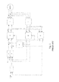
- FIG. 1 is a schematic illustration of a frequency converter with field-oriented control for a three-phase motor with a permanent magnet motor according to the prior art
- FIG. 2 is an illustration showing the conversion from coordinates that are fixed in respect of the a rotor into coordinates that are fixed with respect to the stator using a calculation of two partial rotations according to the invention.
- FIG. 1 a synchronous three-phase motor with a permanent magnet rotor PMSM is driven in the known manner using three pulse-modulated voltages UR, US, UT.
- the pulse-modulated voltages UR, US, UT are generated by a modulation unit 6 which, for example, carries out a vector modulation.
- the currents IR, IS, IT which flow through the stator coils of the three-phase motor as a result of the pulse-modulated voltages UR, US, UT are detected, for example by use of shunt resistors, and are supplied to a transformation unit 7 which calculates from these the current pointers lalpha, Ibeta representing the field position in the motor in a complex coordinate system fixed in respect of the stator.
- the current pointers Ialpha, Ibeta of the coordinate system fixed in respect of the stator are converted in a conversion unit 8 into the current pointers ID, IQ in a coordinate system fixed in respect of the rotor. This requires the angle of the rotor position theta, which is determined in a rotor position estimator 9 from the pointers lalpha, Ibeta of the coordinate system fixed in respect of the stator and the manipulated variables Ualpha, Ubeta in the coordinate system fixed in respect of the stator.
- the current pointers ID and IQ of the coordinate system fixed in respect of the rotor are supplied to a current controller ID 2 or to a current controller IQ 3 , wherein the current controller ID 2 controls the field-forming or field-weakening current ID and, in the example illustrated, is supplied with a setpoint variable of 0, since neither field reinforcement nor field attenuation are wanted.
- the current controller IQ 3 is supplied with a setpoint variable for the torque-developing current IQ. This setpoint variable is made available by a speed controller 1 , to which on the one hand a setpoint rotation speed omega_set and on the other hand a prevailing rotation speed omega determined by the rotor position estimator 9 are supplied.
- the output signals of the current controller ID 2 and of the current controller IQ 3 are each added to an output signal of a decoupling or pre-control unit 4 , to which both the current pointers ID, IQ of the coordinate system fixed in respect of the rotor, as well as the prevailing speed of rotation omega are supplied.
- the voltage pointers UD, UQ of the coordinate system fixed in respect of the rotor obtained by the additions are passed to a reverse transformation unit 5 which, using the rotor position angle theta from the rotor position estimator 9 , transforms the voltage pointers UD, UQ of the coordinate system fixed in respect of the rotor into the voltage pointers Ualpha, Ubeta of the coordinate system fixed in respect of the stator.
- These voltage pointers Ualpha, Ubeta of the coordinate system fixed in respect of the stator are passed to the modulation unit 6 .
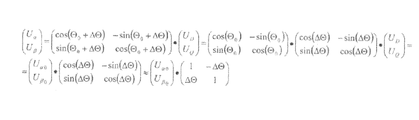
- the transformation matrix for calculating the voltage pointers U ⁇ , U ⁇ of the coordinate system fixed in respect of the stator from the voltage pointers U D , U Q of the coordinate system fixed in respect of the rotor is illustrated in FIG. 2 in the upper line in the formula on the left.b
- the calculation of the sine and cosine values for the new rotor position angles ⁇ 0 + ⁇ of the matrix elements is very computationally intensive, and requires a microcontroller that is capable of higher performance than would be commercially appropriate for the majority of applications.
- the transformation is divided through a trigonometrical transformation and matrix decomposition into two partial transformations.
- the first partial transformation calculates the voltage pointers U ⁇ , U ⁇ fixed in respect of the stator at the time of the first edge of the drive pulse for the three-phase motor from the voltage pointers U D , U Q fixed in respect of the rotor, and can consequently be used for both edges, which saves computing time.
- the second partial transformation into the right-hand part of the first line of FIG. 2 calculates the partial rotation through a small angle, and is, in the manner according to the invention, only carried out approximately, in that the sine and cosine functions are replaced by a number of terms of a Taylor series for the sine and cosine functions sufficient for the accuracy requirements.
- the calculation is used for a number of partial rotations sufficient for the accuracy requirements, and consequently only recalculated for example every three or four partial rotations. This too saves a great deal of computing time, but nevertheless yields sufficient accuracy without entirely foregoing calculation of the second edge.
Landscapes
- Engineering & Computer Science (AREA)
- Power Engineering (AREA)
- Control Of Ac Motors In General (AREA)
Abstract
Description
Claims (3)
Applications Claiming Priority (3)
| Application Number | Priority Date | Filing Date | Title |
|---|---|---|---|
| DE102015216309.1A DE102015216309B4 (en) | 2015-08-26 | 2015-08-26 | Method for field-oriented control of a frequency converter for a three-phase motor |
| DE102015216309.1 | 2015-08-26 | ||
| DE102015216309 | 2015-08-26 |
Publications (2)
| Publication Number | Publication Date |
|---|---|
| US20170063266A1 US20170063266A1 (en) | 2017-03-02 |
| US9762166B2 true US9762166B2 (en) | 2017-09-12 |
Family
ID=58011142
Family Applications (1)
| Application Number | Title | Priority Date | Filing Date |
|---|---|---|---|
| US15/248,201 Expired - Fee Related US9762166B2 (en) | 2015-08-26 | 2016-08-26 | Method for field-oriented control of a frequency converter for a three-phase motor |
Country Status (3)
| Country | Link |
|---|---|
| US (1) | US9762166B2 (en) |
| CN (1) | CN106487305B (en) |
| DE (1) | DE102015216309B4 (en) |
Families Citing this family (3)
| Publication number | Priority date | Publication date | Assignee | Title |
|---|---|---|---|---|
| DE102016213656B4 (en) | 2016-07-26 | 2023-12-07 | Vitesco Technologies GmbH | Device for regulating the speed of an electric drive |
| DE102017215281A1 (en) | 2017-08-31 | 2019-02-28 | Continental Automotive Gmbh | Method for determining the current values in a three-phase system |
| CN113569370B (en) * | 2020-04-28 | 2023-09-22 | 上海电力大学 | Calculation method of permanent magnet motor rotor eccentric magnetic field based on hyperbolic cotangent transformation method |
Citations (8)
| Publication number | Priority date | Publication date | Assignee | Title |
|---|---|---|---|---|
| US4814677A (en) * | 1987-12-14 | 1989-03-21 | General Electric Company | Field orientation control of a permanent magnet motor |
| DE102006052042A1 (en) | 2006-10-30 | 2008-05-15 | Bombardier Transportation Gmbh | Control and / or regulation of a 3-phase power converter for the operation of an asynchronous machine |
| US8552672B2 (en) * | 2010-10-19 | 2013-10-08 | Teknic, Inc. | Method and apparatus to drive two-phase motors from a three-phase bridge |
| US8853979B2 (en) * | 2011-02-28 | 2014-10-07 | Deere & Company | Method and system for calibrating rotor position offset of an electric motor |
| US8872455B2 (en) * | 2012-05-22 | 2014-10-28 | Deere & Company | Method and controller for an electric motor with fault detection |
| US8884566B2 (en) * | 2011-07-28 | 2014-11-11 | Vestas Wind Systems A/S | Method of position sensorless control of an electrical machine |
| US20140333241A1 (en) | 2013-05-12 | 2014-11-13 | Infineon Technologies Ag | Optimized control for synchronous motors |
| DE102014106668A1 (en) | 2013-05-12 | 2015-04-02 | Infineon Technologies Ag | OPTIMIZED CONTROL FOR SYNCHRONOUS MOTORS |
Family Cites Families (1)
| Publication number | Priority date | Publication date | Assignee | Title |
|---|---|---|---|---|
| JP2011041374A (en) * | 2009-08-07 | 2011-02-24 | Ricoh Co Ltd | Motor control device |
-
2015
- 2015-08-26 DE DE102015216309.1A patent/DE102015216309B4/en active Active
-
2016
- 2016-08-26 CN CN201610730171.9A patent/CN106487305B/en active Active
- 2016-08-26 US US15/248,201 patent/US9762166B2/en not_active Expired - Fee Related
Patent Citations (9)
| Publication number | Priority date | Publication date | Assignee | Title |
|---|---|---|---|---|
| US4814677A (en) * | 1987-12-14 | 1989-03-21 | General Electric Company | Field orientation control of a permanent magnet motor |
| DE102006052042A1 (en) | 2006-10-30 | 2008-05-15 | Bombardier Transportation Gmbh | Control and / or regulation of a 3-phase power converter for the operation of an asynchronous machine |
| US8129936B2 (en) | 2006-10-30 | 2012-03-06 | Bombardier Transportation Gmbh | Open-loop and/or closed-loop control system of a 3-phase power converter for the operation of an asynchronous machine |
| US8552672B2 (en) * | 2010-10-19 | 2013-10-08 | Teknic, Inc. | Method and apparatus to drive two-phase motors from a three-phase bridge |
| US8853979B2 (en) * | 2011-02-28 | 2014-10-07 | Deere & Company | Method and system for calibrating rotor position offset of an electric motor |
| US8884566B2 (en) * | 2011-07-28 | 2014-11-11 | Vestas Wind Systems A/S | Method of position sensorless control of an electrical machine |
| US8872455B2 (en) * | 2012-05-22 | 2014-10-28 | Deere & Company | Method and controller for an electric motor with fault detection |
| US20140333241A1 (en) | 2013-05-12 | 2014-11-13 | Infineon Technologies Ag | Optimized control for synchronous motors |
| DE102014106668A1 (en) | 2013-05-12 | 2015-04-02 | Infineon Technologies Ag | OPTIMIZED CONTROL FOR SYNCHRONOUS MOTORS |
Also Published As
| Publication number | Publication date |
|---|---|
| DE102015216309B4 (en) | 2023-12-28 |
| CN106487305A (en) | 2017-03-08 |
| CN106487305B (en) | 2019-01-22 |
| US20170063266A1 (en) | 2017-03-02 |
| DE102015216309A1 (en) | 2017-03-02 |
Similar Documents
| Publication | Publication Date | Title |
|---|---|---|
| CN102025312B (en) | Motor control device and electrical equipment | |
| US9590552B2 (en) | Motor drive device and electric compressor | |
| US9214884B2 (en) | Motor driving device and brushless motor | |
| US10008970B2 (en) | Control apparatus for AC motor | |
| EP2779414A2 (en) | Motor control system having bandwidth compensation | |
| JP6661837B2 (en) | Motor vector control method, apparatus and aircraft | |
| EP2779431A2 (en) | Generation of a current reference to control a brushless motor | |
| EP3070836B1 (en) | Methods of auto tuning machine parameters and systems thereof | |
| CN109496393B (en) | Electric power steering apparatus | |
| US20180248501A1 (en) | Motor drive apparatus and motor drive apparatus control method | |
| US9762166B2 (en) | Method for field-oriented control of a frequency converter for a three-phase motor | |
| JP5170505B2 (en) | Motor control device | |
| JP6514683B2 (en) | Motor device | |
| KR20140017764A (en) | Method and apparatus for obtaining maximum possible magnetic flux in permanant magnet synchronous motor | |
| JP2014128052A5 (en) | ||
| KR101618722B1 (en) | Motor drive system | |
| US9553539B2 (en) | Methods of generating output variable voltage for electric drive devices and systems thereof | |
| CN107852114A (en) | Motor control method and controller for motor | |
| CN104038114A (en) | Sine-wave voltage driving system of single-winding brushless direct current motor and control method thereof | |
| JP7287259B2 (en) | electric motor controller | |
| JP2010063336A (en) | Controller for rotary machine | |
| CN113424427A (en) | Power conversion device and electric power steering device | |
| JP7042568B2 (en) | Motor control device and motor control method | |
| CN104836505A (en) | Motor driving device and method and motor | |
| CN117318580A (en) | A switched reluctance motor current and torque collaborative control method and system |
Legal Events
| Date | Code | Title | Description |
|---|---|---|---|
| AS | Assignment |
Owner name: CONTINENTAL AUTOMOTIVE GMBH, GERMANY Free format text: ASSIGNMENT OF ASSIGNORS INTEREST;ASSIGNOR:GOETZENBERGER, MARTIN;REEL/FRAME:039995/0239 Effective date: 20160829 |
|
| STCF | Information on status: patent grant |
Free format text: PATENTED CASE |
|
| AS | Assignment |
Owner name: VITESCO TECHNOLOGIES GMBH, GERMANY Free format text: ASSIGNMENT OF ASSIGNORS INTEREST;ASSIGNOR:CONTINENTAL AUTOMOTIVE GMBH;REEL/FRAME:053323/0914 Effective date: 20200601 |
|
| MAFP | Maintenance fee payment |
Free format text: PAYMENT OF MAINTENANCE FEE, 4TH YEAR, LARGE ENTITY (ORIGINAL EVENT CODE: M1551); ENTITY STATUS OF PATENT OWNER: LARGE ENTITY Year of fee payment: 4 |
|
| FEPP | Fee payment procedure |
Free format text: MAINTENANCE FEE REMINDER MAILED (ORIGINAL EVENT CODE: REM.); ENTITY STATUS OF PATENT OWNER: LARGE ENTITY |
|
| LAPS | Lapse for failure to pay maintenance fees |
Free format text: PATENT EXPIRED FOR FAILURE TO PAY MAINTENANCE FEES (ORIGINAL EVENT CODE: EXP.); ENTITY STATUS OF PATENT OWNER: LARGE ENTITY |
|
| STCH | Information on status: patent discontinuation |
Free format text: PATENT EXPIRED DUE TO NONPAYMENT OF MAINTENANCE FEES UNDER 37 CFR 1.362 |
|
| FP | Lapsed due to failure to pay maintenance fee |
Effective date: 20250912 |