US9740193B2 - Sensor-based safety features for robotic equipment - Google Patents
Sensor-based safety features for robotic equipment Download PDFInfo
- Publication number
- US9740193B2 US9740193B2 US14/432,732 US201414432732A US9740193B2 US 9740193 B2 US9740193 B2 US 9740193B2 US 201414432732 A US201414432732 A US 201414432732A US 9740193 B2 US9740193 B2 US 9740193B2
- Authority
- US
- United States
- Prior art keywords
- robotic equipment
- boundary
- robotic
- model image
- equipment
- Prior art date
- Legal status (The legal status is an assumption and is not a legal conclusion. Google has not performed a legal analysis and makes no representation as to the accuracy of the status listed.)
- Active, expires
Links
Images


Classifications
-
- G—PHYSICS
- G05—CONTROLLING; REGULATING
- G05B—CONTROL OR REGULATING SYSTEMS IN GENERAL; FUNCTIONAL ELEMENTS OF SUCH SYSTEMS; MONITORING OR TESTING ARRANGEMENTS FOR SUCH SYSTEMS OR ELEMENTS
- G05B19/00—Programme-control systems
- G05B19/02—Programme-control systems electric
- G05B19/18—Numerical control [NC], i.e. automatically operating machines, in particular machine tools, e.g. in a manufacturing environment, so as to execute positioning, movement or co-ordinated operations by means of programme data in numerical form
- G05B19/406—Numerical control [NC], i.e. automatically operating machines, in particular machine tools, e.g. in a manufacturing environment, so as to execute positioning, movement or co-ordinated operations by means of programme data in numerical form characterised by monitoring or safety
- G05B19/4061—Avoiding collision or forbidden zones
-
- B—PERFORMING OPERATIONS; TRANSPORTING
- B25—HAND TOOLS; PORTABLE POWER-DRIVEN TOOLS; MANIPULATORS
- B25J—MANIPULATORS; CHAMBERS PROVIDED WITH MANIPULATION DEVICES
- B25J9/00—Programme-controlled manipulators
- B25J9/16—Programme controls
- B25J9/1674—Programme controls characterised by safety, monitoring, diagnostic
- B25J9/1676—Avoiding collision or forbidden zones
-
- G—PHYSICS
- G05—CONTROLLING; REGULATING
- G05B—CONTROL OR REGULATING SYSTEMS IN GENERAL; FUNCTIONAL ELEMENTS OF SUCH SYSTEMS; MONITORING OR TESTING ARRANGEMENTS FOR SUCH SYSTEMS OR ELEMENTS
- G05B2219/00—Program-control systems
- G05B2219/30—Nc systems
- G05B2219/39—Robotics, robotics to robotics hand
- G05B2219/39001—Robot, manipulator control
-
- G—PHYSICS
- G05—CONTROLLING; REGULATING
- G05B—CONTROL OR REGULATING SYSTEMS IN GENERAL; FUNCTIONAL ELEMENTS OF SUCH SYSTEMS; MONITORING OR TESTING ARRANGEMENTS FOR SUCH SYSTEMS OR ELEMENTS
- G05B2219/00—Program-control systems
- G05B2219/30—Nc systems
- G05B2219/39—Robotics, robotics to robotics hand
- G05B2219/39082—Collision, real time collision avoidance
-
- G—PHYSICS
- G05—CONTROLLING; REGULATING
- G05B—CONTROL OR REGULATING SYSTEMS IN GENERAL; FUNCTIONAL ELEMENTS OF SUCH SYSTEMS; MONITORING OR TESTING ARRANGEMENTS FOR SUCH SYSTEMS OR ELEMENTS
- G05B2219/00—Program-control systems
- G05B2219/30—Nc systems
- G05B2219/39—Robotics, robotics to robotics hand
- G05B2219/39094—Interference checking between robot and fixture
-
- G—PHYSICS
- G05—CONTROLLING; REGULATING
- G05B—CONTROL OR REGULATING SYSTEMS IN GENERAL; FUNCTIONAL ELEMENTS OF SUCH SYSTEMS; MONITORING OR TESTING ARRANGEMENTS FOR SUCH SYSTEMS OR ELEMENTS
- G05B2219/00—Program-control systems
- G05B2219/30—Nc systems
- G05B2219/40—Robotics, robotics mapping to robotics vision
- G05B2219/40339—Avoid collision
Definitions
- robotic equipment may be used to supplement and/or replace human labor to allow a quick, cost effective, and quality controlled manufacturing process.
- Robotic equipment, along with other machines and/or peripherals performing a task in conjunction with the robotic equipment are referred to as a work cell, or cell.
- How the robotic equipment interacts with the other machines in the cell may be programmed, both with regard to a position of the robotic equipment in the cell and a synchronization with the other machines.
- the operational motions and sequences to be performed by the robotic equipment may be automatically programmed and controlled by one or more computing devices coupled to the robotic equipment.
- the computing devices may be integrated with the robotic equipment.
- a variety of safety features for robotic equipment such as light screens, laser scanners, fencing, and/or safety mats, may be implemented to provide protection to humans working in the manufacturing environment, as well as the robotic equipment itself.
- the cost and complexity of implementing such safety features may be prohibitive in some cases. Accordingly, current safety features and the implementation thereof could use improvements and/or alternative or additional solutions in order to provide and promote a safe, productive manufacturing environment.
- the present disclosure generally describes techniques to implement sensor-based safety features for equipment.
- Example methods may include generating a model image of an environment surrounding the robotic equipment based on light captured by one or more sensors, where a time variation of the model image is stored as a plurality of frames; detecting a change in the model image based on a comparison of one or more frames; and determining whether an unintended object is approaching the robotic equipment based on the detected change.
- Example methods may also include instructing the robotic equipment to adjust an operating speed of the robotic equipment based on one or more of a proximity and a speed of approach of the object to the robotic equipment in response to a determination that the unintended object is approaching the robotic equipment.
- An apparatus configured to implement sensor-based safety features for robotic equipment.
- An example apparatus may include one or more sensors configured to capture light from an environment surrounding the robotic equipment and at least one analysis module communicatively coupled to the one or more sensors.
- the at least one analysis module may be configured to generate a model image of an environment surrounding the robotic equipment based on the light captured by the one or more sensors, where a time variation of the model image is stored as a plurality of frames; detect a change in the model image based on a comparison of one or more frames; and determine whether an unintended object is approaching the robotic equipment based on the detected change.
- the at least one analysis module may also be configured to instruct the robotic equipment to adjust an operating speed of the robotic equipment based on one or more of a proximity and a speed of approach of the object to the robotic equipment in response to a determination that the unintended object is approaching the robotic equipment.
- the system may include at least one imaging module configured to capture light of an environment surrounding the robotic equipment through one or more sensors; at least one modeling module configured to generate a model image of an environment surrounding the robotic equipment based on the light captured by the at least one imaging module, where a time variation of the model image is stored as a plurality of frames; and at least one detection module configured to detect a change in the model image based on a comparison of one or more frames and determine whether an unintended object is approaching the robotic equipment based on the detected change.
- the system may also include at least one controller configured to instruct the robotic equipment to adjust an operating speed of the robotic equipment based on one or more of a proximity and a speed of approach of the object to the robotic equipment in response to a determination that the unintended object is approaching the robotic equipment.
- FIG. 1 illustrates an example configuration of a sensor integrated with at least a portion of robotic equipment to allow implementation of sensor-based safety features
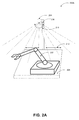
- FIGS. 2A and 2B illustrate other example configurations of one or more sensors and robotic equipment to allow implementation of sensor-based safety features
- FIG. 3 illustrates example boundary definitions
- FIG. 4 illustrates an example process to implement sensor-based safety features for robotic equipment
- FIG. 5 illustrates an example controller of a system configured to implement sensor-based safety features for robotic equipment
- FIG. 6 illustrates a general purpose computing device, which may be used to implement sensor-based safety features for robotic equipment
- FIG. 7 is a flow diagram illustrating an example process to implement sensor-based safety features for robotic equipment that may be performed by a computing device such as the computing device in FIG. 6 ;
- FIG. 8 illustrates a block diagram of an example computer program product, all arranged in accordance with at least some embodiments described herein.
- This disclosure is generally drawn, among other things, to methods, apparatus, systems, devices, and/or computer program products related to implementation of sensor-based safety features for equipment.
- One or more sensors may be positioned relative to the robotic equipment such that the sensors may capture light from at least a portion of an environment surrounding the robotic equipment.
- the sensors may be integrated with the robotic equipment and/or may be configured to rotate.
- An analysis module coupled to the sensors may build a model image of the environment based on the light captured by the sensors. The analysis module may detect that an unintended object is approaching the robotic equipment in response to detecting a change in the model image, and based on a proximity and/or a speed of approach of the object to the robotic equipment, the analysis module may instruct the robotic equipment to reduce an operating speed and/or stop motion of the robotic equipment.
- FIG. 1 illustrates an example sensor integrated with at least a portion of robotic equipment to allow implementation of sensor-based safety features, arranged in accordance with at least some embodiments described herein.
- robotic equipment 102 such as a robotic arm, may be integrated with at least one sensor 104 .
- the sensor 104 may be a complementary metal oxide semiconductor (CMOS) image sensor, a charged coupled device (CCD) image sensor, and an N-type metal oxide semiconductor (NMOS) image sensor, for example.
- CMOS complementary metal oxide semiconductor
- CCD charged coupled device
- NMOS N-type metal oxide semiconductor
- the robotic equipment 102 may include an extension shaped as a wrench, for example, and may be programmed to perform a task, such as to tighten a nut 108 in order to fasten one or more components of a part 106 together.
- a cell in which the robotic equipment 102 is located may further include one or more machines or peripherals programmed to perform the task in conjunction with the robotic equipment 102 .
- the sensor 104 may be configured to capture light from an environment surrounding the robotic equipment 102 .
- An analysis module coupled to the sensor 104 may be configured to build a model image of the environment based on the light captured by the sensors, where the model image includes the part 106 .
- the analysis module may be configured to build the model image employing one or more Gaussian distributions.
- a time variation of the model image may be stored as a plurality of frames and a comparison of the frames may be used to detect a change in the model image.
- the analysis module may be further configured to classify pixels of the model image into a foreground or a background of the model image, where pixels classified as the foreground of the model image are indicative of motion.
- the pixels classified as the foreground of the model image may be grouped, and may be representative of expected motion associated with the environment surrounding the robotic equipment 102 .
- a threshold value for a size of the group may be assigned such that unexpected motion in the environment due to an approaching object may be detected in response to the size of the group exceeding the threshold value.
- the unexpected motion may be due to an incorrect part of differing size and/or shape approaching the robotic equipment 102 , a portion of a human body approaching the robotic equipment 102 , and/or debris from other robotic equipment or machines within the cell approaching the robotic equipment 102 .
- the model image may be stored as a histogram in a database of the analysis module. The histogram may be referenced if a change in the model image is detected.
- an object such a human hand 110 may be approaching the robotic equipment 102 .
- the light captured by the sensor 104 may be analyzed by the analysis module to build the model image of the environment, and a change in the model image may be detected due to the approaching human hand 110 .
- the analysis module classifies the pixels of the model image as a foreground or a background of the model image, and groups the pixels classified as the foreground, the analysis module may determine that the size of the group exceeds the assigned threshold value.
- the analysis module may send instructions to a computing device controlling the robotic equipment 102 or directly to the robotic equipment 102 to adjust an operating speed of the robotic equipment 102 based on a proximity and/or a speed of approach of the human hand 110 to the robotic equipment 102 .
- the operating speed may be adjusted in a stepped manner or a continuous manner as the human hand 110 approaches the robotic equipment 102 , and a location of the human hand 110 within one or more defined boundaries may determine the proximity of the human hand 110 to the robotic equipment 102 on which the adjustment is based.
- a first boundary and a second boundary may be defined by an operator of the robotic equipment 102 , where the first boundary is closer in proximity to the robotic equipment 102 than the second boundary.
- the boundaries may be planar, linear, and/or three-dimensional.
- the operator may define the boundaries through a user interface provided to the operator, where the user interface is coupled to the analysis module, and may be configured to display the model image of the environment surrounding the robotic equipment 102 .
- the analysis module may instruct the robotic equipment 102 to reduce the operating speed of the robotic equipment 102 in response to detecting the human hand 110 at a location within the second boundary.
- the instruction to reduce the operating speed may be optional due to a greater distance between the human hand 110 and the robotic equipment 102 .
- the analysis module may instruct the robotic equipment 102 to stop motion in response to detecting the human hand 110 at a location within the first boundary.
- the instruction to stop motion may be mandatory due to the closer proximity of the human hand 110 to the robotic equipment 102 .
- the analysis module may instruct the robotic equipment 102 to restart motion, and/or in response to detecting the human hand 110 has left the second boundary, the analysis module may instruct the robotic equipment 102 to increase the operating speed of the robotic equipment 102 .
- the operating speed may be increased in a stepped manner or a continuous manner as the human hand 110 departs from the environment surrounding robotic equipment 102 .
- the analysis module may detect the human hand 110 is absent from the first and/or second boundary by matching a histogram of a current model image to another histogram of a last known model image in which the human hand was absent, for example, the histogram discussed in the first configuration 100 A.
- sensor-based safety features for robotic equipment as described in the above embodiments may provide a cost effective method to implement safety features for the robotic equipment to promote a safe, productive manufacturing environment.
- FIGS. 2A and 2B illustrate other example configurations of one or more sensors and robotic equipment to allow implementation of sensor-based safety features, arranged in accordance with at least some embodiments described herein.
- a sensor 204 may be positioned above robotic equipment 202 such that the sensor 204 is configured to capture light from an environment surrounding the robotic equipment.
- the sensor 204 may be positioned above the robotic equipment employing a support device 206 to which the sensor 204 may be coupled to.
- the support device 206 may be attached to a surface 208 supporting the robotic equipment 202 , as illustrated.
- the surface 208 may be a table surface, a conveyor belt surface, a work bench surface, and a wall, among other examples.
- the support device 206 may be attached to another surface, where the other surface is positioned above the robotic equipment 202 , such as a ceiling.
- the sensor may be configured to rotate 210 or the support device 206 may be portable 212 such that light may be captured from an entirety of the environment surrounding the robotic equipment 202 .
- multiple sensors 224 may be positioned relative to robotic equipment 222 such that the sensors 224 are configured to capture light from an entirety of the environment surrounding the robotic equipment 222 .
- the multiple sensors 224 may be directly attached to a surface 228 supporting the robotic equipment 222 .
- the surface 228 may be a table surface, a conveyor belt surface, a work bench surface, and a wall, among other examples.
- One or more of the multiple sensors 224 may be configured to rotate 230 .
- FIG. 3 illustrates example boundary definitions, arranged in accordance with at least some embodiments described herein.
- an operator of robotic equipment 302 integrated with a sensor 304 may define one or more boundaries, such as a first boundary 306 and a second boundary 308 , within an environment surrounding the robotic equipment 302 .
- an outlying boundary 310 may be formed comprising all other regions of the environment.
- the operator may define the boundaries through a user interface provided to the operator.
- the user interface may be coupled to an analysis module, and configured to display a model image of an environment surrounding the robotic equipment 302 built by the analysis module based on light captured by the sensor 304 . Display of the model image may provide the operator a visual representation of the environment when defining the boundaries.
- the boundaries defined may be planar, linear, and/or three-dimensional, for example. As illustrated, a distance between the first boundary 306 and the robotic equipment 302 may be less than a distance between the second boundary 308 and the robotic equipment 302 .
- a location of the object within the first boundary 306 or second boundary 308 may determine an instruction sent to the robotic equipment 302 from the analysis module to adjust an operating speed of the robotic equipment 302 .
- the analysis module may instruct the robotic equipment 302 to reduce the operating speed of the robotic equipment 302 .
- the operating speed may be reduced in a stepped manner, in a continuous manner, or in another manner. In some embodiments, the operating speed may be reduced to zero (that is, stop the robotic equipment).
- the analysis module may instruct the robotic equipment 302 to stop motion.
- the instruction may be optional, but when the object is located in the first boundary 306 , the instruction may be mandatory due to the closer proximity of the object to the robotic equipment 302 .
- no instruction may be sent to the robotic equipment 302 in response to detecting the object at a location within the outlying boundary 310 .
- a location of the object within the second boundary 308 or the outlying boundary 310 may determine an instruction sent from the analysis module to the robotic equipment 302 to resume operation of the robotic equipment 302 .
- the analysis module may instruct the robotic equipment 302 to restart motion.
- the analysis module may instruct the robotic equipment 102 to increase the operating speed of the robotic equipment 302 .
- the operating speed may be increased in a stepped, continuous, or other manner as the object departs from the environment surrounding robotic equipment 302 .
- FIG. 4 illustrates an example process to implement sensor-based safety features for equipment, arranged in accordance with at least some embodiments described herein.
- an operator 420 of robotic equipment may define one or more boundaries, such as a first boundary and a second boundary, within an environment surrounding the robotic equipment through a user interface configured to display a model image of the environment.
- the user interface may be coupled to an analysis module 424 configured to build the model image of the environment based on light captured from the environment by one or more sensors 422 at an operation 404 , “CAPTURE LIGHT AT SENSOR(S).”
- the one or more sensors 422 may be integrated with the robotic equipment and/or may be positioned separate from, but relative to, the robotic equipment such that the light is captured from at least a portion of the environment surrounding the robotic equipment. In some embodiments, the sensors 422 may be configured to rotate such that light from an entirety of the environment surrounding the robotic equipment is captured.
- the analysis module 424 may be configured to analyze the light captured from the sensors 422 .
- the analysis module 424 may classify pixels of the model image into a foreground or a background of the model image, where pixels classified as the foreground of the model image are indicative of motion. Subsequently, the pixels classified as the foreground of the model image may be grouped, and may be representative of expected motion associated with the environment surrounding the robotic equipment.
- a threshold value for a size of the group may be assigned such that unexpected motion in the environment due to an approaching object may be detected in response to the size of the group exceeding the threshold value. The unexpected motion may be due to an incorrect part or component of differing size and/or shape approaching the robotic equipment, a portion of a human body approaching the robotic equipment, and/or debris from other robotic equipment or machines, among other examples.
- the analysis module may be configured to detect if the model image has changed at an operation 408 , “DETECT CHANGE?”. If the size of the group does not exceed the threshold value, no change in the model image is detected and no further operations may be performed. If the size of the group exceeds the threshold value, a change in the model image is detected, where the change may be indicative of an unintended object approaching the robotic equipment.
- the analysis module may be configured to instruct the robotic equipment to adjust an operating speed based on a proximity and/or a speed of the approaching object. A location of the object within the first boundary or the second boundary defined by the operator at the operation 402 may determine the proximity of the object to the robotic equipment on which the adjustment is based.
- the analysis module may instruct the robotic equipment to stop motion in response to a determination that the object is detected at a location within the first boundary at decision operation 410 , “IN FIRST BOUNDARY?” due to a closer proximity of the object to the robotic equipment.
- the analysis module may instruct the robotic equipment to reduce the operating speed of the robotic equipment in response to a determination that the object is detected at a location within the second boundary at decision operation 414 , “IN SECOND BOUNDARY?” due to a greater distance between the object and the robotic equipment.
- FIG. 5 illustrates an example controller of a system configured to implement sensor-based safety features for equipment, arranged in accordance with at least some embodiments described herein.
- a system 500 may include at least one controller 520 , at imaging sub-system 530 comprising at least one imaging module 522 , and an analytics sub-system 532 comprising at least one modeling module 524 and at least one detection module 526 .
- the controller 520 may be operated by human control or may be configured for automatic operation, or may be directed by a remote controller 550 through at least one network (for example, via network 510 ). Data associated with controlling the different processes of production may be stored at and/or received from data stores 560 .
- the controller 520 may include and/or control the imaging module 522 of the imaging sub-system, the imaging module 522 configured to capture light from an environment surrounding robotic equipment through one or more sensors.
- the sensors may be integrated with the robotic equipment and/or positioned separate from, but relative, to the robotic equipment such that light from at least a portion of the environment surrounding the robotic equipment is captured.
- the sensors may be configured to rotate such that light is captured from an entirety of the environment surrounding the robotic equipment.
- the controller 520 may further include and/or control the modeling module 524 and the detection module 526 of the analytics sub-system 532 .
- the modeling module 524 may be configured to build a model image of the environment surrounding the robotic equipment based on the light captured by the sensors of the imaging module 522 .
- the model image may be stored as a histogram in a database of the analytics sub-system 532 to be referenced when a change in the model image is detected, which will be discussed below.
- the detection module 526 may be configured to detect an object approaching the robotic equipment in response to detecting a change in the model image.
- pixels of the model image may be classified into a foreground or a background of the model image, where pixels classified as the foreground of the model image are indicative of motion and grouped.
- a threshold value for a size of the group may be assigned, and in response to a determination that the size of the group has exceeded the threshold value, a change in the model image is detected that may be indicative of an object approaching the robotic equipment.
- the detection module 526 may be further configured to instruct the robotic equipment to adjust an operating speed of the robotic equipment based on a proximity and/or a speed of the approaching object to the robotic equipment.
- a location of the object within one or more boundaries defined by an operator of the robotic equipment may determine a proximity of the object to the robotic equipment on which the adjustment is based.
- the operator may define a first boundary and a second boundary within the environment surrounding the robotic equipment through a user interface configured to display the model image of the environment.
- the first boundary may be closer in proximity to the robotic equipment than the first boundary.
- the detection module may instruct the robotic equipment to reduce an operating speed of the robotic equipment.
- the operating speed may be reduced to substantially zero.
- the detection module may instruct the robotic equipment to stop motion.
- the motion may be resumed and/or the operating speed may increase upon detection that the object has left the first and/or second boundary, respectively, by the detection module 526 .
- the absence of the object may be detected by matching a histogram of a current model image to a histogram of a last known model image in which the object was absent.
- FIGS. 1 through 5 have been described using specific apparatuses, configurations, and systems to implement sensor-based safety features for equipment.
- Embodiments to implement sensor-based safety features for equipment are not limited to the specific apparatuses, configurations, and systems according to these examples.
- FIG. 6 illustrates a general purpose computing device, which may be used to implement sensor-based safety features for equipment, arranged in accordance with at least some embodiments described herein.
- the computing device 600 may be used as a server, desktop computer, portable computer, smart phone, special purpose computer, or similar devices such as a controller, a new component, a cluster of existing components in an operational system including a vehicle and a smart dwelling.
- the computing device 600 may include one or more processors 604 and a system memory 606 .
- a memory bus 608 may be used for communicating between the processor 604 and the system memory 606 .
- the basic configuration 602 is illustrated in FIG. 6 by those components within the inner dashed line.
- the processor 604 may be of any type, including but not limited to a microprocessor ( ⁇ P), a microcontroller ( ⁇ C), a digital signal processor (DSP), or any combination thereof.
- the processor 604 may include one or more levels of caching, such as a cache memory 612 , one or more processor cores 614 , and registers 616 .
- the example processor cores 614 may (each) include an arithmetic logic unit (ALU), a floating point unit (FPU), a digital signal processing core (DSP core), or any combination thereof.
- An example memory controller 618 may also be used with the processor 604 , or in some implementations, the memory controller 618 may be an internal part of the processor 604 .
- the system memory 606 may be of any type including but not limited to volatile memory (such as RAM), non-volatile memory (such as ROM, flash memory, etc.) or any combination thereof.
- the system memory 606 may include an operating system 620 , a controller application 622 , and program data 624 .
- the controller application 622 may include an imaging module 626 and an analysis module 627 , which may be an integral part of the application or a separate application on its own.
- the imaging module 626 may be configured to capture light from an environment surrounding robotic equipment.
- the analysis module 627 may be configured to build a model image of the environment surrounding the robotic equipment based on the light captured by the sensors of the imaging module 626 , detect an object approaching the robotic equipment in response to a detection of a change in the model image, and instruct the robotic equipment to adjust an operating speed of the robotic equipment based on a proximity and/or speed of approach of the object to the robotic equipment.
- the program data 624 may include, among other data, process data 628 related to building the model image and detecting a change in the model image, as described herein.
- the computing device 600 may have additional features or functionality, and additional interfaces to facilitate communications between the basic configuration 602 and any desired devices and interfaces.
- a bus/interface controller 630 may be used to facilitate communications between the basic configuration 602 and one or more data storage devices 632 via a storage interface bus 634 .
- the data storage devices 632 may be one or more removable storage devices 636 , one or more non-removable storage devices 638 , or a combination thereof.
- Examples of the removable storage and the non-removable storage devices include magnetic disk devices such as flexible disk drives and hard-disk drives (HDD), optical disk drives such as compact disc (CD) drives or digital versatile disk (DVD) drives, solid state drives (SSDs), and tape drives to name a few.
- Example computer storage media may include volatile and non-volatile, removable and non-removable media implemented in any method or technology for storage of information, such as computer readable instructions, data structures, program modules, or other data.
- the system memory 606 , the removable storage devices 636 and the non-removable storage devices 638 are examples of computer storage media.
- Computer storage media includes, but is not limited to, RAM, ROM, EEPROM, flash memory or other memory technology, CD-ROM, digital versatile disks (DVDs), solid state drives (SSDs), or other optical storage, magnetic cassettes, magnetic tape, magnetic disk storage or other magnetic storage devices, or any other medium which may be used to store the desired information and which may be accessed by the computing device 600 . Any such computer storage media may be part of the computing device 600 .
- the computing device 600 may also include an interface bus 640 for facilitating communication from various interface devices (for example, one or more output devices 642 , one or more peripheral interfaces 644 , and one or more communication devices 646 ) to the basic configuration 602 via the bus/interface controller 630 .
- interface devices for example, one or more output devices 642 , one or more peripheral interfaces 644 , and one or more communication devices 646 .
- Some of the example output devices 642 include a graphics processing unit 648 and an audio processing unit 650 , which may be configured to communicate to various external devices such as a display or speakers via one or more A/V ports 652 .
- One or more example peripheral interfaces 644 may include a serial interface controller 654 or a parallel interface controller 656 , which may be configured to communicate with external devices such as input devices (for example, keyboard, mouse, pen, voice input device, touch input device, etc.) or other peripheral devices (for example, printer, scanner, etc.) via one or more I/O ports 658 .
- An example communication device 646 includes a network controller 660 , which may be arranged to facilitate communications with one or more other computing devices 662 over a network communication link via one or more communication ports 664 .
- the one or more other computing devices 662 may include servers, client devices, and comparable devices.
- the network communication link may be one example of a communication media.
- Communication media may typically be embodied by computer readable instructions, data structures, program modules, or other data in a modulated data signal, such as a carrier wave or other transport mechanism, and may include any information delivery media.
- a “modulated data signal” may be a signal that has one or more of its characteristics set or changed in such a manner as to encode information in the signal.
- communication media may include wired media such as a wired network or direct-wired connection, and wireless media such as acoustic, radio frequency (RF), microwave, infrared (IR) and other wireless media.
- RF radio frequency
- IR infrared
- the term computer readable media as used herein may include both storage media and communication media.
- the computing device 600 may be implemented as a part of a general purpose or specialized server, mainframe, or similar computer that includes any of the above functions.
- the computing device 600 may also be implemented as a personal computer including both laptop computer and non-laptop computer configurations.
- Example embodiments may also include methods to implement sensor-based safety features for equipment. These methods can be implemented in any number of ways, including the structures described herein. One such way may be by machine operations, of devices of the type described in the present disclosure. Another optional way may be for one or more of the individual operations of the methods to be performed in conjunction with one or more human operators performing some of the operations while other operations may be performed by machines. These human operators need not be collocated with each other, but each can be only with a machine that performs a portion of the program. In other embodiments, the human interaction can be automated such as by pre-selected criteria that may be machine automated.
- FIG. 7 is a flow diagram illustrating an example process to implement sensor-based safety features for equipment that may be performed by a computing device such as the computing device in FIG. 6 , arranged in accordance with at least some embodiments described herein.
- Example methods may include one or more operations, functions or actions as illustrated by one or more of blocks 722 , 724 , and/or 726 .
- the operations described in the blocks 722 through 726 may also be stored as computer-executable instructions in a computer-readable medium such as a computer-readable medium 720 of a computing device 710 .
- An example process to implement sensor-based safety features for robotic equipment may begin with block 722 , “BUILD A MODEL IMAGE OF AN ENVIRONMENT SURROUNDING ROBOTIC EQUIPMENT BASED ON LIGHT CAPTURED BY ONE OR MORE SENSORS,” where one or more sensors may capture light from an environment surrounding robotic equipment.
- the sensors may be integrated with the robotic equipment and/or positioned separate from, but relative to, the robotic equipment such that light from at least a portion of the environment surrounding the robotic equipment is captured.
- Example sensors may include CMOS image sensors, CCD image sensors, and NMOS image sensors.
- An analysis module coupled to the one or more sensors may be configured to build a model image of the environment surrounding the robotic equipment based on the light captured by the sensors.
- the analysis module may employ Gaussian distributions to build the model image.
- the model image may be stored as a histogram in a database of the analysis module to be referenced in response to a detected change in the model image.
- Block 722 may be followed by block 724 , “DETECT AN OBJECT APPROACHING THE ROBOTIC EQUIPMENT IN RESPONSE TO DETECTION OF A CHANGE IN THE MODEL IMAGE,” where the analysis module may classify pixels of the model image into a foreground or a background of the model image, where pixels classified as the foreground of the model image are indicative of motion and grouped.
- a threshold value for a size of the group may be assigned, and in response to a determination that the size of the group has exceeded the threshold value, a change in the model image is detected that may be indicative of an object approaching the robotic equipment.
- the object approaching the robotic equipment may be an incorrect part or component of differing size and/or shape, a portion of a human body, and/or debris from one or more other machines in the environment.
- Block 724 may be followed by block 726 , “INSTRUCT THE ROBOTIC EQUIPMENT TO ADJUST AN OPERATING SPEED OF THE ROBOTIC EQUIPMENT BASED ON ONE OR MORE OF A PROXIMITY AND A SPEED OF APPROACH OF THE OBJECT TO THE ROBOTIC EQUIPMENT,” where the analysis module may be further configured to instruct the robotic equipment to adjust an operating speed of the robotic equipment based on a proximity and/or a speed of approach of the object to the robotic equipment. A location of the object within one or more boundaries defined by an operator of the robotic equipment may determine a proximity of the object to the robotic equipment on which the adjustment is based.
- the operator may define a first boundary and a second boundary within the environment surrounding the robotic equipment through a user interface configured to display the model image of the environment.
- the first boundary may be closer in proximity to the robotic equipment than the first boundary.
- the analysis module may instruct the robotic equipment to reduce an operating speed of the robotic equipment. In some examples, the operating speed may be reduced to substantially zero.
- the analysis module may instruct the robotic equipment to stop motion. The motion may be resumed and/or the operating speed may increase upon detection that the object has left the first and/or second boundary, respectively, by the detection module.
- the absence of the object may be detected by matching a histogram of a current model image to a histogram of a last known model image in which the object was absent.
- FIG. 8 illustrates a block diagram of an example computer program product, arranged in accordance with at least some embodiments described herein.
- the computer program product 800 may include a signal bearing medium 802 that may also include one or more machine readable instructions 804 that, when executed by, for example, a processor, may provide the functionality described herein.
- a processor may provide the functionality described herein.
- imaging module 626 and analysis module 627 executed on the processor 604 may undertake one or more of the tasks shown in FIG. 8 in response to the instructions 804 conveyed to the processor 604 by the signal bearing medium 802 to perform actions associated with implementation of sensor-based safety features for equipment as described herein.
- Some of those instructions may include, for example, one or more instructions to build a model image of an environment surrounding robotic equipment based on light captured by one or more sensors, detect an object approaching the robotic equipment in response to detection of a change in the model image, and instruct the robotic equipment to adjust an operating speed of the robotic equipment based on one or more of a proximity and a speed of approach of the object to the robotic equipment.
- the signal bearing medium 802 depicted in FIG. 8 may encompass a computer-readable medium 806 , such as, but not limited to, a hard disk drive (HDD), a solid state drive (SSD), a Compact Disc (CD), a Digital Versatile Disk (DVD), a digital tape, memory, etc.
- the signal bearing medium 802 may encompass a recordable medium 808 , such as, but not limited to, memory, read/write (R/W) CDs, R/W DVDs, etc.
- the signal bearing medium 802 may encompass a communications medium 810 , such as, but not limited to, a digital and/or an analog communication medium (for example, a fiber optic cable, a waveguide, a wired communication link, a wireless communication link, etc.).
- a communications medium 810 such as, but not limited to, a digital and/or an analog communication medium (for example, a fiber optic cable, a waveguide, a wired communication link, a wireless communication link, etc.).
- the computer program product 800 may be conveyed to one or more modules of the processor 604 of FIG. 6 by an RF signal bearing medium, where the signal bearing medium 802 is conveyed by the wireless communications medium 810 (for example, a wireless communications medium conforming with the IEEE 802.11 standard).
- Example methods may include generating a model image of an environment surrounding the robotic equipment based on light captured by one or more sensors, where a time variation of the model image is stored as a plurality of frames; detecting a change in the model image based on a comparison of one or more frames; and determining whether an unintended object is approaching the robotic equipment based on the detected change.
- Example methods may also include instructing the robotic equipment to adjust an operating speed of the robotic equipment based on one or more of a proximity and a speed of approach of the object to the robotic equipment in response to a determination that the unintended object is approaching the robotic equipment.
- the methods may further include determining the one or more of the proximity and the speed of approach of the object to the robotic equipment based on the comparison of the one or more frames, or classifying pixels of the model image into one of a foreground and a background of the model image.
- the methods may also include grouping the pixels classified as the foreground of the model image, where the grouped pixels classified as the foreground of the model image are indicative of motion.
- the methods may further include assigning a threshold value for a size of the grouped pixels. Detecting the change in the model image may include determining that the size of the grouped pixels exceeds the threshold value.
- instructing the robotic equipment to adjust the operating speed of the robotic equipment may include instructing the robotic equipment to reduce the operating speed of the robotic equipment to substantially zero or instructing the robotic equipment to bring the robotic equipment to a stop.
- the methods may further include receiving, from an operator of the robotic equipment through a user interface displaying the model image, a definition of at least a first boundary and a second boundary within the environment surrounding the robotic equipment. A distance between the first boundary and the robotic equipment may be less than a distance between the second boundary and the robotic equipment.
- Instructing the robotic equipment may include instructing the robotic equipment to stop motion in response to detecting the object at a location between the first boundary and the robotic equipment or instructing the robotic equipment to reduce the operating speed of the robotic equipment in response to detecting the object at a location between the second boundary and the first boundary.
- instructing the robotic equipment may include instructing the robotic equipment to restart motion in response to detecting the object leave the first boundary or instructing the robotic equipment to increase the operating speed of the robotic equipment in response to detecting the object leave the second boundary.
- Detecting the object leave the second boundary may include storing the plurality of frames as histograms and determining an absence of the object in response to determining that a histogram of a current frame matches a histogram of a last known frame in which the object was absent within the second boundary.
- An apparatus configured to implement sensor-based safety features for robotic equipment.
- An example apparatus may include one or more sensors configured to capture light from an environment surrounding the robotic equipment and at least one analysis module communicatively coupled to the one or more sensors.
- the at least one analysis module may be configured to generate a model image of an environment surrounding the robotic equipment based on the light captured by the one or more sensors, where a time variation of the model image is stored as a plurality of frames; detect a change in the model image based on a comparison of one or more frames; and determine whether an unintended object is approaching the robotic equipment based on the detected change.
- the at least one analysis module may also be configured to instruct the robotic equipment to adjust an operating speed of the robotic equipment based on one or more of a proximity and a speed of approach of the object to the robotic equipment in response to a determination that the unintended object is approaching the robotic equipment.
- the one or more sensors may include complementary metal oxide semiconductor (CMOS) image sensors, charged coupled device (CCD) image sensors, or N-type metal oxide semiconductor (NMOS) image sensors.
- CMOS complementary metal oxide semiconductor
- CCD charged coupled device
- NMOS N-type metal oxide semiconductor
- the one or more sensors may be positioned at one or more locations relative to the robotic equipment such that the light is captured from at least one portion of the environment surrounding the robotic equipment.
- the one or more sensors may be integrated with the robotic equipment.
- the one or more sensors may be positioned or configured to rotate such that the light is captured from substantially an entirety of the environment surrounding the robotic equipment.
- the at least one analysis module may be configured to generate the model image employing one or more Gaussian distributions.
- the apparatus may also include a user interface coupled to the at least one analysis module, the user interface configured to display the model image of the environment surrounding the robotic equipment to an operator of the robotic equipment.
- the at least one analysis module may be further configured to receive, from the operator of the robotic equipment, a definition of at least a first boundary and a second boundary within the environment surrounding the robotic equipment.
- the at least one analysis module may also be configured to determine the proximity of the object to the robotic equipment based on a location of the object within the first boundary or the second boundary.
- the system may include at least one imaging module configured to capture light of an environment surrounding the robotic equipment through one or more sensors; at least one modeling module configured to generate a model image of an environment surrounding the robotic equipment based on the light captured by the at least one imaging module, where a time variation of the model image is stored as a plurality of frames; and at least one detection module configured to detect a change in the model image based on a comparison of one or more frames and determine whether an unintended object is approaching the robotic equipment based on the detected change.
- the system may also include at least one controller configured to instruct the robotic equipment to adjust an operating speed of the robotic equipment based on one or more of a proximity and a speed of approach of the object to the robotic equipment in response to a determination that the unintended object is approaching the robotic equipment.
- the at least one controller may be further configured to control operational aspects of the at least one imaging module, the at least one modeling module, and the at least one detection module.
- the at least one modeling module may be further configured to classify pixels of the model image into one of a foreground and a background of the model image; group the pixels classified as the foreground of the model image; and assign a threshold value for a size of the grouped pixels.
- the at least one detection module may be further configured to determine that the size of the grouped pixels exceeds the threshold value in order to detect the change in the model image.
- Example 1 Detection of a Human Hand within a First Boundary by a Sensor Positioned Above a Robotic Quilting Machine in a Textile Manufacturing Plant
- a single NMOS sensor coupled to a support device is positioned above a robotic quilting machine configured to fabricate a material composed of three layers of fiber.
- the support device is attached to a component of the robotic quilting machine.
- the single sensor is configured to capture light from an environment of the robotic quilting machine, and is further configured to rotate to ensure light is captured from an entirety of the environment.
- An analysis module coupled to the sensor is configured to build a model image based on the captured light from the environment.
- the model image includes the layers of fiber used to fabricate the material and one or more other machines and/or peripherals configured to perform the fabrication in conjunction with the robotic quilting machine.
- the model image is saved as a histogram within a database of the analysis module to be referenced in response to a detection of a change in the model image.
- a user interface coupled to the analysis module provides a display of the model image to an operator of the robotic quilting machine and allows the operator to define a first boundary and a second boundary within the environment.
- the first boundary is an area of the environment within 10 centimeters (cm) of the robotic quilting machine and the second boundary is an area of the environment from 10 cm to 40 cm of the robotic quilting machine.
- the analysis module classifies pixels within the model image into a foreground and/or a background of the model image.
- the pixels classified as the foreground of the model image is grouped together and are indicative of motion associated with the environment of the robotic quilting device. For example, the motion of feeding the layers of fiber used to fabricate the material into the robotic quilting machine and the motion of the one or more other machines and/or peripherals configured to perform the fabrication in conjunction with the robotic quilting machine.
- a size of the group is assigned a threshold value.
- the analysis module detects a change in the model image in response to a determination that the size of the group exceeds the threshold value due to unexpected motion in the environment, where the change is indicative of a human hand approaching the robotic quilting machine.
- the human hand is determined to be located 3 cm above the robotic quilting machine within the first boundary.
- the analysis module is configured to instruct the robotic quilting machine to stop motion based on the location of the human hand in the first boundary. Once the analysis module detects the human hand moves to a location 11 cm above the robotic quilting machine within the second boundary, the analysis module instructs the robotic quilting machine to restart the motion of the robotic quilting machine. Furthermore, once the analysis module detects the human hand moves to a location 41 cm above the robotic quilting machine outside of the second boundary, the analysis module is configured to increase an operating speed of the robotic quilting machine. The analysis module detects the absence of the human hand from the first and/or second boundaries by matching a histogram of a current model image with a histogram of a last known model image in which the human hand was absent.
- Example 2 Detection of Incorrect Component within a Second Boundary by a Sensor Integrated with Robotic Welder in a Car Manufacturing Plant
- a single CMOS image sensor is integrated with a robotic welder configured to weld together two or more floor pan components of a vehicle.
- the single sensor is configured to capture light from an environment of the robotic welder, and is further be configured to rotate such that light is captured from an entirety of the environment.
- An analysis module coupled to the sensor is configured to build a model image based on the captured light from the environment.
- the model image includes the floor pan components to be welded together and one or more other machines and/or peripherals configured to perform the welding in conjunction with the robotic welder.
- the model image is saved as a histogram within a database of the analysis module to be referenced in response to a detection of a change in the model image.
- a user interface coupled to the analysis module provides a display of the model image to an operator of the robotic welder and allows the operator to define a first boundary and a second boundary within the environment.
- the first boundary is an area of the environment within 1 meter (m) of the robotic welder and the second boundary is an area of the environment from 1 m to 2 m of the robotic welder.
- the analysis module classifies pixels within the model image into a foreground and/or a background of the model image.
- the pixels classified as the foreground of the model image are grouped together and are indicative of motion associated with the environment of the robotic welder. For example, the motion of the approaching floor pan components to be welded together and one or more other machines and/or peripherals configured to perform the welding in conjunction with the robotic welder.
- a size of the group is assigned a threshold value.
- the analysis module detects a change in the model image in response to a determination that the size of the group exceeds the threshold value due to unexpected motion in the environment, where the change is indicative of an incorrect component, such as a suspension, approaching the robotic welder.
- the suspension is determined to be located 1.5 m away from the robotic welder within the second boundary.
- the analysis module is configured to instruct the robotic welder to reduce an operating speed of welding based on the location of the suspension in the second boundary. Once the analysis module detects the suspension move to a location greater than 2 m away from the robotic welder outside the second boundary, the analysis module instructs the robotic welder to increase the operating speed of welding. The analysis module detects the absence of the suspension from the second boundary by matching a histogram of a current model image with a histogram of a last known model image in which the suspension was absent.
- Example 3 Detection of Debris within a First and Second Boundary by Multiple Sensors Positioned Around a Robotic Etcher in an Electronics Manufacturing Plant
- CCD image sensors are positioned around a robotic etcher configured to etch one or more optical components onto a surface of an integrated circuit (IC).
- the sensors are positioned on a same surface supporting the robotic etcher.
- the sensors are configured to capture light from an environment of the robotic etcher, and are further configured to rotate to ensure light is captured from an entirety of the environment.
- An analysis module coupled to the sensor is configured to build a model image based on the captured light from the environment.
- the model image includes the IC, the one or more optical components, and one or more other machines and/or peripherals configured to perform the etching in conjunction with the robotic etcher.
- the model image is saved as a histogram within a database of the analysis module to be referenced in response to a detection of a change in the model image.
- a user interface coupled to the analysis module provides a display of the model image to an operator of the robotic etcher and allows the operator to define a first boundary and a second boundary within the environment.
- the first boundary is an area of the environment within 10 millimeters (mm) of the robotic quilting machine and the second boundary is an area of the environment from 10 mm to 40 mm of the robotic etcher.
- the analysis module classifies pixels within the model image into a foreground and/or a background of the model image.
- the pixels classified as the foreground of the model image are grouped together and are indicative of motion associated with the environment of the robotic etcher. For example, the motion of the IC approaching the robotic etcher to allow the etching of the one or more optical components onto the IC and the motion of the one or more other machines and/or peripherals configured to perform the etching in conjunction with the robotic etcher.
- a size of the group is assigned a threshold value.
- the analysis module detects a change in the model image in response to a determination that the size of the group exceeds the threshold value due to unexpected motion in the environment, where the change is indicative of debris approaching the robotic etcher, where the debris is excess material from a previous manufacturing process to fabricate the IC.
- the debris is determined to be located 35 mm from the robotic etcher within the second boundary.
- the analysis module is configured to instruct the robotic etcher to reduce an operating speed in a continuous manner based on the location of the debris in the second boundary.
- the debris continues to approach the robotic etcher and is determined to be located 5 mm from the robotic etcher within the first boundary.
- the analysis module is configured to instruct the robotic etcher to stop motion based on the location of the debris in the first boundary.
- the analysis module detects the debris move to a location 10 mm away from the robotic etcher within the second boundary, the analysis module instructs the robotic etcher to restart the motion of the robotic etcher. Furthermore, once the analysis module detects the debris move to a location 40 mm away from the robotic etcher outside of the second boundary, the analysis module is configured to increase an operating speed of the robotic etcher. The analysis module detects the absence of the debris from the first and/or second boundaries by matching a histogram of a current model image with a histogram of a last known model image in which the debris was absent.
- compositions, methods, systems, and devices are described in terms of “comprising” various components or steps (interpreted as meaning “including, but not limited to”), the compositions, methods, systems, and devices can also “consist essentially of” or “consist of the various components and steps, and such terminology should be interpreted as defining essentially closed-member groups.”
- a signal bearing medium examples include, but are not limited to, the following: a recordable type medium such as a floppy disk, a hard disk drive (HDD), a Compact Disc (CD), a Digital Versatile Disk (DVD), a digital tape, a computer memory, etc.; and a transmission type medium such as a digital and/or an analog communication medium (for example, a fiber optic cable, a waveguide, a wired communication link, a wireless communication link, etc.).
- a typical data processing system generally includes one or more of a system unit housing, a video display device, a memory such as volatile and non-volatile memory, processors such as microprocessors and digital signal processors, computational entities such as operating systems, drivers, graphical user interfaces, and applications programs, one or more interaction devices, such as a touch pad or screen, and/or control systems including feedback loops.
- any two components so associated may also be viewed as being “operably connected”, or “operably coupled”, to each other to achieve the particular functionality, and any two components capable of being so associated may also be viewed as being “operably couplable”, to each other to achieve the particular functionality.
- operably couplable include but are not limited to physically connectable and/or physically interacting components and/or wirelessly interactable and/or wirelessly interacting components and/or logically interacting and/or logically interactable components.
- a range includes each individual member.
- a group having 1-3 cells refers to groups having 1, 2, or 3 cells.
- a group having 1-5 cells refers to groups having 1, 2, 3, 4, or 5 cells, and so forth.
Landscapes
- Engineering & Computer Science (AREA)
- Human Computer Interaction (AREA)
- Manufacturing & Machinery (AREA)
- Physics & Mathematics (AREA)
- General Physics & Mathematics (AREA)
- Automation & Control Theory (AREA)
- Robotics (AREA)
- Mechanical Engineering (AREA)
- Manipulator (AREA)
- Image Analysis (AREA)
Applications Claiming Priority (1)
| Application Number | Priority Date | Filing Date | Title |
|---|---|---|---|
| PCT/US2014/050405 WO2016022155A1 (en) | 2014-08-08 | 2014-08-08 | Sensor-based safety features for robotic equipment |
Publications (2)
| Publication Number | Publication Date |
|---|---|
| US20160224012A1 US20160224012A1 (en) | 2016-08-04 |
| US9740193B2 true US9740193B2 (en) | 2017-08-22 |
Family
ID=55264277
Family Applications (1)
| Application Number | Title | Priority Date | Filing Date |
|---|---|---|---|
| US14/432,732 Active 2034-10-17 US9740193B2 (en) | 2014-08-08 | 2014-08-08 | Sensor-based safety features for robotic equipment |
Country Status (3)
| Country | Link |
|---|---|
| US (1) | US9740193B2 (zh) |
| CN (2) | CN111240269B (zh) |
| WO (1) | WO2016022155A1 (zh) |
Cited By (5)
| Publication number | Priority date | Publication date | Assignee | Title |
|---|---|---|---|---|
| US10099372B2 (en) | 2017-02-07 | 2018-10-16 | Veo Robotics, Inc. | Detecting and classifying workspace regions for safety monitoring |
| US20210370512A1 (en) * | 2018-09-28 | 2021-12-02 | Still Gmbh | Method for Safeguarding the Work Area of a Mobile Logistics Robot Using Adaptive Protection Zones |
| US11518051B2 (en) | 2017-02-07 | 2022-12-06 | Veo Robotics, Inc. | Dynamic, interactive signaling of safety-related conditions in a monitored environment |
| US11541543B2 (en) | 2017-02-07 | 2023-01-03 | Veo Robotics, Inc. | Dynamic, interactive signaling of safety-related conditions in a monitored environment |
| US11820025B2 (en) | 2017-02-07 | 2023-11-21 | Veo Robotics, Inc. | Safe motion planning for machinery operation |
Families Citing this family (21)
| Publication number | Priority date | Publication date | Assignee | Title |
|---|---|---|---|---|
| US10274930B2 (en) * | 2015-08-03 | 2019-04-30 | Siemens Aktiengesellschaft | Machine human interface—MHI |
| US10416614B2 (en) | 2015-10-15 | 2019-09-17 | Siemens Aktiengesellschaft | Human programming interfaces for machine-human interfaces |
| DE102016203701A1 (de) * | 2016-03-07 | 2017-09-07 | Kuka Roboter Gmbh | Industrieroboter mit mindestens zwei Bilderfassungseinrichtungen |
| US10016896B2 (en) * | 2016-06-30 | 2018-07-10 | Brain Corporation | Systems and methods for robotic behavior around moving bodies |
| EP3360652B1 (en) * | 2017-02-14 | 2020-07-15 | Sony Corporation | Detection of engagement of robot with object |
| JP2018176397A (ja) * | 2017-04-21 | 2018-11-15 | オムロン株式会社 | ロボットシステム |
| JP6953778B2 (ja) * | 2017-04-28 | 2021-10-27 | オムロン株式会社 | 協調ロボット、コントローラ、および方法 |
| JP7329902B2 (ja) * | 2017-08-25 | 2023-08-21 | オムロン株式会社 | ロボット制御装置、ロボットシステム、ロボット制御方法、および、ロボット制御プログラム |
| DE102018214439A1 (de) * | 2017-11-17 | 2019-05-23 | Volkswagen Aktiengesellschaft | Verfahren und Vorrichtung zur Absicherung eines Arbeitsbereiches eines Roboters während einer Benutzungsphase |
| JP6680752B2 (ja) * | 2017-11-28 | 2020-04-15 | ファナック株式会社 | ロボットの速度を制限する制御装置 |
| CN111491766A (zh) * | 2017-12-21 | 2020-08-04 | 麦格纳国际公司 | 用于机器人组件的安全控制模块及其方法 |
| JP6687654B2 (ja) * | 2018-03-14 | 2020-04-28 | ファナック株式会社 | 協働ロボットの制御装置及び制御方法 |
| JP2019188556A (ja) * | 2018-04-26 | 2019-10-31 | オムロン株式会社 | センサコントローラ、ロボットシステム、センサ制御方法、およびプログラム |
| EP3784449A1 (en) * | 2018-05-30 | 2021-03-03 | Sony Corporation | Control apparatus, control method, robot apparatus and program |
| WO2022016152A1 (en) | 2020-07-17 | 2022-01-20 | Path Robotics, Inc. | Real time feedback and dynamic adjustment for welding robots |
| CA3211502A1 (en) | 2021-02-24 | 2022-09-01 | Path Robotics, Inc. | Autonomous welding robots |
| US11897706B2 (en) | 2021-03-30 | 2024-02-13 | Dexterity, Inc. | Robotic system with zone-based control |
| US11981517B2 (en) * | 2021-03-30 | 2024-05-14 | Dexterity, Inc. | Robotic line kitting system safety features |
| US20230333254A1 (en) * | 2022-04-15 | 2023-10-19 | Zebra Technologies Corporation | Lidar Sensor System for Enabling or Disabling Use of a Robotic Arm |
| US20230330764A1 (en) * | 2022-04-19 | 2023-10-19 | Path Robotics, Inc. | Autonomous assembly robots |
| GB2622565A (en) * | 2022-07-15 | 2024-03-27 | Taylor Hobson Ltd | A collision protection apparatus |
Citations (8)
| Publication number | Priority date | Publication date | Assignee | Title |
|---|---|---|---|---|
| US4967370A (en) * | 1988-10-21 | 1990-10-30 | Robotic Vision Systems, Inc. | Robot and sensor error determination system |
| US20010041077A1 (en) * | 2000-01-07 | 2001-11-15 | Werner Lehner | Apparatus and method for monitoring a detection region of a working element |
| US20050207619A1 (en) * | 2003-12-20 | 2005-09-22 | Leuze Lumiflex Gmbh & Co., Kg | Device for monitoring an area of coverage on a work tool |
| US7024278B2 (en) * | 2002-09-13 | 2006-04-04 | Irobot Corporation | Navigational control system for a robotic device |
| US20090088634A1 (en) | 2007-09-30 | 2009-04-02 | Intuitive Surgical, Inc. | Tool tracking systems and methods for image guided surgery |
| US20090222134A1 (en) | 2006-07-31 | 2009-09-03 | Andre Franke | Camera-based monitoring of machines with mobile machine elements for collision prevention |
| US20090268029A1 (en) * | 2006-11-24 | 2009-10-29 | Joerg Haussmann | Method and apparatus for monitoring a three-dimensional spatial area |
| US20120327190A1 (en) * | 2010-02-23 | 2012-12-27 | Ifm Electronic Gmbh | Monitoring system |
Family Cites Families (2)
| Publication number | Priority date | Publication date | Assignee | Title |
|---|---|---|---|---|
| WO2008004487A1 (fr) * | 2006-07-04 | 2008-01-10 | Panasonic Corporation | Appareil et procédé de commande de bras robotisé, robot et programme de commande de bras robotisé |
| CN103268616B (zh) * | 2013-04-18 | 2015-11-25 | 北京工业大学 | 多特征多传感器的移动机器人运动人体跟踪方法 |
-
2014
- 2014-08-08 US US14/432,732 patent/US9740193B2/en active Active
- 2014-08-08 CN CN202010043682.XA patent/CN111240269B/zh active Active
- 2014-08-08 WO PCT/US2014/050405 patent/WO2016022155A1/en active Application Filing
- 2014-08-08 CN CN201480082555.3A patent/CN107003656B/zh active Active
Patent Citations (8)
| Publication number | Priority date | Publication date | Assignee | Title |
|---|---|---|---|---|
| US4967370A (en) * | 1988-10-21 | 1990-10-30 | Robotic Vision Systems, Inc. | Robot and sensor error determination system |
| US20010041077A1 (en) * | 2000-01-07 | 2001-11-15 | Werner Lehner | Apparatus and method for monitoring a detection region of a working element |
| US7024278B2 (en) * | 2002-09-13 | 2006-04-04 | Irobot Corporation | Navigational control system for a robotic device |
| US20050207619A1 (en) * | 2003-12-20 | 2005-09-22 | Leuze Lumiflex Gmbh & Co., Kg | Device for monitoring an area of coverage on a work tool |
| US20090222134A1 (en) | 2006-07-31 | 2009-09-03 | Andre Franke | Camera-based monitoring of machines with mobile machine elements for collision prevention |
| US20090268029A1 (en) * | 2006-11-24 | 2009-10-29 | Joerg Haussmann | Method and apparatus for monitoring a three-dimensional spatial area |
| US20090088634A1 (en) | 2007-09-30 | 2009-04-02 | Intuitive Surgical, Inc. | Tool tracking systems and methods for image guided surgery |
| US20120327190A1 (en) * | 2010-02-23 | 2012-12-27 | Ifm Electronic Gmbh | Monitoring system |
Non-Patent Citations (1)
| Title |
|---|
| International Search Report and Written Opinion for International Application No. PCT/US2014/050405 mailed Dec. 16, 2014. |
Cited By (12)
| Publication number | Priority date | Publication date | Assignee | Title |
|---|---|---|---|---|
| US10099372B2 (en) | 2017-02-07 | 2018-10-16 | Veo Robotics, Inc. | Detecting and classifying workspace regions for safety monitoring |
| US10882185B2 (en) | 2017-02-07 | 2021-01-05 | Veo Robotics, Inc. | Dynamically determining workspace safe zones with speed and separation monitoring |
| US10899007B2 (en) | 2017-02-07 | 2021-01-26 | Veo Robotics, Inc. | Ensuring safe operation of industrial machinery |
| US11040450B2 (en) | 2017-02-07 | 2021-06-22 | Veo Robotics, Inc. | Dynamically determining and monitoring workspace safe zones using semantic representations of workpieces |
| US11279039B2 (en) | 2017-02-07 | 2022-03-22 | Veo Robotics, Inc. | Ensuring safe operation of industrial machinery |
| US11376741B2 (en) | 2017-02-07 | 2022-07-05 | Veo Robotics, Inc. | Dynamically determining workspace safe zones with speed and separation monitoring |
| US11518051B2 (en) | 2017-02-07 | 2022-12-06 | Veo Robotics, Inc. | Dynamic, interactive signaling of safety-related conditions in a monitored environment |
| US11541543B2 (en) | 2017-02-07 | 2023-01-03 | Veo Robotics, Inc. | Dynamic, interactive signaling of safety-related conditions in a monitored environment |
| US11623356B2 (en) | 2017-02-07 | 2023-04-11 | Veo Robotics, Inc. | Dynamic, interactive signaling of safety-related conditions in a monitored environment |
| US11820025B2 (en) | 2017-02-07 | 2023-11-21 | Veo Robotics, Inc. | Safe motion planning for machinery operation |
| US20210370512A1 (en) * | 2018-09-28 | 2021-12-02 | Still Gmbh | Method for Safeguarding the Work Area of a Mobile Logistics Robot Using Adaptive Protection Zones |
| US11833693B2 (en) * | 2018-09-28 | 2023-12-05 | Still Gmbh | Method for safeguarding the work area of a mobile logistics robot using adaptive protection zones |
Also Published As
| Publication number | Publication date |
|---|---|
| CN107003656B (zh) | 2020-02-07 |
| CN107003656A (zh) | 2017-08-01 |
| US20160224012A1 (en) | 2016-08-04 |
| CN111240269A (zh) | 2020-06-05 |
| CN111240269B (zh) | 2023-12-08 |
| WO2016022155A1 (en) | 2016-02-11 |
Similar Documents
| Publication | Publication Date | Title |
|---|---|---|
| US9740193B2 (en) | Sensor-based safety features for robotic equipment | |
| EP3563270B1 (en) | System and method for providing variation in bead size to improve geometrical accuracy of deposited layers in an additive manufacturing process | |
| EP2667291A1 (en) | Method and apparatus for moving an object | |
| US20160042517A1 (en) | Detection and tracking of item features | |
| IN2014CN02676A (zh) | ||
| US11631005B2 (en) | Method and apparatus for detecting small objects with an enhanced deep neural network | |
| US20180245923A1 (en) | Electronic machine equipment | |
| TW200721039A (en) | Imaging system, processing method for the imaging system, and program for making computer execute the processing method | |
| US20150005915A1 (en) | Computing device and method for generating manufacturing program of product for cnc machine | |
| US11490217B2 (en) | Audio rendering for augmented reality | |
| KR101623642B1 (ko) | 로봇 청소기, 단말장치의 제어방법 및 이를 포함하는 로봇 청소기 제어 시스템 | |
| US10769808B2 (en) | Apparatus and methods of automated tracking and counting of objects on a resource-constrained device | |
| US11720814B2 (en) | Method and system for classifying time-series data | |
| WO2015099927A1 (en) | Audio data detection with a computing device | |
| US20140362109A1 (en) | Method for transforming an object and electronic device thereof | |
| CN116324682A (zh) | 至少部分地基于用户眼睛移动的功率控制 | |
| US20150220153A1 (en) | Gesture recognition system with finite state machine control of cursor detector and dynamic gesture detector | |
| EP2587349A3 (en) | Information processing program, information processing system, and information processing method | |
| US9956661B2 (en) | Feedback control numerical machine tool and method thereof | |
| EP1686579A3 (en) | Data Processing circuit, data processing apparatus, data processing method, data processing control method, recording medium on which data processing program is stored and recording medium on which data processing control program is stored | |
| Costi et al. | Comparative analysis of model-based predictive shared control for delayed operation in object reaching and recognition tasks with tactile sensing | |
| CN102693412A (zh) | 用于检测物件的影像处理方法及影像处理装置 | |
| US10525599B1 (en) | Automatic detection of screen area and camera assisted movement of robotic arm | |
| US20220364423A1 (en) | Methods and systems for controlling operation of wireline cable spooling equipment | |
| WO2019093297A1 (ja) | 情報処理装置、制御方法、及びプログラム |
Legal Events
| Date | Code | Title | Description |
|---|---|---|---|
| AS | Assignment |
Owner name: EMPIRE TECHNOLOGY DEVELOPMENT LLC, DELAWARE Free format text: ASSIGNMENT OF ASSIGNORS INTEREST;ASSIGNOR:HUNT, SHAWN;REEL/FRAME:033498/0980 Effective date: 20140804 |
|
| AS | Assignment |
Owner name: ROBOTIC VISION TECHNOLOGIES, LLC, MICHIGAN Free format text: ASSIGNMENT OF ASSIGNORS INTEREST;ASSIGNOR:EMPIRE TECHNOLOGY DEVELOPMENT LLC;REEL/FRAME:033715/0453 Effective date: 20140905 |
|
| AS | Assignment |
Owner name: ROBOTIC VISION TECHNOLOGIES, LLC, MICHIGAN Free format text: ASSIGNMENT OF ASSIGNORS INTEREST;ASSIGNOR:EMPIRE TECHNOLOGY DEVELOPMENT LLC;REEL/FRAME:035304/0364 Effective date: 20140805 Owner name: EMPIRE TECHNOLOGY DEVELOPMENT LLC, DELAWARE Free format text: ASSIGNMENT OF ASSIGNORS INTEREST;ASSIGNOR:HUNT, SHAWN;REEL/FRAME:035304/0300 Effective date: 20140804 |
|
| AS | Assignment |
Owner name: ROBOTIC VISION TECH INC, MARYLAND Free format text: ASSIGNMENT OF ASSIGNORS INTEREST;ASSIGNOR:HUNT, SHAWN, DR;REEL/FRAME:038748/0210 Effective date: 20130502 |
|
| AS | Assignment |
Owner name: ROBOTICVISIONTECH, INC., MICHIGAN Free format text: CHANGE OF NAME;ASSIGNOR:ROBOTICVISIONTECH LLC;REEL/FRAME:042713/0147 Effective date: 20150804 Owner name: ROBOTICVISIONTECH LLC, MICHIGAN Free format text: CORRECTIVE ASSIGNMENT TO CORRECT THE ASSIGNEE NAME NEEDS TOBE CORRECTED FROM ROBOTIC VISION TECHNOLOGIES, LLCTO ROBOTICVISIONTECH LLC PREVIOUSLY RECORDED ON REEL 035304 FRAME 0365. ASSIGNOR(S) HEREBY CONFIRMS THE ASSIGNMENT;ASSIGNOR:EMPIRE TECHNOLOGY DEVELOPMENT LLC;REEL/FRAME:042715/0977 Effective date: 20140905 |
|
| STCF | Information on status: patent grant |
Free format text: PATENTED CASE |
|
| AS | Assignment |
Owner name: ROBOTICVISIONTECH, INC., MARYLAND Free format text: CHANGE OF NAME;ASSIGNOR:ROBOTICVISIONTECH LLC;REEL/FRAME:044326/0315 Effective date: 20150727 |
|
| CC | Certificate of correction | ||
| AS | Assignment |
Owner name: ROBOTIC VISION TECH INC, MARYLAND Free format text: LICENSE;ASSIGNOR:IDF HOLDINGS I LLC;REEL/FRAME:048709/0479 Effective date: 20150615 |
|
| MAFP | Maintenance fee payment |
Free format text: PAYMENT OF MAINTENANCE FEE, 4TH YEAR, LARGE ENTITY (ORIGINAL EVENT CODE: M1551); ENTITY STATUS OF PATENT OWNER: LARGE ENTITY Year of fee payment: 4 |