US972762A - Turbine. - Google Patents
Turbine. Download PDFInfo
- Publication number
- US972762A US972762A US52941009A US1909529410A US972762A US 972762 A US972762 A US 972762A US 52941009 A US52941009 A US 52941009A US 1909529410 A US1909529410 A US 1909529410A US 972762 A US972762 A US 972762A
- Authority
- US
- United States
- Prior art keywords
- nozzles
- rotor
- turbine
- rows
- shaft
- Prior art date
- Legal status (The legal status is an assumption and is not a legal conclusion. Google has not performed a legal analysis and makes no representation as to the accuracy of the status listed.)
- Expired - Lifetime
Links
Images

Classifications
-
- F—MECHANICAL ENGINEERING; LIGHTING; HEATING; WEAPONS; BLASTING
- F01—MACHINES OR ENGINES IN GENERAL; ENGINE PLANTS IN GENERAL; STEAM ENGINES
- F01D—NON-POSITIVE DISPLACEMENT MACHINES OR ENGINES, e.g. STEAM TURBINES
- F01D17/00—Regulating or controlling by varying flow
- F01D17/10—Final actuators
- F01D17/12—Final actuators arranged in stator parts
- F01D17/14—Final actuators arranged in stator parts varying effective cross-sectional area of nozzles or guide conduits
- F01D17/16—Final actuators arranged in stator parts varying effective cross-sectional area of nozzles or guide conduits by means of nozzle vanes
- F01D17/162—Final actuators arranged in stator parts varying effective cross-sectional area of nozzles or guide conduits by means of nozzle vanes for axial flow, i.e. the vanes turning around axes which are essentially perpendicular to the rotor centre line
Definitions
- This invention relates to turbines driven by compressed media of optional kind.
- a primary object of this invention is to form and arrange the guide wheel in such manner that the admission section of the nozzles and with it the speed of the rotor can be regulated within wide limits without the motive fluid being utilized unfavorably owing to throttling, and so that the turbine always works with partial admission even when all the nozzles are entirely open.
- nozzles of the individual rows are arranged located on the same radius, so that when individual, simultaneously radially movable slide valves are employed or when a circular slide valve having ports recessed step-like is employed the nozzles are always closed in such manner that the admission is uniform over the entire periphery of the rotor at every degree of closure.
- pressure medium or motive fluid for driving the turbine water steam, compressed gas or compressed air may be used.
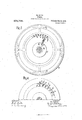
- Figure 1 is a vertical longitudinal section showing the turbine employed in a torpedo, Fig. 9 a section in the plane AB, and Fig. 3 a section through the shaft in the plane CD in Fig. 1;
- Fig. 4 is an elevation correspond ing to Fig. 2 showing a special construction of slide valve.
- the number of nozzles in each row is less than the number of blades in the rotor and the section of passage of all the nozzles is in addition, apart from the smaller number of nozzles, smaller than that in the rotor. Therefore, even when full admission takes place the turbine works only as a partial turbine.
- the face of the guide wheel turned from the rotor is provided with radially directed, slanting faces in which the nozzles are so inserted that they lie flush with these faces.
- the slanting faces at right angles to the direction of the nozzles form, in connection with the transmitting areas to the next nozzle, good guide faces for slid-e valves 0 movable .on the nozzle orifices and serving for closing the nozzle orifices of the guide wheel.
- All the slide valves 0 are guided radially at the guide wheel 9, the inner ends of their rods 1" engaging by means of pins r in slots 9 in a disk 29 revoluble around the pivot h, as shown in Fig. 2.
- the slide valves may be pressed on their seats in suitable manner,
- Disk 7 can be adjusted in suitable manner from the outside in order to close the nozzles 02, by means of the slide valves 0. The closure of the nozzles is then brought about always uniformly over the entire periphery, so that the rotor is impacted unifornily over its entire periphery.
- Shaft (Z of the turbine is made hollow and provided within casing a and behind rotor f with blades 11, below which the shaft has slots to, as clearly shown in Figs. 1 and 3.
- the turbine operates as follows:
- the pressure medium or motive fluid supplied through pipe 8 arrives in the distributing chamber t, whence it is supplied through the open nozzles 11, to rotor and drives the same.
- a plurality of guide wheels and rotors may be arranged in series in well-known manner.
- the medium impacting rotor f escapes into chamber a in casing a, whence it is driven by the blades 0 and guided to the outside through the slots Q0 and the hollow shaft (Z. hen the turbine is employed for torpedoes the repulsion of the emitting medium can be utilized in well-known manner for aiding the forward motion of the torpedo.
- nozzles n being closed by individual radially movable slide valves this may be done by one circular slide valve 8 common to all the nozzles as shown in Fig. a.
- This circular valve is provided with ports 3' recessed step-like, so that when the valve is moved by means of a pinion t and a toothed sector 8 the orifices of the nozzles of the individual concentric rows can be closed in succession;
- a turbine having a rotor provided with a row of buckets, a series of rows of nozzles opening to said row of buckets, each of the nozzles of each series having an independent controlled passage leading thereto, in combination with means for closing said pas sages serially in rows.
- a turbine having a rotor provided with a row of buckets, a series of rows of nozzles opening to said row of buckets, together with a circular rotary slide-valve common to all of said nozzles and perforated to form a stepped port whereby said nozzles may be controlled serially in rows.
- a turbine having a rotor provided with a row of buckets a series of rows of nozzles opening to said row of buckets and a rotary member adapted to effect the closure of said nozzles serially in rows.
- a hollow rotor shaft with ports opening into the same behind the rotor and blades on said shaft in proximity to said ports for forcing therethrough the motor fluid received from the rotor substantially as described.
Description
M. GLASS.
TURBINE.
APPLICATION TILED NOV. 22, 1909.
972,762, Patented Oct. 11, 1910.
8 SHEETS-SHEET 1.
M. GLASS.
TURBINE. APPLICATION rmm NOV. 2 2, 1909.
Patented Oct. 11, 1910.
amnsz,
'g aw MAX GLASS, 0]? VIENNA, AUSTRIA-HUNGARY.
TURBINE.
To all whom it may concern:
Be it known that I, MAX GLAss, a subject of the Emperor of Austria-Hungary, and a resident of 176 Hadikgasse, Vienna, Austria- Hungary, have invented certain new and useful Improvements in Turbines Driven by Compressed Media of Optional Kind; and I do hereby declare the following to be a full, clear, and exact description of the invention, such as will enable others skilled in the art to which it appertains to make and use the same, reference being had to the accompanying drawings, and to letters or figures of reference marked thereon, which form a part of this specification.
This invention relates to turbines driven by compressed media of optional kind.
In turbines which are always to run only with partial admission, as a rule a small number of nozzles or individual sets of nozzles are arranged distributed over the periphery. A consequence of this mode of construction, however is that only a portion of the moving blades is impacted simultaneously by the emitting jets of compressed medium or motive fluid, whereas the remaining blades run idle at the same moment. In turbines having nozzles distributed uniformly over the periphery and located comparatively close together, the nozzles are constructed in such manner that when they are entirely open full admission of the turbine is obtained. For running with partial admission the nozzles are then closed in order by means of slides, flaps or the like for example. When the nozzles are closed in such manner, however, the utilization of the motive fluid is too unfavorable in consequence of the non-uniform admission which is hereby brought about. Also, on account of the high speed of the rotor these turbines are not suitable for directly driving a shaft, but can only be used when a speeding down gear is interpolated.
Now a primary object of this invention is to form and arrange the guide wheel in such manner that the admission section of the nozzles and with it the speed of the rotor can be regulated within wide limits without the motive fluid being utilized unfavorably owing to throttling, and so that the turbine always works with partial admission even when all the nozzles are entirely open. To this end, the full section of passage of all the nozzles of the guide wheel arranged in one or more concentric rows and close to one Specification of Letters Patent.
Application filed November 22, 1909.
Patented Get. 11, 1910.
Serial No. 529,410.
another, is smaller than that of the rotor. The nozzles of the individual rows are arranged located on the same radius, so that when individual, simultaneously radially movable slide valves are employed or when a circular slide valve having ports recessed step-like is employed the nozzles are always closed in such manner that the admission is uniform over the entire periphery of the rotor at every degree of closure. As pressure medium or motive fluid for driving the turbine water, steam, compressed gas or compressed air may be used.
In the accompanying drawing: Figure 1 is a vertical longitudinal section showing the turbine employed in a torpedo, Fig. 9 a section in the plane AB, and Fig. 3 a section through the shaft in the plane CD in Fig. 1; Fig. 4: is an elevation correspond ing to Fig. 2 showing a special construction of slide valve.
Referring to the drawings, in a closed casing a attached to the torpedo body 6 by bracket 0 is journaled shaft 01 carrying rotor 7. In front of the rotor is inserted tightly in casing a the guide wheel g. This is guided centrically by means of a pivot 71, in the cover 2' and by means of a pivot 71; in a bolt m screwed into shaft (Z. In the guide wheel 5/ are arranged in a plurality of concentric rows the nozzles n for supplying the compressed medium 01' motive fluid to the rotor. The number of nozzles in each row is less than the number of blades in the rotor and the section of passage of all the nozzles is in addition, apart from the smaller number of nozzles, smaller than that in the rotor. Therefore, even when full admission takes place the turbine works only as a partial turbine. The face of the guide wheel turned from the rotor is provided with radially directed, slanting faces in which the nozzles are so inserted that they lie flush with these faces. The slanting faces at right angles to the direction of the nozzles form, in connection with the transmitting areas to the next nozzle, good guide faces for slid-e valves 0 movable .on the nozzle orifices and serving for closing the nozzle orifices of the guide wheel.
All the slide valves 0 are guided radially at the guide wheel 9, the inner ends of their rods 1" engaging by means of pins r in slots 9 in a disk 29 revoluble around the pivot h, as shown in Fig. 2. The slide valves may be pressed on their seats in suitable manner,
e; g. byineaiis of springs or by elastic rods 7*. Disk 7) can be adjusted in suitable manner from the outside in order to close the nozzles 02, by means of the slide valves 0. The closure of the nozzles is then brought about always uniformly over the entire periphery, so that the rotor is impacted unifornily over its entire periphery. Shaft (Z of the turbine is made hollow and provided within casing a and behind rotor f with blades 11, below which the shaft has slots to, as clearly shown in Figs. 1 and 3.
The turbine operates as follows: The pressure medium or motive fluid supplied through pipe 8 arrives in the distributing chamber t, whence it is supplied through the open nozzles 11, to rotor and drives the same. For the purpose of completely utilizing the tension of the motive fluid a plurality of guide wheels and rotors may be arranged in series in well-known manner. The medium impacting rotor f escapes into chamber a in casing a, whence it is driven by the blades 0 and guided to the outside through the slots Q0 and the hollow shaft (Z. hen the turbine is employed for torpedoes the repulsion of the emitting medium can be utilized in well-known manner for aiding the forward motion of the torpedo.
Instead of the nozzles n being closed by individual radially movable slide valves this may be done by one circular slide valve 8 common to all the nozzles as shown in Fig. a. This circular valve is provided with ports 3' recessed step-like, so that when the valve is moved by means of a pinion t and a toothed sector 8 the orifices of the nozzles of the individual concentric rows can be closed in succession;
I claim:
1. A turbine having a rotor provided with a row of buckets, a series of rows of nozzles opening to said row of buckets, each of the nozzles of each series having an independent controlled passage leading thereto, in combination with means for closing said pas sages serially in rows.
2. A turbine having a rotor provided with a row of buckets, a series of rows of nozzles opening to said row of buckets, together with a circular rotary slide-valve common to all of said nozzles and perforated to form a stepped port whereby said nozzles may be controlled serially in rows.
3. A turbine having a rotor provided with a row of buckets a series of rows of nozzles opening to said row of buckets and a rotary member adapted to effect the closure of said nozzles serially in rows.
4. In a turbine, a hollow rotor shaft with ports opening into the same behind the rotor and blades on said shaft in proximity to said ports for forcing therethrough the motor fluid received from the rotor substantially as described.
In testimony whereof I have signed my name to this specification in the presence of two subscribing witnesses.
MAX GLASS.
lVit-nesses RUDoLF ZIPsER, AUGUST FUGGER.
Priority Applications (1)
| Application Number | Priority Date | Filing Date | Title |
|---|---|---|---|
| US52941009A US972762A (en) | 1909-11-22 | 1909-11-22 | Turbine. |
Applications Claiming Priority (1)
| Application Number | Priority Date | Filing Date | Title |
|---|---|---|---|
| US52941009A US972762A (en) | 1909-11-22 | 1909-11-22 | Turbine. |
Publications (1)
| Publication Number | Publication Date |
|---|---|
| US972762A true US972762A (en) | 1910-10-11 |
Family
ID=3041142
Family Applications (1)
| Application Number | Title | Priority Date | Filing Date |
|---|---|---|---|
| US52941009A Expired - Lifetime US972762A (en) | 1909-11-22 | 1909-11-22 | Turbine. |
Country Status (1)
| Country | Link |
|---|---|
| US (1) | US972762A (en) |
Cited By (1)
| Publication number | Priority date | Publication date | Assignee | Title |
|---|---|---|---|---|
| US3761197A (en) * | 1972-02-18 | 1973-09-25 | D Kelly | Variable speed vapor turbine |
-
1909
- 1909-11-22 US US52941009A patent/US972762A/en not_active Expired - Lifetime
Cited By (1)
| Publication number | Priority date | Publication date | Assignee | Title |
|---|---|---|---|---|
| US3761197A (en) * | 1972-02-18 | 1973-09-25 | D Kelly | Variable speed vapor turbine |
Similar Documents
| Publication | Publication Date | Title |
|---|---|---|
| US972762A (en) | Turbine. | |
| US1110302A (en) | Rotary engine. | |
| US1402053A (en) | Elastic-fluid turbine | |
| US935046A (en) | Rotary engine. | |
| US861329A (en) | Explosion gas-turbine. | |
| US794606A (en) | Turbine. | |
| US714074A (en) | Steam-turbine. | |
| US1003321A (en) | Steam-turbine. | |
| US584580A (en) | Vidson | |
| US788005A (en) | Controller mechanism for turbines. | |
| US584578A (en) | davidson | |
| US1473690A (en) | Serial-flow turbine | |
| US525693A (en) | Valve-gear | |
| US571861A (en) | Steam-turbine | |
| US796395A (en) | Elastic-fluid motor. | |
| US829992A (en) | Turbine. | |
| US649859A (en) | Turbine motor. | |
| US706372A (en) | Rotary engine. | |
| US929512A (en) | Rotary engine. | |
| US751587A (en) | Rotary fluid-motor | |
| US883910A (en) | Reversible turbine-engine. | |
| US808709A (en) | Turbine-engine. | |
| US1030278A (en) | Steam-turbine. | |
| US794898A (en) | Steam or gas turbine. | |
| US767189A (en) | Steam-turbine. |