US9702288B2 - Emissions cleaning module - Google Patents
Emissions cleaning module Download PDFInfo
- Publication number
- US9702288B2 US9702288B2 US14/391,599 US201214391599A US9702288B2 US 9702288 B2 US9702288 B2 US 9702288B2 US 201214391599 A US201214391599 A US 201214391599A US 9702288 B2 US9702288 B2 US 9702288B2
- Authority
- US
- United States
- Prior art keywords
- support
- module
- inner body
- outer body
- cleaning module
- Prior art date
- Legal status (The legal status is an assumption and is not a legal conclusion. Google has not performed a legal analysis and makes no representation as to the accuracy of the status listed.)
- Active
Links
Images


Classifications
-
- F—MECHANICAL ENGINEERING; LIGHTING; HEATING; WEAPONS; BLASTING
- F01—MACHINES OR ENGINES IN GENERAL; ENGINE PLANTS IN GENERAL; STEAM ENGINES
- F01N—GAS-FLOW SILENCERS OR EXHAUST APPARATUS FOR MACHINES OR ENGINES IN GENERAL; GAS-FLOW SILENCERS OR EXHAUST APPARATUS FOR INTERNAL-COMBUSTION ENGINES
- F01N3/00—Exhaust or silencing apparatus having means for purifying, rendering innocuous, or otherwise treating exhaust
- F01N3/08—Exhaust or silencing apparatus having means for purifying, rendering innocuous, or otherwise treating exhaust for rendering innocuous
- F01N3/10—Exhaust or silencing apparatus having means for purifying, rendering innocuous, or otherwise treating exhaust for rendering innocuous by thermal or catalytic conversion of noxious components of exhaust
- F01N3/18—Exhaust or silencing apparatus having means for purifying, rendering innocuous, or otherwise treating exhaust for rendering innocuous by thermal or catalytic conversion of noxious components of exhaust characterised by methods of operation; Control
- F01N3/20—Exhaust or silencing apparatus having means for purifying, rendering innocuous, or otherwise treating exhaust for rendering innocuous by thermal or catalytic conversion of noxious components of exhaust characterised by methods of operation; Control specially adapted for catalytic conversion
-
- B—PERFORMING OPERATIONS; TRANSPORTING
- B01—PHYSICAL OR CHEMICAL PROCESSES OR APPARATUS IN GENERAL
- B01D—SEPARATION
- B01D46/00—Filters or filtering processes specially modified for separating dispersed particles from gases or vapours
- B01D46/0002—Casings; Housings; Frame constructions
-
- B01D46/0057—
-
- B—PERFORMING OPERATIONS; TRANSPORTING
- B01—PHYSICAL OR CHEMICAL PROCESSES OR APPARATUS IN GENERAL
- B01D—SEPARATION
- B01D46/00—Filters or filtering processes specially modified for separating dispersed particles from gases or vapours
- B01D46/66—Regeneration of the filtering material or filter elements inside the filter
-
- B—PERFORMING OPERATIONS; TRANSPORTING
- B01—PHYSICAL OR CHEMICAL PROCESSES OR APPARATUS IN GENERAL
- B01D—SEPARATION
- B01D53/00—Separation of gases or vapours; Recovering vapours of volatile solvents from gases; Chemical or biological purification of waste gases, e.g. engine exhaust gases, smoke, fumes, flue gases, aerosols
- B01D53/34—Chemical or biological purification of waste gases
- B01D53/74—General processes for purification of waste gases; Apparatus or devices specially adapted therefor
- B01D53/86—Catalytic processes
- B01D53/864—Removing carbon monoxide or hydrocarbons
-
- B—PERFORMING OPERATIONS; TRANSPORTING
- B01—PHYSICAL OR CHEMICAL PROCESSES OR APPARATUS IN GENERAL
- B01D—SEPARATION
- B01D53/00—Separation of gases or vapours; Recovering vapours of volatile solvents from gases; Chemical or biological purification of waste gases, e.g. engine exhaust gases, smoke, fumes, flue gases, aerosols
- B01D53/34—Chemical or biological purification of waste gases
- B01D53/92—Chemical or biological purification of waste gases of engine exhaust gases
-
- B—PERFORMING OPERATIONS; TRANSPORTING
- B60—VEHICLES IN GENERAL
- B60R—VEHICLES, VEHICLE FITTINGS, OR VEHICLE PARTS, NOT OTHERWISE PROVIDED FOR
- B60R13/00—Elements for body-finishing, identifying, or decorating; Arrangements or adaptations for advertising purposes
- B60R13/08—Insulating elements, e.g. for sound insulation
- B60R13/0876—Insulating elements, e.g. for sound insulation for mounting around heat sources, e.g. exhaust pipes
-
- F—MECHANICAL ENGINEERING; LIGHTING; HEATING; WEAPONS; BLASTING
- F01—MACHINES OR ENGINES IN GENERAL; ENGINE PLANTS IN GENERAL; STEAM ENGINES
- F01N—GAS-FLOW SILENCERS OR EXHAUST APPARATUS FOR MACHINES OR ENGINES IN GENERAL; GAS-FLOW SILENCERS OR EXHAUST APPARATUS FOR INTERNAL-COMBUSTION ENGINES
- F01N13/00—Exhaust or silencing apparatus characterised by constructional features
- F01N13/008—Mounting or arrangement of exhaust sensors in or on exhaust apparatus
-
- F—MECHANICAL ENGINEERING; LIGHTING; HEATING; WEAPONS; BLASTING
- F01—MACHINES OR ENGINES IN GENERAL; ENGINE PLANTS IN GENERAL; STEAM ENGINES
- F01N—GAS-FLOW SILENCERS OR EXHAUST APPARATUS FOR MACHINES OR ENGINES IN GENERAL; GAS-FLOW SILENCERS OR EXHAUST APPARATUS FOR INTERNAL-COMBUSTION ENGINES
- F01N13/00—Exhaust or silencing apparatus characterised by constructional features
- F01N13/08—Other arrangements or adaptations of exhaust conduits
-
- F—MECHANICAL ENGINEERING; LIGHTING; HEATING; WEAPONS; BLASTING
- F01—MACHINES OR ENGINES IN GENERAL; ENGINE PLANTS IN GENERAL; STEAM ENGINES
- F01N—GAS-FLOW SILENCERS OR EXHAUST APPARATUS FOR MACHINES OR ENGINES IN GENERAL; GAS-FLOW SILENCERS OR EXHAUST APPARATUS FOR INTERNAL-COMBUSTION ENGINES
- F01N13/00—Exhaust or silencing apparatus characterised by constructional features
- F01N13/14—Exhaust or silencing apparatus characterised by constructional features having thermal insulation
- F01N13/141—Double-walled exhaust pipes or housings
- F01N13/143—Double-walled exhaust pipes or housings with air filling the space between both walls
-
- F—MECHANICAL ENGINEERING; LIGHTING; HEATING; WEAPONS; BLASTING
- F01—MACHINES OR ENGINES IN GENERAL; ENGINE PLANTS IN GENERAL; STEAM ENGINES
- F01N—GAS-FLOW SILENCERS OR EXHAUST APPARATUS FOR MACHINES OR ENGINES IN GENERAL; GAS-FLOW SILENCERS OR EXHAUST APPARATUS FOR INTERNAL-COMBUSTION ENGINES
- F01N13/00—Exhaust or silencing apparatus characterised by constructional features
- F01N13/18—Construction facilitating manufacture, assembly, or disassembly
- F01N13/1805—Fixing exhaust manifolds, exhaust pipes or pipe sections to each other, to engine or to vehicle body
-
- F—MECHANICAL ENGINEERING; LIGHTING; HEATING; WEAPONS; BLASTING
- F01—MACHINES OR ENGINES IN GENERAL; ENGINE PLANTS IN GENERAL; STEAM ENGINES
- F01N—GAS-FLOW SILENCERS OR EXHAUST APPARATUS FOR MACHINES OR ENGINES IN GENERAL; GAS-FLOW SILENCERS OR EXHAUST APPARATUS FOR INTERNAL-COMBUSTION ENGINES
- F01N3/00—Exhaust or silencing apparatus having means for purifying, rendering innocuous, or otherwise treating exhaust
- F01N3/02—Exhaust or silencing apparatus having means for purifying, rendering innocuous, or otherwise treating exhaust for cooling, or for removing solid constituents of, exhaust
- F01N3/021—Exhaust or silencing apparatus having means for purifying, rendering innocuous, or otherwise treating exhaust for cooling, or for removing solid constituents of, exhaust by means of filters
- F01N3/023—Exhaust or silencing apparatus having means for purifying, rendering innocuous, or otherwise treating exhaust for cooling, or for removing solid constituents of, exhaust by means of filters using means for regenerating the filters, e.g. by burning trapped particles
- F01N3/0233—Exhaust or silencing apparatus having means for purifying, rendering innocuous, or otherwise treating exhaust for cooling, or for removing solid constituents of, exhaust by means of filters using means for regenerating the filters, e.g. by burning trapped particles periodically cleaning filter by blowing a gas through the filter in a direction opposite to exhaust flow, e.g. exposing filter to engine air intake
-
- F—MECHANICAL ENGINEERING; LIGHTING; HEATING; WEAPONS; BLASTING
- F01—MACHINES OR ENGINES IN GENERAL; ENGINE PLANTS IN GENERAL; STEAM ENGINES
- F01N—GAS-FLOW SILENCERS OR EXHAUST APPARATUS FOR MACHINES OR ENGINES IN GENERAL; GAS-FLOW SILENCERS OR EXHAUST APPARATUS FOR INTERNAL-COMBUSTION ENGINES
- F01N3/00—Exhaust or silencing apparatus having means for purifying, rendering innocuous, or otherwise treating exhaust
- F01N3/02—Exhaust or silencing apparatus having means for purifying, rendering innocuous, or otherwise treating exhaust for cooling, or for removing solid constituents of, exhaust
- F01N3/021—Exhaust or silencing apparatus having means for purifying, rendering innocuous, or otherwise treating exhaust for cooling, or for removing solid constituents of, exhaust by means of filters
- F01N3/033—Exhaust or silencing apparatus having means for purifying, rendering innocuous, or otherwise treating exhaust for cooling, or for removing solid constituents of, exhaust by means of filters in combination with other devices
- F01N3/035—Exhaust or silencing apparatus having means for purifying, rendering innocuous, or otherwise treating exhaust for cooling, or for removing solid constituents of, exhaust by means of filters in combination with other devices with catalytic reactors
-
- F—MECHANICAL ENGINEERING; LIGHTING; HEATING; WEAPONS; BLASTING
- F01—MACHINES OR ENGINES IN GENERAL; ENGINE PLANTS IN GENERAL; STEAM ENGINES
- F01N—GAS-FLOW SILENCERS OR EXHAUST APPARATUS FOR MACHINES OR ENGINES IN GENERAL; GAS-FLOW SILENCERS OR EXHAUST APPARATUS FOR INTERNAL-COMBUSTION ENGINES
- F01N3/00—Exhaust or silencing apparatus having means for purifying, rendering innocuous, or otherwise treating exhaust
- F01N3/08—Exhaust or silencing apparatus having means for purifying, rendering innocuous, or otherwise treating exhaust for rendering innocuous
- F01N3/10—Exhaust or silencing apparatus having means for purifying, rendering innocuous, or otherwise treating exhaust for rendering innocuous by thermal or catalytic conversion of noxious components of exhaust
- F01N3/24—Exhaust or silencing apparatus having means for purifying, rendering innocuous, or otherwise treating exhaust for rendering innocuous by thermal or catalytic conversion of noxious components of exhaust characterised by constructional aspects of converting apparatus
- F01N3/28—Construction of catalytic reactors
- F01N3/2892—Exhaust flow directors or the like, e.g. upstream of catalytic device
-
- F—MECHANICAL ENGINEERING; LIGHTING; HEATING; WEAPONS; BLASTING
- F01—MACHINES OR ENGINES IN GENERAL; ENGINE PLANTS IN GENERAL; STEAM ENGINES
- F01N—GAS-FLOW SILENCERS OR EXHAUST APPARATUS FOR MACHINES OR ENGINES IN GENERAL; GAS-FLOW SILENCERS OR EXHAUST APPARATUS FOR INTERNAL-COMBUSTION ENGINES
- F01N9/00—Electrical control of exhaust gas treating apparatus
-
- G—PHYSICS
- G01—MEASURING; TESTING
- G01M—TESTING STATIC OR DYNAMIC BALANCE OF MACHINES OR STRUCTURES; TESTING OF STRUCTURES OR APPARATUS, NOT OTHERWISE PROVIDED FOR
- G01M15/00—Testing of engines
- G01M15/04—Testing internal-combustion engines
- G01M15/10—Testing internal-combustion engines by monitoring exhaust gases or combustion flame
- G01M15/102—Testing internal-combustion engines by monitoring exhaust gases or combustion flame by monitoring exhaust gases
-
- H—ELECTRICITY
- H05—ELECTRIC TECHNIQUES NOT OTHERWISE PROVIDED FOR
- H05K—PRINTED CIRCUITS; CASINGS OR CONSTRUCTIONAL DETAILS OF ELECTRIC APPARATUS; MANUFACTURE OF ASSEMBLAGES OF ELECTRICAL COMPONENTS
- H05K5/00—Casings, cabinets or drawers for electric apparatus
- H05K5/02—Details
-
- H—ELECTRICITY
- H05—ELECTRIC TECHNIQUES NOT OTHERWISE PROVIDED FOR
- H05K—PRINTED CIRCUITS; CASINGS OR CONSTRUCTIONAL DETAILS OF ELECTRIC APPARATUS; MANUFACTURE OF ASSEMBLAGES OF ELECTRICAL COMPONENTS
- H05K7/00—Constructional details common to different types of electric apparatus
- H05K7/20—Modifications to facilitate cooling, ventilating, or heating
- H05K7/2039—Modifications to facilitate cooling, ventilating, or heating characterised by the heat transfer by conduction from the heat generating element to a dissipating body
- H05K7/20436—Inner thermal coupling elements in heat dissipating housings, e.g. protrusions or depressions integrally formed in the housing
-
- B01F2005/0621—
-
- B01F2005/0636—
-
- B—PERFORMING OPERATIONS; TRANSPORTING
- B01—PHYSICAL OR CHEMICAL PROCESSES OR APPARATUS IN GENERAL
- B01F—MIXING, e.g. DISSOLVING, EMULSIFYING OR DISPERSING
- B01F25/00—Flow mixers; Mixers for falling materials, e.g. solid particles
- B01F25/40—Static mixers
- B01F25/42—Static mixers in which the mixing is affected by moving the components jointly in changing directions, e.g. in tubes provided with baffles or obstructions
- B01F25/43—Mixing tubes, e.g. wherein the material is moved in a radial or partly reversed direction
- B01F25/431—Straight mixing tubes with baffles or obstructions that do not cause substantial pressure drop; Baffles therefor
- B01F25/4313—Straight mixing tubes with baffles or obstructions that do not cause substantial pressure drop; Baffles therefor comprising a plurality of stacked ducts having their axes parallel to the tube axis
-
- B—PERFORMING OPERATIONS; TRANSPORTING
- B01—PHYSICAL OR CHEMICAL PROCESSES OR APPARATUS IN GENERAL
- B01F—MIXING, e.g. DISSOLVING, EMULSIFYING OR DISPERSING
- B01F25/00—Flow mixers; Mixers for falling materials, e.g. solid particles
- B01F25/40—Static mixers
- B01F25/42—Static mixers in which the mixing is affected by moving the components jointly in changing directions, e.g. in tubes provided with baffles or obstructions
- B01F25/43—Mixing tubes, e.g. wherein the material is moved in a radial or partly reversed direction
- B01F25/431—Straight mixing tubes with baffles or obstructions that do not cause substantial pressure drop; Baffles therefor
- B01F25/4317—Profiled elements, e.g. profiled blades, bars, pillars, columns or chevrons
-
- B—PERFORMING OPERATIONS; TRANSPORTING
- B01—PHYSICAL OR CHEMICAL PROCESSES OR APPARATUS IN GENERAL
- B01F—MIXING, e.g. DISSOLVING, EMULSIFYING OR DISPERSING
- B01F25/00—Flow mixers; Mixers for falling materials, e.g. solid particles
- B01F25/40—Static mixers
- B01F25/42—Static mixers in which the mixing is affected by moving the components jointly in changing directions, e.g. in tubes provided with baffles or obstructions
- B01F25/43—Mixing tubes, e.g. wherein the material is moved in a radial or partly reversed direction
- B01F25/431—Straight mixing tubes with baffles or obstructions that do not cause substantial pressure drop; Baffles therefor
- B01F25/43197—Straight mixing tubes with baffles or obstructions that do not cause substantial pressure drop; Baffles therefor characterised by the mounting of the baffles or obstructions
- B01F25/431971—Mounted on the wall
-
- B01F5/0613—
-
- F—MECHANICAL ENGINEERING; LIGHTING; HEATING; WEAPONS; BLASTING
- F01—MACHINES OR ENGINES IN GENERAL; ENGINE PLANTS IN GENERAL; STEAM ENGINES
- F01N—GAS-FLOW SILENCERS OR EXHAUST APPARATUS FOR MACHINES OR ENGINES IN GENERAL; GAS-FLOW SILENCERS OR EXHAUST APPARATUS FOR INTERNAL-COMBUSTION ENGINES
- F01N1/00—Silencing apparatus characterised by method of silencing
- F01N1/08—Silencing apparatus characterised by method of silencing by reducing exhaust energy by throttling or whirling
- F01N1/086—Silencing apparatus characterised by method of silencing by reducing exhaust energy by throttling or whirling having means to impart a whirling motion to the exhaust gases
-
- F—MECHANICAL ENGINEERING; LIGHTING; HEATING; WEAPONS; BLASTING
- F01—MACHINES OR ENGINES IN GENERAL; ENGINE PLANTS IN GENERAL; STEAM ENGINES
- F01N—GAS-FLOW SILENCERS OR EXHAUST APPARATUS FOR MACHINES OR ENGINES IN GENERAL; GAS-FLOW SILENCERS OR EXHAUST APPARATUS FOR INTERNAL-COMBUSTION ENGINES
- F01N2240/00—Combination or association of two or more different exhaust treating devices, or of at least one such device with an auxiliary device, not covered by indexing codes F01N2230/00 or F01N2250/00, one of the devices being
- F01N2240/20—Combination or association of two or more different exhaust treating devices, or of at least one such device with an auxiliary device, not covered by indexing codes F01N2230/00 or F01N2250/00, one of the devices being a flow director or deflector
-
- F—MECHANICAL ENGINEERING; LIGHTING; HEATING; WEAPONS; BLASTING
- F01—MACHINES OR ENGINES IN GENERAL; ENGINE PLANTS IN GENERAL; STEAM ENGINES
- F01N—GAS-FLOW SILENCERS OR EXHAUST APPARATUS FOR MACHINES OR ENGINES IN GENERAL; GAS-FLOW SILENCERS OR EXHAUST APPARATUS FOR INTERNAL-COMBUSTION ENGINES
- F01N2260/00—Exhaust treating devices having provisions not otherwise provided for
- F01N2260/02—Exhaust treating devices having provisions not otherwise provided for for cooling the device
- F01N2260/022—Exhaust treating devices having provisions not otherwise provided for for cooling the device using air
-
- F—MECHANICAL ENGINEERING; LIGHTING; HEATING; WEAPONS; BLASTING
- F01—MACHINES OR ENGINES IN GENERAL; ENGINE PLANTS IN GENERAL; STEAM ENGINES
- F01N—GAS-FLOW SILENCERS OR EXHAUST APPARATUS FOR MACHINES OR ENGINES IN GENERAL; GAS-FLOW SILENCERS OR EXHAUST APPARATUS FOR INTERNAL-COMBUSTION ENGINES
- F01N2260/00—Exhaust treating devices having provisions not otherwise provided for
- F01N2260/20—Exhaust treating devices having provisions not otherwise provided for for heat or sound protection, e.g. using a shield or specially shaped outer surface of exhaust device
-
- F—MECHANICAL ENGINEERING; LIGHTING; HEATING; WEAPONS; BLASTING
- F01—MACHINES OR ENGINES IN GENERAL; ENGINE PLANTS IN GENERAL; STEAM ENGINES
- F01N—GAS-FLOW SILENCERS OR EXHAUST APPARATUS FOR MACHINES OR ENGINES IN GENERAL; GAS-FLOW SILENCERS OR EXHAUST APPARATUS FOR INTERNAL-COMBUSTION ENGINES
- F01N2450/00—Methods or apparatus for fitting, inserting or repairing different elements
- F01N2450/22—Methods or apparatus for fitting, inserting or repairing different elements by welding or brazing
-
- F—MECHANICAL ENGINEERING; LIGHTING; HEATING; WEAPONS; BLASTING
- F01—MACHINES OR ENGINES IN GENERAL; ENGINE PLANTS IN GENERAL; STEAM ENGINES
- F01N—GAS-FLOW SILENCERS OR EXHAUST APPARATUS FOR MACHINES OR ENGINES IN GENERAL; GAS-FLOW SILENCERS OR EXHAUST APPARATUS FOR INTERNAL-COMBUSTION ENGINES
- F01N2470/00—Structure or shape of exhaust gas passages, pipes or tubes
- F01N2470/02—Tubes being perforated
- F01N2470/04—Tubes being perforated characterised by shape, disposition or dimensions of apertures
-
- F—MECHANICAL ENGINEERING; LIGHTING; HEATING; WEAPONS; BLASTING
- F01—MACHINES OR ENGINES IN GENERAL; ENGINE PLANTS IN GENERAL; STEAM ENGINES
- F01N—GAS-FLOW SILENCERS OR EXHAUST APPARATUS FOR MACHINES OR ENGINES IN GENERAL; GAS-FLOW SILENCERS OR EXHAUST APPARATUS FOR INTERNAL-COMBUSTION ENGINES
- F01N2490/00—Structure, disposition or shape of gas-chambers
- F01N2490/02—Two or more expansion chambers in series connected by means of tubes
- F01N2490/06—Two or more expansion chambers in series connected by means of tubes the gases flowing longitudinally from inlet to outlet in opposite directions
-
- F—MECHANICAL ENGINEERING; LIGHTING; HEATING; WEAPONS; BLASTING
- F01—MACHINES OR ENGINES IN GENERAL; ENGINE PLANTS IN GENERAL; STEAM ENGINES
- F01N—GAS-FLOW SILENCERS OR EXHAUST APPARATUS FOR MACHINES OR ENGINES IN GENERAL; GAS-FLOW SILENCERS OR EXHAUST APPARATUS FOR INTERNAL-COMBUSTION ENGINES
- F01N2610/00—Adding substances to exhaust gases
- F01N2610/14—Arrangements for the supply of substances, e.g. conduits
- F01N2610/1453—Sprayers or atomisers; Arrangement thereof in the exhaust apparatus
-
- Y—GENERAL TAGGING OF NEW TECHNOLOGICAL DEVELOPMENTS; GENERAL TAGGING OF CROSS-SECTIONAL TECHNOLOGIES SPANNING OVER SEVERAL SECTIONS OF THE IPC; TECHNICAL SUBJECTS COVERED BY FORMER USPC CROSS-REFERENCE ART COLLECTIONS [XRACs] AND DIGESTS
- Y10—TECHNICAL SUBJECTS COVERED BY FORMER USPC
- Y10T—TECHNICAL SUBJECTS COVERED BY FORMER US CLASSIFICATION
- Y10T29/00—Metal working
- Y10T29/49—Method of mechanical manufacture
- Y10T29/49345—Catalytic device making
Definitions
- the disclosure relates to an apparatus for cleaning fluids emitted during the operation of combustion engines.
- Engines for example IC engines burning gasoline, diesel or biofuel, output various harmful substances which must be treated to meet current and future emissions legislation. Most commonly those substances comprise hydrocarbons (HC), carbon monoxides (CO), mono-nitrogen oxides (NO x ) and particulate matter, such as carbon (C), a constituent of soot. Some of those substances may be reduced by careful control of the operating conditions of the engine, but usually it is necessary to provide an emissions cleaning module downstream of the engine to treat at least some of those substances entrained in the exhaust gas.
- Various apparatus for reducing and/or eliminating constituents in emissions are known.
- Oxidation devices such as a diesel oxidation catalyst, to reduce or to eliminate hydrocarbons (HC) and/or carbon monoxide (CO).
- Oxidation devices generally include a catalyst to convert those substances into carbon dioxide and water, which are significantly less harmful.
- emissions cleaning modules may include a particulate filter to restrict the particulates present in the exhaust gas from being output to atmosphere.
- engine emissions can be cleaned, meaning that a proportion of the harmful substances which would otherwise be released to atmosphere are instead converted to carbon dioxide (CO 2 ), nitrogen (N 2 ) and water (H 2 O).
- CO 2 carbon dioxide
- N 2 nitrogen
- H 2 O water
- engine emissions can be cleaned, meaning that a proportion of the harmful substances which would otherwise be released to atmosphere are instead converted to carbon dioxide (CO 2 ), nitrogen (N 2 ) and water (H 2 O).
- CO 2 carbon dioxide
- N 2 nitrogen
- H 2 O water
- Emissions cleaning modules may also comprise an injector module for injecting a fluid, such as urea, into the engine emissions flow. It is also know to include a mixer module to aid mixer of the injected urea with the engine emissions flow.
- US2010/0257850 describes an emission cleaning module having a mixer pipe.
- the mixer pipe is comprised of inner and outer pipes which are overlapped with each other in a relatively stretchable and retractable manner.
- the inner pipe is fixed at a right-hand end to a housing and the outer pipe is secured to an outer periphery of the inner pipe part-way along its length.
- a sliding seal is provided at an opposite end of the inner pipe.
- the structure of the mixer module of US2010/0257850 is relatively complicated.
- an emissions cleaning module comprising an improved arrangement of mixer module.
- an emissions cleaning module comprising:
- FIG. 1 shows an emissions cleaning module in accordance with the present disclosure
- FIG. 2 shows a support frame of the emissions cleaning module of FIG. 1 ;
- FIG. 3 shows a partial cross-section of the emissions cleaning module of FIG. 1 ;
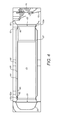
- FIG. 4 shows a cross section of a mixer module of the emissions cleaning module of FIG. 1 .
- An emissions cleaning module 1 is illustrated in FIG. 1 .
- the emissions cleaning module 1 may comprise a first conduit 10 and a second conduit 20 .
- a third conduit 30 and a support structure 40 may also be present.
- the support structure 40 comprises a first support member 50 and a second support member 60 .
- Each support member 50 , 60 may be generally planar and may be of rigid material, for example metal.
- the first, second and third conduits 10 , 20 , 30 may be elongate, having an axis of elongation, and may have substantially constant cross-section along the axis of elongation.
- the first, second and third conduits 10 , 20 , 30 may be substantially cylindrical.
- the first conduit 10 comprises a first end 11 providing an inlet to the conduit and a second end 12 providing an outlet to the conduit.
- the second conduit 20 comprises a first end 21 providing an outlet to the conduit and a second end 22 providing an inlet to the conduit.
- the third conduit 30 may comprise a first end 31 providing an inlet to the conduit and a second end providing an outlet to the conduit.
- the conduits 10 , 20 , 30 may extend between the support members 50 , 60 .
- the conduits 10 , 20 , 30 may be generally substantially parallel.
- the first ends 11 , 21 , 31 of the first, second and third conduits 10 , 20 , 30 may be received in and may be shaped to correspond with first, second and third openings 51 , 52 , 53 , respectively, of the first support member 50 .
- the second ends 12 , 22 of the first, second and third conduits 10 , 20 , 30 may be received in and may be shaped to correspond with first, second and third openings 61 , 62 , 63 , respectively, of the second support member 60 .
- lateral movement of the conduits may be restricted.
- each opening 51 , 52 , 53 , 61 , 62 , 63 may comprise a flange 51 a , 52 a , 53 a , 61 a , 62 a , 63 a extending around a perimeter of the opening.
- Each support member 50 , 60 may further comprise an inwardly turned lip 59 , 69 extending at least part way around a periphery of the support member 50 , 60 .
- the conduits 10 , 20 , 30 may all be of substantially similar length.
- the first conduit 10 may have a first diameter
- the second conduit 20 may have a second diameter
- the third conduit 30 may have a third diameter.
- the second diameter may be smaller than the first and third diameters.
- first and second ends 11 , 21 , 31 , 12 , 22 of the conduits 10 , 20 , 30 may be welded, adhered or otherwise secured to portions of the support members 50 , 60 defining or surrounding the openings.
- first and second ends 11 , 21 , 31 , 12 , 22 of the conduits 10 , 20 , 30 may abut the inner sides of the support members 50 , 60 so as to overlie respective openings in the support members 50 , 60 .
- the first, second and third conduits 10 , 20 , 30 and the first and second support members 50 , 60 may be interconnected in a manner which restricts relative translational movement of those components.
- the first, second and third conduits 10 , 20 , 30 and the first and second support members 50 , 60 may be interconnected in a manner which restricts rotational movement of one component with respect to another.
- the first conduit 10 is fluidly coupled to the second conduit 20 via a first end coupling 15 which fluidly connects the outlet of the first conduit 10 to the inlet of the second conduit 20 .
- the first end coupling 15 may comprise an injector module 16 .
- the second conduit 20 may be coupled to the third conduit 30 via a second end coupling 25 for fluidly connecting the outlet of the second conduit 20 to the inlet of the third conduit 30 .
- Each of the first and second end couplings may define, in combination with its respective support member, a fluid flow path through which exhaust gas may pass between adjacent conduits.
- DOC diesel oxidation catalyst
- DPF diesel particulate filter
- injector module 16 an injector module 16
- mixer module 75 a selective catalyst reduction (SCR) module and an ammonia oxidation catalyst (AMOX) module.
- SCR selective catalyst reduction
- AMOX ammonia oxidation catalyst
- the DOC module 71 may be located in a first portion of the first conduit 10 towards the first, inlet, end 11 of the first conduit 10 .
- the DPF module 70 may be located in a second portion of the first conduit 10 towards the second, outlet, end 12 of the first conduit 10 .
- the first end coupling 15 may provide a fluid flow path from the second end 12 of the first conduit 10 to the second end 22 of the second conduit 20 .
- the first end coupling 15 may comprise the injector module 16 .
- the mixer module 75 may be located in, or formed by, the second conduit 20 .
- the mixer module 75 may be configured to mix a fluid injected by the injector module 16 with a fluid arriving from the first conduit 10 .
- the mixer module 75 may comprise multiple features, such as interspersed fins, which may give rise to an even blend of the injected fluid with the fluid from the first conduit 10 .
- the second end coupling 25 may provide a fluid flow path from the first end 21 of the second conduit to the first end 31 of the third conduit 30 .
- the mixer module 75 comprises an outer body 80 and an inner body 81 located within the outer body 80 .
- the outer body 80 may form the external skin of the second conduit 20 .
- An air gap 88 may be provided between the inner body 81 and the outer body 80 .
- the outer body 80 may be elongate and extends between the first support 50 and the second support 60 .
- the outer body 80 may be cylindrical and may have a constant diameter except at the ends therefore which may have a smaller diameter.
- a first end 82 of the outer body 80 is fixedly retained to the first support 50 .
- the fixation may be by means of a weld between the first end 82 and the flange 52 a .
- the connection may be to an inner or outer face of the flange 52 a .
- a second end 83 of the outer body 80 is fixedly retained to the second support 60 .
- the fixation may be by means of a weld between the second end 83 and the flange 62 a .
- the connection may be to an inner or outer face of the flange 62 a.
- the inner body 81 may be elongate.
- the inner body 81 may be cylindrical and may have a constant diameter. Alternatively, as shown, it may have a tapered section 87 leading to one end having a smaller diameter than another.
- a first end 85 of the inner body 81 is slidingly retained within the outer body 82 .
- the first end 85 of the inner body 81 may be slidingly retained in contact with the first end 82 of the outer body 80 .
- the first end 85 of the inner body 81 may form a slidable interference fit within the first end 82 of the outer body 80 .
- a second end 86 of the inner body 81 is fixedly retained relative to the outer body 80 at or near the second support 60 .
- the fixation may be by means of a weld between the second end 86 and the outer body 80 .
- the fixation may be by means of a weld between the second end 86 and the second support 60 .
- a single weld is used to join the second end 86 of the inner body 81 , the second end 83 of the outer body 80 and the second support 60 .
- outer body 80 and second support 60 may be prevented from moving axially relative to one another.
- the inner body 81 is free to move axially relative to the outer body 80 .
- the SCR module may be located in a first portion of the third conduit 30 towards the first end 31 of the third conduit 30 .
- the SCR module may comprise a catalyst surface intended to catalyse a reaction to occur between the two fluids mixed in the mixer module and output by the diffuser.
- the AMOX module may both be located in a second portion of the third conduit 30 towards the second end of the third conduit 30 .
- the AMOX module may comprise a catalyst which may catalyse a reaction of one or more of the products output from the SCR module.
- fluid may be supplied to the emissions cleaning module 1 via an inlet 4 . Fluid may pass into the DOC module 71 in the first portion of the first conduit 10 . Prior to receipt at the inlet 4 , the pressure of the fluid may be controlled by a back pressure valve.
- the DOC module 71 may comprise one or more catalysts, such as palladium or platinum. These materials serve as catalysts to cause oxidation of hydrocarbons ([HC]) and carbon monoxide (CO) present in the fluid flow in order to produce carbon dioxide (CO 2 ) and water (H 2 O).
- the catalysts may be distributed in a manner so as to maximise the surface area of catalyst material in order to increase effectiveness of the catalyst in catalysing reactions.
- Fluid may flow from the DOC module 71 to the DPF module 70 which comprises features which are intended to prevent onward passage of carbon (C) in the form of soot. Carbon particles in the fluid may thus trapped in the filter.
- the filter may be regenerated through known regeneration techniques. These techniques may involve controlling one or more of the temperature of the fluid, the pressure of the fluid and the proportion of unburnt fuel in the fluid.
- the injector module 16 may be associated with or attachable to a pump electronic tank unit (PETU).
- PETU pump electronic tank unit
- the pump electronic tank unit may comprise a tank for providing a reservoir for fluid to be injected by the injector. Such fluids may include urea or ammonia.
- the tank may comprise a lower portion having a first cross sectional area and an upper portion having a second cross sectional area.
- the second cross sectional area may be smaller than the first cross sectional area.
- the difference in cross sectional area between the first and second portions may provide for a volume to house additional components of the PETU. This may provide better protection than if components were simply attached to an otherwise external surface of the tank.
- the PETU may further comprise a controller configured to control a volume of fluid to be injected from the tank by the injector.
- the controller may have as inputs, for example, temperature information and quantity of NO x information which may be derived from sensors in the SCR module.
- Fluid may pass from the injector module 16 into the mixer module 75 located in the second conduit 20 .
- the mixer module 75 may comprise features for ensuring that the fluid originating from the first conduit 10 is well mixed with the fluid originating from the injector 16 . Fluids flowing into the mixer module 75 may be hot causing thermal expansion of the inner body 81 of the second conduit 20 . Any such expansion may be accommodated by relative sliding movement between the first end 85 of the inner body 81 and the first end 82 of the outer body 80 . The relative movement may be constrained to be only or mainly a relative axial movement. The overlap between the inner body 81 and the outer body 80 at the first end 21 of the second conduit 20 may be sufficiently great to prevent opening of the air gap 88 during any expansion or contraction of the inner body 81 .
- the SCR module may comprise one or more catalysts through which the mixture of exhaust gas and urea/ammonia may flow. As the mixture passes over the surfaces of the catalyst a may reaction occur which converts the ammonia and NO x to diatomic nitrogen (N 2 ) and water (H 2 O).
- Fluid may pass from the SCR module to the AMOX module located in the second portion of the third conduit 30 .
- the AMOX module may comprise an oxidation catalyst which may cause residual ammonia present in the fluid exiting the SCR module to react to produce nitrogen (N 2 ) and water (H 2 O).
- Fluid may pass from the AMOX module to the emissions cleaning module outlet located at the second end of the third conduit 30 .
- the present disclosure provides an emissions cleaning module comprising an improved arrangement of mixer module.
- the mixer module is well adapted to undergoing temperature changes and is provided with an improved method of attachment to a remainder of the emissions cleaning module.
Landscapes
- Engineering & Computer Science (AREA)
- Chemical & Material Sciences (AREA)
- Combustion & Propulsion (AREA)
- Mechanical Engineering (AREA)
- General Engineering & Computer Science (AREA)
- Chemical Kinetics & Catalysis (AREA)
- Health & Medical Sciences (AREA)
- Toxicology (AREA)
- Analytical Chemistry (AREA)
- Environmental & Geological Engineering (AREA)
- Physics & Mathematics (AREA)
- Biomedical Technology (AREA)
- General Chemical & Material Sciences (AREA)
- Oil, Petroleum & Natural Gas (AREA)
- Microelectronics & Electronic Packaging (AREA)
- Thermal Sciences (AREA)
- General Physics & Mathematics (AREA)
- Acoustics & Sound (AREA)
- Exhaust Gas After Treatment (AREA)
- Processes For Solid Components From Exhaust (AREA)
- Cleaning In General (AREA)
- Filtering Of Dispersed Particles In Gases (AREA)
- Cooling Or The Like Of Electrical Apparatus (AREA)
Abstract
Description
-
- a first support;
- a second support; and
- a mixer module extending between the first support and the second support;
wherein the mixer module comprises: - an outer body; and
- an inner body located within the outer body;
wherein: - the outer body is fixedly retained to the first support and the second support;
- a first end of the inner body is slidingly retained within the outer body; and
- a second end of the inner body is fixedly retained relative to the outer body at or near the second support.
Claims (17)
Applications Claiming Priority (3)
| Application Number | Priority Date | Filing Date | Title |
|---|---|---|---|
| GB201207201A GB201207201D0 (en) | 2012-04-24 | 2012-04-24 | Emissions cleaning module for a diesel engine |
| GB1207201.3 | 2012-04-24 | ||
| PCT/GB2012/053063 WO2013160635A1 (en) | 2012-04-24 | 2012-12-07 | Emissions cleaning module |
Publications (2)
| Publication Number | Publication Date |
|---|---|
| US20150064072A1 US20150064072A1 (en) | 2015-03-05 |
| US9702288B2 true US9702288B2 (en) | 2017-07-11 |
Family
ID=46261811
Family Applications (10)
| Application Number | Title | Priority Date | Filing Date |
|---|---|---|---|
| US14/390,951 Abandoned US20150059457A1 (en) | 2012-04-24 | 2012-07-27 | Aftertreatment Module with Sensor Mounting Arrangement |
| US14/391,316 Abandoned US20150167520A1 (en) | 2012-04-24 | 2012-07-27 | Inlet Module for an Emissions Cleaning Module |
| US14/394,227 Expired - Fee Related US9528411B2 (en) | 2012-04-24 | 2012-12-07 | Emissions cleaning module |
| US14/391,325 Abandoned US20150068400A1 (en) | 2012-04-24 | 2012-12-07 | Emissions Cleaning Module and a Method of Cleaning a Particulate Filter |
| US14/391,599 Active US9702288B2 (en) | 2012-04-24 | 2012-12-07 | Emissions cleaning module |
| US14/391,136 Active US9341099B2 (en) | 2012-04-24 | 2012-12-07 | Emissions cleaning module |
| US14/394,618 Expired - Fee Related US9494067B2 (en) | 2012-04-24 | 2012-12-07 | Emissions cleaning module and associated electronics support unit |
| US14/395,012 Active 2033-01-22 US9638079B2 (en) | 2012-04-24 | 2013-02-14 | Exhaust mixer, emissions cleaning module and method |
| US14/395,332 Abandoned US20150061286A1 (en) | 2012-04-24 | 2013-04-08 | Outlet Module for an Emissions Cleaning Module |
| US14/391,138 Active 2033-09-14 US9617887B2 (en) | 2012-04-24 | 2013-04-10 | Emissions cleaning module for an engine |
Family Applications Before (4)
| Application Number | Title | Priority Date | Filing Date |
|---|---|---|---|
| US14/390,951 Abandoned US20150059457A1 (en) | 2012-04-24 | 2012-07-27 | Aftertreatment Module with Sensor Mounting Arrangement |
| US14/391,316 Abandoned US20150167520A1 (en) | 2012-04-24 | 2012-07-27 | Inlet Module for an Emissions Cleaning Module |
| US14/394,227 Expired - Fee Related US9528411B2 (en) | 2012-04-24 | 2012-12-07 | Emissions cleaning module |
| US14/391,325 Abandoned US20150068400A1 (en) | 2012-04-24 | 2012-12-07 | Emissions Cleaning Module and a Method of Cleaning a Particulate Filter |
Family Applications After (5)
| Application Number | Title | Priority Date | Filing Date |
|---|---|---|---|
| US14/391,136 Active US9341099B2 (en) | 2012-04-24 | 2012-12-07 | Emissions cleaning module |
| US14/394,618 Expired - Fee Related US9494067B2 (en) | 2012-04-24 | 2012-12-07 | Emissions cleaning module and associated electronics support unit |
| US14/395,012 Active 2033-01-22 US9638079B2 (en) | 2012-04-24 | 2013-02-14 | Exhaust mixer, emissions cleaning module and method |
| US14/395,332 Abandoned US20150061286A1 (en) | 2012-04-24 | 2013-04-08 | Outlet Module for an Emissions Cleaning Module |
| US14/391,138 Active 2033-09-14 US9617887B2 (en) | 2012-04-24 | 2013-04-10 | Emissions cleaning module for an engine |
Country Status (5)
| Country | Link |
|---|---|
| US (10) | US20150059457A1 (en) |
| EP (10) | EP2841727B1 (en) |
| CN (10) | CN104302885A (en) |
| GB (1) | GB201207201D0 (en) |
| WO (10) | WO2013160633A1 (en) |
Families Citing this family (58)
| Publication number | Priority date | Publication date | Assignee | Title |
|---|---|---|---|---|
| US9726063B2 (en) | 2011-09-08 | 2017-08-08 | Tenneco Automotive Operating Company Inc. | In-line flow diverter |
| US9347355B2 (en) | 2011-09-08 | 2016-05-24 | Tenneco Automotive Operating Company Inc. | In-line flow diverter |
| EP3219949B1 (en) * | 2011-09-12 | 2019-03-20 | Cummins Emission Solutions, Inc. | A kit for installing an aftertreatment system package for exhaust gas |
| US9217355B2 (en) * | 2011-12-12 | 2015-12-22 | Caterpillar Inc. | Sensor mounting arrangement |
| GB201207201D0 (en) * | 2012-04-24 | 2012-06-06 | Perkins Engines Co Ltd | Emissions cleaning module for a diesel engine |
| JP2014025363A (en) * | 2012-07-24 | 2014-02-06 | Ihi Shibaura Machinery Corp | Exhaust emission control device |
| US9273641B2 (en) * | 2012-08-14 | 2016-03-01 | Volvo Truck Corporation | Gas flow unit, a gas treatment device and a combustion engine provided therewith |
| US9869230B2 (en) * | 2013-04-30 | 2018-01-16 | Faurecia Emissions Control Technologies, Usa, Llc | Cast mounted sub-structure for end module |
| EP3156623B1 (en) * | 2013-06-28 | 2019-05-29 | Cummins IP, Inc. | Exhaust aftertreatment sensor assembly |
| DE102013018450A1 (en) * | 2013-11-05 | 2015-05-07 | Man Truck & Bus Ag | aftertreatment system |
| US9382832B2 (en) * | 2014-04-17 | 2016-07-05 | Honda Motor Co., Ltd. | Sensor heat shield structure for a vehicle exhaust system |
| CN106232405B (en) | 2014-04-28 | 2019-06-18 | 康明斯排放处理公司 | Sensor station for single-unit post-processing systems |
| US9139232B1 (en) * | 2014-07-31 | 2015-09-22 | Cnh Industrial America Llc | Hood support assembly for a work vehicle |
| KR101909399B1 (en) * | 2014-10-06 | 2018-10-17 | 얀마 가부시키가이샤 | Engine device |
| US20160108793A1 (en) * | 2014-10-17 | 2016-04-21 | Caterpillar Inc. | Diesel Exhaust Fluid Pump Electronics and Tank Unit Cooling |
| DE112016001370B4 (en) | 2015-03-24 | 2024-09-19 | Cummins Emission Solutions Inc. | Integrated aftertreatment system |
| USD807726S1 (en) * | 2015-04-17 | 2018-01-16 | Cummins Emission Solutions, Inc. | Mounting support |
| US10024211B2 (en) | 2015-04-17 | 2018-07-17 | Cummins Emission Solutions, Inc. | Mounting support for heat shield reinforcement |
| US9534525B2 (en) * | 2015-05-27 | 2017-01-03 | Tenneco Automotive Operating Company Inc. | Mixer assembly for exhaust aftertreatment system |
| GB2539711B (en) * | 2015-06-26 | 2017-08-16 | Proventia Emission Control Oy | Method and apparatus for evenly mixing reactant to exhaust gas flow |
| CN105134355A (en) * | 2015-09-09 | 2015-12-09 | 安徽江淮汽车股份有限公司 | Silencer and manufacturing method thereof |
| US20170074140A1 (en) * | 2015-09-14 | 2017-03-16 | GM Global Technology Operations LLC | Gas/liquid mixing device for exhaust aftertreatment |
| KR102374544B1 (en) * | 2015-09-18 | 2022-03-14 | 엘지디스플레이 주식회사 | Display device and multi display device comprising the same |
| CN105298599B (en) * | 2015-11-18 | 2017-09-26 | 天纳克(苏州)排放系统有限公司 | Blender and its electric hybrid module |
| US9714597B2 (en) * | 2015-12-03 | 2017-07-25 | GM Global Technology Operations LLC | Exhaust mixer for compact system |
| US9932875B2 (en) * | 2016-03-02 | 2018-04-03 | Ford Global Technologies, Llc | Mixer for mixing exhaust gas |
| JP6728782B2 (en) * | 2016-03-03 | 2020-07-22 | いすゞ自動車株式会社 | Exhaust gas purification device for internal combustion engine |
| KR101758218B1 (en) * | 2016-05-18 | 2017-07-14 | 세종공업 주식회사 | Reducing agent mixing apparatus having linear blade |
| JP2017218916A (en) * | 2016-06-03 | 2017-12-14 | 日野自動車株式会社 | Mixing structure |
| US10227908B2 (en) * | 2016-12-01 | 2019-03-12 | Caterpillar Inc. | Inlet diffuser for exhaust aftertreatment system |
| GB2558222B (en) * | 2016-12-22 | 2019-05-29 | Perkins Engines Co Ltd | Flow hood assembly |
| GB2558248B (en) * | 2016-12-23 | 2019-06-12 | Perkins Engines Co Ltd | End-cap assembly for an after treatment system |
| EP3372798B1 (en) * | 2017-03-08 | 2020-03-04 | Perkins Engines Company Limited | A compact selective catalytic reduction system |
| GB2560352B (en) * | 2017-03-09 | 2020-05-27 | Perkins Engines Co Ltd | Aftertreatment canister mounting bracket |
| US10337380B2 (en) | 2017-07-07 | 2019-07-02 | Faurecia Emissions Control Technologies, Usa, Llc | Mixer for a vehicle exhaust system |
| CN107178413A (en) * | 2017-07-27 | 2017-09-19 | 天纳克(苏州)排放系统有限公司 | Engine exhaust post processing encapsulation and application |
| WO2019055922A1 (en) * | 2017-09-15 | 2019-03-21 | Eberspaecher North America, Inc. | Exhaust aftertreatment apparatus |
| CN107905873A (en) * | 2017-11-15 | 2018-04-13 | 南京航空航天大学 | Meet the Novel heavy-truck after-treatment system and method for national 6th stage emission standard |
| US10590837B2 (en) | 2017-12-15 | 2020-03-17 | Fca Us Llc | Turbocharger wastegate assembly |
| WO2019139560A1 (en) | 2018-01-09 | 2019-07-18 | Faurecia Emissions Control Technologies, Usa, Llc | Mixer and doser cone assembly with injector for low temperature conditions |
| GB2570140B (en) | 2018-01-12 | 2020-07-01 | Perkins Engines Co Ltd | Exhaust gas flowhood with treatment fluid injector and variable mounting angle |
| US10316721B1 (en) | 2018-04-23 | 2019-06-11 | Faurecia Emissions Control Technologies, Usa, Llc | High efficiency mixer for vehicle exhaust system |
| US10287948B1 (en) | 2018-04-23 | 2019-05-14 | Faurecia Emissions Control Technologies, Usa, Llc | High efficiency mixer for vehicle exhaust system |
| CN111247319B (en) | 2018-07-06 | 2022-03-15 | 康明斯排放处理公司 | Decomposition chamber for aftertreatment system |
| GB2575674B8 (en) * | 2018-07-19 | 2021-08-18 | Perkins Engines Co Ltd | Exhaust mixer, emissions cleaning module and method of manufacture |
| US10787946B2 (en) | 2018-09-19 | 2020-09-29 | Faurecia Emissions Control Technologies, Usa, Llc | Heated dosing mixer |
| WO2020154094A1 (en) | 2019-01-22 | 2020-07-30 | Cummins Emission Solutions Inc. | Exhaust aftertreatment sensor table mounting apparatus and method of installing the same |
| JP2020153336A (en) * | 2019-03-22 | 2020-09-24 | ヤンマーパワーテクノロジー株式会社 | engine |
| US10823036B1 (en) * | 2019-06-25 | 2020-11-03 | Faurecia Emissions Control Technologies, Usa, Llc | Method and apparatus to accommodate sensors on an exhaust component |
| USD907552S1 (en) * | 2019-10-28 | 2021-01-12 | Cummins Emission Solutions Inc. | Baffle for a reductant delivery system |
| US10941692B1 (en) * | 2019-11-01 | 2021-03-09 | Tenneco Automotive Operating Company Inc. | Mixer assembly for exhaust aftertreatment system |
| US11591943B2 (en) * | 2020-03-30 | 2023-02-28 | Faurecia Emissions Control Technologies, Usa, Llc | Serviceable catalyst and mixer unit for vehicle exhaust system |
| GB2615021B (en) * | 2020-10-22 | 2024-05-15 | Cummins Emission Solutions Inc | Exhaust gas aftertreatment system |
| EP4112891B1 (en) * | 2021-06-30 | 2025-03-05 | CNH Industrial Belgium N.V. | A muffler comprising one or more sensor ports |
| CN114136630A (en) * | 2021-10-20 | 2022-03-04 | 中国航发四川燃气涡轮研究院 | Mixing partition plate type air-intake mixing device |
| CN117685079A (en) * | 2023-11-03 | 2024-03-12 | 国能龙源催化剂江苏有限公司 | Exhaust gas purification method |
| JP2025125907A (en) * | 2024-02-16 | 2025-08-28 | いすゞ自動車株式会社 | Exhaust gas treatment device |
| JP2026006435A (en) * | 2024-06-28 | 2026-01-16 | カワサキモータース株式会社 | silencer |
Citations (8)
| Publication number | Priority date | Publication date | Assignee | Title |
|---|---|---|---|---|
| US4747624A (en) | 1985-07-30 | 1988-05-31 | Witzenmann Gmbh Metallschlauch-Fabrik Pforzheim | Connection arrangement for two pipes carrying hot fluids, for example internal combustion engine exhaust gases |
| US5331810A (en) | 1992-05-21 | 1994-07-26 | Arvin Industries, Inc. | Low thermal capacitance exhaust system for an internal combustion engine |
| EP0722040A2 (en) | 1995-01-13 | 1996-07-17 | Toyota Jidosha Kabushiki Kaisha | Engine exhaust pipe |
| FR2876147A1 (en) | 2004-10-01 | 2006-04-07 | Faurecia Sys Echappement | EXHAUST CONDUIT |
| US20100132348A1 (en) * | 2007-02-23 | 2010-06-03 | Hino Motors, Ltd. | Exhaust emission control device |
| US20100257850A1 (en) | 2007-11-21 | 2010-10-14 | Hino Motors Ltd. | Exhaust emission control device |
| US20100300080A1 (en) * | 2007-10-09 | 2010-12-02 | Axel Peters | Device for Post-Treatment of Exhaust Gases of a Lean Burning Internal Combustion Engine |
| US20110079003A1 (en) * | 2009-10-05 | 2011-04-07 | Caterpillar Inc. | Reductant nozzle indentation mount |
Family Cites Families (94)
| Publication number | Priority date | Publication date | Assignee | Title |
|---|---|---|---|---|
| US4011849A (en) * | 1976-02-05 | 1977-03-15 | Deere & Company | Combined engine and muffler compartment |
| JPH01159408A (en) * | 1987-09-25 | 1989-06-22 | Asahi Glass Co Ltd | Exhaust gas processor for diesel engine and method thereof |
| DE4313393C2 (en) | 1993-04-07 | 2003-06-26 | Siemens Ag | Static mixer |
| EP0717176A1 (en) * | 1994-12-12 | 1996-06-19 | General Motors Corporation | Forced air exhaust treatment |
| DE19504183A1 (en) * | 1995-02-09 | 1996-08-14 | Eberspaecher J | Diesel engine particle filter regenerating burner |
| JP2886799B2 (en) * | 1995-02-28 | 1999-04-26 | 日本碍子株式会社 | Dust collector |
| US5576933A (en) | 1995-05-15 | 1996-11-19 | Wakefield Engineering, Inc. | Clamping heat sink for an electric device |
| EP0835160B1 (en) * | 1995-06-28 | 2000-05-24 | Siemens Aktiengesellschaft | Catalytic purification process and device for exhaust gas from a combustion system |
| JPH09112248A (en) * | 1995-10-16 | 1997-04-28 | Hino Motors Ltd | Back wash reconditioning device for diesel particulate filter |
| JP3728547B2 (en) * | 1996-03-30 | 2005-12-21 | 日本ピラー工業株式会社 | Sealing material and particulate trap device |
| US5817920A (en) * | 1997-03-18 | 1998-10-06 | General Motors Corporation | Oxygen sensor with annular support member providing improved mechanical shock resistance |
| FR2787137B1 (en) | 1998-12-14 | 2001-02-23 | Ecia Equip Composants Ind Auto | EXHAUST GAS DEPOLLUTION DEVICE |
| US7282185B2 (en) * | 1999-01-11 | 2007-10-16 | Clean Air Power, Inc. | Emission control apparatus |
| DE19938854C5 (en) * | 1999-08-17 | 2006-12-28 | Emitec Gesellschaft Für Emissionstechnologie Mbh | Device for reducing the nitrogen oxide content in an exhaust gas of an internal combustion engine |
| GB0113226D0 (en) * | 2001-06-01 | 2001-07-25 | Nelson Burgess Ltd | Catalytic converter |
| JP2003090214A (en) * | 2001-09-19 | 2003-03-28 | Komatsu Ltd | Exhaust gas purification device for internal combustion engine |
| JP3765741B2 (en) * | 2001-09-26 | 2006-04-12 | 日野自動車株式会社 | Exhaust purification device |
| JP4027701B2 (en) * | 2002-03-28 | 2007-12-26 | カルソニックカンセイ株式会社 | Diesel particulate filter device |
| US7192463B2 (en) | 2003-07-11 | 2007-03-20 | Cummins Filtration Ip, Inc. | Arrangement for mounting electrical components to an aftertreatment filter |
| JP4367918B2 (en) * | 2004-01-09 | 2009-11-18 | 本田技研工業株式会社 | Small engine exhaust system |
| SE526404C2 (en) * | 2004-01-20 | 2005-09-06 | Scania Cv Abp | Method and apparatus for controlling the injection of reducing agents |
| EP2383445B1 (en) * | 2004-02-02 | 2012-12-19 | Nissan Diesel Motor Co., Ltd. | Exhaust emission purifying apparatus for engine |
| US7389853B2 (en) * | 2004-05-24 | 2008-06-24 | Briggs & Stratton Corporation | Muffler for an engine |
| WO2006009056A1 (en) | 2004-07-16 | 2006-01-26 | Nissan Diesel Motor Co., Ltd. | Exhaust purification apparatus for engine |
| WO2006057305A1 (en) | 2004-11-25 | 2006-06-01 | Komatsu Ltd. | Exhaust gas purification device for internal combustion engine |
| DE102005002289B4 (en) * | 2005-01-17 | 2007-04-19 | J. Eberspächer GmbH & Co. KG | Exhaust gas treatment system |
| JP2006329019A (en) | 2005-05-25 | 2006-12-07 | Hino Motors Ltd | Diesel engine exhaust pipe |
| US7324342B2 (en) * | 2005-10-19 | 2008-01-29 | Delphi Technologies, Inc. | Electronics assembly and electronics package carrier therefor |
| DE102006024778B3 (en) * | 2006-03-02 | 2007-07-19 | J. Eberspächer GmbH & Co. KG | Static mixer for exhaust system of internal combustion engine, has flow conducting surfaces arranged at web materials so that surfaces are arranged with cells at their diverting side and extend in direction of flow in tube |
| US7533520B2 (en) * | 2006-04-24 | 2009-05-19 | Fleetguard, Inc. | Exhaust aftertreatment mixer with stamped muffler flange |
| KR101278365B1 (en) * | 2006-04-26 | 2013-06-25 | 주식회사 젬백스앤카엘 | Chemical Filter and Air Cleaner having the same |
| DE102006023854B4 (en) * | 2006-05-19 | 2008-03-27 | J. Eberspächer GmbH & Co. KG | Exhaust after-treatment device for an internal combustion engine |
| JP2008051011A (en) * | 2006-08-24 | 2008-03-06 | Toyota Motor Corp | Exhaust gas purification system for internal combustion engine |
| US7926604B2 (en) * | 2006-12-19 | 2011-04-19 | International Truck Intellectual Property Company, Llc | Electrical harness clipping bar for aftertreatment device |
| DE102006061790A1 (en) * | 2006-12-21 | 2008-06-26 | J. Eberspächer GmbH & Co. KG | Exhaust system for an internal combustion engine |
| US7757484B2 (en) * | 2007-01-31 | 2010-07-20 | Caterpillar Inc. | Exhaust treatment device having flow-promoting end caps |
| DE102007009890B4 (en) | 2007-02-28 | 2025-05-28 | Emcon Technologies Germany (Augsburg) Gmbh | Static mixing element and method for producing a static mixing element |
| US7748212B2 (en) * | 2007-03-09 | 2010-07-06 | Cummins Filtration Ip, Inc. | Exhaust aftertreatment system with flow distribution |
| DE102007012790B4 (en) | 2007-03-16 | 2009-07-23 | Audi Ag | Static mixer for an exhaust system of an internal combustion engine |
| US7810466B2 (en) * | 2007-03-16 | 2010-10-12 | International Engine Intellectual Property Company, Llc | Compound bracket system |
| DE102007020812B4 (en) * | 2007-05-04 | 2010-01-14 | Audi Ag | Apparatus and method for the addition of fluid pollutant-reducing media in an exhaust passage of an internal combustion engine |
| DE102007021598B4 (en) * | 2007-05-08 | 2022-10-20 | Bayerische Motoren Werke Aktiengesellschaft | Device for distributing free-flowing additives in exhaust systems |
| US8230678B2 (en) * | 2007-06-21 | 2012-07-31 | Daimler Trucks North America Llc | Treatment of diesel engine exhaust |
| JP5022123B2 (en) * | 2007-07-06 | 2012-09-12 | 日野自動車株式会社 | Exhaust purification device |
| JP2009051323A (en) | 2007-08-24 | 2009-03-12 | Yamaha Motor Co Ltd | Motorcycle |
| FR2920471B1 (en) * | 2007-08-28 | 2009-12-04 | Renault Sas | EXHAUST GAS POST-TREATMENT DEVICE |
| DE102007048558A1 (en) * | 2007-10-09 | 2009-04-16 | Audi Ag | Static mixer for an exhaust system of an internal combustion engine-driven vehicle, in particular of a motor vehicle |
| FR2924750B1 (en) * | 2007-12-05 | 2011-02-18 | Renault Sas | EXHAUST LINE OF A COMBUSTION ENGINE CAPABLE OF IMPROVING THE HOMOGENIZATION OF THE MIXTURE OF EXHAUST GASES. |
| DE102007062662A1 (en) * | 2007-12-24 | 2009-06-25 | J. Eberspächer GmbH & Co. KG | Sliding seat and exhaust treatment device |
| JP4332756B2 (en) | 2007-12-25 | 2009-09-16 | 三菱自動車工業株式会社 | Exhaust gas purification device for internal combustion engine |
| US20090229913A1 (en) * | 2008-02-08 | 2009-09-17 | Waldron's Antique Exhaust | Dual Mode Exhaust Muffler |
| US8043394B2 (en) | 2008-03-21 | 2011-10-25 | GM Global Technology Operations LLC | Particulate matter filter assembly with a flow device |
| JP2009234422A (en) * | 2008-03-27 | 2009-10-15 | Honda Motor Co Ltd | Saddle riding type vehicle |
| US8272777B2 (en) * | 2008-04-21 | 2012-09-25 | Heinrich Gillet Gmbh (Tenneco) | Method for mixing an exhaust gas flow |
| JP2009264315A (en) | 2008-04-28 | 2009-11-12 | Yanmar Co Ltd | Exhaust emission purifier |
| CN102046939B (en) | 2008-05-27 | 2013-02-27 | 日野自动车株式会社 | Exhaust purification device |
| US8201398B2 (en) * | 2008-05-30 | 2012-06-19 | Daimler Trucks North America Llc | Diesel engine exhaust treatment system with drive shaft accommodating housing and method |
| US8397495B2 (en) * | 2008-06-26 | 2013-03-19 | Tenneco Automotive Operating Company Inc. | Exhaust gas additive/treatment system and mixer for use therein |
| DE102008040293B4 (en) | 2008-07-09 | 2013-10-10 | Faurecia Abgastechnik Gmbh | Exhaust system for an internal combustion engine |
| US8281575B2 (en) * | 2008-07-31 | 2012-10-09 | Caterpillar Inc. | Emissions control filter assembly and system |
| GB2466277A (en) | 2008-12-19 | 2010-06-23 | Agco Gmbh | Exhaust systems for vehicles |
| US20100186394A1 (en) * | 2009-01-26 | 2010-07-29 | Caterpillar Inc. | Exhaust gas after treatment assembly |
| US8141535B2 (en) | 2009-01-26 | 2012-03-27 | Caterpillar Inc. | Exhaust system device with mounting bracket |
| DE102009014433A1 (en) * | 2009-03-26 | 2010-09-30 | J. Eberspächer GmbH & Co. KG | Exhaust gas treatment device |
| DE102010014037A1 (en) * | 2009-04-02 | 2010-11-04 | Cummins Filtration IP, Inc., Minneapolis | Reducing agent i.e. urea, decomposition system, has reducing agent injector coupled with exhaust chamber, where reducing agent injector is fixed in reducing agent injection connection part with exhaust gas in exhaust chamber |
| CN102032030B (en) | 2009-09-25 | 2015-04-22 | 中国第一汽车集团公司 | Composite unit of automobile exhaust catalytic reduction postprocessor |
| US8375709B2 (en) | 2009-11-17 | 2013-02-19 | Tenneco Automotive Operating Company Inc. | Exhaust gas additive/treatment system and mixer for use therein |
| DE102009053950A1 (en) * | 2009-11-19 | 2011-05-26 | Man Nutzfahrzeuge Aktiengesellschaft | Device for aftertreatment of exhaust gases of internal combustion engines |
| US8359832B2 (en) * | 2009-12-21 | 2013-01-29 | Caterpillar Inc. | SCR reductant mixer |
| US8460610B2 (en) * | 2009-12-22 | 2013-06-11 | Caterpillar Inc. | Canister aftertreatment module |
| JP5329383B2 (en) * | 2009-12-24 | 2013-10-30 | 日野自動車株式会社 | Exhaust purification device |
| JP5619430B2 (en) | 2010-01-29 | 2014-11-05 | 日野自動車株式会社 | Exhaust purification device |
| JP5535696B2 (en) | 2010-03-09 | 2014-07-02 | 日立建機株式会社 | Exhaust gas purification device |
| CN102812217B (en) * | 2010-03-23 | 2016-02-24 | 洋马株式会社 | Exhaust gas purifier |
| WO2011133155A1 (en) | 2010-04-22 | 2011-10-27 | International Engine Intellectual Property Company, Llc | Reduction of fouling in after treatment components |
| US8935918B2 (en) * | 2010-04-23 | 2015-01-20 | GM Global Technology Operations LLC | Reconfigurable mixer for an exhaust aftertreatment system and method of using the same |
| DE102010021040A1 (en) * | 2010-05-19 | 2011-11-24 | J. Eberspächer GmbH & Co. KG | Mixer and exhaust system |
| DE102010023323A1 (en) * | 2010-06-10 | 2011-12-15 | Dif Die Ideenfabrik Gmbh | Exhaust treatment device |
| KR101664494B1 (en) * | 2010-07-08 | 2016-10-13 | 두산인프라코어 주식회사 | Static mixer for mixing urea aqueous solution and engine exhaust gas |
| US8756923B2 (en) | 2010-11-24 | 2014-06-24 | Cnh Industrial America Llc | Mixing pipe for SCR mufflers |
| DE102010056314A1 (en) * | 2010-12-27 | 2012-06-28 | Friedrich Boysen Gmbh & Co. Kg | Device for distributing fluids in exhaust systems |
| EP2474721A1 (en) | 2011-01-11 | 2012-07-11 | Etablissements CAILLAU | Connection device between tubes and clamping system including such connection device |
| US8689854B2 (en) * | 2011-02-22 | 2014-04-08 | Deere & Company | Decomposition conduit fabrication method |
| US8561395B2 (en) * | 2011-03-03 | 2013-10-22 | Tenneco Automotive Operating Company Inc. | Poka-yoke mounting system for an exhaust treatment device |
| CN201953456U (en) * | 2011-03-04 | 2011-08-31 | 杨仁对 | Exhaust pipe having tail gas monitoring function |
| US8776509B2 (en) * | 2011-03-09 | 2014-07-15 | Tenneco Automotive Operating Company Inc. | Tri-flow exhaust treatment device with reductant mixing tube |
| DE102011077645A1 (en) * | 2011-06-16 | 2012-12-20 | Bosch Emission Systems Gmbh & Co. Kg | Static mixer |
| US9745879B2 (en) * | 2012-01-25 | 2017-08-29 | Cummins Ip, Inc. | Apparatus for facilitating reducant decomposition and mixing |
| US8800275B2 (en) * | 2012-02-27 | 2014-08-12 | Caterpillar Inc. | Mounting assembly for a reductant injector |
| US8959900B2 (en) * | 2012-03-26 | 2015-02-24 | GM Global Technology Operations LLC | Exhaust aftertreatment system for internal combustion engine |
| GB201207201D0 (en) * | 2012-04-24 | 2012-06-06 | Perkins Engines Co Ltd | Emissions cleaning module for a diesel engine |
| GB2504359B (en) * | 2012-07-27 | 2016-01-06 | Perkins Engines Co Ltd | Method of controlling operation of an engine having both an exhaust fluid recirculation apparatus and an exhaust fluid treatment apparatus |
| US8820059B1 (en) * | 2013-02-22 | 2014-09-02 | Caterpillar Inc. | Mounting assembly for reductant injector with thermal isolation and sealing gasket |
| US9212614B2 (en) * | 2013-11-21 | 2015-12-15 | Cummins Inc. | Thermal management for regenerating an aftertreatment device |
-
2012
- 2012-04-24 GB GB201207201A patent/GB201207201D0/en not_active Ceased
- 2012-07-27 WO PCT/GB2012/051828 patent/WO2013160633A1/en not_active Ceased
- 2012-07-27 US US14/390,951 patent/US20150059457A1/en not_active Abandoned
- 2012-07-27 EP EP12756539.8A patent/EP2841727B1/en active Active
- 2012-07-27 CN CN201280072632.8A patent/CN104302885A/en active Pending
- 2012-07-27 CN CN201280073991.5A patent/CN104379893A/en active Pending
- 2012-07-27 EP EP12756538.0A patent/EP2841726A1/en not_active Ceased
- 2012-07-27 WO PCT/GB2012/051840 patent/WO2013160634A1/en not_active Ceased
- 2012-07-27 US US14/391,316 patent/US20150167520A1/en not_active Abandoned
- 2012-12-07 WO PCT/GB2012/053063 patent/WO2013160635A1/en not_active Ceased
- 2012-12-07 US US14/394,227 patent/US9528411B2/en not_active Expired - Fee Related
- 2012-12-07 EP EP12812690.1A patent/EP2841730B1/en active Active
- 2012-12-07 WO PCT/GB2012/053064 patent/WO2013160636A1/en not_active Ceased
- 2012-12-07 EP EP12812691.9A patent/EP2841725A1/en not_active Ceased
- 2012-12-07 WO PCT/GB2012/053066 patent/WO2013160638A1/en not_active Ceased
- 2012-12-07 CN CN201280072602.7A patent/CN104246162B/en active Active
- 2012-12-07 US US14/391,325 patent/US20150068400A1/en not_active Abandoned
- 2012-12-07 WO PCT/GB2012/053067 patent/WO2013160639A1/en not_active Ceased
- 2012-12-07 CN CN201280073985.XA patent/CN104364486B/en active Active
- 2012-12-07 EP EP12812693.5A patent/EP2841729A1/en not_active Ceased
- 2012-12-07 EP EP12812689.3A patent/EP2841728A1/en not_active Ceased
- 2012-12-07 US US14/391,599 patent/US9702288B2/en active Active
- 2012-12-07 CN CN201280072613.5A patent/CN104246156A/en active Pending
- 2012-12-07 US US14/391,136 patent/US9341099B2/en active Active
- 2012-12-07 EP EP12812692.7A patent/EP2841731B1/en active Active
- 2012-12-07 CN CN201280072574.9A patent/CN104246163B/en active Active
- 2012-12-07 CN CN201280072603.1A patent/CN104271914A/en active Pending
- 2012-12-07 WO PCT/GB2012/053065 patent/WO2013160637A1/en not_active Ceased
- 2012-12-07 US US14/394,618 patent/US9494067B2/en not_active Expired - Fee Related
-
2013
- 2013-02-14 EP EP13706682.5A patent/EP2841732B1/en active Active
- 2013-02-14 CN CN201380031914.8A patent/CN104364488B/en active Active
- 2013-02-14 US US14/395,012 patent/US9638079B2/en active Active
- 2013-02-14 WO PCT/GB2013/050352 patent/WO2013160648A1/en not_active Ceased
- 2013-04-08 EP EP13718357.0A patent/EP2841733B1/en active Active
- 2013-04-08 CN CN201380033551.1A patent/CN104395578B/en not_active Expired - Fee Related
- 2013-04-08 US US14/395,332 patent/US20150061286A1/en not_active Abandoned
- 2013-04-08 WO PCT/GB2013/050902 patent/WO2013160655A1/en not_active Ceased
- 2013-04-10 EP EP13718881.9A patent/EP2841734B1/en active Active
- 2013-04-10 WO PCT/GB2013/050930 patent/WO2013160657A1/en not_active Ceased
- 2013-04-10 US US14/391,138 patent/US9617887B2/en active Active
- 2013-04-10 CN CN201380030731.4A patent/CN104364487A/en active Pending
Patent Citations (9)
| Publication number | Priority date | Publication date | Assignee | Title |
|---|---|---|---|---|
| US4747624A (en) | 1985-07-30 | 1988-05-31 | Witzenmann Gmbh Metallschlauch-Fabrik Pforzheim | Connection arrangement for two pipes carrying hot fluids, for example internal combustion engine exhaust gases |
| US5331810A (en) | 1992-05-21 | 1994-07-26 | Arvin Industries, Inc. | Low thermal capacitance exhaust system for an internal combustion engine |
| EP0722040A2 (en) | 1995-01-13 | 1996-07-17 | Toyota Jidosha Kabushiki Kaisha | Engine exhaust pipe |
| FR2876147A1 (en) | 2004-10-01 | 2006-04-07 | Faurecia Sys Echappement | EXHAUST CONDUIT |
| US20100132348A1 (en) * | 2007-02-23 | 2010-06-03 | Hino Motors, Ltd. | Exhaust emission control device |
| US20100300080A1 (en) * | 2007-10-09 | 2010-12-02 | Axel Peters | Device for Post-Treatment of Exhaust Gases of a Lean Burning Internal Combustion Engine |
| US20100257850A1 (en) | 2007-11-21 | 2010-10-14 | Hino Motors Ltd. | Exhaust emission control device |
| CN101874152A (en) | 2007-11-21 | 2010-10-27 | 日野自动车株式会社 | Exhaust gas purifying device |
| US20110079003A1 (en) * | 2009-10-05 | 2011-04-07 | Caterpillar Inc. | Reductant nozzle indentation mount |
Non-Patent Citations (1)
| Title |
|---|
| European Patent Office, International Search Report in International Patent Application No. PCT/GB2012/053063, Mar. 26, 2013, 4 pp. |
Also Published As
Similar Documents
| Publication | Publication Date | Title |
|---|---|---|
| US9702288B2 (en) | Emissions cleaning module | |
| GB2512896A (en) | A mixer module and an emissions cleaning module | |
| CN112752896B (en) | Exhaust gas aftertreatment device for an exhaust system of an internal combustion engine | |
| GB2510888A (en) | A catalytic converter assembly | |
| KR101283507B1 (en) | Apparatus for mixing reducing agent of scr system | |
| JP2020148146A (en) | Exhaust pipe, exhaust pipe structure and vehicle |
Legal Events
| Date | Code | Title | Description |
|---|---|---|---|
| AS | Assignment |
Owner name: PERKINS ENGINES COMPANY LIMITED, UNITED KINGDOM Free format text: ASSIGNMENT OF ASSIGNORS INTEREST;ASSIGNOR:NIAZ, NASEER A.;REEL/FRAME:033924/0372 Effective date: 20121130 |
|
| STCF | Information on status: patent grant |
Free format text: PATENTED CASE |
|
| MAFP | Maintenance fee payment |
Free format text: PAYMENT OF MAINTENANCE FEE, 4TH YEAR, LARGE ENTITY (ORIGINAL EVENT CODE: M1551); ENTITY STATUS OF PATENT OWNER: LARGE ENTITY Year of fee payment: 4 |
|
| MAFP | Maintenance fee payment |
Free format text: PAYMENT OF MAINTENANCE FEE, 8TH YEAR, LARGE ENTITY (ORIGINAL EVENT CODE: M1552); ENTITY STATUS OF PATENT OWNER: LARGE ENTITY Year of fee payment: 8 |