US9682351B2 - Laboratory mixer - Google Patents
Laboratory mixer Download PDFInfo
- Publication number
- US9682351B2 US9682351B2 US14/539,300 US201414539300A US9682351B2 US 9682351 B2 US9682351 B2 US 9682351B2 US 201414539300 A US201414539300 A US 201414539300A US 9682351 B2 US9682351 B2 US 9682351B2
- Authority
- US
- United States
- Prior art keywords
- mixer
- bag
- mixing chamber
- sample
- mixing
- Prior art date
- Legal status (The legal status is an assumption and is not a legal conclusion. Google has not performed a legal analysis and makes no representation as to the accuracy of the status listed.)
- Active, expires
Links
Images


Classifications
-
- B—PERFORMING OPERATIONS; TRANSPORTING
- B01—PHYSICAL OR CHEMICAL PROCESSES OR APPARATUS IN GENERAL
- B01F—MIXING, e.g. DISSOLVING, EMULSIFYING OR DISPERSING
- B01F35/00—Accessories for mixers; Auxiliary operations or auxiliary devices; Parts or details of general application
- B01F35/60—Safety arrangements
-
- B—PERFORMING OPERATIONS; TRANSPORTING
- B01—PHYSICAL OR CHEMICAL PROCESSES OR APPARATUS IN GENERAL
- B01F—MIXING, e.g. DISSOLVING, EMULSIFYING OR DISPERSING
- B01F31/00—Mixers with shaking, oscillating, or vibrating mechanisms
- B01F31/55—Mixers with shaking, oscillating, or vibrating mechanisms the materials to be mixed being contained in a flexible bag submitted to periodical deformation
-
- B01F13/04—
-
- B01F11/0065—
-
- B01F13/047—
-
- B—PERFORMING OPERATIONS; TRANSPORTING
- B01—PHYSICAL OR CHEMICAL PROCESSES OR APPARATUS IN GENERAL
- B01F—MIXING, e.g. DISSOLVING, EMULSIFYING OR DISPERSING
- B01F35/00—Accessories for mixers; Auxiliary operations or auxiliary devices; Parts or details of general application
- B01F35/60—Safety arrangements
- B01F35/605—Safety devices concerning the operation of the mixer
- B01F35/6052—Safety devices concerning the operation of the mixer with locking, blocking or interlocking mechanisms for preventing operation of the actuation mechanism of the mixing device
-
- B—PERFORMING OPERATIONS; TRANSPORTING
- B02—CRUSHING, PULVERISING, OR DISINTEGRATING; PREPARATORY TREATMENT OF GRAIN FOR MILLING
- B02C—CRUSHING, PULVERISING, OR DISINTEGRATING IN GENERAL; MILLING GRAIN
- B02C1/00—Crushing or disintegrating by reciprocating members
-
- B—PERFORMING OPERATIONS; TRANSPORTING
- B02—CRUSHING, PULVERISING, OR DISINTEGRATING; PREPARATORY TREATMENT OF GRAIN FOR MILLING
- B02C—CRUSHING, PULVERISING, OR DISINTEGRATING IN GENERAL; MILLING GRAIN
- B02C1/00—Crushing or disintegrating by reciprocating members
- B02C1/02—Jaw crushers or pulverisers
-
- G—PHYSICS
- G01—MEASURING; TESTING
- G01N—INVESTIGATING OR ANALYSING MATERIALS BY DETERMINING THEIR CHEMICAL OR PHYSICAL PROPERTIES
- G01N1/00—Sampling; Preparing specimens for investigation
- G01N1/28—Preparing specimens for investigation including physical details of (bio-)chemical methods covered elsewhere, e.g. G01N33/50, C12Q
- G01N1/286—Preparing specimens for investigation including physical details of (bio-)chemical methods covered elsewhere, e.g. G01N33/50, C12Q involving mechanical work, e.g. chopping, disintegrating, compacting, homogenising
-
- G—PHYSICS
- G01—MEASURING; TESTING
- G01N—INVESTIGATING OR ANALYSING MATERIALS BY DETERMINING THEIR CHEMICAL OR PHYSICAL PROPERTIES
- G01N1/00—Sampling; Preparing specimens for investigation
- G01N1/28—Preparing specimens for investigation including physical details of (bio-)chemical methods covered elsewhere, e.g. G01N33/50, C12Q
- G01N1/38—Diluting, dispersing or mixing samples
-
- B—PERFORMING OPERATIONS; TRANSPORTING
- B01—PHYSICAL OR CHEMICAL PROCESSES OR APPARATUS IN GENERAL
- B01F—MIXING, e.g. DISSOLVING, EMULSIFYING OR DISPERSING
- B01F2101/00—Mixing characterised by the nature of the mixed materials or by the application field
- B01F2101/23—Mixing of laboratory samples e.g. in preparation of analysing or testing properties of materials
-
- B01F2215/0037—
Definitions
- the present invention relates generally to devices for use in analytical laboratories of the food, medical, cosmetic, chemical and pharmaceutical industries. More particularly, disclosed herein is a blade mixer for use in the preparation of microbiological samples contained in bags that are being prepared to be analyzed.
- mixers for the preparation of samples are known. Certain mixers are designed for the preparation of a sample before its microbiological analysis.
- preparation of a sample to be analyzed begins with inserting the sample into a flexible sterile bag, usually made of a transparent plastic material.
- a diluent solution usually physiological serum, is added to the bag.
- a supporting device such as a blade mixer, can then be situated on a static surface and operated horizontally against the bag containing the sample to be analyzed.
- the mechanism of a typical mixer consists of two blades.
- the blades grind the sample, if it is a solid, to homogenize the sample prior to microbiological investigation.
- the samples to be analyzed are often of various dimensions with varying external surfaces that may be sharp and jagged.
- the sterile bag may be pierced or a leak may be caused.
- any contact between the sample and the inner parts of the mixer causes cross contamination.
- the entire preparation process must be restarted from the beginning, and the interior of the mixer must be completely cleaned.
- a number of inventors have sought to provide improved mixers. Often, such inventors seek as a fundamental goal to preserve the integrity of the sample.
- French Patent No. 2795658 B1 describes a mixer that allows the mechanical action of the blades to adjust to the dimensions of the sample. With that, deterioration of the sterile bag is sought to be prevented. However, any adjustments are made at the discretion of the operator and are not guaranteed to be accurate or beneficial. Consequently, despite the adjustments, the mechanical action may still lead to leaks and accidental perforation.
- the present invention is founded on the basic object of providing a system and method for facilitating the preparation of microbiological samples contained in bags that avoids loss and contamination from piercing, leaking, and rupturing of sample containers, such as sample bags.
- a further object of embodiments of the invention is to provide a system and method for the preparation of microbiological samples contained in bags that is efficient and reliable in operation.
- Another object of certain embodiments of the invention is to provide a system and method for the preparation and mixing of microbiological samples that minimizes the need for remedial cleaning of the laboratory mixer and surrounding components and structures.
- Still another object of embodiments of the invention is to provide a system and method for the preparation and mixing of microbiological samples that avoids waste and conserves time.
- one practice of the invention involves the preparation of samples contained in bags wherein a bag can be inserted into an enclosure delineating a mixing chamber.
- the bag and its relationship with the enclosure can be tight, and the bag can contain a sample and a diluting solution.
- the mixer has mixing features to mix the contents of the bag, such as the sample and the diluting solution.
- the mixer introduced in this invention offers to its users more efficiency in the preparation process of samples to be analyzed with an increased reliability of homogenization prior to sample analysis.
- the laboratory mixer can further include one or more liquid detectors, which can be within the mixer enclosure.
- the liquid detectors include at least one sensor located inside the mixer enclosure. It or they can be found in different locations or on different elements inside the mixing chamber. At least one sensor can be positioned in a pertinent position to quickly detect a loss of diluent solution.
- the sensors can be chosen from the group consisting of capacitive, inductive or optical sensors.
- At least one sensor can be a conductivity sensor.
- the sensor includes at least two electrodes forming an interval of at least one turn. This configuration is particularly adapted to this laboratory mixer application. It is further contemplated that the diluent solution could be salted thereby to conduct electricity.
- two comb-shaped electrodes could be interleaved. The electrodes could define a sinuous interval.
- At least one sensor can have two electrodes separated by a gap, which can represent the width of an interval, inferior or equal to the diameter of a drip of the diluent solution.
- the gap between two interleaved comb-shaped electrodes can be from 0.5 to 10 millimeters, even more preferably between 0.5 and 1.5 millimeters.
- at least one of the interleaved comb-shaped sensors can be of random dimensions.
- at least one of the sensors can be equipped with gold-plated contacts.
- the current that goes through one of the sensors could be of low voltage. Additionally or alternatively, the current can be sent using impulsions to avoid corrosion. The current could be successively sent to the sensor, one terminal before the other, to avoid electrolyzing.
- the senor can be fixed on a flexible substrate mounted on a mobile element of the mixer.
- the substrate can be extended by a tab supporting conductors connecting the sensor to electrical means installed in a fixed position in the mixer.
- liquid detection sensors can be located on an access door within the enclosure, preferably located at a vertical median line of the door. It is further contemplated that one or more liquid detectors can be located on a ledge located inside the enclosure to support the bottom of the bag. This ledge can lead the dripping of the diluent solution to at least one collecting tank and one sensor.
- the ledge can offer a low point, and liquid detection means can be located on it.
- the ledge can, in certain embodiments, be valley-shaped.
- the ledge can be shaped like a V, the low point being the bottom of the V.
- the V-shape improves the draining of the diluent solution along the ledge to at least one of the sensors.
- the bottom of the V can correspond to a discharge manifold.
- the ledge can have at least one flange along the outer edge of the ledge opposite a bearing surface. The at least one flange helps guiding more diluting solution from the outer shell of the bag and the ledge to at least one sensor, thus preventing the diluent solution from dripping straight into the tank.
- the discharge collector guides the flow of the diluent solution once it has gone through at least one sensor.
- one or more liquid detectors can be located on at least one surface delineating the mixing chamber and adjacent to an access door of the enclosure, preferably near to the door.
- one or more liquid detectors can be located on the same level with the mixing apparatus when they are fully deployed and operative, such as in direct contact with the bag.
- the liquid detector or detectors can be located directly on the mixing means.
- the diluent solution can spread on the bag and/or been projected on them.
- mixing apparatus includes blades.
- one or more liquid detectors can be in direct contact with the bag. Such a position grants an almost instantaneous detection of a leak, for at least one sensor is disposed in a pertinent manner. Still further, one or more liquid detectors can be located on at least one tank designed to collect leaks should a bag become breached.
- one or more liquid detectors can be located in a ledge tank, near the bottom of the V if it is a V-shaped ledge.
- at least one sensor can be included that would require being fully-immersed or just a certain quantity of diluent solution to detect the leak.
- This embodiment also protects at least one sensor from any damage that could be inflicted, such as by a sharp sample, and this thanks to the relative distance between the bag and the bottom of the ledge tank. Such embodiments ease cleaning, avoiding spilling the diluent solution about the mixing chamber or the elements composing and within it.
- one or more liquid detectors can activate, as soon as a leak of liquid is validated, an audible and/or visual alarm and/or an interruption of the mixing apparatus. The user can thus be warned of the failure of the sample preparation process without having to wait for it to end.
- laboratory mixers embodying the invention improve the efficiency of the preparation process. In fact, the user will not lose time waiting for a sample that has become unusable. Moreover, the detection of leaks prevents from any excessive contamination of the mixing chamber and thus offers a gain of time when it comes to cleaning. In case the mixing process can be directly seen by the user, the user does not have to overview the process which may imply the possibility to work in masked-time. In addition, if the leak detection comes quickly, such as at the beginning of the mixing process, the sample may still be usable for a new preparation. On the other hand, mixers according to the invention can guarantee the reliability of the homogenization of the sample and the diluent solution. For example, mixers as taught herein can prevent the user from accidentally moving a leaking bag, which is contaminated, to another work station, in the perspective of the analysis for example.
- FIG. 1 is a schematic perspective view of a laboratory mixer according to the invention disclosed herein with the door of the mixer positioned for cleaning;
- FIG. 2 is a schematic perspective view of a laboratory mixer as disclosed herein illustrating the door of the mixer positioned for fitting and removal of a bag;
- FIG. 3 is a sectioned view in side elevation of a portion of the laboratory mixer disclosed herein;
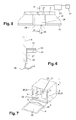
- FIG. 4 is a perspective view of a door with a ledge for the laboratory mixer disclosed herein;
- FIG. 5 is an amplified partial top plan view of the ledge of FIG. 4 ;
- FIG. 6 is an amplified partial sectional view of the ledge taken along the line VI-VI in FIG. 5 ;
- FIG. 7 is a perspective view of an alternative laboratory mixer according to the invention.
- FIGS. 1 through 3 an embodiment of the invention disclosed herein is depicted in FIGS. 1 through 3 in the form of a mixer for sample preparation, which is indicated generally at 1 .
- the illustrated mixer 1 includes mixing members 5 positioned in a mixing chamber 3 and delineated by an enclosure 2 .
- the mixing members 5 allow a bag 10 and the contents of the bag 10 , such as a sample and a diluent solution, to be pressed, retained, and ultimately mixed by a pressing against a supporting surface 43 of the enclosure 2 in the mixer 1 .
- the bag 10 can, for instance, be seen in FIGS. 2 and 3 .
- the mixing members 5 in this embodiment can be reciprocated toward and away from the supporting surface 43 to selectively, and with adjustable pressure, compress the bag 10 and its contents against the supporting surface 43 and, in doing so, to mix the contents of the bag 10 .
- the mixing members 5 are plates or blades whose contact surfaces with the bag 10 are generally parallel to the supporting surface 43 .
- the mixing members 5 may alternatively be referred to as retaining elements, plates, or blades or mixing plates or blades 5 .
- a mixing member actuation and control apparatus 51 can be such that, when one mixing member 5 moves toward the support surface 43 and increases its compression of the bag 10 , another mixing member 5 can deviate away from the supporting surface 43 and decrease its compression of the bag.
- the actuation and control apparatus 51 could pursue multiple different forms within the scope of the invention.
- the actuation and control apparatus 51 can selectively reciprocate or otherwise move the mixing members 5 in an alternating, simultaneous, intermittent, continuous or other movement pattern.
- the mixing members 5 consist of two mixing plates or blades. At least in certain practices of the invention, the supporting surface 43 and the mixing members 5 can be generally vertically disposed with generally vertically disposed plate surfaces. A tank 6 can be positioned below the mixing members 5 to collect leakage from the mix of the sample and diluent solution.
- the enclosure 2 of the mixer 1 can retain an access door 4 .
- the access door 4 can be designed as an access path to the mixing chamber 3 and can retain the supporting surface 43 .
- the door 4 which can be a glass door, is positioned vertically when closed for mixing, and pivots downwardly about a horizontal hinge axis to reach an opening position, such as a position of a 70° inclination, to permit insertion and removal of a bag 10 as shown, for instance, in FIG. 2 , and even to a horizontal position for cleaning as shown, for instance, in FIG. 1 .
- one or more liquid detectors 20 can be located inside the enclosure 2 of the mixer 1 to detect liquids, such as the diluent solution, that may have leaked outside of the bag 10 .
- the liquid detector or detectors 20 can include at least one sensor 21 practically positioned and retained to increase its chances of being in contact with any diluent solution dripping from a bag 10 that is breached during mixing.
- the sensor 21 can transmit a signal to a controlling system, which can include an electronic card, to trigger, for example, cancellation of the mixing operation and/or an audible and/or a visual alarm to alerts the user that preparation has failed.
- the door 4 retains a ledge 41 .
- the ledge 41 can act as a vertical support for the bottom of the bag 10 during mixing.
- the ledge 41 can hold the bag 10 in position against the operative mixing members 5 .
- the ledge 41 could, for example, extend generally perpendicularly from the supporting surface 43 of the door 4 .
- FIG. 2 shows a user inserting a bag 10 containing a sample and a diluent solution along an insertion path generally indicated at 11 .
- the diluent solution could generally be a saline solution, such as physiological serum.
- the bag 10 can be inserted into the mixer 1 to permit a homogenization of the mixture before microbiological analysis.
- the door 4 being able to be opened, the user may slide the bag 10 along the door 4 to the ledge 41 . The user can then close the door 4 of the mixer 1 before activating the mixing members 5 .
- FIG. 3 shows the mixer 1 as it might appear during the mixing process.
- the door 4 is closed, and the bag 10 is in contact with the door 4 , the ledge 41 , and at least one of the mixing members 5 .
- the mixing members 5 can intermittently, alternatingly, or otherwise press against the bag 10 along a generally horizontal trajectory, compressing it against the supporting surface 43 of the door 4 .
- the sample can then be gradually grinded after each successive contact by the mixing members 5 and diluted in the diluent solution by means of the homogenization process.
- the ledge 41 can be located at a given height from the bottom of the mixer 1 .
- the ledge 6 can overlie the tank 6 in such a manner that any leaking solution not retained by the ledge 41 will tend to flow into the tank 6 located at the bottom of the mixing chamber 3 .
- the inner face of the access door 4 can be seen perhaps most clearly in FIG. 4 .
- the ledge 41 affixed to the inner face of the access door 4 .
- the ledge 41 more particularly at least the upper face of the ledge 41 , can be seen to have a low-point 44 where any leaking liquid would tend to gather.
- the low-point 44 is located in an intermediate position, preferably at about midway along the ledge 41 .
- the ledge 41 can be shaped in a V-shape and can offer two slopes of similar length and steepness. The ledge 41 thus offers a support to the bottom of the bag 10 against gravity while controlling the flow of diluent solution or the sample mixed with it in case of a leak or a burst.
- At least one sensor 21 can be located at or near the low-point 44 of the ledge 41 .
- the sensor 21 can have a sensing face horizontally turned face-up.
- the ledge 41 can be channel-shaped and can offer one or more outboard ridges or sills 42 opposite to the supporting surface 43 .
- the sills 42 can offer better guidance of liquid dripping from the bag 10 and the ledge 41 toward the at least one sensor 21 . With that, the chances of an early detection of any leak of liquid is increased, and diluent solution is guided toward but does not arbitrarily leak directly into the tank 6 . Consequently, the intersection of the two slopes of the ledge 41 corresponds to a discharge collector with the ledge 41 acting as a through-way or a spillway.
- the sensor or sensors 21 could, for example, be an electrically conductive sensor 21 .
- the sensor 21 can, by way of example and not limitation, include two electrodes 24 fixed on an isolating substrate 22 that are normally isolated from one another. A gap 26 is established between the electrodes 24 . When a drip of liquid bridges the gap 26 , it connects the electrodes 24 electrically. A current is sent from one electrode 24 to the other and can be detected by an electrical monitoring system 29 of the mixer 1 , which is shown schematically. This detection can generate the emission of an alarm signal from an alarm 30 and, additionally or alternatively, a shutdown of the mixing members 5 .
- the gap between the two electrodes 24 which means the width of the gap 26 , can be less than or equal to the diameter of a drip of the diluent solution. This way, any drip can be detected, and the mixing members 5 can be stopped instantly, whether manually by a user or automatically. Leaking diluent solution can be prevented from continuing to spread in the mixing chamber 3 .
- the form of the electrodes 24 can be chosen so that the developed length of the gap 26 would as great as possible.
- the gap 26 can, for example, be made of one or several turns or even a sinuous shape of electrically conductive material.
- each electrode 24 has a comb shape and the two combs face each other, interleaved to define a gap 26 that is sinuous and of a roughly equal width.
- Conductors 27 can connect the electrodes 24 to the electrical monitoring system 29 located in the mixer 1 .
- the sensor 21 is fixed on a flexible substrate 22 which is itself mounted on the ledge 41 as can be seen in the cross-sectional view of FIG. 6 .
- the substrate 22 is extended by a flexible tab 23 that supports the conductors 27 , made flexible, and connecting the sensor 21 to the electric monitoring system 29 installed in a static position in the mixer 1 .
- the tab 23 bearing the conductors 27 can go to the articulation axis of the door 4 and form around it a loop 28 that can bend elastically when the door 4 is manipulated.
- one or more sensors 21 can be chosen from the group formed by capacitive, inductive, and optical sensors.
- At least one sensor 21 can be retained on one of the surfaces delineating the mixing chamber 3 adjacent to the door 4 .
- a sensor 21 can be located on each lateral wall of the mixing chamber 3 adjacent to the door 4 .
- the sensor or sensors 21 can be close to the door 4 and, additionally or alternatively, near the mixing members 5 when they are on deployed in position for operation in contact with the bag 10 . This embodiment is especially advantageous in case the bag 10 bursts and diluent solution is sprayed about the chamber 3 .
- a sensor 21 can be mounted on a mixing member 5 or on each one of the mixing members 5 as shown, for instance, in FIG. 7 .
- the sensor or sensors 21 can be disposed on one or both of the mixing elements 5 and, thus, in direct contact with the bag 10 during operation of the mixer 1 .
- a sensor 21 could also be located on, in, or at the bottom of the tank 6 , such as directly below a discharge drain of the ledge 41 .
- the sensor 21 can be movable to enable extraction from the tank 6 .
- One or more sensor 21 could additionally or alternatively be set on the door 4 . Such a sensor 21 could extend the entire width of the door 4 so that, wherever the liquid may drip along the door 4 , it would be detected.
- each loop of a first spiral can extend between two successive loops of a second spiral.
- at least one sensor 21 could be movable between two preparations.
Landscapes
- Chemical & Material Sciences (AREA)
- Chemical Kinetics & Catalysis (AREA)
- Engineering & Computer Science (AREA)
- Analytical Chemistry (AREA)
- General Health & Medical Sciences (AREA)
- Physics & Mathematics (AREA)
- Health & Medical Sciences (AREA)
- Life Sciences & Earth Sciences (AREA)
- Mechanical Engineering (AREA)
- Biochemistry (AREA)
- Food Science & Technology (AREA)
- General Physics & Mathematics (AREA)
- Immunology (AREA)
- Pathology (AREA)
- Accessories For Mixers (AREA)
- Sampling And Sample Adjustment (AREA)
- Mixers With Rotating Receptacles And Mixers With Vibration Mechanisms (AREA)
- Investigating Or Analyzing Materials By The Use Of Electric Means (AREA)
- Apparatus Associated With Microorganisms And Enzymes (AREA)
Applications Claiming Priority (2)
| Application Number | Priority Date | Filing Date | Title |
|---|---|---|---|
| FR1361085 | 2013-11-13 | ||
| FR1361085A FR3012980B1 (fr) | 2013-11-13 | 2013-11-13 | Malaxeur de laboratoire |
Publications (2)
| Publication Number | Publication Date |
|---|---|
| US20150131404A1 US20150131404A1 (en) | 2015-05-14 |
| US9682351B2 true US9682351B2 (en) | 2017-06-20 |
Family
ID=49876903
Family Applications (1)
| Application Number | Title | Priority Date | Filing Date |
|---|---|---|---|
| US14/539,300 Active 2035-04-04 US9682351B2 (en) | 2013-11-13 | 2014-11-12 | Laboratory mixer |
Country Status (6)
| Country | Link |
|---|---|
| US (1) | US9682351B2 (zh) |
| JP (1) | JP6382075B2 (zh) |
| KR (1) | KR102292550B1 (zh) |
| CN (1) | CN104474952B (zh) |
| FR (1) | FR3012980B1 (zh) |
| GB (1) | GB2522743B (zh) |
Families Citing this family (4)
| Publication number | Priority date | Publication date | Assignee | Title |
|---|---|---|---|---|
| US11077020B2 (en) * | 2013-05-07 | 2021-08-03 | Biosafe S.A. | Fluid processing based on inflatable bags, mixing system, and method of use thereof |
| KR102068011B1 (ko) * | 2019-04-29 | 2020-01-20 | 조시형 | 자동 패달거리 조절기능을 구비한 균질기 |
| KR102049552B1 (ko) * | 2019-04-29 | 2019-11-27 | 조시형 | 균질기의 동작 방법 및 그 장치 |
| CN113908753B (zh) * | 2021-10-08 | 2023-09-29 | 瑞昌市溢香农产品有限公司 | 一种鸭蛋腌制液的混合系统 |
Citations (4)
| Publication number | Priority date | Publication date | Assignee | Title |
|---|---|---|---|---|
| US4907723A (en) * | 1986-03-10 | 1990-03-13 | Solly Katz | Fluid dispenser including an arrangement to impart wave-like motion to the store fluid |
| US6327895B1 (en) * | 1997-07-09 | 2001-12-11 | Gambro Lundia Ab | Method and arrangement for integrity-testing of a tube-set for use in a cycler for peritoneal dialysis |
| US20050162811A1 (en) * | 2004-01-26 | 2005-07-28 | Yamaichi Electronics Co., Ltd. | Comb-shaped actuator |
| US20070220956A1 (en) * | 2006-03-22 | 2007-09-27 | Terentiev Alexandre N | Apparatus and methods for leak detection in bioprocessing bags |
Family Cites Families (9)
| Publication number | Priority date | Publication date | Assignee | Title |
|---|---|---|---|---|
| WO1997043039A1 (en) * | 1996-05-13 | 1997-11-20 | Filtaflex Limited | Bag beating microbe suspender with vibrating beater |
| US6267498B1 (en) * | 1999-03-05 | 2001-07-31 | Labplas Inc. | Device for blending the contents of a bag |
| US7722839B2 (en) * | 2001-10-11 | 2010-05-25 | Cytotherm, L.P. | Apparatus and method for thawing biological materials |
| JP2003185524A (ja) * | 2001-12-17 | 2003-07-03 | Tatsuhiko Matsuura | 液漏れ検査装置 |
| CA2386696A1 (en) * | 2002-05-17 | 2003-11-17 | Unknown | Spillage collection bag for device that blend the contents of a sampling bag |
| CA2428865C (en) * | 2002-05-17 | 2007-09-11 | Labplas Inc. | Spillage collection bag for devices that blend the contents of a sampling bag |
| US20090188211A1 (en) * | 2008-01-25 | 2009-07-30 | Xcellerex, Inc. | Bag wrinkle remover, leak detection systems, and electromagnetic agitation for liquid containment systems |
| WO2009093995A1 (en) * | 2008-01-25 | 2009-07-30 | Xcellerex, Inc. | Bag wrinkel remover, leak detection systems, and electromagnetic agitation for liquid containment systems |
| KR200446052Y1 (ko) * | 2008-11-20 | 2009-09-21 | 김옥선 | 분쇄기 |
-
2013
- 2013-11-13 FR FR1361085A patent/FR3012980B1/fr active Active
-
2014
- 2014-11-10 GB GB1419972.3A patent/GB2522743B/en active Active
- 2014-11-12 KR KR1020140157475A patent/KR102292550B1/ko active IP Right Grant
- 2014-11-12 US US14/539,300 patent/US9682351B2/en active Active
- 2014-11-13 CN CN201410637217.3A patent/CN104474952B/zh active Active
- 2014-11-13 JP JP2014230539A patent/JP6382075B2/ja active Active
Patent Citations (4)
| Publication number | Priority date | Publication date | Assignee | Title |
|---|---|---|---|---|
| US4907723A (en) * | 1986-03-10 | 1990-03-13 | Solly Katz | Fluid dispenser including an arrangement to impart wave-like motion to the store fluid |
| US6327895B1 (en) * | 1997-07-09 | 2001-12-11 | Gambro Lundia Ab | Method and arrangement for integrity-testing of a tube-set for use in a cycler for peritoneal dialysis |
| US20050162811A1 (en) * | 2004-01-26 | 2005-07-28 | Yamaichi Electronics Co., Ltd. | Comb-shaped actuator |
| US20070220956A1 (en) * | 2006-03-22 | 2007-09-27 | Terentiev Alexandre N | Apparatus and methods for leak detection in bioprocessing bags |
Also Published As
| Publication number | Publication date |
|---|---|
| KR20150055593A (ko) | 2015-05-21 |
| GB201419972D0 (en) | 2014-12-24 |
| US20150131404A1 (en) | 2015-05-14 |
| CN104474952A (zh) | 2015-04-01 |
| KR102292550B1 (ko) | 2021-08-23 |
| FR3012980B1 (fr) | 2015-11-13 |
| GB2522743A (en) | 2015-08-05 |
| JP6382075B2 (ja) | 2018-08-29 |
| FR3012980A1 (fr) | 2015-05-15 |
| JP2015093274A (ja) | 2015-05-18 |
| CN104474952B (zh) | 2017-07-18 |
| GB2522743B (en) | 2018-04-11 |
Similar Documents
| Publication | Publication Date | Title |
|---|---|---|
| US9682351B2 (en) | Laboratory mixer | |
| JP7006727B2 (ja) | 生体試料用インピーダンス測定装置および生体試料用インピーダンス測定システム | |
| EP1743171B1 (en) | Mechanical device for mixing a fluid sample with a treatment solution | |
| EP3289331B1 (en) | Portable organic molecular sensing device and method | |
| CN111278987B (zh) | 以高拾取和脱落效率收集有害污染物的采样系统和技术 | |
| US11789007B2 (en) | Test barrel for placing test paper card | |
| US5254311A (en) | Continuous multinominal analysis method and apparatus | |
| US10533995B2 (en) | System and method for detection of target substances | |
| AU2018337027A1 (en) | Hazardous contaminant collection kit and rapid testing | |
| KR101591308B1 (ko) | 절취수단을 구비한 시료채취 장치 및 이를 이용한 시료채취 방법 | |
| EP3328286B1 (en) | Disposable container of 30 or 90 ml for the storage and transportation of human tissue samples or organs to be subjected to histological examination | |
| KR102378607B1 (ko) | 신생아 스크리닝을 위한 출생 포인트 시스템 및 기기, 생화학 카트리지, 및 방법들 | |
| EP2479562A1 (en) | Ion selective electrode cartridge | |
| US11796553B2 (en) | Automatic analysis system | |
| EP2952903B1 (en) | Automated analyzer | |
| EP2530473A1 (en) | Automatic analyzing device | |
| CN203990677U (zh) | 一种试剂瓶遮光装置以及分析设备 | |
| US10073111B2 (en) | Automatic analysis device | |
| CN214668609U (zh) | 一种三唑酮检测盒 | |
| CN203870026U (zh) | 一种农药残毒快速检测卡 | |
| CN104121966B (zh) | 一种外测式液位检测装置及方法 | |
| CN212213762U (zh) | 用于收集和保存活检样本的容器 | |
| CN207268707U (zh) | 用于安放试纸插卡的检测装置 | |
| JPH11271319A (ja) | 液面検出機能を備えた自動分析装置 | |
| GR1010539B (el) | Συσκευη ταχειας ηλεκτροχημικης ανιχνευσης υπολειμματων φυτοπροστατευτικων προϊοντων και πλαστικοποιητων |
Legal Events
| Date | Code | Title | Description |
|---|---|---|---|
| AS | Assignment |
Owner name: INTERSCIENCE, FRANCE Free format text: ASSIGNMENT OF ASSIGNORS INTEREST;ASSIGNOR:JALENQUES, EMMANUEL;REEL/FRAME:034163/0582 Effective date: 20141112 |
|
| STCF | Information on status: patent grant |
Free format text: PATENTED CASE |
|
| MAFP | Maintenance fee payment |
Free format text: PAYMENT OF MAINTENANCE FEE, 4TH YR, SMALL ENTITY (ORIGINAL EVENT CODE: M2551); ENTITY STATUS OF PATENT OWNER: SMALL ENTITY Year of fee payment: 4 |