US968097A - Davenport. - Google Patents
Davenport. Download PDFInfo
- Publication number
- US968097A US968097A US55879110A US1910558791A US968097A US 968097 A US968097 A US 968097A US 55879110 A US55879110 A US 55879110A US 1910558791 A US1910558791 A US 1910558791A US 968097 A US968097 A US 968097A
- Authority
- US
- United States
- Prior art keywords
- arm
- pin
- bracket
- pad
- base
- Prior art date
- Legal status (The legal status is an assumption and is not a legal conclusion. Google has not performed a legal analysis and makes no representation as to the accuracy of the status listed.)
- Expired - Lifetime
Links
- 238000010276 construction Methods 0.000 description 3
- 238000000926 separation method Methods 0.000 description 2
- 239000004744 fabric Substances 0.000 description 1
- 230000000717 retained effect Effects 0.000 description 1
- 230000003313 weakening effect Effects 0.000 description 1
Images
Classifications
-
- A—HUMAN NECESSITIES
- A47—FURNITURE; DOMESTIC ARTICLES OR APPLIANCES; COFFEE MILLS; SPICE MILLS; SUCTION CLEANERS IN GENERAL
- A47C—CHAIRS; SOFAS; BEDS
- A47C17/00—Sofas; Couches; Beds
- A47C17/04—Seating furniture, e.g. sofas, couches, settees, or the like, with movable parts changeable to beds; Chair beds
- A47C17/16—Seating furniture changeable to beds by tilting or pivoting the back-rest
- A47C17/17—Seating furniture changeable to beds by tilting or pivoting the back-rest with coupled movement of back-rest and seat
- A47C17/175—Seating furniture changeable to beds by tilting or pivoting the back-rest with coupled movement of back-rest and seat with tilting or lifting seat-back-rest pivot
- A47C17/1756—Seating furniture changeable to beds by tilting or pivoting the back-rest with coupled movement of back-rest and seat with tilting or lifting seat-back-rest pivot by pivoted linkages
Definitions
- My invention relates to davenports
- the back and seat may be arranged to form a bed or couch.
- my invention relates to the means for connecting the pad, usually the portion forming the back, to the base or box of the device.
- a two part pad is provided one part of which forms the seat and the other
- the seat portion is slidably mounted upon the base, which is usually of box form, and the back portion is hingedly connected thereto, so that the seat may he slid forwardly and the back dropped to horizontal position, together forming a mattress when the device is to be used as a couch or bed.
- the back portion of the pad and the base are connected by an arm pivotally connected at its ends to brackets secured to said back and base respectively.
- this has been a substantially permanent connection and the pad can only be removed from the base after having removed the screws which hold the bracket to the pad.
- the object of my invention is to provide improved means for attaching the pad to the base whereby the pad may be readily and quickly removed when desired and as readily secured in place.
- My invention consists generally in a dav enport provided .with the connecting arm and brackets as above mentioned equipped with a detachable connection between said arm and one of the brackets whereby said Patented Aug. 23, 1910'.
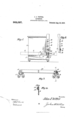
- Fig. 2 is a detail elevation of the end of the back forming pad
- Fig. 3 is an elevation upon an enlarged scale of'the connecting arm and brackets, and illustrating a modified manner of securing the arm to the bracket pin
- Fig. 4 is a section on the line of Fig. 3.
- the seat portion 3 is preferably hingedly connected to the back portion 4 as at 5, the fabric covering of the pad forming'the hinge.
- the seat 3 is slidably mounted on the I 7 base 1 in order that the same may be drawn forward when it is desired to use the device as a bed, and the back portion 4 swings down behind the same and into a plane therewith as shown in dotted lines in Fig. 1.
- a bracket 6 is secured by screws 7 to the base 1 and a similar bracket 8 is secured to the back portion 4 by screws 9.
- the portions of the device so far de scribed are similar to those in general use and no claim is made to the same.
- the pivotal connections between the arm 10 and the bracket-s are permanent and it is therefore necessary, in order to remove the pad from the base, to remove the screws 9, and I have found that after the screws 9 have been removed and replaced a number of times the screw holes in the portion 4 become so worn as to prevent the bracket 8 from being securely fastened to the back.
- brackets 6 and 8 preferably the latter, whereby said arm and bracket may be readily separated when desired and as readily secured together.
- the permanent pivotal connection between the opposite bracket and the arm 10 may be retained, and in practice I prefer such construction.
- a pin 12 Extending outwardly from the face of the bracket 8 is a pin 12 upon which the adj acent end of the arm 10 is pivotally mounted, saidend being provided with an aperture 13 to receive said pin, and a pin 14 extends transversely through the end of the pin 12 to normally hold the end of the arm on said pin.
- the pin 14 may be the end of a rod 15 slidably mounted on the end of the pad 1 as shown in Figs. 1 and 2 or it may be a cotter pin 14 as shown in Figs. 3 and 4.
- the former construction affords ease of manipulation and when such is employed the rod 15 is-slidably mounted in eyes or guides 16 close against the ends of the pad 4: and is off-set as shown to form the pin 14 to extend through the aperture in the pin 12.
- connection between the arm 10 and bracket 8 is as strong and as durable as the permanent connection heretofore provided, and that by removing the pin 14; the arm 10 may be detached from the bracket 8 and hence from the pad, permitting the pad to be removed from the base, and that the parts may be as readily secured together.
- the arm and brackets are to be arranged upon each end of the device.
- a base in combination with a bracket secured to said base, an arm pivotally connected at one end to said bracket, a second bracket secured to said back, a pin projecting from said second bracket, one end of said arm being perforated to receive said pin, and a rod slidably mounted on the end of said back, the end of said rod forming a pin to extend through the outer end of the first said pin to retain said arm on said pin, substantially as described.
Landscapes
- Health & Medical Sciences (AREA)
- General Health & Medical Sciences (AREA)
- Nursing (AREA)
- Invalid Beds And Related Equipment (AREA)
Description
J. J. VETTER.
DAVENPORT.
APPLICATION FILED MAY 2, 1910.
' Patented-Mg. 23, 1910.
' part the back of the device.
JOHN J. VETTER, OF INDIANAPOLIS, INDIANA.
DAVENPORT.
Specification of Letters Patent.
Application filed May 2, 1910. Serial No. 558,791.
To all whom it may concern:
Be it known that I, JOHN J. VETTER, a citizen of the United States, residing at Indianapolis, county of Marion, and State of Indiana, have invented certain new and useful Improvements in Davenports, of which the following is a specification.
My invention relates to davenports, and
particularly to folding davenports wherein the back and seat may be arranged to form a bed or couch.
More specifically my invention relates to the means for connecting the pad, usually the portion forming the back, to the base or box of the device.
In davenports of the character under consideration a two part pad is provided one part of which forms the seat and the other The seat portion is slidably mounted upon the base, which is usually of box form, and the back portion is hingedly connected thereto, so that the seat may he slid forwardly and the back dropped to horizontal position, together forming a mattress when the device is to be used as a couch or bed. To prevent separation of the pad from the base, the back portion of the pad and the base are connected by an arm pivotally connected at its ends to brackets secured to said back and base respectively. Heretofore this has been a substantially permanent connection and the pad can only be removed from the base after having removed the screws which hold the bracket to the pad. Consequently in shipping or handling the davenports they must be packed into a single crate or bundle, which on account of its bulk and weight is difficult to handle and expensive to move or ship, or, one of the brackets must be removed from its respective parts and when the device is again set up it must be reattached thereto. When the latter expedient is resorted to, the screw holes soon become, after several moves, so worn that the screws will not securely hold the brackets in place.
The object of my invention is to provide improved means for attaching the pad to the base whereby the pad may be readily and quickly removed when desired and as readily secured in place.
Other objects will appear hereinafter.
My invention consists generally in a dav enport provided .with the connecting arm and brackets as above mentioned equipped with a detachable connection between said arm and one of the brackets whereby said Patented Aug. 23, 1910'.
illustrating in dotted lines the pad extended to form a mattress when the device is to be used as a bed, Fig. 2 is a detail elevation of the end of the back forming pad, Fig. 3 is an elevation upon an enlarged scale of'the connecting arm and brackets, and illustrating a modified manner of securing the arm to the bracket pin, and Fig. 4 is a section on the line of Fig. 3.
Referring now to the drawings 1 indicates the base or box, 2 an end arm thereof, :1;
and 3 and 4 the seat portion and back portion respectively of the pad. The seat portion 3 is preferably hingedly connected to the back portion 4 as at 5, the fabric covering of the pad forming'the hinge.
The seat 3 is slidably mounted on the I 7 base 1 in order that the same may be drawn forward when it is desired to use the device as a bed, and the back portion 4 swings down behind the same and into a plane therewith as shown in dotted lines in Fig. 1.
A bracket 6 is secured by screws 7 to the base 1 and a similar bracket 8 is secured to the back portion 4 by screws 9. An arm 10 pivotally connected at its ends to the brackets 6 and 8 respectively normally prevents separation of the pads 3 and 4 from the base. The portions of the device so far de scribed are similar to those in general use and no claim is made to the same. As now constructed the pivotal connections between the arm 10 and the bracket-s are permanent and it is therefore necessary, in order to remove the pad from the base, to remove the screws 9, and I have found that after the screws 9 have been removed and replaced a number of times the screw holes in the portion 4 become so worn as to prevent the bracket 8 from being securely fastened to the back.
In carrying out my invention I provide a detachable connection between one of the brackets 6 and 8, preferably the latter, whereby said arm and bracket may be readily separated when desired and as readily secured together. The permanent pivotal connection between the opposite bracket and the arm 10 may be retained, and in practice I prefer such construction.
11 indicates a rivet extending through the bracket 6 and the respective end of the arm 10, forming the permanent pivotal connection.
Extending outwardly from the face of the bracket 8 is a pin 12 upon which the adj acent end of the arm 10 is pivotally mounted, saidend being provided with an aperture 13 to receive said pin, and a pin 14 extends transversely through the end of the pin 12 to normally hold the end of the arm on said pin. The pin 14 may be the end of a rod 15 slidably mounted on the end of the pad 1 as shown in Figs. 1 and 2 or it may be a cotter pin 14 as shown in Figs. 3 and 4. The former construction affords ease of manipulation and when such is employed the rod 15 is-slidably mounted in eyes or guides 16 close against the ends of the pad 4: and is off-set as shown to form the pin 14 to extend through the aperture in the pin 12.
It is obvious that with this construction the connection between the arm 10 and bracket 8 is as strong and as durable as the permanent connection heretofore provided, and that by removing the pin 14; the arm 10 may be detached from the bracket 8 and hence from the pad, permitting the pad to be removed from the base, and that the parts may be as readily secured together. In taking the da-venport apart or assembling the same, it is not necessary to remove any screws, or to use any tools, and further the device may be taken apart and put together as frequently as desired without weakening any of the parts. It is to be understood that the arm and brackets are to be arranged upon each end of the device.
Having described my invention what I claim as new and desire to secure by Letters Patent is 1. In a davenport, a base, a seat and a back, in combination with a bracket secured to said base, an arm pivotally connected at one end to said bracket, a second bracket secured to said back, a pin projecting from said second bracket, one end of said arm being perforated to receive said pin, and a pin extending through the outer end of the first. said pin to retain said arm on said pin, substantially as described.
2. In a davenport, a base, a seat and a back, in combination with a bracket secured to said base, an arm pivotally connected at one end to said bracket, a second bracket secured to said back, a pin projecting from said second bracket, one end of said arm being perforated to receive said pin, and a rod slidably mounted on the end of said back, the end of said rod forming a pin to extend through the outer end of the first said pin to retain said arm on said pin, substantially as described.
In testimony whereof I have signed my name to this specification in the presence of two subscribing witnesses.
JOHN J. VETTER.
WVitnesses:
ERLE S. KINNEAR, JOSEPH J. KREBER.
Priority Applications (1)
| Application Number | Priority Date | Filing Date | Title |
|---|---|---|---|
| US55879110A US968097A (en) | 1910-05-02 | 1910-05-02 | Davenport. |
Applications Claiming Priority (1)
| Application Number | Priority Date | Filing Date | Title |
|---|---|---|---|
| US55879110A US968097A (en) | 1910-05-02 | 1910-05-02 | Davenport. |
Publications (1)
| Publication Number | Publication Date |
|---|---|
| US968097A true US968097A (en) | 1910-08-23 |
Family
ID=3036488
Family Applications (1)
| Application Number | Title | Priority Date | Filing Date |
|---|---|---|---|
| US55879110A Expired - Lifetime US968097A (en) | 1910-05-02 | 1910-05-02 | Davenport. |
Country Status (1)
| Country | Link |
|---|---|
| US (1) | US968097A (en) |
-
1910
- 1910-05-02 US US55879110A patent/US968097A/en not_active Expired - Lifetime
Similar Documents
| Publication | Publication Date | Title |
|---|---|---|
| US1117436A (en) | Butcher's gambrel. | |
| US660316A (en) | Garment-hanger. | |
| US1039699A (en) | Rocking-horse. | |
| US664542A (en) | Playing-board and guard for infants' chairs. | |
| US926472A (en) | Portable camp-chair. | |
| US855520A (en) | Combination furniture. | |
| US953872A (en) | Chair. | |
| US1374467A (en) | Seat-raising attachment for theater-chairs or the like | |
| US888865A (en) | Sofa-bed. | |
| US939824A (en) | Folding table. | |
| US751010A (en) | Bedclothing and mattress clamp | |
| US1008101A (en) | Feed-bag and holder. | |
| US822788A (en) | Protector for horses' tails. | |
| US955005A (en) | Horse-feeder. | |
| US1113573A (en) | Folding or camp chair. | |
| US990515A (en) | Garment-hanger. | |
| US1064306A (en) | Davenport. | |
| US1074960A (en) | Wagon-seat. | |
| US879784A (en) | Feed-bucket. | |
| US1229359A (en) | Harness-rack. | |
| US1079729A (en) | Ship's boat. | |
| US883330A (en) | Chair attachment. | |
| US1025601A (en) | Grain-guard for wagons. | |
| US1227906A (en) | Hat-hanger. | |
| US696685A (en) | Trunk. |