US9678699B2 - Communication apparatus and method of controlling the same - Google Patents
Communication apparatus and method of controlling the same Download PDFInfo
- Publication number
- US9678699B2 US9678699B2 US14/709,734 US201514709734A US9678699B2 US 9678699 B2 US9678699 B2 US 9678699B2 US 201514709734 A US201514709734 A US 201514709734A US 9678699 B2 US9678699 B2 US 9678699B2
- Authority
- US
- United States
- Prior art keywords
- communication apparatus
- service
- port
- unit
- wireless connection
- Prior art date
- Legal status (The legal status is an assumption and is not a legal conclusion. Google has not performed a legal analysis and makes no representation as to the accuracy of the status listed.)
- Expired - Fee Related
Links
Images


Classifications
-
- G—PHYSICS
- G06—COMPUTING; CALCULATING OR COUNTING
- G06F—ELECTRIC DIGITAL DATA PROCESSING
- G06F3/00—Input arrangements for transferring data to be processed into a form capable of being handled by the computer; Output arrangements for transferring data from processing unit to output unit, e.g. interface arrangements
- G06F3/12—Digital output to print unit, e.g. line printer, chain printer
- G06F3/1201—Dedicated interfaces to print systems
- G06F3/1278—Dedicated interfaces to print systems specifically adapted to adopt a particular infrastructure
- G06F3/1292—Mobile client, e.g. wireless printing
-
- G—PHYSICS
- G06—COMPUTING; CALCULATING OR COUNTING
- G06F—ELECTRIC DIGITAL DATA PROCESSING
- G06F3/00—Input arrangements for transferring data to be processed into a form capable of being handled by the computer; Output arrangements for transferring data from processing unit to output unit, e.g. interface arrangements
- G06F3/12—Digital output to print unit, e.g. line printer, chain printer
- G06F3/1201—Dedicated interfaces to print systems
- G06F3/1202—Dedicated interfaces to print systems specifically adapted to achieve a particular effect
- G06F3/1222—Increasing security of the print job
-
- G—PHYSICS
- G06—COMPUTING; CALCULATING OR COUNTING
- G06F—ELECTRIC DIGITAL DATA PROCESSING
- G06F3/00—Input arrangements for transferring data to be processed into a form capable of being handled by the computer; Output arrangements for transferring data from processing unit to output unit, e.g. interface arrangements
- G06F3/12—Digital output to print unit, e.g. line printer, chain printer
- G06F3/1201—Dedicated interfaces to print systems
- G06F3/1223—Dedicated interfaces to print systems specifically adapted to use a particular technique
- G06F3/1236—Connection management
-
- H—ELECTRICITY
- H04—ELECTRIC COMMUNICATION TECHNIQUE
- H04N—PICTORIAL COMMUNICATION, e.g. TELEVISION
- H04N1/00—Scanning, transmission or reproduction of documents or the like, e.g. facsimile transmission; Details thereof
-
- H—ELECTRICITY
- H04—ELECTRIC COMMUNICATION TECHNIQUE
- H04N—PICTORIAL COMMUNICATION, e.g. TELEVISION
- H04N1/00—Scanning, transmission or reproduction of documents or the like, e.g. facsimile transmission; Details thereof
- H04N1/00127—Connection or combination of a still picture apparatus with another apparatus, e.g. for storage, processing or transmission of still picture signals or of information associated with a still picture
- H04N1/00132—Connection or combination of a still picture apparatus with another apparatus, e.g. for storage, processing or transmission of still picture signals or of information associated with a still picture in a digital photofinishing system, i.e. a system where digital photographic images undergo typical photofinishing processing, e.g. printing ordering
- H04N1/00137—Transmission
-
- H—ELECTRICITY
- H04—ELECTRIC COMMUNICATION TECHNIQUE
- H04N—PICTORIAL COMMUNICATION, e.g. TELEVISION
- H04N1/00—Scanning, transmission or reproduction of documents or the like, e.g. facsimile transmission; Details thereof
- H04N1/00127—Connection or combination of a still picture apparatus with another apparatus, e.g. for storage, processing or transmission of still picture signals or of information associated with a still picture
- H04N1/00132—Connection or combination of a still picture apparatus with another apparatus, e.g. for storage, processing or transmission of still picture signals or of information associated with a still picture in a digital photofinishing system, i.e. a system where digital photographic images undergo typical photofinishing processing, e.g. printing ordering
- H04N1/00185—Image output
- H04N1/00188—Printing, e.g. prints or reprints
-
- H—ELECTRICITY
- H04—ELECTRIC COMMUNICATION TECHNIQUE
- H04N—PICTORIAL COMMUNICATION, e.g. TELEVISION
- H04N1/00—Scanning, transmission or reproduction of documents or the like, e.g. facsimile transmission; Details thereof
- H04N1/00127—Connection or combination of a still picture apparatus with another apparatus, e.g. for storage, processing or transmission of still picture signals or of information associated with a still picture
- H04N1/00249—Connection or combination of a still picture apparatus with another apparatus, e.g. for storage, processing or transmission of still picture signals or of information associated with a still picture with a photographic apparatus, e.g. a photographic printer or a projector
- H04N1/00251—Connection or combination of a still picture apparatus with another apparatus, e.g. for storage, processing or transmission of still picture signals or of information associated with a still picture with a photographic apparatus, e.g. a photographic printer or a projector with an apparatus for taking photographic images, e.g. a camera
-
- H04W4/008—
-
- H—ELECTRICITY
- H04—ELECTRIC COMMUNICATION TECHNIQUE
- H04W—WIRELESS COMMUNICATION NETWORKS
- H04W4/00—Services specially adapted for wireless communication networks; Facilities therefor
- H04W4/80—Services using short range communication, e.g. near-field communication [NFC], radio-frequency identification [RFID] or low energy communication
Definitions
- the present invention relates to a communication apparatus and a method of controlling the same.
- Wi-Fi Direct registered trademark
- the Wi-Fi Direct standard defines a function for advertising and searching for service information supported by high level applications (service discovery function) as an optional function.
- service discovery function service information held by an electronic device that is to be a communication destination can be obtained before executing connection processing, and when service information has been obtained, it is possible to also obtain port information indicating the port that is to be used by the service, and communication can be performed using that port.
- the communication partner apparatus does not have the service discovery function, it is not possible to obtain port information indicating the port that is to be used by the service provided by the communication partner apparatus, and therefore communication cannot be performed using that port, and there is a risk of a decrease in user convenience.
- the ports are opened, there is a possibility of a connection being established by an unintended apparatus, which leads to a decreased level of security.
- One embodiment of the present invention provides a communication apparatus that raises the level of security while maintaining connectability, as well as a method of controlling the same, and a program.
- a communication apparatus comprising: a connection unit configured to perform wireless connection processing for performing wireless communication with another communication apparatus; a specifying unit configured to specify a service that is to be executed along with the other communication apparatus, in the wireless connection processing performed by the connection unit, using wireless communication that is based on the wireless connection processing; and a control unit configured to perform port control such that a port necessary for execution of the service specified by the specifying unit is opened, and a port not necessary for execution of the service is locked.
- a method of controlling a communication apparatus comprising: a connection step of performing wireless connection processing for performing wireless communication with another communication apparatus; a specifying step of specifying a service that is to be executed along with the other communication apparatus, in the wireless connection processing performed in the connection step, using wireless communication that is based on the wireless connection processing; and a control step of performing port control such that a port necessary for execution of the service specified in the specifying step is opened, and a port not necessary for execution of the service is locked.
- FIG. 1 is a diagram showing an example of a network configuration according to an embodiment.
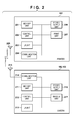
- FIG. 2 is a block diagram showing an example of hardware configurations of a printer and cameras according to the embodiment.
- FIG. 3A is a block diagram of software in the printer according to the embodiment.
- FIG. 3B is a block diagram of software in the cameras according to the embodiment.
- FIG. 4A is a flowchart of processing performed by the printer according to the embodiment.
- FIG. 4B is a flowchart of processing performed by the cameras according to the embodiment.
- FIGS. 5A to 5D are diagrams showing information stored by a memory unit 201 .
- FIG. 6 is a flowchart of processing realized by the printer and the cameras.
- FIG. 1 is a diagram showing an example of the network configuration of a communication system according to the present embodiment.
- a printer 101 is one example of a communication apparatus that includes a communication function, and the printer 101 provides a print function and performs communication compliant with the IEEE 802.11 series, for example.
- a camera 102 and a camera 103 are examples of other communication apparatus that include a communication function, and these cameras 102 and 103 perform communication compliant with the IEEE 802.11 series, for example, with the printer 101 .
- the “communication apparatus” and “other communication apparatuses” referred to here are not limited to the printer 101 and the cameras 102 and 103 , and may be storage devices, mobile phones (including smartphones), PCs, medical devices, and the like.
- the camera 102 can provide a later-described first service, and the camera 103 does not provide the first service.
- FIG. 2 is a block diagram showing an example of the hardware configurations of the printer 101 and the cameras 102 and 103 . Note that in the printer 101 and the cameras 102 and 103 , multiple blocks shown in FIG. 2 may be realized as a single module, and single blocks shown in FIG. 2 may be realized by multiple modules.
- a memory unit 201 is configured by a memory (not shown) such as a read-only ROM or a rewritable RAM.
- the memory unit 201 stores programs (including an OS) for the execution of various later-described operations by a control unit 202 , image data, communication parameters, and various types of information such as port information.
- the memory unit 201 can be a storage medium such as a flexible disk, a hard disk, an optical disk, a magnetic optical disk, a CD-ROM, a CD-R, a magnetic tape, a non-volatile memory, or a DVD.
- the control unit 202 includes a CPU, an MPU, or a computer, and the control unit 202 realizes various types of control in the printer 101 by reading out and executing programs stored in the memory unit 201 .
- the control unit 202 may be provided with an OS (Operating System) and perform overall control of the printer 101 through coordination between the OS and the above-mentioned programs.
- a user interface unit (hereinafter, “UI unit”) 203 causes a display device (not shown) to display various types of information from the control unit 202 , the communication unit 204 , and the memory unit 201 .
- the UI unit 203 also provides the control unit 202 with signals corresponding to various types of operations performed by a user.
- a communication unit 204 performs communication compliant with the IEEE 802.11 series, for example, via an antenna 205 , and specifically receives signals and information from external apparatuses and transmits information and signals from the printer 101 to external apparatuses.
- a power supply unit 206 supplies electrical power to the hardware modules shown in FIG. 2 . Note that although the power supply unit 206 obtains electrical power for supply from a commercial power source in this case, there is no limitation to this, and a configuration having an internal battery is possible.
- a print unit 207 outputs image data stored in the memory unit 201 by printing. Note that image data received from the camera 102 and the camera 103 , which are external apparatuses, via the communication unit 204 can be temporarily stored in the memory unit 201 and output by the print unit 207 .
- a memory unit 211 , a control unit 212 , a communication unit 214 , and an antenna 215 have configurations similar to the memory unit 201 , the control unit 202 , the communication unit 204 , and the antenna 205 of the printer 101 .
- control unit 212 performs various types of control for the cameras 102 and 103 .
- a UI unit 213 provides the control unit 212 with signals corresponding to various types of operations performed by a user, such as a shooting operation and an image transmission operation.
- a power supply unit 216 supplies electrical power to the hardware modules in the cameras 102 and 103 . Note that the power supply unit 216 is normally an internal battery that can be repeatedly used through charging.
- An imaging unit 217 converts a signal obtained by an image pickup device into a digital signal, and supplies the digital signal to the control unit 212 .
- the control unit 212 converts the signal obtained from the imaging unit 217 into an image, and stores the image in the memory unit 211 as image data.
- the communication unit 204 of the printer 101 and the communication units 214 of the cameras 102 and 103 can communicate with each other by wireless communication, and can carry out wireless LAN communication compliant with the IEEE 802.11 series, for example, as previously described.
- FIGS. 3A and 3B show software modules realized by the CPUs of the control units 202 and 212 of the printer 101 and the cameras 102 and 103 reading out and executing programs stored in the memory units 201 and 211 .
- multiple software modules shown in FIG. 3 may be realized as a single software module, and a single software module shown in FIG. 3 may be realized as multiple software modules.
- at least a portion of the software modules shown in FIG. 3 may be realized by hardware modules.
- a dedicated circuit is automatically generated in an FPGA from a program for realizing a software module by using a predetermined compiler, for example, a module realized by software can be realized by hardware, and the processing speed can be increased.
- FPGA is an abbreviation for Field Programmable Gate Array.
- a software module may be realized as a hardware module by forming a gate array circuit, similarly to an FPGA.
- An activation unit 301 activates a first service unit 302 in accordance with an operation instruction from the UI unit 203 .
- the first service unit 302 performs communication with the cameras 102 and 103 via the communication unit 204 , and executes a first service.
- the first service is a service by which, using a second service provided by a second service unit for example, image data is wirelessly transmitted from a camera to the printer, and the printer receives the image data and performs printing based thereon, and the first service is accompanied by port control that will be described later.
- the second service is a specific service such as IPP (Internet Printing Protocol), PictBridge (standard set by the Camera & Imaging Products Association), or DLNA (registered trademark).
- the first service unit 302 includes a lock unit 303 , a determination unit 305 , a halt unit 310 , and an unlock unit 311 .
- the lock unit 303 locks TCP-defined ports that can be exclusively used for communication between the communication unit 204 of the printer 101 and other communication apparatuses (e.g., ports other than well-known ports).
- the determination unit 305 determines whether or not another communication apparatus, such as the camera 102 or 103 , which has requested to perform connection processing with the printer 101 , can provide the first service.
- the halt unit 310 halts the first service unit 302 if the camera that is the other communication apparatus does not provide the first service.
- the unlock unit 311 opens ports by, depending on the situation, unlocking ports locked by the lock unit 303 .
- a search-response unit 304 makes a response to a device search request from another communication apparatus in the vicinity of the printer 101 .
- An inquiry-response unit 306 makes a response to a detailed inquiry regarding services provided by the printer 101 from another communication apparatus (the camera 102 or 103 in this example).
- a connection unit 307 performs wireless connection processing for establishing a wireless connection with another communication apparatus in accordance with a predetermined connection procedure. In the present embodiment, the connection unit 307 executes wireless connection processing in accordance with the connection procedure defined by the Wi-Fi Direct standard.
- the second service unit 308 executes predetermined service processing in coordination with another connected communication apparatus.
- a disconnection unit 309 performs disconnection processing for disconnecting the wireless connection with another communication apparatus after communication has ended.
- a service information provision unit 312 provides information regarding a service compliant with UPnP or mDNS (in this example, the service provided by the second service unit 308 ), and makes responses to inquiries.
- UPnP is an abbreviation for Universal Plug and Play.
- mDNS is an abbreviation for multicast DNS (Domain Name System).
- the first service unit 302 is a platform that operates in a higher layer than the layer in which the connection unit 307 established the wireless connection. Specifically, the communication performed by the first service unit 302 is performed using the wireless connection established by the connection unit 307 . Also, communication may be performed using another service function unit in a higher layer than the first service unit 302 . Furthermore, the layer in which the first service unit 302 operates and the layer in which the connection unit 307 established a wireless connection may be the same layer.
- An activation unit 351 activates a first service unit 352 in the camera.
- the first service unit 352 performs communication with the printer 101 via the communication unit 214 .
- the first service unit 352 includes a determination unit 355 , a halt unit 360 , and an unlock unit 361 .
- the determination unit 355 determines whether or not the printer 101 , which is the communication destination, can provide the first service.
- the halt unit 360 halts the first service unit 352 if the printer 101 , which is the communication apparatus that is the communication destination, does not provide the first service.
- the unlock unit 361 opens ports by, depending on the situation, unlocking ports locked by a lock unit 353 .
- the camera 102 is an apparatus that can provide the first service
- the camera 103 is an apparatus that does not provide the first service. Accordingly, the camera 103 does not include the first service unit 352 .
- a search request unit 354 transmits a device search request, for example, in order to establish a wireless connection (in the present embodiment, a WiFi Direct connection) with a communication apparatus in the vicinity.
- An inquiry unit 356 makes a detailed inquiry regarding services provided by the printer 101 , from the camera 102 or 103 , which is the other communication apparatus, to the printer 101 .
- a connection unit 357 performs wireless connection processing for establishing a wireless connection with the printer 101 , which is a communication apparatus, in accordance with a predetermined connection procedure. In the present embodiment, the connection unit 357 executes wireless connection processing in accordance with the connection procedure defined by the Wi-Fi Direct standard.
- a third service unit 358 executes predetermined service processing in coordination with other connected communication apparatuses.
- the third service unit 358 executes a service for causing the printer 101 to print image data stored in a camera using the service provided by the second service unit 308 of the printer 101 .
- a disconnection unit 359 performs disconnection processing for disconnecting the wireless connection with the printer 101 , which is a communication apparatus, after communication has ended.
- a service information obtaining unit 362 obtains information regarding services compliant with UPnP or mDNS.
- a program corresponding to the flowchart shown in FIG. 4A is stored in the memory unit 201 . Due to this program being read out and executed by the CPU of the control unit 202 , the printer 101 establishes a connection with the camera 102 or the camera 103 by direct communication, and data received from the camera is output by the print unit 207 of the printer 101 . Similarly, in the cameras 102 and 103 , a program corresponding to the flowchart shown in FIG. 4B is stored in the memory unit 211 .
- the camera 102 or the camera 103 establishes a connection with the printer 101 by direct communication, and image data that is to be output by printing by the printer 101 is transmitted to the printer 101 .
- operations related to the first service unit 352 are not executed by the camera 103 due to not having the first service unit 352 . Operations in the case of a connection between the printer 101 and the camera 102 will be described below.
- step S 401 the activation unit 301 of the printer 101 activates the first service unit 302 in accordance with an operation made on the UI unit 203 by a user.
- This operation is an operation for instructing the establishment of a connection, for example.
- the control unit 202 starts apparatus search processing performed by the search-response unit 304 in order to determine the camera with which a wireless connection is to be established.
- the activation unit 351 activates the first service unit 352 in accordance with an operation made on the UI unit 213
- step S 452 the search request unit 354 broadcasts a search signal.
- the camera 102 transmits a search signal for making an apparatus search request, and a connection destination apparatus can be found when the printer 101 makes a response to the search signal.
- the search signal referred to here is a probe request defined in the IEEE 802.11 series, for example.
- step S 403 the search-response unit 304 determines whether or not the search signal from the camera 102 was received, and in the case of determining that the search signal was received, a response signal is transmitted in step S 404 in response to the search signal.
- the response signal referred to here is a probe response defined in the IEEE 802.11 series, for example.
- step S 453 the cameras 102 and 103 wait to receive a response signal in response to the search signal broadcasted by the search request unit 354 . If a response signal is received, the processing from step S 454 onward, which is for the establishment of a wireless connection by the connection unit 357 , is started.
- the camera 102 transmits a signal (inquiry signal) for inquiring about details of the service provided by the printer 101 , and obtains service information.
- the inquiry-response unit 306 of the printer 101 receives the signal (inquiry signal) inquiring about details of the service provided by the printer 101 (step S 405 ), and transmits a response signal for notifying service information regarding all of the services provided by the printer 101 (step S 406 ).
- the inquiry signal referred to here is a service discovery query (hereinafter, “SD query”) defined by the Wi-Fi Direct standard, for example.
- the response signal is a service discovery response (hereinafter, “SD response”) defined by the Wi-Fi Direct standard, for example, and includes service information regarding all of the services provided by the printer 101 .
- examples of the services provided by the printer 101 indicated by the service information include IPP, PictBridge, DLNA (registered trademark), various types of print services, and the like. These services are provided by the second service unit 308 , and are called second services.
- connection unit 307 of the printer 101 and the connection unit 357 of the camera 102 perform connection processing in accordance with a predetermined connection procedure defined by the Wi-Fi Direct standard, for example.
- the connection unit 307 and the connection unit 357 determine which out of the printer 101 and the camera 102 is to operate as the wireless LAN access point (base station), and which is to operate as the wireless LAN client (terminal).
- the apparatus that operates as the wireless LAN access point is called the group owner (hereinafter, “GO”), and the apparatus that operates the wireless LAN client is called the client (hereinafter, “CL”).
- the connection unit 357 of the camera 102 transmits a GO negotiation request as a GO determination signal for determining the printer 101 as the GO.
- the camera 102 which is the apparatus that transmits the GO determination signal, can provide the first service, and transmits information regarding the first service in the GO determination signal.
- an apparatus that does not provide the first service transmits the GO determination signal without information indicating that the first service can be provided.
- an apparatus that does not provide the first service may transmit information indicating that the first service is not provided in the GO determination signal.
- step S 407 the connection unit 307 of the printer 101 receives the above-described GO determination signal.
- step S 408 the determination unit 305 of the first service unit 302 stores information indicating whether or not the first service can be provided in association with the transmission source apparatus in the memory unit 201 , in accordance with whether or not the received GO determination signal includes information regarding the first service.
- FIG. 5A shows a table of information stored in the memory unit 201 .
- the connection unit 307 of the printer 101 transmits a GO determination response signal (GO negotiation response) for determining the GO in response to the received GO determination signal.
- the first service unit 302 includes information indicating that the printer 101 can provide the first service in the GO determination response signal.
- the GO determination response signal transmitted by the connection unit 307 includes information indicating whether or not the first service can be provided.
- the connection unit 357 receives the GO determination response signal
- the first service unit 352 determines whether or not the first service can be provided based on the GO determination response signal that was received. The determination result is then stored in the memory unit 211 .
- step S 457 the camera 102 determines whether the camera 102 or the printer 101 is to be the GO, and transmits the result to the printer 101 as a GO determination confirmation signal.
- the connection unit 357 sets itself as the GO or the CL in accordance with this determination, and then starts the connection processing of step S 458 .
- the GO determination confirmation signal is a GO negotiation confirm signal, for example.
- the connection unit 307 of the printer 101 receives the GO determination confirmation signal in step S 410 , sets itself as the GO or the CL in accordance with the signal, and then starts the connection processing of step S 411 .
- connection establishment processing (step S 411 and step S 458 ) executed between the printer 101 and the camera 102 will be described below with reference to FIG. 6 .
- connection establishment processing is executed in accordance with a predetermined connection procedure defined by the Wi-Fi Direct standard, for example. Note that a program corresponding to this connection establishment procedure is also stored in the memory unit 201 and the memory units 211 , and executed by the control units 202 and 212 .
- step S 602 the GO apparatus is set so as to operate as a registrar that provides communication parameters that are to be used in the wireless network that is to be created by the GO apparatus, and in step S 603 , the GO apparatus provides the communication partner apparatus with the communication parameters.
- the communication parameters that are to be used in the wireless network that is to be created by the GO apparatus include an SSID (network identifier), an encryption key, an encryption system, an authentication key, an authentication system, and a frequency channel.
- the registrar is the apparatus that provides communication parameters defined by WPS (Wi-Fi Protected Setup).
- step S 604 the GO apparatus receives a connection request signal from the communication partner apparatus.
- the connection request signal referred to here is an association request signal defined in the IEEE 802.11 series standard, for example.
- step S 605 the GO apparatus operates as a DHCP server that provides IP addresses, and determines an IP address for the communication partner apparatus, and in step S 606 , provides the communication partner apparatus with the determined IP address.
- step S 607 the CL apparatus is set so as to operate as an enrollee that obtains communication parameters from the GO operating as the registrar, and in step S 608 , receives communication parameters from the registrar. Then, in step S 609 , the CL apparatus transmits a connection request signal defined in the IEEE 802.11 series based on the obtained communication parameters, and connects to the wireless network created by the GO. Then, in step S 610 , the CL apparatus operates as a DHCP client that obtains an IP address, and obtains an IP address from the DHCP server in step S 611 .
- a wireless connection is established by the printer 101 and the camera 102 .
- the lock unit 303 locks all of the TCP-defined ports that can be exclusively used for communication between the communication unit 204 of the printer 101 and the camera that is the other communication apparatuses (e.g., ports other than well-known ports).
- TCP is an abbreviation for Transmission Control Protocol.
- the lock states (locked or unlocked) of the ports are written to a table in the memory unit 201 by the connection unit 307 .
- the lock unit 303 stores, in the memory unit 201 , port information in association with information indicating whether the corresponding port is in the locked state or unlocked state as shown in FIG. 5B .
- FIG. 5B Note that although three ports are illustrated as representative examples in FIG. 5B , there is no limitation to this, and normally more ports are prepared. Locking ports in this way enables reducing the possibility of access by an unintended party. Accordingly, it is possible to reduce the possibility of the processing load borne by the printer 101 becoming unnecessarily large, and it is also possible to improve the level of security.
- step S 413 the determination unit 305 determines whether or not the camera 102 , which is the connected other communication apparatus, can provide the first service. This determination is made by the determination unit 305 reading out the information regarding the first service that is stored in the memory unit 201 in step S 408 . In this case, the connected camera 102 can provide the first service, and therefore the procedure moves to step S 416 .
- step S 416 port information is shared with the camera 102 by an inquiry and notification made regarding information on the port that is to be used in the service performed with the camera 102 , and the unlock unit 311 unlocks the corresponding port based on the shared information.
- the unlock unit 311 changes the information that indicates the lock state of the locked port from the locked state to the unlocked state (open state) as shown in FIG. 5C , and stores this information in the memory unit 201 .
- the port that is to be used in the service here is illustrated as “xxx”.
- the inquiry and notification made regarding the port information are made by the first service units 302 and 352 using a specified port.
- the specified port may be a port that has been determined in advance for the first service, or may be designated in the information regarding the first service that is stored in step S 408 .
- step S 417 the service information provision unit 312 of the printer 101 notifies service information compliant with UPnP (Universal Plug and Play) or mDNS (multicast DNS), for example. Also, if a service inquiry compliant with UPnP or mDNS is made by the camera 102 , the service information provision unit 312 makes a response to the inquiry.
- UPnP Universal Plug and Play
- mDNS multicast DNS
- step S 418 the second service unit 308 executes second service processing in coordination with the third service unit 358 of the connected camera 102 .
- the second service unit 308 receives image data from the camera 102 , and performs print processing based on the received image data.
- the disconnection unit 309 disconnects the connection with the camera 102 , and completes this processing.
- step S 458 when the connection establishment processing performed in step S 458 ends, processing similar to steps S 412 to S 419 in FIG. 4A is executed in order to execute the previously described second service processing in coordination with the printer 101 .
- all of the ports that can be exclusively used for communication with the printer 101 are locked (step S 412 ), and it is determined whether or not the printer 101 can provide the first service based on information stored in step S 456 (step S 413 ). If the printer 101 can provide the first service, the unlock unit 361 of the camera 102 opens a needed port for sharing with the printer 101 (step S 416 ).
- the service information obtaining unit 362 then obtains service information compliant with UPnP or mDNS, for example, from the printer 101 (step S 417 ). Through this processing, the camera 102 can find out that the printer 101 has started a predetermined second service, and use that service.
- the processing up to the establishment of a wireless connection between the camera 103 and the printer 101 and the locking of all ports is similar to the case of the connection with the camera 102 .
- the GO determination signal received from the camera 103 does not include information indicating that the first service can be provided, and information regarding the first service is not stored in the memory unit 201 .
- the processing related to the first service unit 352 in the flowchart in FIG. 4B is not executed.
- step S 413 the determination unit 305 determines whether or not the connected camera can provide the first service. This determination is made by the determination unit 305 reading out information stored in the memory unit 201 . Here, information regarding a predetermined first service is not stored, and therefore it is determined that the camera 103 selected by the user does not provided the first service, and the procedure moves to step S 414 .
- step S 414 the unlock unit 311 unlocks all of the ports that were locked in step S 412 . Also, the unlock unit 311 changes the information that indicates the lock state of the locked ports from the locked state to the unlocked state (open state) as shown in FIG. 5D , and stores this information in the memory unit 201 . Then, in step S 415 , the halt unit 310 halts the first service unit 302 that was activated in step S 401 .
- step S 417 the service information provision unit 312 broadcasts service information compliant with UPnP or mDNS via a port that was unlocked in step S 414 .
- the camera 103 detects this broadcast information and makes an inquiry to the printer 101 for detailed service information, and thus becomes able to execute a predetermined service with the printer 101 .
- step S 418 the second service unit 308 executes predetermined service processing in coordination with the connected camera 103 . Thereafter, when the predetermined service processing is complete, in step S 419 , the disconnection unit 309 disconnects the connection with the camera 103 , and completes this processing.
- connection processing when connection processing is to be performed between one communication apparatus (e.g., a printer) and another communication apparatus (e.g., a camera), information indicating whether or not the other communication apparatus can execute a predetermined service can be received before the connection processing is performed. Then, the sharing of ports used in communication with the other communication apparatus is controlled based on the received information. Accordingly, the locking and unlocking of ports is controlled based on information indicating whether or not a predetermined service can be executed, which is obtained before connection processing, thus making it possible to raise the level of security while maintaining connectability. Also, the first service units 302 and 352 can be provided as applications. For this reason, even with a communication system that cannot use the service discovery function, it is possible to maintain connectability and security by installing and executing the first service units 302 and 352 .
- the one communication apparatus and the other communication apparatus are respectively described as being a printer and a camera in the above embodiment, there is no limitation to this, and the one communication apparatus may be a camera that has an imaging unit and can transmit image data obtained by the imaging unit to the printer, and the other communication apparatus may be the printer. Also, there is no limitation to the combination of a camera and a printer, and the present invention is applicable to any combination of smartphones, PCs, PDAs, storage devices, and the like.
- port locking is performed in accordance with the activation of the first service. This makes it possible to reduce the possibility of access by an unintended party. Accordingly, it is possible to reduce the possibility of the processing load borne by the printer 101 becoming unnecessarily large, and it is also possible to improve the level of security.
- communication apparatuses that can and cannot provide the first service can be distinguished from each other during the processing for determining the GO before performing connection processing.
- the ports that were locked in accordance with the activation of the first service are unlocked, thus making it possible to maintain connectability.
- Embodiment(s) of the present invention can also be realized by a computer of a system or apparatus that reads out and executes computer executable instructions (e.g., one or more programs) recorded on a storage medium (which may also be referred to more fully as a ‘non-transitory computer-readable storage medium’) to perform the functions of one or more of the above-described embodiment(s) and/or that includes one or more circuits (e.g., application specific integrated circuit (ASIC)) for performing the functions of one or more of the above-described embodiment(s), and by a method performed by the computer of the system or apparatus by, for example, reading out and executing the computer executable instructions from the storage medium to perform the functions of one or more of the above-described embodiment(s) and/or controlling the one or more circuits to perform the functions of one or more of the above-described embodiment(s).
- computer executable instructions e.g., one or more programs
- a storage medium which may also be referred to more fully as a
- the computer may comprise one or more processors (e.g., central processing unit (CPU), micro processing unit (MPU)) and may include a network of separate computers or separate processors to read out and execute the computer executable instructions.
- the computer executable instructions may be provided to the computer, for example, from a network or the storage medium.
- the storage medium may include, for example, one or more of a hard disk, a random-access memory (RAM), a read only memory (ROM), a storage of distributed computing systems, an optical disk (such as a compact disc (CD), digital versatile disc (DVD), or Blu-ray Disc (BD)TM), a flash memory device, a memory card, and the like.
Applications Claiming Priority (2)
| Application Number | Priority Date | Filing Date | Title |
|---|---|---|---|
| JP2014102726A JP6363871B2 (ja) | 2014-05-16 | 2014-05-16 | 通信装置、通信装置の制御方法およびプログラム |
| JP2014-102726 | 2014-05-16 |
Publications (2)
| Publication Number | Publication Date |
|---|---|
| US20150331650A1 US20150331650A1 (en) | 2015-11-19 |
| US9678699B2 true US9678699B2 (en) | 2017-06-13 |
Family
ID=54538547
Family Applications (1)
| Application Number | Title | Priority Date | Filing Date |
|---|---|---|---|
| US14/709,734 Expired - Fee Related US9678699B2 (en) | 2014-05-16 | 2015-05-12 | Communication apparatus and method of controlling the same |
Country Status (2)
| Country | Link |
|---|---|
| US (1) | US9678699B2 (ja) |
| JP (1) | JP6363871B2 (ja) |
Families Citing this family (4)
| Publication number | Priority date | Publication date | Assignee | Title |
|---|---|---|---|---|
| JP6172954B2 (ja) * | 2013-01-25 | 2017-08-02 | キヤノン株式会社 | 通信装置、通信装置の制御方法、プログラム |
| JP6789669B2 (ja) * | 2016-05-19 | 2020-11-25 | キヤノン株式会社 | 画像印刷システム、画像処理装置、画像印刷方法、印刷装置、およびプログラム |
| JP6797651B2 (ja) * | 2016-11-30 | 2020-12-09 | キヤノン株式会社 | 印刷装置、印刷装置の制御方法、及びプログラム |
| JP7402697B2 (ja) * | 2020-01-17 | 2023-12-21 | キヤノン株式会社 | 通信装置、制御方法、及びプログラム |
Citations (6)
| Publication number | Priority date | Publication date | Assignee | Title |
|---|---|---|---|---|
| US20020059482A1 (en) * | 2000-04-05 | 2002-05-16 | Koji Ashizaki | Data converting apparatus and method, printing apparatus and method, printing controlling apparatus and method, printing system and method, and data transmitting method |
| US20050190401A1 (en) * | 2004-02-27 | 2005-09-01 | Eiji Ito | Communication control method, communication control apparatus, and data recording medium |
| JP2011035768A (ja) | 2009-08-04 | 2011-02-17 | Ricoh Co Ltd | 撮像装置及び画像共有システム |
| US20110209211A1 (en) * | 2000-03-01 | 2011-08-25 | Printeron Inc. | Multi-stage polling mechanism and system for the transmission and processing control of network resource data |
| US20150020150A1 (en) * | 2013-07-09 | 2015-01-15 | Canon Kabushiki Kaisha | Management apparatus, control method thereof, and storage medium |
| US20150248263A1 (en) * | 2014-03-03 | 2015-09-03 | Ricoh Company, Ltd. | Tools for facilitating printer installation |
Family Cites Families (10)
| Publication number | Priority date | Publication date | Assignee | Title |
|---|---|---|---|---|
| JP3482103B2 (ja) * | 1997-07-29 | 2003-12-22 | シャープ株式会社 | 赤外線通信制御装置および方法 |
| JP2006020071A (ja) * | 2004-07-01 | 2006-01-19 | Canon Inc | 無線通信システム、無線通信装置及びサービス探索方法 |
| JP4535075B2 (ja) * | 2007-03-12 | 2010-09-01 | ブラザー工業株式会社 | ネットワーク装置、およびネットワーク装置用のプログラム |
| JP2009044230A (ja) * | 2007-08-06 | 2009-02-26 | Toshiba Corp | 通信装置およびネットワーク接続管理プログラム |
| JP2013123211A (ja) * | 2011-11-10 | 2013-06-20 | Canon Inc | 通信装置および通信装置の制御方法 |
| JP5860293B2 (ja) * | 2012-01-30 | 2016-02-16 | キヤノン株式会社 | 通信装置、制御方法、及びプログラム |
| CN103581239B (zh) * | 2012-07-27 | 2019-01-22 | 中兴通讯股份有限公司 | 一种设备和服务的发现方法、装置 |
| CN104541569B (zh) * | 2012-08-08 | 2018-12-07 | 三星电子株式会社 | 生成用于Wi-Fi直连服务的P2P群组的方法和装置 |
| JP5348576B2 (ja) * | 2012-10-04 | 2013-11-20 | キヤノンイメージングシステムズ株式会社 | デバイス共有クライアント及びデバイス共有方法 |
| KR102152713B1 (ko) * | 2012-11-05 | 2020-10-26 | 엘지전자 주식회사 | 직접 통신 시스템에서 서비스 탐색 또는 광고 방법 및 이를 위한 장치 |
-
2014
- 2014-05-16 JP JP2014102726A patent/JP6363871B2/ja not_active Expired - Fee Related
-
2015
- 2015-05-12 US US14/709,734 patent/US9678699B2/en not_active Expired - Fee Related
Patent Citations (6)
| Publication number | Priority date | Publication date | Assignee | Title |
|---|---|---|---|---|
| US20110209211A1 (en) * | 2000-03-01 | 2011-08-25 | Printeron Inc. | Multi-stage polling mechanism and system for the transmission and processing control of network resource data |
| US20020059482A1 (en) * | 2000-04-05 | 2002-05-16 | Koji Ashizaki | Data converting apparatus and method, printing apparatus and method, printing controlling apparatus and method, printing system and method, and data transmitting method |
| US20050190401A1 (en) * | 2004-02-27 | 2005-09-01 | Eiji Ito | Communication control method, communication control apparatus, and data recording medium |
| JP2011035768A (ja) | 2009-08-04 | 2011-02-17 | Ricoh Co Ltd | 撮像装置及び画像共有システム |
| US20150020150A1 (en) * | 2013-07-09 | 2015-01-15 | Canon Kabushiki Kaisha | Management apparatus, control method thereof, and storage medium |
| US20150248263A1 (en) * | 2014-03-03 | 2015-09-03 | Ricoh Company, Ltd. | Tools for facilitating printer installation |
Also Published As
| Publication number | Publication date |
|---|---|
| US20150331650A1 (en) | 2015-11-19 |
| JP6363871B2 (ja) | 2018-07-25 |
| JP2015220602A (ja) | 2015-12-07 |
Similar Documents
| Publication | Publication Date | Title |
|---|---|---|
| US9980084B2 (en) | Communication apparatus, method for controlling the same, and storage medium | |
| US10321312B2 (en) | Communication apparatus and control method thereof | |
| JP6281223B2 (ja) | 通信機器 | |
| US10575344B2 (en) | Communication apparatus, communication control method, and storage medium | |
| US10849169B2 (en) | Communication apparatus for connecting to a wireless network using a simple operation | |
| EP2949138B1 (en) | Communication apparatus, method of controlling the same, and program | |
| KR102366312B1 (ko) | 근거리 통신의 재연결을 수행하는 전자 장치 및 그 동작 방법 | |
| US9918300B2 (en) | Communication apparatus, control method thereof, and program | |
| US9678699B2 (en) | Communication apparatus and method of controlling the same | |
| US20200396582A1 (en) | Communication Device Establishing Wireless Connection with Terminal Device and Non-Transitory Computer-Readable Medium for Terminal Device Establishing Wireless Connection with Communication Device | |
| US20160021230A1 (en) | Communication apparatus connectable with external apparatus by wireless communication, method for controlling communication apparatus, and storage medium | |
| US20150334759A1 (en) | Communication apparatus, control method, and storage medium | |
| US10021622B2 (en) | Communication apparatus, control method for communication apparatus, and storage medium | |
| US20170264515A1 (en) | Communication device, control method for communication device, and program | |
| US9313234B2 (en) | Communication device, method for controlling communication device, and storage medium | |
| US9882880B2 (en) | Communication apparatus, method for controlling the same, and storage medium | |
| US10117099B2 (en) | Communication apparatus, method for controlling the same, and program | |
| US9451392B2 (en) | Communication device, controlling method for communication device, and storage medium | |
| US10165609B2 (en) | Communication apparatus, method for controlling communication apparatus, and program | |
| KR20160007259A (ko) | 무선 통신 시스템에서 채널을 선택하기 위한 방법 및 장치 | |
| US20100293300A1 (en) | Communication apparatus, control method of communication apparatus, and program | |
| US10674547B2 (en) | Communication apparatus having access point function for operating as base unit for wireless communication and method for controlling communication apparatus | |
| US11018868B2 (en) | Communication apparatus, method and program for controlling the apparatus, and storage medium storing the program | |
| US10660147B2 (en) | Communication apparatus, control method, and non-transitory computer-readable storage medium for controlling wireless connections |
Legal Events
| Date | Code | Title | Description |
|---|---|---|---|
| AS | Assignment |
Owner name: CANON KABUSHIKI KAISHA, JAPAN Free format text: ASSIGNMENT OF ASSIGNORS INTEREST;ASSIGNOR:MORITOMO, KAZUO;REEL/FRAME:036202/0292 Effective date: 20150430 |
|
| STCF | Information on status: patent grant |
Free format text: PATENTED CASE |
|
| FEPP | Fee payment procedure |
Free format text: MAINTENANCE FEE REMINDER MAILED (ORIGINAL EVENT CODE: REM.); ENTITY STATUS OF PATENT OWNER: LARGE ENTITY |
|
| LAPS | Lapse for failure to pay maintenance fees |
Free format text: PATENT EXPIRED FOR FAILURE TO PAY MAINTENANCE FEES (ORIGINAL EVENT CODE: EXP.); ENTITY STATUS OF PATENT OWNER: LARGE ENTITY |
|
| STCH | Information on status: patent discontinuation |
Free format text: PATENT EXPIRED DUE TO NONPAYMENT OF MAINTENANCE FEES UNDER 37 CFR 1.362 |
|
| FP | Lapsed due to failure to pay maintenance fee |
Effective date: 20210613 |