US967099A - Siphon cream-separator. - Google Patents
Siphon cream-separator. Download PDFInfo
- Publication number
- US967099A US967099A US1909490005A US967099A US 967099 A US967099 A US 967099A US 1909490005 A US1909490005 A US 1909490005A US 967099 A US967099 A US 967099A
- Authority
- US
- United States
- Prior art keywords
- siphon
- opening
- cream
- liquid
- receptacle
- Prior art date
- Legal status (The legal status is an assumption and is not a legal conclusion. Google has not performed a legal analysis and makes no representation as to the accuracy of the status listed.)
- Expired - Lifetime
Links
- 239000007788 liquid Substances 0.000 description 13
- 239000008267 milk Substances 0.000 description 4
- 210000004080 milk Anatomy 0.000 description 4
- 235000013336 milk Nutrition 0.000 description 4
- 238000010276 construction Methods 0.000 description 3
- 239000006071 cream Substances 0.000 description 3
- 239000000463 material Substances 0.000 description 2
- 230000000717 retained effect Effects 0.000 description 2
- 241001417524 Pomacanthidae Species 0.000 description 1
- 230000015572 biosynthetic process Effects 0.000 description 1
- 230000005587 bubbling Effects 0.000 description 1
- 239000011521 glass Substances 0.000 description 1
- 230000005484 gravity Effects 0.000 description 1
- 230000037452 priming Effects 0.000 description 1
- 238000005096 rolling process Methods 0.000 description 1
Images
Classifications
-
- F—MECHANICAL ENGINEERING; LIGHTING; HEATING; WEAPONS; BLASTING
- F04—POSITIVE - DISPLACEMENT MACHINES FOR LIQUIDS; PUMPS FOR LIQUIDS OR ELASTIC FLUIDS
- F04F—PUMPING OF FLUID BY DIRECT CONTACT OF ANOTHER FLUID OR BY USING INERTIA OF FLUID TO BE PUMPED; SIPHONS
- F04F10/00—Siphons
-
- Y—GENERAL TAGGING OF NEW TECHNOLOGICAL DEVELOPMENTS; GENERAL TAGGING OF CROSS-SECTIONAL TECHNOLOGIES SPANNING OVER SEVERAL SECTIONS OF THE IPC; TECHNICAL SUBJECTS COVERED BY FORMER USPC CROSS-REFERENCE ART COLLECTIONS [XRACs] AND DIGESTS
- Y10—TECHNICAL SUBJECTS COVERED BY FORMER USPC
- Y10T—TECHNICAL SUBJECTS COVERED BY FORMER US CLASSIFICATION
- Y10T137/00—Fluid handling
- Y10T137/2713—Siphons
- Y10T137/2842—With flow starting, stopping or maintaining means
- Y10T137/2877—Pump or liquid displacement device for flow passage
- Y10T137/2883—Piston
- Y10T137/289—Co-axial within flow passage
-
- Y—GENERAL TAGGING OF NEW TECHNOLOGICAL DEVELOPMENTS; GENERAL TAGGING OF CROSS-SECTIONAL TECHNOLOGIES SPANNING OVER SEVERAL SECTIONS OF THE IPC; TECHNICAL SUBJECTS COVERED BY FORMER USPC CROSS-REFERENCE ART COLLECTIONS [XRACs] AND DIGESTS
- Y10—TECHNICAL SUBJECTS COVERED BY FORMER USPC
- Y10T—TECHNICAL SUBJECTS COVERED BY FORMER US CLASSIFICATION
- Y10T137/00—Fluid handling
- Y10T137/2713—Siphons
- Y10T137/2917—With means for mounting and/or positioning relative to siphon chamber
Definitions
- the purpose of this invention is to provide novel means for separating liquids by siphonic action bein .adapted most especially for drawing 0 cream from milk.
- The. invention contemplates a siphon of peculiar construction and novel means cooperating therewith for adjustably connecting the siphon to the receptacle containing the milk or other liquid to be separated,
- the siphon may be properly adjusted to the line or demarcation separating the liquids of diiferentspecific gravities to insure drawing off all the liquid or cream to 'be separated from the remaining portion.
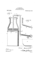
- Figure l is an elevation showing the application of the invention, the upper portlon of the receptacle containing the liquid being in section and the discharge portion of the siphon being also in, section to show the structural details.
- Fig. 2 is a detail view of the discharge mem ber of a modified form of siphon. 1
- the numeral 1 designates a milk jar of ordinary formation adapted to contain milk to be separated. It is to be understood however, that the receptacle may be of any capacity and form.
- a cap 2 is fitted to the upper end of the jar or receptacle 1 and is rovided with an opening to receive-the intake member of the siphon and with an opening1 3 for the admission or outflow of an.
- T e opening 3 may be provided with a closure 4 of any nature to prevent foreign tance and connected at their upper ends by means of a member 7, in the upper side of which is formed an opening 8 for the outflow of air when priming the siphon
- the opening 8 may be closed by means of a flexible sleeve 9 of rubber or like material which-may be rolled back upon itself to uncover the opening 8 when it IS required to provide anoutlet for the air confined in the outflow member dwhenmoving the piston inward therein.
- the siphon may be constructed of any material such as glass, vulcanite or the like, lass being preferred as it admits of the wor ing of thesiphon being:
- the discharge portion 10 of the siphon is strai ht and extends outwardly and iszadapt to receive a piston ILby-IneanS of which the siphon is primed.
- a nozzle 12 is provided near the discharge end of the part 10.
- the outer end of the discharge portion 10 is closed by means of a cap 13 'which is centrally apertured to receive the rod 14 of the piston 11, sald rod bein provided at its outer'end with a bandle or convenience of operation.
- the PIS- ton 11 may be of any COIlStIllCtlOIl,
- the siphon is applled to the receptacle 1 containing the liquid. tobe separated and. is retained in place by suitable means.
- the intake member '5 passes through the opening of the cap 2 and the outflow member 6 is engaged by means of a holder 15 which encircles the re ceptacle 1 and is clamped thereto, said holder having an opening to receive the member 6 which is retained in the adjusted .95
- the holder 15 may be of any construction and consists of a flexible band fitted about the receptacle 1 and having its .end portions overlapped and secured by a suitable fasten ing 17.
- the siphon maybe admsted vertically to bring the lower end of the intake member 5 in proper position with reference to the line of demarcation between the portions of the liquid to. be separated, said siphon being secured in the adjusted position by tightening the set screw 16.
- the opening 8 is closed by unrolling or moving the sleeve 9.
- a suction is created in the, siphon which causes the liquid to pass upward into the intake member and downward. in the outflow member 6, thereby starting the siphon in the .well known manner, the liquid being drawn ofi from the upper portlon of the receptacle 1 by siphonic action in the manner well understood.
- the delivery end of the discharge portion of the siphon may beof any construction and as illustrated in Fig. 2 it is devoid of a discharge nozzle and cap, the piston being entirely withdrawn from the part 10 and the liquid flowing outward from the extremity thereof.
- a vessel 18 may be placed to receive the liquid drawn oif during the separating operation.
- a receptacle adapted to contain a liquid to be separated, a closure the part connecting the upper ends of the inflow and the outflow.
- members having an V opening, an elastic band mounted u on the connecting portion of the siphon an adapted to close the opening formed therein, a
- a holder encircling the receptacle and having its end ortions overlapped and adapted'to be adjusttably connected, said holderhavin g a projecting portion formed with an opening through which the outflow member of thesiphon passes, and a set screw for securing the siphon to the holder.
Landscapes
- Engineering & Computer Science (AREA)
- Mechanical Engineering (AREA)
- General Engineering & Computer Science (AREA)
- Jet Pumps And Other Pumps (AREA)
- Closures For Containers (AREA)
Description
T. YAMASHI TA. SIPHON CREAM SEPARATOR.
APPLICATION FILED APR. 15. 1909.
Patented Aug". 9, 19m.
I Svwentou M .x Z W PATENT OFFICE.
'rn'rsmr YAMASHI EA: or nos, ANGELES, camronnra.
sun-101v cnnansnralm'ron.
Specification of Letters Patent.
Patented Aug. 9, 1910.
Application filed April 15, 1009. Serial 1N0. 490,005.
1 0 all-whom it may concern:
Be it known that I, TETSUJI YAMASHITA, a citizen of Japan, residing at Los Angeles, in the county of Los Angeles and State of California, have invented new and useful Improvements in Siphon Cream-Separators, of which the following is a specification.
The purpose of this invention is to provide novel means for separating liquids by siphonic action bein .adapted most especially for drawing 0 cream from milk.
The. invention contemplates a siphon of peculiar construction and novel means cooperating therewith for adjustably connecting the siphon to the receptacle containing the milk or other liquid to be separated,
whereby the siphon may be properly adjusted to the line or demarcation separating the liquids of diiferentspecific gravities to insure drawing off all the liquid or cream to 'be separated from the remaining portion.
For a full understanding of the invention reference is to be had to the accompanying' drawings and the following description,
it being understood that various changes maybe resorted to Within the scope of the J appended claim without departing from the nature of the invention.
- Referring to the drawings forming a part- .of the specifications, Figure l is an elevation showing the application of the invention, the upper portlon of the receptacle containing the liquid being in section and the discharge portion of the siphon being also in, section to show the structural details. Fig. 2 is a detail view of the discharge mem ber of a modified form of siphon. 1
Corresponding and like parts are referred to in the following description and indicated in all the views in the drawings by the same reference characters.
The numeral 1 designates a milk jar of ordinary formation adapted to contain milk to be separated. It is to be understood however, that the receptacle may be of any capacity and form. A cap 2 is fitted to the upper end of the jar or receptacle 1 and is rovided with an opening to receive-the intake member of the siphon and with an opening1 3 for the admission or outflow of an. T e opening 3 may be provided with a closure 4 of any nature to prevent foreign tance and connected at their upper ends by means of a member 7, in the upper side of which is formed an opening 8 for the outflow of air when priming the siphon The opening 8 may be closed by means of a flexible sleeve 9 of rubber or like material which-may be rolled back upon itself to uncover the opening 8 when it IS required to provide anoutlet for the air confined in the outflow member dwhenmoving the piston inward therein. The siphon may be constructed of any material such as glass, vulcanite or the like, lass being preferred as it admits of the wor ing of thesiphon being:
observed and also any matter tending to lodge therein readily discovered sons to be easily removed. The discharge portion 10 of the siphon is strai ht and extends outwardly and iszadapt to receive a piston ILby-IneanS of which the siphon is primed. A nozzle 12 is provided near the discharge end of the part 10. The outer end of the discharge portion 10 is closed by means of a cap 13 'which is centrally apertured to receive the rod 14 of the piston 11, sald rod bein provided at its outer'end with a bandle or convenience of operation. The PIS- ton 11 may be of any COIlStIllCtlOIl,
In practice, the siphon is applled to the receptacle 1 containing the liquid. tobe separated and. is retained in place by suitable means. As shown, the intake member '5 passes through the opening of the cap 2 and the outflow member 6 is engaged by means of a holder 15 which encircles the re ceptacle 1 and is clamped thereto, said holder having an opening to receive the member 6 which is retained in the adjusted .95
position by means of aset screw 1 6. The holder 15 may be of any construction and consists of a flexible band fitted about the receptacle 1 and having its .end portions overlapped and secured by a suitable fasten ing 17. The siphon maybe admsted vertically to bring the lower end of the intake member 5 in proper position with reference to the line of demarcation between the portions of the liquid to. be separated, said siphon being secured in the adjusted position by tightening the set screw 16.
After the siphon has been properly "adjusted and secured, the intake member 5"- 1s immersed. in the portion of the liquld to be 110 xible or elastic drawn off and the opening 8 'is uncovere by rolling or moving (the e sleeve 9. The piston 11-is moved within the I discharge portion 10, and the air displaced by the piston instead of passing through the siphon and bubbling through the liquid in the receptacle 1, passes out through the opening 8. After the piston has been moved inward to the limit of its stroke, the opening 8 is closed by unrolling or moving the sleeve 9. Upon drawing the'piston outward and past the nozzle 12, a suction is created in the, siphon which causes the liquid to pass upward into the intake member and downward. in the outflow member 6, thereby starting the siphon in the .well known manner, the liquid being drawn ofi from the upper portlon of the receptacle 1 by siphonic action in the manner well understood.
The delivery end of the discharge portion of the siphon may beof any construction and as illustrated in Fig. 2 it is devoid of a discharge nozzle and cap, the piston being entirely withdrawn from the part 10 and the liquid flowing outward from the extremity thereof. A vessel 18 may be placed to receive the liquid drawn oif during the separating operation.
Having thus described the invention, what is claimed is.:-
In combination a receptacle adapted to contain a liquid to be separated, a closure the part connecting the upper ends of the inflow and the outflow. members having an V opening, an elastic band mounted u on the connecting portion of the siphon an adapted to close the opening formed therein, a
piston arranged to operate in the outwardly,
extended portion of the siphon, a holder encircling the receptacle and having its end ortions overlapped and adapted'to be adustably connected, said holderhavin g a projecting portion formed with an opening through which the outflow member of thesiphon passes, and a set screw for securing the siphon to the holder.
In testimony whereof I aflix my signature in presence of two'witnesses.
. TETSUJI YAMASHITA.
'Witnesses;
JOHN W. VAUGHN, A. H. THOMAS.
Priority Applications (1)
| Application Number | Priority Date | Filing Date | Title |
|---|---|---|---|
| US1909490005 US967099A (en) | 1909-04-15 | 1909-04-15 | Siphon cream-separator. |
Applications Claiming Priority (1)
| Application Number | Priority Date | Filing Date | Title |
|---|---|---|---|
| US1909490005 US967099A (en) | 1909-04-15 | 1909-04-15 | Siphon cream-separator. |
Publications (1)
| Publication Number | Publication Date |
|---|---|
| US967099A true US967099A (en) | 1910-08-09 |
Family
ID=3035491
Family Applications (1)
| Application Number | Title | Priority Date | Filing Date |
|---|---|---|---|
| US1909490005 Expired - Lifetime US967099A (en) | 1909-04-15 | 1909-04-15 | Siphon cream-separator. |
Country Status (1)
| Country | Link |
|---|---|
| US (1) | US967099A (en) |
Cited By (1)
| Publication number | Priority date | Publication date | Assignee | Title |
|---|---|---|---|---|
| US3094134A (en) * | 1961-03-02 | 1963-06-18 | Fulbright Lab Inc | Dispersing device |
-
1909
- 1909-04-15 US US1909490005 patent/US967099A/en not_active Expired - Lifetime
Cited By (1)
| Publication number | Priority date | Publication date | Assignee | Title |
|---|---|---|---|---|
| US3094134A (en) * | 1961-03-02 | 1963-06-18 | Fulbright Lab Inc | Dispersing device |
Similar Documents
| Publication | Publication Date | Title |
|---|---|---|
| US1328866A (en) | Cream-separator | |
| US1472896A (en) | Filter | |
| US1488865A (en) | Pouring device for separating milk and cream | |
| US985598A (en) | Liquid-separator. | |
| US1621413A (en) | Filtering device | |
| US2102749A (en) | Dispensing cap | |
| US772707A (en) | Drop-stopper for bottles or the like. | |
| US878389A (en) | Pump. | |
| US133883A (en) | Improvement in bottle-stoppers | |
| US919079A (en) | Siphon-pump. | |
| US1079848A (en) | Cream-remover. | |
| US720471A (en) | Preserving-jar. | |
| US310999A (en) | Atomizer | |
| US1650801A (en) | Container | |
| US1446751A (en) | Ether-can attachment dropper | |
| US539422A (en) | Automatic funnel | |
| US916815A (en) | Bottle casing and closure. | |
| US1518991A (en) | Measuring device | |
| US1332520A (en) | Discharging device for fluids | |
| US983725A (en) | Closure for dispensing vessels. | |
| US990549A (en) | Funnel. | |
| US732689A (en) | Medicine-dropper. | |
| US684231A (en) | Aseptic or hygienic receptacle-cover. | |
| US616336A (en) | Means for racking beer | |
| US903467A (en) | Dropper. |