US9644635B2 - Electric air blower - Google Patents
Electric air blower Download PDFInfo
- Publication number
- US9644635B2 US9644635B2 US14/373,559 US201314373559A US9644635B2 US 9644635 B2 US9644635 B2 US 9644635B2 US 201314373559 A US201314373559 A US 201314373559A US 9644635 B2 US9644635 B2 US 9644635B2
- Authority
- US
- United States
- Prior art keywords
- fan
- suction port
- peripheral surface
- mushroom
- suction
- Prior art date
- Legal status (The legal status is an assumption and is not a legal conclusion. Google has not performed a legal analysis and makes no representation as to the accuracy of the status listed.)
- Active, expires
Links
Images


Classifications
-
- F—MECHANICAL ENGINEERING; LIGHTING; HEATING; WEAPONS; BLASTING
- F04—POSITIVE - DISPLACEMENT MACHINES FOR LIQUIDS; PUMPS FOR LIQUIDS OR ELASTIC FLUIDS
- F04D—NON-POSITIVE-DISPLACEMENT PUMPS
- F04D29/00—Details, component parts, or accessories
- F04D29/08—Sealings
- F04D29/083—Sealings especially adapted for elastic fluid pumps
-
- F—MECHANICAL ENGINEERING; LIGHTING; HEATING; WEAPONS; BLASTING
- F04—POSITIVE - DISPLACEMENT MACHINES FOR LIQUIDS; PUMPS FOR LIQUIDS OR ELASTIC FLUIDS
- F04D—NON-POSITIVE-DISPLACEMENT PUMPS
- F04D29/00—Details, component parts, or accessories
- F04D29/08—Sealings
- F04D29/16—Sealings between pressure and suction sides
- F04D29/161—Sealings between pressure and suction sides especially adapted for elastic fluid pumps
- F04D29/162—Sealings between pressure and suction sides especially adapted for elastic fluid pumps of a centrifugal flow wheel
-
- F—MECHANICAL ENGINEERING; LIGHTING; HEATING; WEAPONS; BLASTING
- F04—POSITIVE - DISPLACEMENT MACHINES FOR LIQUIDS; PUMPS FOR LIQUIDS OR ELASTIC FLUIDS
- F04D—NON-POSITIVE-DISPLACEMENT PUMPS
- F04D29/00—Details, component parts, or accessories
- F04D29/40—Casings; Connections of working fluid
- F04D29/403—Casings; Connections of working fluid especially adapted for elastic fluid pumps
-
- F—MECHANICAL ENGINEERING; LIGHTING; HEATING; WEAPONS; BLASTING
- F04—POSITIVE - DISPLACEMENT MACHINES FOR LIQUIDS; PUMPS FOR LIQUIDS OR ELASTIC FLUIDS
- F04D—NON-POSITIVE-DISPLACEMENT PUMPS
- F04D29/00—Details, component parts, or accessories
- F04D29/40—Casings; Connections of working fluid
- F04D29/42—Casings; Connections of working fluid for radial or helico-centrifugal pumps
- F04D29/4206—Casings; Connections of working fluid for radial or helico-centrifugal pumps especially adapted for elastic fluid pumps
- F04D29/4213—Casings; Connections of working fluid for radial or helico-centrifugal pumps especially adapted for elastic fluid pumps suction ports
-
- F—MECHANICAL ENGINEERING; LIGHTING; HEATING; WEAPONS; BLASTING
- F04—POSITIVE - DISPLACEMENT MACHINES FOR LIQUIDS; PUMPS FOR LIQUIDS OR ELASTIC FLUIDS
- F04D—NON-POSITIVE-DISPLACEMENT PUMPS
- F04D29/00—Details, component parts, or accessories
- F04D29/60—Mounting; Assembling; Disassembling
- F04D29/601—Mounting; Assembling; Disassembling specially adapted for elastic fluid pumps
-
- F—MECHANICAL ENGINEERING; LIGHTING; HEATING; WEAPONS; BLASTING
- F04—POSITIVE - DISPLACEMENT MACHINES FOR LIQUIDS; PUMPS FOR LIQUIDS OR ELASTIC FLUIDS
- F04D—NON-POSITIVE-DISPLACEMENT PUMPS
- F04D29/00—Details, component parts, or accessories
- F04D29/60—Mounting; Assembling; Disassembling
- F04D29/62—Mounting; Assembling; Disassembling of radial or helico-centrifugal pumps
- F04D29/624—Mounting; Assembling; Disassembling of radial or helico-centrifugal pumps especially adapted for elastic fluid pumps
- F04D29/626—Mounting or removal of fans
-
- F—MECHANICAL ENGINEERING; LIGHTING; HEATING; WEAPONS; BLASTING
- F04—POSITIVE - DISPLACEMENT MACHINES FOR LIQUIDS; PUMPS FOR LIQUIDS OR ELASTIC FLUIDS
- F04D—NON-POSITIVE-DISPLACEMENT PUMPS
- F04D17/00—Radial-flow pumps, e.g. centrifugal pumps; Helico-centrifugal pumps
- F04D17/08—Centrifugal pumps
- F04D17/16—Centrifugal pumps for displacing without appreciable compression
-
- F—MECHANICAL ENGINEERING; LIGHTING; HEATING; WEAPONS; BLASTING
- F04—POSITIVE - DISPLACEMENT MACHINES FOR LIQUIDS; PUMPS FOR LIQUIDS OR ELASTIC FLUIDS
- F04D—NON-POSITIVE-DISPLACEMENT PUMPS
- F04D25/00—Pumping installations or systems
- F04D25/02—Units comprising pumps and their driving means
- F04D25/06—Units comprising pumps and their driving means the pump being electrically driven
Definitions
- the present invention relates to electric blowers for use in electric devices such as electric cleaners and hand dryers.
- an electric vacuum cleaner i.e. an electric device, is required to exhibit higher suction power.
- the electric blower includes a motor and a fan unit integrally in one unit.
- the fan unit is airtightly attached to the motor, i.e. hermeticity being held between them.
- the fan unit is composed of air guide 101 , fan case 102 , fan 103 , and fan case spacer 104 .
- Fan 103 includes suction-side shroud 103 a .
- Fan 103 includes suction port 122 in a center portion of suction-side shroud 103 a.
- FIG. 15 is an enlarged cross-sectional view of Z portion shown in FIG. 14 .
- Suction port-side end surface 103 b of suction-side shroud 103 a that fan 103 includes is in contact with the outer-peripheral side surface of bellows 104 a that fan case spacer 104 includes.
- suction port-side end surface 103 b of suction-side shroud 103 a has a very slight clearance of about 0.1 mm or less with the outer-peripheral side surface of bellows 104 a . This configuration secures the airtightness, i.e. the hermeticity, between suction-side shroud 103 a and fan case spacer 104 .
- fan case spacer 104 is fixed to fan case 102 so as to secure the airtightness with fan case 102 .
- Fan case spacer 104 is fixed to fan case 102 , by welding or bonding.
- Patent Literature 1 a technology associated with the conventional electric blower is described.
- the conventional electric blower has had the following problems to be solved.
- the first one is dimensional accuracy of bellows 104 a included in fan case spacer 104 .
- bellows 104 a facing suction-side shroud 103 a has a profile which is difficult to ensure a stable dimensional accuracy of its outer-peripheral side surface.
- the second one is poor concentricity between fan case spacer 104 including bellows 104 a and fan 103 including suction-side shroud 103 a , i.e. a low degree of their positioning accuracy with respective to their common axis.
- fan case spacer 104 is welded to fan case 102 or, alternatively, is bonded and fixed to fan case 102 .
- the concentricity becomes poorer between the outer-peripheral side surface of bellows 104 a and suction port-side end surface 103 b of suction-side shroud 103 a.
- the third one lies in circularity of bellows 104 a . That is, when the electric blower is operated, the motor section thereof generates heat. When fan case 102 is made of metal, the generated heat is conducted to fan case spacer 104 via fan case 102 , i.e., the metal material. The thus-conducted heat raises the temperature of fan case spacer 104 . Temperature-raised fan case spacer 104 sometimes deforms due to its thermal expansion. Such deformation of fan case spacer 104 can deteriorate the circularity of bellows 104 a that forms a part of fan case spacer 104 .
- the thus-deteriorated dimensional accuracy results in insufficient airtightness between suction port-side end surface 103 b of suction-side shroud 103 a included in fan 103 and the outer-peripheral side surface of bellows 104 a included fan case spacer 104 .
- the insufficient airtightness sometimes causes a reverse flow of air discharged from the outer periphery of fan 103 , through a gap between fan case 102 and an upper portion of suction-side shroud 103 a included in fan 103 .
- Such a reverse-flow phenomenon leads to an air-leakage into a suction-port portion of fan 103 , i.e. suction port 122 .
- this interferes with the drop in vacuum pressure at the suction-port portion of fan 103 , resulting in a decrease in the output of the electric blower.
- the decrease in the output leads to a reduction in the suction power in an electric cleaner.
- fan case spacer 104 is press-fitted into a bracket of the electric blower. In this way, fan case 102 is fixed to the bracket of the electric blower. Fan case 102 is press-fitted into the bracket, in a state that suction port-side end surface 103 b of suction-side shroud 103 a is in contact with the outer peripheral side surface of bellows 104 a included in fan case spacer 104 .
- Fan case spacer 104 is then very large in size.
- Fan case spacer 104 is formed as a molded article.
- Patent Literature 1 Japanese Patent Unexamined Publication No. H06-323297
- An electric blower includes a field magnet, an armature, a pair of brushes, a fan, an air guide, a fan case, and a fan seal.
- the field magnet is held by a bracket.
- the armature includes a pair of bearings at both ends of an armature shaft, and the armature is supported by the pair of the bearings.
- the pair of the brushes is disposed in the bracket.
- the fan is disposed on the output side of the armature shaft.
- the fan includes a suction-side shroud and a suction port at a center portion of the suction-side shroud.
- the air guide is disposed on the exhaust side of the fan.
- the fan case covers both the fan and the air guide.
- the fan case includes an opening part at a location facing the suction port.
- the fan seal is disposed between the inner wall surface of the fan case and the suction port-side end surface of the suction-side shroud.
- an inner peripheral surface refers to a surface which faces the inner wall surface
- an outer peripheral surface refers to a surface which faces the suction port-side end surface.
- the opening part includes a plurality of mushroom-shaped anchors.
- the fan seal includes holding parts which fit onto the mushroom-shaped anchors.
- the fan seal is press-fitted onto the fan case; the fan seal is fixed to the fan case.
- FIG. 1 is a partially-cutaway side-elevational view of an electric blower according to a first embodiment of the present invention.
- FIG. 2 is an enlarged view of a principal part of the electric blower.
- FIG. 3 is a view illustrating assembling of the principal part of the electric blower shown in FIG. 2 .
- FIG. 4 is an elevational view of a principal part of a fan case which the electric blower includes.
- FIG. 5 is an enlarged view of a principal part of the fan case when viewed from the direction indicated by arrow A shown in FIG. 3 .
- FIG. 6 is an elevational view of a fan seal which the electric blower includes.
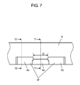
- FIG. 7 is an enlarged view of a principal part of the fan seal when viewed from the direction indicated by arrow B shown in FIG. 3 .
- FIG. 8 is a view illustrating steps of assembling the principal parts of the fan case and the fan seal which both are included in the electric blower.
- FIG. 9 is a view illustrating the steps of assembling the principal parts of the fan case and the fan seal which both are included in the electric blower.
- FIG. 10 is a view illustrating the steps of assembling the principal parts of the fan case and the fan seal which both are included in the electric blower.
- FIG. 11 is a cross-sectional view of a fan seal included in an electric blower according to a second embodiment of the present invention, taken along line 11 - 11 of FIG. 7 .
- FIG. 12 is a cross-sectional view of the fan seal included in the electric blower, taken along line 12 - 12 of FIG. 7 .
- FIG. 13 is a view illustrating steps of assembling principal parts of a fan case and the fan seal which both are included in the electric blower.
- FIG. 14 is a partially-cutaway side-elevational view of a conventional electric blower.
- FIG. 15 is an enlarged view of a principal part of the conventional electric blower.
- An electric blower according to an embodiment of the present invention takes a configuration to be described later, which thereby solves the to-be-improved problems of conventional electric blowers.
- the thrust direction is the axial direction of an armature shaft which rotates a fan.
- the fan includes a suction port to be described later.
- the center of an opening part to be described later which is included in a fan case facing the suction port.
- a guide part which forms the opening part is extended along the axial direction.
- the radial direction is a direction perpendicularly intersecting the thrust direction.
- the mushroom-shaped anchor is a locking part having a predetermined width, which forms a flange-shaped wall of the fan case.
- the flange-shaped locking part has a projection part at the end portion thereof. The projection part protrudes toward both directions that perpendicularly intersect the direction in which the locking parts extend.
- the electric blower according to the embodiment of the invention includes a field magnet, an armature, a pair of brushes, the fan, an air guide, the fan case, and a fan seal.
- the field magnet is held by a bracket.
- the armature includes a pair of bearings at both ends of the armature shaft, with the armature being supported by the pair of the bearings.
- the pair of the brushes is disposed in the bracket.
- the fan is disposed on the output side of the armature shaft.
- the fan includes a suction-side shroud and a suction port at a center portion of the suction-side shroud.
- the air guide is disposed on the exhaust side of the fan.
- the fan case covers both the fan and the air guide.
- the fan case includes the opening part at a location facing the suction port.
- the fan seal is disposed between the inner wall surface of the fan case and the suction port-side end surface of the suction-side shroud.
- an inner peripheral surface refers to a surface which faces the inner wall surface
- an outer peripheral surface refers to a surface which faces the suction port-side end surface.
- the opening part includes a plurality of the mushroom-shaped anchors.
- the fan seal includes holding parts which fit respectively onto the mushroom-shaped anchors.
- the fan seal coincident in shape with the fan case is press-fitted onto the fan case that includes the mushroom-shaped anchors.
- the holding parts of the fan seal are press-fitted onto the mushroom-shaped anchors of the fan case.
- the mushroom-shaped anchors are fitted into the holding parts. In this way, the fan seal is fixed to the fan case.
- the opening part includes a suction port-side opening end, an outer-side opening end, and the guide part.
- the suction port-side opening end communicates with the suction port.
- the outer-side opening end communicates with the outside of the fan case.
- the guide part communicates between the suction port-side opening end and the outer-side opening end.
- the guide part includes the plurality of the mushroom-shaped anchors at the periphery of the suction port-side opening end, in the thrust direction in which the guide part extends.
- the fan seal is composed of an elastic material such as rubber or resin, the fan seal is capable of taking a profile which can fit in shape with the opening part of the fan case.
- the inner peripheral surface of the fan seal takes a profile which fits in shape with the outer periphery of the guide part, i.e. the inner wall surface of the fan case.
- the outer peripheral surface of the fan seal i.e. the back side of the inner peripheral surface of the fan seal, also takes a profile which fits in shape with the inner wall surface of the fan case.
- the profile of the outer peripheral surface of the fan seal is stabilized; therefore, the outer peripheral surface becomes in contact with the suction port-side end surface of the suction-side shroud.
- the outer peripheral surface of the fan seal, which faces the suction port-side end surface of the suction-side shroud is secured to have a stable dimensional accuracy in terms of concentricity, circularity, and the like.
- the holding parts may be formed in the following shape. That is, the holding parts each have a bump shape, on the inner peripheral surface, which is capable of holding the respective mushroom-shaped anchor.
- the bumps are formed on the inner peripheral surface of the fan seal, with the bumps having the thickness larger than that of the fan case, especially that of the wall configuring the guide part of the fan case. That is, each of the bumps is formed such that an end portion of the guide part protrudes from the inner wall surface side toward the shaft center side, in the radial direction.
- the bumps are operative to retain the holding strength of the fan seal in the radial direction, when the fan seal is held by the fan case, especially by the guide part thereof.
- each of the holding parts includes a pair of the bumps.
- the holding part includes an inclined part, in between the bumps of the pair, the inner peripheral surface of which is inclined from the inner peripheral surface side toward the outer peripheral surface side.
- Each of the mushroom-shaped anchors is inclined along the respective inclined part.
- the end portion of the mushroom-shaped anchor is bent at the angle along the inclined part.
- the end portion of the mushroom-shaped anchor is expanded such that the fan case becomes in a state of being crimped and fixed to the fan seal.
- the fan seal is press-fitted along the inner wall surface of the fan case.
- the press-fitted fan seal is fixed to the fan case, which can secure the stable airtightness. This increases the output of the electric blower.
- the seal member i.e. the fan seal
- the seal member can be made smaller in size. It is possible to adopt the simplified method of fixation in which the fan seal is press-fitted along the inner wall surface of the fan case. Consequently, the cheap sealing-configuration is available for the electric blower.
- FIG. 1 is a partially-cutaway side-elevational view of an electric blower according to an embodiment of the present invention.
- FIG. 2 is an enlarged view of a principal part of the electric blower.
- FIG. 3 is a view illustrating assembling of the principal part of the electric blower shown in FIG. 2 .
- field magnet 5 is fixed to bracket 8 .
- armature 7 is disposed which is supported by a pair of bearings 6 .
- bracket 8 a pair of brushes 9 is attached.
- a control current is supplied, via the pair of brushes 9 , to commutator 10 that armature 7 includes.
- armature 7 rotates.
- fan 3 is attached in a state of being airtight, i.e. hermetic. When armature 7 rotates, fan 3 also rotates at high speed.
- Fan 3 includes suction port 22 in a center portion of the fan.
- Fan case 2 includes opening part 13 at a location facing suction port 22 . When fan 3 rotates, air flows in from suction port 22 via opening part 13 .
- the thus-flow-in air is discharged from an inlet part of fan 3 toward the outer peripheral direction.
- the thus-discharged air flows through air guide 1 into a motor unit.
- FIG. 2 is an enlarged view of Y portion shown in FIG. 1 .
- Fan seal 4 is disposed between inner wall surface 2 a of fan case 2 and suction port-side end surface 3 b of suction-side shroud 3 a that fan 3 includes.
- Fan seal 4 is aimed at keeping the airtightness, i.e. the hermeticity.
- Fan seal 4 is accommodated in the inside of fan case 2 .
- a conventional electric blower is formed such that fan case spacer 104 to keep airtightness is disposed in the outside of fan case 102 .
- Fan seal 4 includes outer-peripheral flat part 4 a on the outer-side opening end 13 b side of fan case 2 .
- outer-peripheral flat part 4 a is held by a press-fitting fixture.
- Outer-peripheral flat part 4 a is applied with a load by the press-fitting fixture.
- FIG. 3 is a view illustrating a state in which fan seal 4 is press-fitted onto fan case 2 .
- arrow F indicates the direction in which fan seal 4 is press-fitted.
- fan case 2 includes opening part 13 .
- Opening part 13 includes suction port-side opening end 13 a on one side.
- Opening part 13 includes outer-side opening end 13 b on the other side.
- Opening part 13 includes guide part 13 c that communicates between suction port-side opening end 13 a and outer-side opening end 13 b .
- mushroom-shaped anchors 2 b are formed at the periphery of suction port-side opening end 13 a of guide part 13 c .
- bumps 4 f serving as holding parts 4 b are disposed on inner peripheral surface 4 d of fan seal 4 .
- Bumps 4 f serving as holding parts 4 b are each configured to protrude from the inner wall surface 2 a side of fan case 2 toward the inner-diametrical surface 2 c side thereof.
- This configuration is especially effective when the following dimensional relation is satisfied between bumps 4 f and the thickness of the wall that forms guide part 13 c . That is, let t1 be the dimension of protrusion of bumps 4 f from inner peripheral surface 4 d , i.e. the thickness of bumps 4 f , and let t2 be the thickness of the guide part 13 c . This leads to the relation that t1 is larger than t2.
- bumps 4 f are formed on inner peripheral surface 4 d of fan seal 4 , with the thickness of the bumps being larger than that of fan case 2 , especially that of the wall configuring guide part 13 c . That is, bumps 4 f are configured such that the end portions of the bumps protrude away from guide part 13 c in the radial direction, from the inner wall surface 2 a side to the axial direction side in the radial direction.
- This configuration allows a proof stress thereof against stresses in the radial direction which are caused during the rotation of fan 3 .
- FIG. 4 is an elevational view of a principal part of the fan case that is included in the electric blower according to the embodiment of the present invention.
- FIG. 5 is an enlarged view of a principal part of the fan case when viewed from the direction indicated by arrow A shown in FIG. 3 .
- FIG. 4 is the view of guide part 13 c , which forms opening part 13 , of fan case 2 when viewed from the thrust direction (from the lower side of FIG. 1 ).
- FIG. 5 is the view of guide part 13 c of fan case 2 shown in FIG. 3 , when viewed from the direction indicated by arrow A.
- mushroom-shaped anchors 2 b are disposed at six locations, one for each.
- the number of mushroom-shaped anchors 2 b is preferably three to eight. If the number of mushroom-shaped anchors 2 b is less than three, it results in a reduced strength of holding fan seal 4 . Therefore, during the rotation of fan 3 , the proof stress of the configuration is insufficient against the stresses caused by the rotation of fan 3 . Consequently, there is a risk that fan seal 4 will be dislodged during the rotation of fan 3 . Conversely, if the number of mushroom-shaped anchors 2 b is more than eight, it results in a deteriorated circularity of guide part 13 c .
- the thus-deteriorated circularity of guide part 13 c reduces the circularity of opening part 13 as well.
- the thus-reduced circularity of opening part 13 decreases the airtightness between fan 3 and fan seal 4 .
- the output of the electric blower drops.
- FIG. 6 is an elevational view of the fan seal that is included in the electric blower according to the embodiment of the present invention.
- FIG. 7 is an enlarged view of a principal part of the fan seal when viewed from the direction indicated by arrow B shown in FIG. 3 .
- FIG. 6 is the view of fan seal 4 , when viewed from the thrust direction (from the lower side of FIG. 1 ).
- FIG. 7 is the view of holding part 4 b included in fan seal 4 shown in FIG. 3 , when viewed from the direction indicated by arrow B.
- holding parts 4 b are disposed.
- Each of holding parts 4 b includes a pair of bumps 4 f .
- the pair of bumps 4 f is coincident in shape with space parts 2 d that are located on both sides of each of mushroom-shaped anchors 2 b shown in FIG. 5 .
- holding parts 4 b are disposed at six locations, one for each. That is, fan seal 4 is provided with six holding parts 4 b ; therefore, a total 12 of bumps 4 f are disposed.
- Distance D between bumps 4 f of the pair shown in FIG. 7 is about 0.5 mm smaller than width C of fluke part 2 e of each of mushroom-shaped anchors 2 b shown in FIG. 5 .
- Mushroom-shaped anchor 2 b shown in FIG. 5 has shank part 2 f , serving as anchor's root portion, width E of which is about 0.5 mm smaller than distance D between bumps 4 f of the pair shown in FIG. 7 .
- fluke part 2 e as referred herein is the projection part that protrudes toward both directions perpendicularly intersecting the direction in which the locking parts extend, in mushroom-shaped anchor 2 b according to the embodiment of the present invention.
- width C of fluke part 2 e refers to the width across the projection part in the directions in which the projection part protrudes. In the embodiment of the present invention, width C is 3.5 mm, while distance D is 3.0 mm.
- Shank part 2 f as referred herein is the portion that connects between the body of fan case 2 and the end portion of the locking part which extends from the body, in mushroom-shaped anchor 2 b according to the embodiment of the present invention.
- width E is 2.5 mm.
- Fan case 2 and fan seal 4 both having the configurations described above, are combined with each other. Referring to FIGS. 8 to 10 , steps of combining fan case 2 and fan seal 4 will be described.
- fan seal 4 having holding parts 4 b each of which is formed of the pair of bumps 4 f is press-fitted onto fan case 2 having mushroom-shaped anchors 2 b , in the direction indicated by arrow F.
- each of the pairs of bumps 4 f is press-fitted onto respective one of mushroom-shaped anchors 2 b .
- distance D between bumps 4 f of the pair is about 0.5 mm smaller than width C across fluke part 2 e of each of mushroom-shaped anchors 2 b . With this dimension, the pair of bumps 4 f is allowed to be press-fitted onto mushroom-shaped anchor 2 b included in fan case 2 .
- the pair of bumps 4 f is press-fitted into recesses beyond fluke part 2 e of mushroom-shaped anchor 2 b .
- width E of shank part 2 f is about 0.5 mm smaller than distance D between bumps 4 f of the pair. With this dimension, shank part 2 f is allowed to be fitted into bumps 4 f of the pair; shank part 2 f is held by bumps 4 f of the pair.
- Thus-fitted fan seal 4 is formed of a material, such as PP (polypropylene) and PET (polyethylene terephthalate), which has a property that it shrinks upon heating.
- PP polypropylene
- PET polyethylene terephthalate
- the configuration will provide the following effects. That is, upon operation of the electric blower, the temperature of the inside of the electric blower rises. The temperature rise of the inside of the electric blower causes fan seal 4 to shrink due to the heat. When fan seal 4 shrinks due to the heat, it causes fan seal 4 to follow the shape of fan case 2 . In other words, inner peripheral surface 4 d of fan seal 4 coincides in shape with the inner wall surface of fan case 2 . Accordingly, this allows more stable dimensional accuracy of both inner peripheral surface 4 d of fan seal 4 and the inner wall surface of fan case 2 .
- the heat shrinkage also provides the effect of increasing the holding strength by holding parts 4 b that fan seal 4 includes.
- the electric blower includes field magnet 5 , armature 7 , the pair of brushes 9 , fan 3 , air guide 1 , fan case 2 , and fan seal 4 .
- Field magnet 5 is held by bracket 8 .
- Armature 7 includes the pair of bearings 6 disposed at both ends of armature shaft 21 , and is supported by the pair of bearings 6 .
- the pair of brushes 9 is disposed in bracket 8 .
- Fan 3 is disposed on the output side of armature shaft 21 .
- Fan 3 includes suction-side shroud 3 a and suction port 22 disposed at the center portion of suction-side shroud 3 a .
- Air guide 1 is disposed on the exhaust side of fan 3 .
- Fan case 2 covers both fan 3 and air guide 1 .
- Fan case 2 includes opening part 13 at the location facing suction port 22 .
- Fan seal 4 is disposed between inner wall surface 2 a of fan case 2 and suction port-side end surface 3 b of suction-side shroud 3 a .
- inner peripheral surface 4 d refers to the surface that faces inner wall surface 2 a .
- outer peripheral surface 4 e refers to the surface that faces suction port-side end surface 3 b .
- Opening part 13 includes the plurality of mushroom-shaped anchors 2 b .
- Fan seal 4 includes holding parts 4 b that fit respectively into mushroom-shaped anchors 2 b.
- fan seal 4 coincident in shape with fan case 2 is press-fitted onto fan case 2 that includes mushroom-shaped anchors 2 b .
- holding parts 4 b that fan seal 4 includes are press-fitted respectively onto mushroom-shaped anchors 2 b that fan case 2 includes.
- mushroom-shaped anchors 2 b are fitted respectively into holding parts 4 b .
- fan seal 4 is fixed to fan case 2 .
- opening part 13 includes suction port-side opening end 13 a , outer-side opening end 13 b , and guide part 13 c.
- Suction port-side opening end 13 a communicates with suction port 22 .
- Outer-side opening end 13 b communicates with the outside of fan case 2 .
- Guide part 13 c communicates between suction port-side opening end 13 a and outer-side opening end 13 b .
- Guide part 13 c includes the plurality of mushroom-shaped anchors 2 b at the periphery of suction port-side opening end 13 a , in the thrust direction in which guide part 13 c extends.
- the plurality of mushroom-shaped anchors 2 b are formed, in particular, along the end portion of suction port-side opening end 13 a that fan case 2 includes.
- the location where the plurality of mushroom-shaped anchors 2 b is formed is not limited to the end portion of suction port-side opening end 13 a .
- Other locations in the vicinity of suction port-side opening end 13 a may also be available for the position where the plurality of mushroom-shaped anchors 2 b is formed, as long as the airtightness between fan case 2 and fan seal 4 , to be described later, can be retained.
- fan seal 4 can take a profile which fits in shape with opening part 13 of fan case 2 .
- inner peripheral surface 4 d of fan seal 4 takes the profile that follows the outer periphery of guide part 13 c , i.e. inner wall surface 2 a of fan case 2 .
- Outer peripheral surface 4 e of fan seal 4 i.e. the back side of inner peripheral surface 4 d of fan seal 4 , also takes a profile that follows inner wall surface 2 a of fan case 2 .
- the shape of outer peripheral surface 4 e of fan seal 4 becomes stable. Therefore, the outer peripheral surface becomes in contact with suction port-side end surface 3 b of suction-side shroud 3 a .
- outer peripheral surface 4 e of fan seal 4 which faces suction port-side end surface 3 b of suction-side shroud 3 a , is secured to have a stable dimensional accuracy in terms of concentricity, circularity, and the like.
- each of holding parts 4 b has the following shape. That is, holding part 4 b is of a bump shape, on inner peripheral surface 4 d , which is capable of holding respective mushroom-shaped anchor 2 b .
- bump 4 f is caused to protrude toward the center of opening part 13 .
- bumps 4 f are formed on inner peripheral surface 4 d of fan seal 4 , with the thickness of the bumps being larger than that of fan case 2 , especially that of the wall configuring guide part 13 c . That is, bumps 4 f are configured such that the end portions of the bumps protrude away from guide part 13 c in the radial direction, from the inner wall surface 2 a side to the axial direction side.
- bumps 4 f are operative to retain the holding strength of fan seal 4 in the radial direction, when the fan seal is held by fan case 2 , especially by guide part 13 c.
- FIG. 11 is a cross-sectional view of a fan seal included in an electric blower according to the second embodiment of the present invention, taken along line 11 - 11 of FIG. 7 .
- FIG. 12 is a cross-sectional view of the fan seal included in the electric blower, taken along line 12 - 12 of FIG. 7 .
- FIG. 13 is a view illustrating the order of steps of assembling principal parts of a fan case and the fan seal which both are included in the electric blower.
- holding parts 4 b may have the following shape. That is, each of holding parts 4 b is formed of a pair of bumps 4 f . As shown in FIG. 11 , in between bumps 4 f of the pair, holding part 4 b includes inclined parts 4 c , inner peripheral surface 4 d of which is inclined from the inner peripheral surface 4 d side toward the outer peripheral surface 4 e side.
- fan seal 4 is press-fitted onto fan case 2 .
- mushroom-shaped anchors 2 b are bent at an angle along the inclined surfaces of inclined parts 4 c that fan seal 4 includes. That is, mushroom-shaped anchors 2 b are inclined along inclined parts 4 c.
- each of mushroom-shaped anchors 2 b is bent at the angle along inclined part 4 c .
- the end portion of mushroom-shaped anchor 2 b includes the projection part that protrudes toward both directions perpendicularly intersecting the direction in which mushroom-shaped anchor 2 b extends from the body of fan case 2 . Since this projection part engages with the pair of bumps 4 f , fan case 2 becomes in a state of being crimped and fixed to fan seal 4 .
- inner peripheral surface 4 d of fan seal 4 takes a profile that follows the outer periphery of guide part 13 c , i.e. inner wall surface 2 a of fan case 2 , with both inclined parts 4 c and the end portions of mushroom-shaped anchors 2 b being as principal parts.
- Outer peripheral surface 4 e of fan seal 4 i.e. the back side of inner peripheral surface 4 d of fan seal 4 , also takes a profile that follows inner wall surface 2 a of fan case 2 .
- the shape of outer peripheral surface 4 e of fan seal 4 becomes more stable than that described in the first embodiment.
- outer peripheral surface 4 e of fan seal 4 either comes in contact with or faces suction port-side end surface 3 b of suction-side shroud 3 a , which allows the outer peripheral surface 4 e to be secured to have a stable dimensional accuracy in terms of concentricity, circularity, and the like.
- fan seal 4 is held by fan case 2 , the strength in the radial and thrust directions becomes further improved.
- fan seal 4 is crimped and fixed to fan case 2 in both the thrust and radial directions.
- the electric blower according to the second embodiment of the present invention is secured to have the stable airtightness, which allows the increased output of the electric blower.
- the electric blower according to the embodiments of the present invention is such that the inner peripheral surface of its fan seal is press-fitted so as to be directly in contact with the inner wall surface of its fan case.
- the mushroom-shaped anchors engage with the respective holding parts.
- Fan case 2 becomes in the state of being crimped and fixed to fan seal 4 . Accordingly, since the press-fitted fan seal is fixed to the fan case, the electric blower is secured to have the stable airtightness. Therefore, the output of the electric blower is increased.
- the end portions of the mushroom-shaped anchors that the fan case includes are bent along the inclined parts that fan seal 4 includes. This configuration allows the further increased airtightness.
- the sealing material can be made smaller in size than that of conventional electric blowers. Furthermore, the electric blower according to the embodiments of the invention eliminates the need for the fixation by bonding or welding, which allows the simplified configuration for the fixation. Consequently, the cheap sealing-configuration is allowed for the electric blower according to the embodiments of the present invention.
- the electric blower according to the present invention is capable of adopting the cheap sealing-configuration which allows the stable airtightness between the fan and the fan case.
- the electric blower according to the invention is applicable to electric devices such as electric cleaners and hand dryers.
Landscapes
- Engineering & Computer Science (AREA)
- Mechanical Engineering (AREA)
- General Engineering & Computer Science (AREA)
- Structures Of Non-Positive Displacement Pumps (AREA)
Abstract
Description
-
- 1 air guide
- 2 fan case
- 2 a inner wall surface
- 2 b mushroom-shaped anchor
- 2 c inner-diametrical surface
- 2 d space part
- 2 e fluke part
- 2 f shank part
- 3 fan
- 3 a suction-side shroud
- 3 b suction port-side end surface
- 4 fan seal
- 4 a outer-peripheral flat part
- 4 b holding part
- 4 c inclined part
- 4 d inner peripheral surface
- 4 e outer peripheral surface
- 4 f bump
- 5 field magnet
- 6 bearing
- 7 armature
- 8 bracket
- 9 brush
- 10 commutator
- 13 opening part
- 13 a suction port-side opening end
- 13 b outer-side opening end
- 13 c guide part
- 21 armature shaft
- 22 suction port
Claims (12)
Applications Claiming Priority (3)
| Application Number | Priority Date | Filing Date | Title |
|---|---|---|---|
| JP2012063016 | 2012-03-21 | ||
| JP2012-063016 | 2012-03-21 | ||
| PCT/JP2013/001286 WO2013140723A1 (en) | 2012-03-21 | 2013-03-04 | Electric air blower |
Publications (2)
| Publication Number | Publication Date |
|---|---|
| US20140369870A1 US20140369870A1 (en) | 2014-12-18 |
| US9644635B2 true US9644635B2 (en) | 2017-05-09 |
Family
ID=49222207
Family Applications (1)
| Application Number | Title | Priority Date | Filing Date |
|---|---|---|---|
| US14/373,559 Active 2034-01-24 US9644635B2 (en) | 2012-03-21 | 2013-03-04 | Electric air blower |
Country Status (5)
| Country | Link |
|---|---|
| US (1) | US9644635B2 (en) |
| EP (1) | EP2829736B1 (en) |
| JP (1) | JP6074600B2 (en) |
| CN (1) | CN104204539B (en) |
| WO (1) | WO2013140723A1 (en) |
Cited By (1)
| Publication number | Priority date | Publication date | Assignee | Title |
|---|---|---|---|---|
| US20180064302A1 (en) * | 2015-03-12 | 2018-03-08 | Lg Electronics Inc. | Vacuum suctioning unit |
Families Citing this family (3)
| Publication number | Priority date | Publication date | Assignee | Title |
|---|---|---|---|---|
| JP6450928B2 (en) * | 2014-10-17 | 2019-01-16 | パナソニックIpマネジメント株式会社 | Electric blower and electric vacuum cleaner using the same |
| US20170259929A1 (en) * | 2016-03-10 | 2017-09-14 | General Electric Company | Method and system for mounting an aircraft engine |
| JP2018096312A (en) * | 2016-12-15 | 2018-06-21 | ダイキン工業株式会社 | Blower, and refrigeration device with blower |
Citations (30)
| Publication number | Priority date | Publication date | Assignee | Title |
|---|---|---|---|---|
| US1525884A (en) * | 1921-12-01 | 1925-02-10 | Plummer Henry Guion | Centrifugal pump |
| US4718805A (en) | 1985-09-13 | 1988-01-12 | Becker Floyd W | Pipe handling apparatus |
| US4767285A (en) * | 1986-04-14 | 1988-08-30 | Hitachi, Ltd. | Electric blower |
| US5110266A (en) * | 1989-03-01 | 1992-05-05 | Hitachi, Ltd. | Electric blower having improved return passage for discharged air flow |
| CA2056483A1 (en) | 1990-12-04 | 1992-06-05 | Ivor N. Paech | Rod handler apparatus |
| JPH06323297A (en) | 1993-05-13 | 1994-11-22 | Matsushita Electric Ind Co Ltd | Electric blower |
| JPH08326698A (en) | 1995-05-31 | 1996-12-10 | Hitachi Ltd | Electric blower |
| JPH0979189A (en) | 1995-09-14 | 1997-03-25 | Matsushita Electric Ind Co Ltd | Electric blower |
| JPH09317693A (en) | 1996-05-31 | 1997-12-09 | Sanyo Electric Co Ltd | Electric blower |
| WO1998055728A1 (en) | 1997-06-06 | 1998-12-10 | Universal Drilling Systems (Aust) Pty. Limited | Apparatus for moving drill rods |
| JPH11201093A (en) | 1998-10-28 | 1999-07-27 | Hitachi Ltd | Electric blower |
| US5954476A (en) * | 1997-08-12 | 1999-09-21 | Fasco Industries, Inc. | Snap-fit blower housing assembly and seal method |
| EP1045177A1 (en) | 1999-04-13 | 2000-10-18 | Iveco Magirus Ag | Centrifugal pump |
| JP2000303991A (en) | 1999-04-22 | 2000-10-31 | Mitsubishi Electric Corp | Electric blower |
| WO2000065193A1 (en) | 1999-04-28 | 2000-11-02 | Boart Longyear Pty. Ltd. | Drill rod handling device |
| US6439843B1 (en) * | 2000-11-16 | 2002-08-27 | Ametek, Inc. | Motor/fan assembly having a radial diffuser bypass |
| US6527509B2 (en) * | 1999-04-26 | 2003-03-04 | Hitachi, Ltd. | Turbo machines |
| JP2003083291A (en) | 2001-09-05 | 2003-03-19 | Toshiba Tec Corp | Electric blower and vacuum cleaner |
| US20050269133A1 (en) | 2004-06-04 | 2005-12-08 | Graham Little | Handling apparatus |
| JP2007040110A (en) | 2005-08-01 | 2007-02-15 | Calsonic Kansei Corp | Fan shroud structure of heat exchanger |
| US7244099B2 (en) * | 2003-05-01 | 2007-07-17 | Daikin Industries, Ltd. | Multi-vane centrifugal fan |
| US7281908B2 (en) * | 2001-12-21 | 2007-10-16 | Matsushita Electric Indutrial Co., Ltd. | Electrically powered blower with improved heat dissipation |
| AU2007236557A1 (en) | 2006-04-11 | 2007-10-18 | Boart Longyear Manufacturing And Distribution Inc. | Drill rod handler |
| CN101179217A (en) | 2006-11-10 | 2008-05-14 | 日立空调·家用电器株式会社 | Brush device of commutator motor and electric vacuum cleaner |
| US20090297326A1 (en) | 2008-06-03 | 2009-12-03 | Longyear Tm, Inc. | Spring-loaded rod handling device |
| WO2010141585A2 (en) | 2009-06-03 | 2010-12-09 | Longyear Tm, Inc. | Drill rod handler |
| CN201925193U (en) | 2011-01-12 | 2011-08-10 | 刘金怀 | Electric blower |
| CN102242723A (en) | 2010-05-12 | 2011-11-16 | 松下电器产业株式会社 | Electric blower and electric dust collector using the electric blower |
| JP2011247098A (en) | 2010-05-24 | 2011-12-08 | Sanyo Electric Co Ltd | Electric blower |
| US8317496B2 (en) * | 2010-03-03 | 2012-11-27 | Ametek, Inc. | Motor-fan assembly having a tapered fan with a concave underside |
Family Cites Families (6)
| Publication number | Priority date | Publication date | Assignee | Title |
|---|---|---|---|---|
| JPS59177797U (en) * | 1983-05-10 | 1984-11-28 | 株式会社荏原製作所 | Impeller for blower |
| JPH0411297U (en) * | 1990-05-21 | 1992-01-30 | ||
| JP3472893B2 (en) * | 1995-09-08 | 2003-12-02 | 三菱電機株式会社 | Electric blower |
| DE19855905B4 (en) * | 1998-12-03 | 2013-02-21 | BSH Bosch und Siemens Hausgeräte GmbH | blower assembly |
| JP2003083294A (en) * | 2001-09-05 | 2003-03-19 | Toshiba Tec Corp | Electric blower and vacuum cleaner |
| JP2007113402A (en) * | 2005-10-18 | 2007-05-10 | Matsushita Electric Ind Co Ltd | Electric blower |
-
2013
- 2013-03-04 CN CN201380015094.3A patent/CN104204539B/en active Active
- 2013-03-04 WO PCT/JP2013/001286 patent/WO2013140723A1/en not_active Ceased
- 2013-03-04 JP JP2014505993A patent/JP6074600B2/en active Active
- 2013-03-04 EP EP13764541.2A patent/EP2829736B1/en active Active
- 2013-03-04 US US14/373,559 patent/US9644635B2/en active Active
Patent Citations (34)
| Publication number | Priority date | Publication date | Assignee | Title |
|---|---|---|---|---|
| US1525884A (en) * | 1921-12-01 | 1925-02-10 | Plummer Henry Guion | Centrifugal pump |
| US4718805A (en) | 1985-09-13 | 1988-01-12 | Becker Floyd W | Pipe handling apparatus |
| US4767285A (en) * | 1986-04-14 | 1988-08-30 | Hitachi, Ltd. | Electric blower |
| US5110266A (en) * | 1989-03-01 | 1992-05-05 | Hitachi, Ltd. | Electric blower having improved return passage for discharged air flow |
| CA2056483A1 (en) | 1990-12-04 | 1992-06-05 | Ivor N. Paech | Rod handler apparatus |
| US5183366A (en) | 1990-12-04 | 1993-02-02 | Longyear Company | Rod handler apparatus |
| JPH06323297A (en) | 1993-05-13 | 1994-11-22 | Matsushita Electric Ind Co Ltd | Electric blower |
| JPH08326698A (en) | 1995-05-31 | 1996-12-10 | Hitachi Ltd | Electric blower |
| JPH0979189A (en) | 1995-09-14 | 1997-03-25 | Matsushita Electric Ind Co Ltd | Electric blower |
| JPH09317693A (en) | 1996-05-31 | 1997-12-09 | Sanyo Electric Co Ltd | Electric blower |
| WO1998055728A1 (en) | 1997-06-06 | 1998-12-10 | Universal Drilling Systems (Aust) Pty. Limited | Apparatus for moving drill rods |
| US5954476A (en) * | 1997-08-12 | 1999-09-21 | Fasco Industries, Inc. | Snap-fit blower housing assembly and seal method |
| JPH11201093A (en) | 1998-10-28 | 1999-07-27 | Hitachi Ltd | Electric blower |
| EP1045177A1 (en) | 1999-04-13 | 2000-10-18 | Iveco Magirus Ag | Centrifugal pump |
| JP2000297774A (en) | 1999-04-13 | 2000-10-24 | Iveco Magirus Ag | Volute pump |
| JP2000303991A (en) | 1999-04-22 | 2000-10-31 | Mitsubishi Electric Corp | Electric blower |
| US6527509B2 (en) * | 1999-04-26 | 2003-03-04 | Hitachi, Ltd. | Turbo machines |
| WO2000065193A1 (en) | 1999-04-28 | 2000-11-02 | Boart Longyear Pty. Ltd. | Drill rod handling device |
| US6439843B1 (en) * | 2000-11-16 | 2002-08-27 | Ametek, Inc. | Motor/fan assembly having a radial diffuser bypass |
| US6695580B2 (en) * | 2000-11-16 | 2004-02-24 | Ametek, Inc. | Motor/fan assembly having a radial diffuser bypass |
| JP2003083291A (en) | 2001-09-05 | 2003-03-19 | Toshiba Tec Corp | Electric blower and vacuum cleaner |
| US7281908B2 (en) * | 2001-12-21 | 2007-10-16 | Matsushita Electric Indutrial Co., Ltd. | Electrically powered blower with improved heat dissipation |
| US7244099B2 (en) * | 2003-05-01 | 2007-07-17 | Daikin Industries, Ltd. | Multi-vane centrifugal fan |
| US20050269133A1 (en) | 2004-06-04 | 2005-12-08 | Graham Little | Handling apparatus |
| JP2007040110A (en) | 2005-08-01 | 2007-02-15 | Calsonic Kansei Corp | Fan shroud structure of heat exchanger |
| WO2007115375A1 (en) | 2006-04-11 | 2007-10-18 | Boart Longyear International Holdings, Inc. | Drill rod handler |
| AU2007236557A1 (en) | 2006-04-11 | 2007-10-18 | Boart Longyear Manufacturing And Distribution Inc. | Drill rod handler |
| CN101179217A (en) | 2006-11-10 | 2008-05-14 | 日立空调·家用电器株式会社 | Brush device of commutator motor and electric vacuum cleaner |
| US20090297326A1 (en) | 2008-06-03 | 2009-12-03 | Longyear Tm, Inc. | Spring-loaded rod handling device |
| WO2010141585A2 (en) | 2009-06-03 | 2010-12-09 | Longyear Tm, Inc. | Drill rod handler |
| US8317496B2 (en) * | 2010-03-03 | 2012-11-27 | Ametek, Inc. | Motor-fan assembly having a tapered fan with a concave underside |
| CN102242723A (en) | 2010-05-12 | 2011-11-16 | 松下电器产业株式会社 | Electric blower and electric dust collector using the electric blower |
| JP2011247098A (en) | 2010-05-24 | 2011-12-08 | Sanyo Electric Co Ltd | Electric blower |
| CN201925193U (en) | 2011-01-12 | 2011-08-10 | 刘金怀 | Electric blower |
Non-Patent Citations (2)
| Title |
|---|
| English Translation of Chinese Search Report dated Feb. 1, 2016 for the related Chinese Patent Application No. 201380015094.3, 3 pages. |
| The Extended European Search Report dated Feb. 10, 2015; European Patent Application No. 13764541.2 (4 pages). |
Cited By (3)
| Publication number | Priority date | Publication date | Assignee | Title |
|---|---|---|---|---|
| US20180064302A1 (en) * | 2015-03-12 | 2018-03-08 | Lg Electronics Inc. | Vacuum suctioning unit |
| US10575695B2 (en) * | 2015-03-12 | 2020-03-03 | Lg Electronics Inc. | Vacuum suctioning unit |
| US11559181B2 (en) | 2015-03-12 | 2023-01-24 | Lg Electronics Inc. | Vacuum suctioning unit |
Also Published As
| Publication number | Publication date |
|---|---|
| EP2829736A4 (en) | 2015-03-11 |
| EP2829736A1 (en) | 2015-01-28 |
| CN104204539A (en) | 2014-12-10 |
| JPWO2013140723A1 (en) | 2015-08-03 |
| WO2013140723A1 (en) | 2013-09-26 |
| CN104204539B (en) | 2016-11-23 |
| JP6074600B2 (en) | 2017-02-08 |
| US20140369870A1 (en) | 2014-12-18 |
| EP2829736B1 (en) | 2016-02-24 |
Similar Documents
| Publication | Publication Date | Title |
|---|---|---|
| KR102054681B1 (en) | Motor assembly, method of manufacturing the same and a cleaner having the same | |
| US9644635B2 (en) | Electric air blower | |
| KR102552016B1 (en) | Rotor assembly for motor | |
| JP4479799B2 (en) | Vehicle alternator | |
| CN103842670A (en) | Electric motor | |
| CN103915929A (en) | Compressor | |
| CN111648984B (en) | Electric blower and electric dust collector | |
| EP3712439B1 (en) | Blower | |
| US20180023587A1 (en) | Centrifugal Fan | |
| US20180142697A1 (en) | Two-sided compressor wheel of fluid compression device and manufacturing method thereof | |
| US20180209442A1 (en) | Blower device and cleaner | |
| KR20230072178A (en) | Fan motor assembly | |
| CN113840984B (en) | Vacuum pump and vacuum pump component | |
| US7278822B2 (en) | Turbomolecular pump | |
| JP6375516B2 (en) | Electric blower and electric vacuum cleaner using it | |
| CN103534904A (en) | Thrust washer for an electric machine | |
| JP6687050B2 (en) | Centrifugal blower | |
| JP2009041391A (en) | Electric blower and electric vacuum cleaner using the same | |
| JP4867677B2 (en) | Electric blower and electric vacuum cleaner using it | |
| CN206708090U (en) | Wind wheel | |
| JP2010029259A (en) | Vacuum cleaner | |
| KR101347739B1 (en) | Air blower for fuel cell vehicle | |
| JP4606110B2 (en) | Motor fan | |
| CN216312830U (en) | Motor and electric equipment | |
| JP2000356197A (en) | Electric blower |
Legal Events
| Date | Code | Title | Description |
|---|---|---|---|
| AS | Assignment |
Owner name: PANASONIC CORPORATION, JAPAN Free format text: ASSIGNMENT OF ASSIGNORS INTEREST;ASSIGNORS:MIZUKAMI, HIROFUMI;SHIMASAKI, TETSUO;SIGNING DATES FROM 20140627 TO 20140702;REEL/FRAME:033624/0941 |
|
| AS | Assignment |
Owner name: PANASONIC INTELLECTUAL PROPERTY MANAGEMENT CO., LTD., JAPAN Free format text: ASSIGNMENT OF ASSIGNORS INTEREST;ASSIGNOR:PANASONIC CORPORATION;REEL/FRAME:034194/0143 Effective date: 20141110 Owner name: PANASONIC INTELLECTUAL PROPERTY MANAGEMENT CO., LT Free format text: ASSIGNMENT OF ASSIGNORS INTEREST;ASSIGNOR:PANASONIC CORPORATION;REEL/FRAME:034194/0143 Effective date: 20141110 |
|
| STCF | Information on status: patent grant |
Free format text: PATENTED CASE |
|
| MAFP | Maintenance fee payment |
Free format text: PAYMENT OF MAINTENANCE FEE, 4TH YEAR, LARGE ENTITY (ORIGINAL EVENT CODE: M1551); ENTITY STATUS OF PATENT OWNER: LARGE ENTITY Year of fee payment: 4 |
|
| AS | Assignment |
Owner name: PANASONIC INTELLECTUAL PROPERTY MANAGEMENT CO., LTD., JAPAN Free format text: CORRECTIVE ASSIGNMENT TO CORRECT THE ERRONEOUSLY FILED APPLICATION NUMBERS 13/384239, 13/498734, 14/116681 AND 14/301144 PREVIOUSLY RECORDED ON REEL 034194 FRAME 0143. ASSIGNOR(S) HEREBY CONFIRMS THE ASSIGNMENT;ASSIGNOR:PANASONIC CORPORATION;REEL/FRAME:056788/0362 Effective date: 20141110 |
|
| MAFP | Maintenance fee payment |
Free format text: PAYMENT OF MAINTENANCE FEE, 8TH YEAR, LARGE ENTITY (ORIGINAL EVENT CODE: M1552); ENTITY STATUS OF PATENT OWNER: LARGE ENTITY Year of fee payment: 8 |