JP6450928B2 - Electric blower and electric vacuum cleaner using the same - Google Patents
Electric blower and electric vacuum cleaner using the same Download PDFInfo
- Publication number
- JP6450928B2 JP6450928B2 JP2014212467A JP2014212467A JP6450928B2 JP 6450928 B2 JP6450928 B2 JP 6450928B2 JP 2014212467 A JP2014212467 A JP 2014212467A JP 2014212467 A JP2014212467 A JP 2014212467A JP 6450928 B2 JP6450928 B2 JP 6450928B2
- Authority
- JP
- Japan
- Prior art keywords
- sealing material
- fan
- electric blower
- material support
- cylindrical portion
- Prior art date
- Legal status (The legal status is an assumption and is not a legal conclusion. Google has not performed a legal analysis and makes no representation as to the accuracy of the status listed.)
- Active
Links
Images


Description
本発明は、電動送風機及びそれを備えた電気掃除機に関するものである。 The present invention relates to an electric blower and a vacuum cleaner including the same.
従来の電気掃除機用の電動送風機は、ファンとファンケースとの間に隙間が形成されているため、ファンの吸込口からファン内部を通りファン吐出口から吐出された気流の一部がファンとファンケースとの間の隙間を通って吸気口へと逆流する循環流が生じるため、送風効率が低下する欠点があった。 In conventional electric blowers for electric vacuum cleaners, a gap is formed between the fan and the fan case, so a part of the airflow discharged from the fan outlet through the fan inlet is passed through the fan. Since a circulating flow that flows back to the intake port through a gap between the fan case and the fan case occurs, there is a drawback that the blowing efficiency is lowered.
この循環流を防止するために、ファンケースの吸気口のファン側内部にゲル状のシール材を充填し、シール材にファンを当接させるようにしたものが提案されている(例えば、特許文献1参照)。また、シート状のシール材を環状に打ち抜いたシール材を支持体を介してファンケース内部に配設するようにしたものも提案されている(例えば、特許文献2参照)。 In order to prevent this circulation flow, a gel-type sealing material is filled inside the fan side of the air inlet of the fan case, and the fan is brought into contact with the sealing material (for example, Patent Documents). 1). In addition, there has been proposed a sealing material obtained by punching a sheet-shaped sealing material in an annular shape and arranged inside a fan case via a support (see, for example, Patent Document 2).
しかしながら、上記特許文献1に記載された従来の電動送風機の前記ゲル状のシール材を配設する構成では、シール材の量が安定せず、ファンとの接触度合いがばらつき、性能低下やモータロックを招くという課題があった。 However, in the configuration in which the gel-like sealing material of the conventional electric blower described in Patent Document 1 is disposed, the amount of the sealing material is not stable, the degree of contact with the fan varies, performance degradation and motor lock There was a problem of inviting.
また、上記特許文献2に記載された従来の電動送風機の環状のシール材を配設する構成では、シール材打ち抜き端面がエッジとなるため、送風効率を改善するためにRが付加されたファンケース吸気孔内部に固定するためには、R部の影響を受けない位置へシール材を軸方向ファン側へシフトするシール材支持体を介して取り付ける必要があり、ファンケース吸気口内部と言う限られた空間では、形状自由度が大きく制約を受け、所期の特性が得られないという課題があった。
Moreover, in the structure which arrange | positions the cyclic | annular sealing material of the conventional electric blower described in the said
また、シール材支持体がファンケース内部に位置するため、シール材支持体とファンケースとの固着が低下した場合、ファンの吸引力によりシール材支持体がファン内部へ吸い込まれ、ファンの破壊やモータロックを引き起こす危険性があった。 In addition, since the sealing material support is located inside the fan case, when the adhesion between the sealing material support and the fan case is reduced, the sealing material support is sucked into the fan by the suction force of the fan, There was a risk of causing a motor lock.
本発明は、上記従来の課題を解決するもので、ファンとファンケースとの隙間を流れる循環流を安全に且つ精度良く安定的に防止できる電動送風機、及び、それを搭載する信頼性の高い電気掃除機を提供することを目的とする。 The present invention solves the above-described conventional problems, and an electric blower that can safely and accurately prevent a circulating flow flowing through a gap between a fan and a fan case, and a highly reliable electric device equipped with the electric blower. The purpose is to provide a vacuum cleaner.
前記従来の課題を解決するために、本発明の電動送風機は、電機子回転軸に固定され回転駆動するファンと、前記ファンを覆うと共に中央部に前記ファンの吸込口へ気流を誘導する吸気口を有するファンケースと、前記吸込口端部と接触シールする環状円盤形のシール材と、樹脂などで成型され前記シール材を内蔵すると共に前記ファンケースに配設されるシール材支持体を備えた電動送風機において、前記吸気口は軸方向反ファン側に略垂直
に立ち上がった円筒部を有し、前記シール材支持体は、前記吸込口へ風を誘導するように前記ファン側に向かうベルマウス状垂下部と、前記ファン側に面すると共に前記電機子回転軸に対し略直角で前記シール材が貼り付けられるリング状平面部と、前記円筒部が挿入される溝部を有し、前記溝部の溝底面は、前記リング状平面部より前記反ファン側に位置し、前記溝部の外周側内面が前記円筒部の外周面に、前記溝部の内周側外面が前記円筒部の内周面とそれぞれ接触すると共に、前記円筒部の円筒部先端面が前記溝底面に略当接し位置決め固定されるもので、シール材支持体は環状の溝部と環状のファンケースの吸気口の環状部により円周面で位置決めがなされ、回転軸に対し略直角な平面を確保した状態でファンケースに固定され、シール材とファンの吸込口の端部との片接触を防止し、ファンとファンケースとの隙間を流れる循環風を防止できる。
In order to solve the above-described conventional problems, an electric blower of the present invention includes a fan fixed to an armature rotating shaft and rotationally driven, and an air inlet that covers the fan and guides an airflow to the air inlet of the fan at a central portion. A fan case having an annular disk-shaped sealing material that contacts and seals with the suction port end, and a sealing material support that is molded with resin and contains the sealing material and disposed in the fan case. In the electric blower, the intake port has a cylindrical portion that rises substantially perpendicular to the axially opposite fan side, and the sealing material support is bell-bell shaped toward the fan side so as to guide the wind toward the intake port A drooping portion, a ring-shaped flat portion that faces the fan side and is attached to the sealing material at a substantially right angle with respect to the armature rotation shaft, and a groove portion into which the cylindrical portion is inserted. The bottom surface is positioned on the side opposite to the fan from the ring-shaped flat portion, the inner peripheral surface of the groove is in contact with the outer peripheral surface of the cylindrical portion, and the outer peripheral surface of the groove is in contact with the inner peripheral surface of the cylindrical portion. In addition, the end surface of the cylindrical portion of the cylindrical portion substantially contacts and is fixed to the bottom surface of the groove, and the sealing material support is formed on the circumferential surface by the annular groove portion and the annular portion of the intake port of the annular fan case. Positioned and secured to the fan case with a plane that is substantially perpendicular to the rotation axis, preventing one-contact between the sealing material and the end of the fan inlet, and flowing through the gap between the fan and the fan case Circulating wind can be prevented.
また、本発明の電気掃除機は、請求項1〜8のいずれか1項に記載の電動送風機を搭載したもので、吸引性能に優れた電気掃除機を提供することができる。 Moreover, the vacuum cleaner of this invention mounts the electric blower of any one of Claims 1-8, and can provide the vacuum cleaner excellent in suction performance.
本発明の電動送風機は、ファンケースの吸気口に反ファン側に突出して設けた円筒部に溝付きシール材支持体をファンケースの外部から挿入取り付けると言う簡単な方法でファンとファンケースとの隙間を流れる循環流を精度よく確実に防止するだけでなく、シール材支持体をシール材の接触状態を確認した後に固定することが可能であり、シール材支持体の交換も容易となり、安価で安全な高性能の電動送風機を提供することができる。また、その電動送風機を搭載することで信頼性の向上した電気掃除機を提供することができる。 The electric blower of the present invention has a simple method in which a grooved sealing material support is inserted and attached from the outside of the fan case to a cylindrical portion that protrudes from the fan case to the side opposite to the fan side. In addition to accurately and reliably preventing the circulating flow through the gap, it is possible to fix the sealant support after confirming the contact condition of the sealant, and the replacement of the sealant support is easy and inexpensive. A safe and high-performance electric blower can be provided. Moreover, the electric vacuum cleaner with improved reliability can be provided by mounting the electric blower.
第1の発明は、電機子回転軸に固定され回転駆動するファンと、前記ファンを覆うと共に中央部に前記ファンの吸込口へ気流を誘導する吸気口を有するファンケースと、前記吸込口端部と接触シールする環状円盤形のシール材と、樹脂などで成型され前記シール材を内蔵すると共に前記ファンケースに配設されるシール材支持体を備えた電動送風機において、前記吸気口は軸方向反ファン側に略垂直に立ち上がった円筒部を有し、前記シール材支持体は、前記吸込口へ風を誘導するように前記ファン側に向かうベルマウス状垂下部と
、前記ファン側に面すると共に前記電機子回転軸に対し略直角で前記シール材が貼り付けられるリング状平面部と、前記円筒部が挿入される溝部を有し、前記溝部の溝底面は、前記リング状平面部より前記反ファン側に位置し、前記溝部の外周側内面が前記円筒部の外周面に、前記溝部の内周側外面が前記円筒部の内周面とそれぞれ接触すると共に、前記円筒部の円筒部先端面が前記溝底面に略当接し位置決め固定されるもので、シール材支持体は環状の溝部と環状のファンケースの吸気口の環状部により円周面で位置決めがなされ、回転軸に対し略直角な平面を確保した状態でファンケースに固定され、シール材とファンの吸込口の端部との片接触を防止し、ファンとファンケースとの隙間を流れる循環風を防止できる。
A first invention includes a fan that is fixed to an armature rotating shaft and is driven to rotate, a fan case that covers the fan and has a suction port that guides an airflow to a suction port of the fan at a central portion, and the suction port end portion In the electric blower comprising an annular disk-shaped sealing material that contacts and seals, and a sealing material support that is molded of resin and incorporates the sealing material and is disposed in the fan case, the intake port is opposite to the axial direction. A cylindrical portion that rises substantially vertically on the fan side, and the sealing material support faces a bell mouth-like hanging portion that faces the fan side so as to guide air to the suction port, and faces the fan side A ring-shaped flat surface portion to which the sealing material is attached at a substantially right angle with respect to the armature rotation axis; and a groove portion into which the cylindrical portion is inserted. The groove bottom surface of the groove portion is opposite to the ring-shaped flat surface portion from the ring-shaped flat surface portion. F The outer peripheral surface of the groove portion is in contact with the outer peripheral surface of the cylindrical portion, the outer peripheral surface of the groove portion is in contact with the inner peripheral surface of the cylindrical portion, and the front end surface of the cylindrical portion of the cylindrical portion. The seal material support is positioned on the circumferential surface by the annular groove and the annular portion of the intake port of the annular fan case, and is substantially perpendicular to the rotation axis. The flat surface is secured to the fan case to prevent one-side contact between the sealing material and the end of the fan suction port, thereby preventing circulating air flowing through the gap between the fan and the fan case.
第2の発明は、特に第1の発明の円筒部先端面から少なくとも1ケ以上の軸方向反ファン側に突出した突出リブを設けると共に、シール材支持体には前記突出リブが挿入される挿入孔を設け、前記挿入孔に前記突出リブを挿入した状態で前記挿入孔より飛び出した前記突出リブの先端を外周方向へ折り曲げることによりファンケースと前記シール材支持体を位置決め固定するもので、熱膨張や振動などによりファンケースとシール材支持体の嵌合が緩くなっても、ファンケースとシール材支持体が外れることがなくより安全に固定が実現できる。 In the second invention, in particular, at least one projecting rib projecting from the front end surface of the cylindrical portion of the first invention to the axially opposite fan side is provided, and the projecting rib is inserted into the sealing material support. A hole is provided, and the fan case and the sealing material support are positioned and fixed by bending the tip end of the protruding rib protruding from the insertion hole in a state where the protruding rib is inserted into the insertion hole. Even if the fan case and the sealing material support are loosely fitted due to expansion or vibration, the fan case and the sealing material support are not detached, and the fixing can be performed more safely.
第3の発明は、特に、第1の発明の円筒部先端面から少なくとも1ケ以上の突出した突出リブを設けると共に、シール材支持体には前記突出リブが挿入される挿入孔を設け、前記突出リブの中央にスリットを、外周側に突起部をそれぞれ設け、前記突起部の突起間幅は前記挿入孔の幅よりも大きく、前記円筒部先端面を溝底面まで挿入した時に前記突起部が前記挿入孔より外側へ突出しファンケースと前記シール材支持体を位置決め固定するもので、シール材支持体をファンケースに挿入するだけで、突起部が掛かり止めとなり、ファンケースとシール材支持体の固定が簡単に行うことができ、また、突出リブを挿入孔に挿入したあと曲げる必要がないので、組み立て工程が簡略される。 In particular, the third invention is provided with at least one projecting rib projecting from the front end surface of the cylindrical portion of the first invention, and the sealing material support is provided with an insertion hole into which the projecting rib is inserted, A slit is provided at the center of the protruding rib, and a protrusion is provided on the outer peripheral side. The protrusion has a width between protrusions larger than the width of the insertion hole. It protrudes outward from the insertion hole and positions and fixes the fan case and the sealing material support. By simply inserting the sealing material support into the fan case, the protrusion is stopped and the fan case and the sealing material support Fixing can be performed easily, and since it is not necessary to bend after inserting the protruding rib into the insertion hole, the assembly process is simplified.
第4の発明は、特に、第2または第3の発明のシール材支持体は、ベルマウス状垂下部と反ファン側外周面からなるエッジ部に、半径1mm以上の大きな円弧Rで滑らかに構成したR部を備え、かつ挿入孔を前記R部より外周側に位置させるもので、最も流速が早く吸気性能に影響を与えるR部に窪みや突起が存在せず気流を乱すことがないため、性能低下や騒音増加を防止することができる。 In the fourth aspect of the invention, in particular, the sealing material support of the second or third aspect of the present invention is smoothly constructed with a large arc R having a radius of 1 mm or more at the edge portion composed of the bell mouth-like hanging part and the outer peripheral surface on the fan side. Since the R portion is provided and the insertion hole is positioned on the outer peripheral side from the R portion, there is no depression or protrusion in the R portion that has the fastest flow velocity and affects the intake performance, so airflow is not disturbed. Performance degradation and noise increase can be prevented.
第5の発明は、特に、第2〜4のいずれか一つの発明の挿入孔を他部よりもファン側へ凹んだ窪みに設け、突出リブがシール材支持体の反ファン側外周面より突出しないようにしたもので、突出リブにより気流が乱されるのを防止できるので、性能低下や騒音増加を防止することができる。 In the fifth invention, in particular, the insertion hole according to any one of the second to fourth inventions is provided in a recess recessed toward the fan side from the other part, and the protruding rib protrudes from the outer peripheral surface of the sealing material support on the side opposite to the fan. This prevents the airflow from being disturbed by the protruding ribs, thereby preventing performance degradation and noise increase.
第6の発明は、特に、第1の発明のファンケースの円筒部にねじ切りを付加し、シール材支持体の溝部に前記ねじ切りに対応するねじ切りを付加し、前記シール材支持体を前記円筒部にねじ込むことにより前記ファンケースと前記シール材支持体の固定を行うもので、シール材支持体の取り外しが容易であり、シール状態の確認や交換が最も容易であり、より安定したシール状態を実現できる。 In particular, the sixth aspect of the invention adds threading to the cylindrical portion of the fan case of the first invention, adds threading corresponding to the threading to the groove portion of the sealing material support, and attaches the sealing material support to the cylindrical portion. The fan case and the seal material support are fixed by screwing into the seal, the seal material support is easy to remove, the seal state is the easiest to check and replace, and a more stable seal state is achieved. it can.
第7の発明は、特に、第1〜6のいずれか一つの発明のシール材はベルマウス状垂下部の外側内面に当接し、且つ、円筒部の内周面にも当接するもので、ファンケースとシール材支持体を確実にシールすることが可能となり、性能低下や騒音増加を防止することができる。 In the seventh invention, in particular, the sealing material according to any one of the first to sixth inventions is in contact with the outer inner surface of the bell mouth-like hanging part and also with the inner peripheral surface of the cylindrical part. The case and the sealing material support can be reliably sealed, and performance degradation and noise increase can be prevented.
第8の発明は、特に、第1〜5及び7のいずれか一つの発明のシール材とベルマウス状
垂下部の外周面との接着、前記シール材と円筒部の内周面との接着、前記円筒部と溝部の内周側外面との接着を同一の接着剤にて同時に行うもので、シール材支持体のシール材取付け部に多目の接着剤を塗布するだけで、シール材を押し付けた場合に接触面からはみ出る接着剤がそれぞれに流れ込むことになり、全ての接着固定が実現でき、安価で確実な固定が実現できる。
The eighth invention, in particular, adhesion between the sealing material of any one of the first to fifth and seventh invention and the outer peripheral surface of the bell mouth-like hanging portion, adhesion between the sealing material and the inner peripheral surface of the cylindrical portion, Adhesion between the cylindrical part and the inner peripheral side outer surface of the groove part is performed simultaneously with the same adhesive, and the sealing material is pressed by simply applying a multiple adhesive to the sealing material mounting part of the sealing material support. In this case, the adhesive that protrudes from the contact surface flows into each of them, so that all adhesive fixing can be realized, and inexpensive and reliable fixing can be realized.
第9の発明に係る電気掃除機は、請求項1〜8のいずれか1項に記載の電動送風機を搭載したもので、吸引性能に優れた電気掃除機を提供することができる。 A vacuum cleaner according to a ninth aspect is equipped with the electric blower according to any one of claims 1 to 8, and can provide a vacuum cleaner excellent in suction performance.
以下、本発明の実施の形態について、図面を参照しながら説明する。尚、この実施の形態によって本発明が限定されるものではない。 Hereinafter, embodiments of the present invention will be described with reference to the drawings. The present invention is not limited to the embodiment.
(実施の形態1)
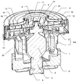
図1は、本発明の実施の形態1における電動送風機の断面斜視図、図2は、同電動送風機の一部拡大断面斜視図、図3は、同電動送風機のシール材支持体の半断面斜視図、図4は、同電動送風機のファンケースの斜視図である。
(Embodiment 1)
1 is a cross-sectional perspective view of an electric blower according to Embodiment 1 of the present invention, FIG. 2 is a partially enlarged cross-sectional perspective view of the electric blower, and FIG. 3 is a half-sectional perspective view of a sealing material support of the electric blower. 4 and 4 are perspective views of a fan case of the electric blower.
図1〜4において、本実施の形態における電動送風機は、図1〜4に示されるように電動機部40と送風機部41から構成されている。
1-4, the electric blower in this Embodiment is comprised from the
電動機部40は、一端側を開口した有底筒状のブラケット7と、ブラケット7の開口側を閉塞するフレーム8によりケーシング40aを構成している。ケーシング40aは固定子である界磁1を内蔵し、中央には回転子である電機子2を、軸受4により回転可能に収納している。電機子2は、電機子巻線(図示せず)に接続された整流子5を有し、ブラケット7に固定されたブラシユニット9を介して界磁巻線(図示せず)と電機子巻線を接続し通電することにより回転力を得ている。
The
送風機部41は、主にファン11、エアガイド10、ファンケース16から構成され、中央部に吸込口12を有する前面シュラウド13とそれに対抗する後面シュラウド14とそれらの間に固定される複数のブレード15とから構成されるファン11がフレーム8から突出した電機子回転軸3にナット6などで取り付けられている。フレーム8に取り付けられたエアガイド10は、ファン11から排出された気流を整流し電動機部40へ流しこむ役割を担っている。ファンケース16は、ファン11とエアガイド10を覆いフレーム8に圧入固定されている。ファンケース16の中央部には、吸気口17があり、ファン11の吸込口12へ気流を導く役目を担っている。
The
図2〜4に示されるように、本実施の形態における電動送風機のファンケース16は、吸気口17の端部が軸方向反ファン側に立ち上がる円筒部18を有している。この円筒部18は従来のファン側へ180度曲げられたベルマウス形状に比べ、加工が容易でプレス工程が削減できるだけでなく、割れや皹の発生も低減でき生産性を改善できる。また、別部材のシール材支持体26がファンケース16の外面側から取り付け構成されている。またシール材支持体26は、ベルマウス状垂下部27の内径面と反ファン側外周面とを大きなRで滑らかに形成したR部29を備えている。
As shown in FIGS. 2 to 4, the
シール材支持体26のファン側にはEVAなどの円盤環状のシール材25が取り付けられるリング状平面部28が存在し、リング状平面部28よりも反ファン側に底面部を有する溝部30が構成されている。この溝部30に円筒部18を挿入し、円筒部先端面19が溝底面31に当接することにより位置が確定し固定されている。
On the fan side of the
本構成により、溝底面31と円筒部先端面19が円周面で位置決めされるため、電機子
回転軸3に対し直角な平面を実現でき、シール材25と吸込口12との片接触を防止できる。
With this configuration, since the
また、溝部30の外周側内面33が円筒部18の外周面21と、溝部30の内周側外面32が円筒部18の内周面20と略接触することにより、溝底面31を含めて3面で接触することとなり、より確実な固定が実現でき、一部隙間が存在した場合でもラビリンス効果によりファンケース16内部と外部とのリーク風を防止できる。
Further, the outer peripheral side
また、シール材支持体26がファンケース16の外周側に位置することから、吸気圧などによりシール材支持体26がファン11側に荷重を受けてもファンケース16から外れることがなく、シール材支持体26の吸い込みによるファン破壊やモータロックなどの異常発生を確実に防止できる。
Further, since the sealing
以上のように構成された電動送風機によれば、溝部30の深さとファンケース16の円筒部18の長さとシール材25の厚みのいずれかを調整することにより、吸込口12の端部とシール材25が軽接触する最も効率が良い構成とすることが容易で、ファン11から排出された気流がファン11とファンケース16の間を通り、吸込口12へ循環するリ−ク風を制精度良く安全に防止でき、送風効率を改善することが出来る。
According to the electric blower configured as described above, by adjusting any of the depth of the
また、本実施の形態では、シール材25は、ベルマウス状垂下部27の外側面に当接し、且つ、円筒部18の内周面20にも当接するようにしている。この構成により、シール材25の内径とベルマウス状垂下部27の内径を近づけることになり、この寸法差での気流の乱れを小さくすることが可能である。
Further, in the present embodiment, the sealing
(実施の形態2)
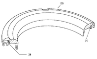
図5は、本発明の実施の形態2における電動送風機のシール材支持体の半断面斜視図、図6は、同電動送風機のファンケースの斜視図、図7は、同ファンケースにシール材支持体を装着した状態での斜視図、図8は、同シール材支持体の部分拡大図である。なお上記実施の形態1における電動送風機と同一部分については、同一符号を用いてその説明を省略する。
(Embodiment 2)
FIG. 5 is a half sectional perspective view of a sealing material support of an electric blower according to
本実施の形態における電動送風機は、図5、図6に示されるように、円筒部先端面19は、少なくとも1ケ以上の突出リブ22を有しており、シール材支持体26には、突出リブ22に対応する挿入孔34を設けたものである。
As shown in FIGS. 5 and 6, the electric blower in the present embodiment has at least one protruding
そして、図7、図8に示されるように突出リブ22を挿入孔34に挿入した後にその突出リブ22を外周側に折り曲げることにより、ファンケース16とシール材支持体26の固定をより確実に行うものである。
7 and FIG. 8, after inserting the protruding
本実施の形態における電動送風機によれば、熱膨張や振動などによりファンケース16とシール材支持体26の嵌合が緩くなっても、ファンケース16とシール材支持体26が外れることがなくより安全に固定が実現できる。また、ファンケース16とシール材支持体26の嵌合代を緩く設定しても外れることがないため、嵌合を緩めて作業性を向上させることができる。
According to the electric blower in the present embodiment, even if the
尚、円筒部18と溝部30は、内外周面で接触した底面部での孔であり、突出リブ22の先端部を外周側へ折り曲げることにより、微小な隙間はラビリンス効果により流出する気流は微量であり問題となる程の漏れ気流は発生しない。
The
(実施の形態3)
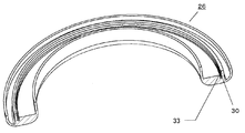
図9は、本発明の実施の形態3における電動送風機のシール材支持体の半断面斜視図、図10は、同電動送風機のファンケースの要部拡大斜視図、図11は、同シール材支持体をファンケースに取り付け前の状態を示す斜視図、図12は、同シール材支持体をファンケースに取り付けた状態を示す斜視図である。なお上記実施の形態における電動送風機と同一部分については、同一符号を用いてその説明を省略する。
(Embodiment 3)
FIG. 9 is a half sectional perspective view of a sealing material support of an electric blower according to
本実施の形態における電動送風機は、図9、図10に示されるように、上記実施の形態2で述べた突出リブ22の中央にスリット23を、両端部に突起部24をそれぞれ設け、挿入孔34には、突起部24の幅と同等幅のスリット36を設けたものである。尚、スリット36は窪み35と一体に形成されても構わない。
As shown in FIGS. 9 and 10, the electric blower in the present embodiment is provided with a
挿入孔34の幅は突出リブ22の幅と略同一で、突起部24の先端の突部間の幅を、挿入孔34の幅よりも大きく、スリット36の幅は、突起部24間の幅と略同等に設定されている。
The width of the
本実施の形態における電動送風機は以上のように構成されているので、図11、図12に示されるように、シール材支持体26をファンケース16に挿入すると、突起部24間が弾性により挿入孔34の幅分だけ狭くなり、挿入孔34を通過しスリット36部に達したところで、弾性により元の寸法に戻り、突起部24が掛かり止めとなり、ファンケース16とシール材支持体26を固定するものである。
Since the electric blower according to the present embodiment is configured as described above, when the sealing
本実施の形態では、突出リブ22を挿入孔34に挿入したあと曲げを行う必要がないので、挿入という1工程だけで安価にファンケース16とシール材支持体26を固定できる。
In this embodiment, since it is not necessary to bend after inserting the protruding
また、ベルマウス状垂下部27の内径面と反ファン側外周面とをR1以上の大きなRで滑らかにR部29を形成すると共に、挿入孔34に挿入された突起部24がR部29よりも外周側に位置させることにより、最も流速が早く吸気性能に影響を与えるR部29に窪みや突起が存在せず気流を乱すことがないため、性能低下や騒音増加を防止することができる。
In addition, the inner diameter surface of the bell mouth-shaped hanging
また、挿入孔34を他部よりもファン11側へ凹んだ窪み35に設けるなどして、シール材支持体26の外面よりも突起部24が突出しないように寸法設定すれば、突起部24による気流の乱れを防止して、性能低下や騒音増加を防止できる。この時、突出リブ22の先端部がシール材支持体26の表面と略同一面を形成することが望ましい。
Further, if the
なお、シール材25の外径と円筒部18の内周面20を接触させることにより、ファンケース16とシール材支持体26をシールすることが可能となり、シール材支持体26に設けた挿入孔34と突起部24との隙間が大きくてもシール性を維持できるため、それぞれの寸法公差を広げることが可能となり製造コスト低減を実現できる。また、シール材25の内外径部を同時に規制することにより前記シール性が高まるだけでなく、シール材25の軸ずれも防止できよりシール性を高めることができる。
The
また、上記実施の形態における電動送風機において、シール材25とベルマウス状垂下部27の外周面、シール材25と円筒部18の内周面20、円筒部18と溝部30の内周側外面32の接着を同一の接着剤(図示せず)にて同時に行うようにすれば、リング状平面部28(図3参照)に多目の接着剤を塗布するだけで、シール材25を押し付けた場合に接触面からはみ出る接着剤がそれぞれに流れ込むことになり、全ての接着固定が実現でき、安価で確実な固定が実現できる。
In the electric blower according to the above-described embodiment, the outer peripheral surface of the sealing
(実施の形態4)
図13は、本発明の実施の形態4における電動送風機のシール材支持体の半断面斜視図、図14は同電動送風機のファンケースの斜視図、図15は、同シール材支持体とファンケースの組み立て状態を示す断面斜視図である。なお上記実施の形態における電動送風機と同一部分については、同一符号を用いてその説明を省略する。
(Embodiment 4)
FIG. 13 is a half sectional perspective view of a sealing material support body of an electric blower according to Embodiment 4 of the present invention, FIG. 14 is a perspective view of a fan case of the electric blower, and FIG. 15 is the sealing material support body and the fan case. It is a cross-sectional perspective view which shows the assembly state of. In addition, about the same part as the electric blower in the said embodiment, the description is abbreviate | omitted using the same code | symbol.
本実施の形態における電動送風機は、図13〜15に示すように、ファンケース16の円筒部18にねじ切りを付加し、シール材支持体26の溝部30の外周側内面33にはそれに対応するねじ切りを付加し、シール材支持体26を円筒部18にねじ込むことによりファンケース16とシール材支持体26の固定を行うようにしたものである。本実施の形態によれば、シール材支持体26の取り外しが容易であり、シール状態の確認や交換が最も容易であり、より安定したシール状態を実現できる。
As shown in FIGS. 13 to 15, the electric blower in the present embodiment adds threading to the
また、図16〜17に示されるように、シール材支持体26の外周側をファン11の外径近傍まで延長し整流板を兼ねる形状とすることで、吸気口17へ流入する気流をより滑らかに誘導することが可能でより送風効率の向上が実現できる。
Also, as shown in FIGS. 16 to 17, by extending the outer peripheral side of the
また、ファンケース16を覆うように樹脂板が存在するため、防音対策も実現できる。この場合、シール材支持体26とファンケース16の間に防音材(図示せず)を配置したり、シール材支持体26の整流板部37に誘導フィン(図示せず)を付加するなどを行うとより効果を高めることが可能である。
Further, since a resin plate is present so as to cover the
また、特に図示しないが、上記実施の形態における電動送風機を電気掃除機に搭載すれば、安価で安全で高性能な電気掃除機を実現できる。 Although not particularly illustrated, if the electric blower in the above embodiment is mounted on a vacuum cleaner, an inexpensive, safe and high-performance vacuum cleaner can be realized.
以上のように、本発明にかかる電動送風機は、ファンケースの吸気口に外側からシール材支持体を取り付けると言う簡単な方法で、精度良くファンケースとファンとのリーク風を防止でき、且つ、シール材支持体が吸い込まれると言う危険性がなく安全に高性能な電動送風機を提供することができ、その電動送風機を搭載することで高性能な電気掃除機が実現できるもので、家庭用、業務用に限らず各種電気掃除機に適用できる。 As described above, the electric blower according to the present invention can prevent leakage air between the fan case and the fan with high accuracy by a simple method of attaching the sealing material support to the air inlet of the fan case from the outside, and There is no danger that the sealing material support is sucked in, and it is possible to provide a high-performance electric blower safely, and a high-performance vacuum cleaner can be realized by installing the electric blower. It can be applied to various vacuum cleaners, not just for business use.
1 界磁
2 電機子
3 電機子回転軸
4 軸受
5 整流子
6 ナット
7 ブラケット
8 フレーム
9 ブラシユニット
10 エアガイド
11 ファン
12 吸込口
13 前面シュラウド
14 後面シュラウド
15 ブレード
16 ファンケース
17 吸気口
18 円筒部
19 円筒部先端面
20 内周面
21 外周面
22 突出リブ
23,36 スリット
24 突起部
25 シール材
26 シール材支持体
27 ベルマウス状垂下部
28 リング状平面部
29 R部
30 溝部
31 溝底面
32 内周側外面
33 外周側内面
34 挿入孔
35 窪み
37 整流板部
DESCRIPTION OF SYMBOLS 1
Claims (9)
Priority Applications (1)
| Application Number | Priority Date | Filing Date | Title |
|---|---|---|---|
| JP2014212467A JP6450928B2 (en) | 2014-10-17 | 2014-10-17 | Electric blower and electric vacuum cleaner using the same |
Applications Claiming Priority (1)
| Application Number | Priority Date | Filing Date | Title |
|---|---|---|---|
| JP2014212467A JP6450928B2 (en) | 2014-10-17 | 2014-10-17 | Electric blower and electric vacuum cleaner using the same |
Publications (2)
| Publication Number | Publication Date |
|---|---|
| JP2016079901A JP2016079901A (en) | 2016-05-16 |
| JP6450928B2 true JP6450928B2 (en) | 2019-01-16 |
Family
ID=55958059
Family Applications (1)
| Application Number | Title | Priority Date | Filing Date |
|---|---|---|---|
| JP2014212467A Active JP6450928B2 (en) | 2014-10-17 | 2014-10-17 | Electric blower and electric vacuum cleaner using the same |
Country Status (1)
| Country | Link |
|---|---|
| JP (1) | JP6450928B2 (en) |
Families Citing this family (3)
| Publication number | Priority date | Publication date | Assignee | Title |
|---|---|---|---|---|
| CN106949078A (en) * | 2017-04-28 | 2017-07-14 | 广东美的环境电器制造有限公司 | Pedestal and bladeless fan for bladeless fan |
| CN106870421B (en) * | 2017-04-28 | 2023-11-24 | 广东美的环境电器制造有限公司 | Base for bladeless fan and bladeless fan |
| CN108272394A (en) * | 2018-02-06 | 2018-07-13 | 马根昌 | Sweeping robot |
Family Cites Families (4)
| Publication number | Priority date | Publication date | Assignee | Title |
|---|---|---|---|---|
| JP3424955B2 (en) * | 1993-05-13 | 2003-07-07 | 松下電器産業株式会社 | How to assemble an electric blower |
| JP2003083294A (en) * | 2001-09-05 | 2003-03-19 | Toshiba Tec Corp | Motor fan and electric cleaner |
| DE10148510C1 (en) * | 2001-10-01 | 2003-06-18 | Bsh Bosch Siemens Hausgeraete | Seal for use in a blower arrangement |
| EP2829736B1 (en) * | 2012-03-21 | 2016-02-24 | Panasonic Corporation | Electric air blower |
-
2014
- 2014-10-17 JP JP2014212467A patent/JP6450928B2/en active Active
Also Published As
| Publication number | Publication date |
|---|---|
| JP2016079901A (en) | 2016-05-16 |
Similar Documents
| Publication | Publication Date | Title |
|---|---|---|
| TW201014124A (en) | Inner-rotor type fan | |
| JP6504754B6 (en) | Electric blower and vacuum cleaner using the same | |
| JP6450928B2 (en) | Electric blower and electric vacuum cleaner using the same | |
| US10113551B2 (en) | Axial flow fan | |
| WO2016121447A1 (en) | Electric air blower and electric vacuum cleaner using same | |
| JP5316192B2 (en) | Electric blower and electric vacuum cleaner using the same. | |
| JP2016053315A (en) | Centrifugal fan, electric blower and vacuum cleaner using the same | |
| JP2011001939A (en) | Electric blower | |
| JP4867677B2 (en) | Electric blower and electric vacuum cleaner using it | |
| JP2009041391A (en) | Electric blower and vacuum cleaner using the same | |
| JP2987286B2 (en) | Electric blower | |
| JP2017216794A (en) | motor | |
| JP6142288B2 (en) | Electric blower and electric vacuum cleaner using the same | |
| JP5369557B2 (en) | Electric blower | |
| JP2009095534A (en) | Electric blower | |
| JPWO2006025105A1 (en) | Electric motor and electric blower provided with the same | |
| JPH11201093A (en) | Electrically driven air blower | |
| JP4978211B2 (en) | Electric blower and electric vacuum cleaner using it | |
| JP2013199871A (en) | Electric blower | |
| JP2007321670A (en) | Electric blower and vacuum cleaner using same | |
| CN217898266U (en) | Air compressor | |
| CN211557076U (en) | Motor assembly | |
| JP2007270637A (en) | Motor-driven blower | |
| JP4851791B2 (en) | Electric blower | |
| JP2008038860A (en) | Electric blower |
Legal Events
| Date | Code | Title | Description |
|---|---|---|---|
| RD01 | Notification of change of attorney |
Free format text: JAPANESE INTERMEDIATE CODE: A7421 Effective date: 20160520 |
|
| A621 | Written request for application examination |
Free format text: JAPANESE INTERMEDIATE CODE: A621 Effective date: 20170718 |
|
| A977 | Report on retrieval |
Free format text: JAPANESE INTERMEDIATE CODE: A971007 Effective date: 20180510 |
|
| A131 | Notification of reasons for refusal |
Free format text: JAPANESE INTERMEDIATE CODE: A131 Effective date: 20180515 |
|
| A521 | Written amendment |
Free format text: JAPANESE INTERMEDIATE CODE: A523 Effective date: 20180612 |
|
| TRDD | Decision of grant or rejection written | ||
| A01 | Written decision to grant a patent or to grant a registration (utility model) |
Free format text: JAPANESE INTERMEDIATE CODE: A01 Effective date: 20181030 |
|
| A61 | First payment of annual fees (during grant procedure) |
Free format text: JAPANESE INTERMEDIATE CODE: A61 Effective date: 20181112 |
|
| R151 | Written notification of patent or utility model registration |
Ref document number: 6450928 Country of ref document: JP Free format text: JAPANESE INTERMEDIATE CODE: R151 |