US9639120B2 - Heat dissipation structure of wearable electronic device - Google Patents
Heat dissipation structure of wearable electronic device Download PDFInfo
- Publication number
- US9639120B2 US9639120B2 US14/571,299 US201414571299A US9639120B2 US 9639120 B2 US9639120 B2 US 9639120B2 US 201414571299 A US201414571299 A US 201414571299A US 9639120 B2 US9639120 B2 US 9639120B2
- Authority
- US
- United States
- Prior art keywords
- heat conduction
- section
- heat
- receiving space
- wearable
- Prior art date
- Legal status (The legal status is an assumption and is not a legal conclusion. Google has not performed a legal analysis and makes no representation as to the accuracy of the status listed.)
- Active, expires
Links
Images


Classifications
-
- G—PHYSICS
- G06—COMPUTING; CALCULATING OR COUNTING
- G06F—ELECTRIC DIGITAL DATA PROCESSING
- G06F1/00—Details not covered by groups G06F3/00 - G06F13/00 and G06F21/00
- G06F1/16—Constructional details or arrangements
- G06F1/1613—Constructional details or arrangements for portable computers
- G06F1/1633—Constructional details or arrangements of portable computers not specific to the type of enclosures covered by groups G06F1/1615 - G06F1/1626
- G06F1/1637—Details related to the display arrangement, including those related to the mounting of the display in the housing
- G06F1/1643—Details related to the display arrangement, including those related to the mounting of the display in the housing the display being associated to a digitizer, e.g. laptops that can be used as penpads
-
- G—PHYSICS
- G06—COMPUTING; CALCULATING OR COUNTING
- G06F—ELECTRIC DIGITAL DATA PROCESSING
- G06F1/00—Details not covered by groups G06F3/00 - G06F13/00 and G06F21/00
- G06F1/16—Constructional details or arrangements
- G06F1/1613—Constructional details or arrangements for portable computers
- G06F1/163—Wearable computers, e.g. on a belt
-
- G—PHYSICS
- G06—COMPUTING; CALCULATING OR COUNTING
- G06F—ELECTRIC DIGITAL DATA PROCESSING
- G06F1/00—Details not covered by groups G06F3/00 - G06F13/00 and G06F21/00
- G06F1/16—Constructional details or arrangements
- G06F1/20—Cooling means
- G06F1/203—Cooling means for portable computers, e.g. for laptops
Definitions
- the present invention relates generally to a wearable electronic device, and more particularly to a heat dissipation structure of wearable electronic device for dissipating the heat generated by the wearable electronic device.
- the intelligent wearable electronic device is equipped with more and more components such as touch screen, central processor unit (CPU), graphic processing unit (GPU) and satellite positioning chip.
- the intelligent watch is connectable to other mobile devices via Bluetooth or network.
- a SIN card can be inserted into the intelligent watch to access to 3G or 4G network and make phone calls.
- the conventional intelligent watch (or so-called wearable watch) operates or executes a function
- the main operation/processing chips such as the CPU and the GPU inside the intelligent watch will generate heat.
- the heat can be hardly quickly dissipated outward.
- the heat will continuously accumulate on and around the CPU and GPU in the intelligent watch. This will lead to deterioration of execution efficiency of the intelligent watch or even shutdown of the intelligent watch.
- the heat will locally accumulate in the intelligent watch so that when a user wears the intelligent watch, the wrist section of the user will feel uncomfortable. Accordingly, it has become a critical issue how to solve the heat dissipation problem of the intelligent watch and various wearable mobile devices.
- the heat dissipation structure of wearable electronic device of the present invention includes a wearable main body and a wearable strap body.
- the wearable main body includes a receiving space, a circuit board and multiple electronic components.
- the electronic components are arranged on the circuit board.
- the circuit board with the electronic components is received in the receiving space.
- At least one of the electronic components is a heat source.
- the wearable strap body is connected with the wearable main body.
- the wearable strap body has a heat conduction section and a protection section.
- the protection section encloses the heat conduction section. A section of the heat conduction section is exposed to an interior of the receiving space without being enclosed by the protection section.
- the exposed section of the heat conduction section is in contact with the corresponding heat source.
- the heat dissipation performance of the wearable electronic device is greatly enhanced. Accordingly, the heat will not accumulate in the wearable electronic device and a user can wear the wearable electronic device more comfortably.
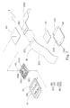
- FIG. 1 is a perspective exploded view of a first embodiment of the present invention
- FIG. 2 is a perspective assembled view of the first embodiment of the present invention
- FIG. 3 is a sectional assembled view of the first embodiment of the present invention.
- FIG. 4 is a sectional assembled view of a second embodiment of the present invention.
- FIG. 5 is a perspective exploded view of a third embodiment of the present invention.
- FIG. 6 is a perspective assembled view of the third embodiment of the present invention.
- FIG. 7 is a perspective exploded view of a fourth embodiment of the present invention.
- FIG. 8 is a perspective assembled view of the fourth embodiment of the present invention.
- FIG. 9 is a sectional assembled view of the fourth embodiment of the present invention.
- FIG. 10 is a sectional assembled view of a fifth embodiment of the present invention.
- FIG. 11 is a perspective exploded view of a sixth embodiment of the present invention.
- FIG. 12 is a perspective assembled view of the sixth embodiment of the present invention.
- FIG. 13 is a perspective exploded view of a seventh embodiment of the present invention.
- FIG. 14 is a sectional assembled view of the seventh embodiment of the present invention.
- FIG. 15 is another perspective exploded view of the seventh embodiment of the present invention.
- FIG. 16 is another sectional assembled view of the seventh embodiment of the present invention.
- FIG. 17 is a sectional assembled view of an eighth embodiment of the present invention.
- FIG. 18 is another sectional assembled view of the eighth embodiment of the present invention.
- FIG. 19 is a perspective exploded view of a ninth embodiment of the present invention.
- FIG. 20 is another perspective exploded view of the ninth embodiment of the present invention.
- FIG. 1 is a perspective exploded view of a first embodiment of the present invention.
- FIG. 2 is a perspective assembled view of the first embodiment of the present invention.
- FIG. 3 is a sectional assembled view of the first embodiment of the present invention.
- the heat dissipation structure 1 of wearable electronic device of the present invention is, but not limited to, a wearable watch (intelligent watch) for illustration purposes only.
- the wearable electronic device includes a wearable main body 10 and a wearable strap body 20 .
- the wearable main body 10 includes a receiving space 1042 , a circuit board 105 , multiple electronic components 1051 , a touch display module 101 , a battery 102 , an upper frame body 103 and a lower frame body 104 .
- the upper frame body 103 receives the touch display module 101 therein.
- the touch display module 101 has a touch display face 1011 and a bottom face 1012 .
- the touch display face 1011 is for a user to touch, operate and watch the displayed information.
- the bottom face 1012 faces the circuit board 105 . In practice, the circuit board 105 is locked on the bottom face 1012 by means of multiple screws (not shown).
- the upper frame body 103 is mated with the lower frame body 104 to cover the same.
- the lower frame body 104 is formed with the receiving space 1042 and multiple recesses 1041 .
- a central section of one face of the lower frame body 104 is recessed to form the receiving space 1042 for receiving the circuit board 105 , the electronic components 1051 and the battery 102 (such as lithium battery).
- the recesses 1041 are formed on two opposite sides of one face of the lower frame body 104 in adjacency to and in communication with the receiving space 1042 .
- the battery 102 is positioned on the bottom of the receiving space 1042 .
- the circuit board 105 preferably is, but not limited to, a printed circuit board (PCB) for illustration purposes only.
- the electronic components 1051 are arranged on the circuit board 105 .
- At least one of the electronic components 1051 is a heat source 10511 .
- One of the heat sources is a central processor unit (CPU), while the other of the heat sources is a graphic processing unit (GPU).
- the rest electronic components 1051 are memory (such as flash memory) and other components (such as capacitors, resistors, transistors and IC chips).
- the heat sources 10511 are not limited to the above two heat sources 10511 .
- the other electronic components 1051 can be also heat sources 10511 the heat of which needs to be dissipated.
- the IC chips or battery can be also the heat sources 10511 .
- the wearable strap body 20 is a flexible wearable strap body (soft watchstrap) for illustration.
- the wearable strap body 20 is connected with the wearable main body 10 .
- the wearable strap body 20 has a heat conduction section 201 and a protection section 205 .
- the protection section 205 is made of flexible plastic material.
- the protection section 205 encloses the heat conduction section 201 .
- a section of the heat conduction section 201 is exposed to the interior of the receiving space 1042 without being enclosed by the protection section 205 . That is, the other section of the heat conduction section 201 is enclosed in the protection section 205 .
- This section is positioned on two lateral sides of the wearable main body 10 for a user to wear.
- the exposed section of the heat conduction section 201 in the receiving space 1042 is bridged over the receiving space 1042 to extend from one recess 1041 of the lower frame body 104 into the other opposite recess 1041 of the lower frame body 104 .
- One face of the exposed section of the heat conduction section 201 is in contact with (or in attachment to) the corresponding heat source 10511 (the CPU and the GPU).
- the exposed section of the heat conduction section 201 absorbs the heat generated by the heat source 10511 and quickly conducts the heat to the other part of the heat conduction section 201 to dissipate the heat outside.
- the circuit board 105 is positioned on upper side of the exposed section of the heat conduction section 201 , while the battery 102 is positioned under the exposed section of the heat conduction section 201 for illustration.
- the arrangement positions of the circuit board 105 and the battery 102 can be changed.
- the circuit board can be positioned under the heat conduction section 201 in adjacency to the battery 102 .
- the heat source 10511 is still in attachment to the exposed section of the heat conduction section 201 .
- the wearable strap body 20 is an integrated elongated watchstrap for illustration.
- a middle section of the wearable strap body 20 (that is, the exposed section of the heat conduction section 201 ) is received in the receiving space 1042 to absorb the heat of the heat source and quickly conduct the heat to the front section and/or rear section of the wearable strap body 20 on at least one side of the wearable main body 10 .
- the heat conduction section 201 enclosed in the front and rear sections will absorb the heat to dissipate the heat outside. Accordingly, the heat generated by the CPU and GPU of the wearable main body 10 will not accumulate in the wearable main body 10 . In this case, the CPU and GPU can stably and quickly operate. In addition, a user can wear the wearable main body more comfortably.
- the heat conduction section 201 is made of graphite, metal foil or a combination thereof.
- the heat conduction section 201 has, but not limited to, three heat conduction layers for illustration purposes only.
- the heat conduction section 201 can be alternatively designed with one heat conduction layer (graphite or metal foil), two heat conduction layers, four heat conduction layers or more heat conduction layers.
- the heat conduction section 201 has a first heat conduction layer 2011 , a second heat conduction layer 2012 and a third heat conduction layer 2013 .
- the first and third heat conduction layers 2011 , 2013 are made of metal foils, and preferably copper foils.
- the second heat conduction layer 2012 is made of graphite material.
- the material of the heat conduction layers is not limited to the above material.
- the first, second and third heat conduction layers 2011 , 2012 , 2013 can be made of graphite, metal foils (gold foils, silver foils, copper foils or aluminum foils) or the combination of graphite and metal foils.
- the first and second heat conduction layers 2011 , 2012 are made of graphite
- the third heat conduction layer 2013 is made of copper foil
- the first heat conduction layer 2011 is made of copper foil
- the second and third heat conduction layers 2012 , 2013 are made of graphite, and so on.
- the second heat conduction layer 2012 is sandwiched between the first heat conduction layer 2011 and the third heat conduction layer 2013 .
- the other face of the exposed section of the heat conduction section 201 (that is, the outer face of the third heat conduction layer 2013 ) is attached to the battery 102 .
- the protection section 205 encloses the outer faces of the first and third heat conduction layers 2011 , 2013 of the other section of the heat conduction section 201 , (that is, the other section of the heat conduction section 201 , which is enclosed in the front and rear sections of the wearable strap body 20 ).
- the outer face of the first heat conduction layer 2011 of the exposed section of the heat conduction section 201 in the receiving space 1042 (that is, the exposed section of the heat conduction section 201 at the middle of the wearable strap body 20 ) is attached to the heat sources 10511 (the CPU and the GPU). Accordingly, the first heat conduction layer 2011 will absorb the heat generated by the CPU and the GPU and quickly conduct the heat to the second and third heat conduction layers 2012 , 2013 . At the same time, the third heat conduction layer 2013 will absorb the heat of the battery 102 .
- the heat is then transferred to the other section of the heat conduction section 201 , (that is, the front and rear sections of the wearable strap body 20 on two sides of the wearable main body 10 ) and dissipated outward. Accordingly, the heat of the wearable main body 10 is quickly dissipated.
- the heat conduction section 201 is enclosed in the wearable strap body 20 .
- a part of the heat conduction section 201 is exposed to attach to the heat source 10511 of the wearable main body 10 , whereby the heat dissipation performance of the wearable electronic device is greatly enhanced. Accordingly, the heat will not accumulate in the wearable main body 10 and a user can wear the wearable main body 10 more comfortably.
- FIG. 4 is a sectional assembled view of a second embodiment of the present invention.
- the second embodiment is substantially identical to the first embodiment in structure, connection relationship and effect and thus will not be repeatedly described.
- the second embodiment is mainly different from the first embodiment in that the heat conduction section 201 is a flexible heat pipe. That is, the heat conduction section 201 is a flexible heat pipe made of flexible metal material (such as copper material), flexible thin heat pipe made of flexible metal material (such as copper material or aluminum material) or flexible thin heat pipe made of flexible nonmetal material (such as plastic, rubber or polyethylene terephthalate, PET).
- the protection section 205 is made of flexible plastic material or hard plastic material. In this embodiment, the protection section 205 is made of flexible plastic material for illustration.
- the heat conduction section 201 is a flexible heat pipe for illustration.
- the heat conduction section 201 has a chamber 2014 and a capillary structure 2015 .
- a working fluid 2016 is filled in the chamber 2014 .
- the working fluid 2016 is selected from a group consisting of pure water, inorganic compound, alcohol group, ketone group, liquid metal, coolant and organic compound.
- the capillary structure 2015 is formed on inner wall face of the chamber 2014 .
- the other face of the exposed section of the heat conduction section 201 in the receiving space 1042 is attached to the battery 102 .
- One face of the exposed section of the heat conduction section 201 (that is, one face of the flexible heat pipe) is attached to the heat sources 10511 (the CPU and the GPU).
- the exposed section of the heat conduction section 201 absorbs the heat generated by the heat sources 10511 and the battery 102 and conducts the heat into the chamber 2014 for heat exchange.
- the vapor working fluid spreads within the chamber 2014 to the chamber 2014 of the other section of the heat conduction section 201 , (that is, the chamber of the front and rear sections of the wearable strap body 20 on two sides of the wearable main body 10 ).
- the vapor working fluid is cooled and condensed in the chamber 2014 of the other section of the heat conduction section 201 .
- the liquid working fluid flows back to the exposed section of the heat conduction section 201 (at the middle of the wearable strap body 20 ) for next vapor-liquid circulation. Accordingly, the heat generated by the heat sources 10511 of the wearable main body 10 can be quickly dissipated.
- the heat conduction section 201 enclosed in the wearable strap body 20 is a flexible heat pipe. A part of the heat conduction section 201 is exposed to attach to the heat sources 10511 of the wearable main body 10 , whereby the heat dissipation performance of the wearable electronic device is greatly enhanced. Accordingly, the heat will not accumulate in the wearable main body 10 and a user can wear the wearable main body 10 more comfortably.
- FIG. 5 is a perspective exploded view of a third embodiment of the present invention.
- FIG. 6 is a perspective assembled view of the third embodiment of the present invention.
- the third embodiment is substantially identical to the second embodiment in structure, connection relationship and effect and thus will not be repeatedly described.
- the third embodiment is different from the second embodiment in that the heat conduction section 201 is a heat pipe made of hard metal material and the protection section 205 is made of hard plastic material. Therefore, the front and rear sections of the wearable strap body 20 , (that is, the other section of the heat conduction section 201 enclosed in the protection section 205 ) are inward bent toward the center of the lower frame body 104 and secured to form a fitting opening 208 . A user can directly wear the wearable main body through the fitting opening 208 .
- the heat conduction section 201 enclosed in the wearable strap body 20 is a heat pipe. A part of the heat conduction section 201 is exposed to attach to the heat sources 10511 of the wearable main body 10 , whereby the heat dissipation performance of the wearable electronic device is greatly enhanced. Accordingly, the heat will not accumulate in the wearable main body 10 and a user can wear the wearable main body 10 more comfortably.
- FIG. 7 is a perspective exploded view of a fourth embodiment of the present invention.
- FIG. 8 is a perspective assembled view of the fourth embodiment of the present invention.
- FIG. 9 is a sectional assembled view of the fourth embodiment of the present invention.
- the fourth embodiment is substantially identical to the first embodiment in structure, connection relationship and effect and thus will not be repeatedly described.
- the fourth embodiment is different from the first embodiment in that the wearable strap body 20 is changed from the above integrated elongated watchstrap into a two-piece elongated watchstrap. Also, the exposed section of the heat conduction section 201 of the wearable strap body 20 is not attached to the heat sources 10511 .
- the exposed section of the heat conduction section 201 is attached to a conduction section 207 attached to the heat sources 10511 .
- the exposed section of the heat conduction section 201 can be not only attached to the conduction section 207 attached to the heat sources 10511 , but also attached to the corresponding heat sources 10511 .
- the heat conduction section 201 has a first heat conduction body 202 and a second heat conduction body 203 .
- the protection section 205 has a first protection body 2051 and a second protection body 2052 .
- the first and second protection bodies 2051 , 2052 respectively enclose the first and second heat conduction bodies 202 , 203 .
- a section of the first and second heat conduction bodies 202 , 203 is exposed to the interior of the receiving space 1042 and is not enclosed by the first and second protection bodies 2051 , 2052 . That is, the other section of the first and second heat conduction bodies 202 , 203 is enclosed in the first and second protection bodies 2051 , 2052 .
- This section is positioned on two sides of the wearable main body 10 for a user to wear.
- the wearable strap body 20 is a two-piece elongated watchstrap for illustration.
- the rear sections of the wearable strap body 20 (that is, the exposed sections of the first and second heat conduction bodies 202 , 203 ) are received in the receiving space 1042 for indirectly absorbing the heat (via the conduction section 207 ) and quickly conducting the heat to the front and middle sections of the wearable strap body 20 on two sides of the wearable main body 10 .
- the first and second heat conduction bodies 202 , 203 enclosed in the front and middle sections of the wearable strap body 20 will absorb the heat to dissipate the heat outward. Therefore, the heat generated by the CPU and the GPU of the wearable main body 10 will not accumulate in the wearable main body 10 . Accordingly, the CPU and the GPU can stably and quickly operate and the user can wear the wearable main body more comfortably.
- the exposed sections of the first and second heat conduction bodies 202 , 203 are respectively received in the recesses 1041 and protrude to the center of the receiving space 1042 .
- the exposed sections of the first and second heat conduction bodies 202 , 203 are opposite to each other.
- the battery 102 is positioned under the exposed sections of the first and second heat conduction bodies 202 , 203 .
- Each of the first and second heat conduction bodies 202 , 203 has a first heat conduction layer 2021 , 2031 , a second heat conduction layer 2022 , 2032 and a third heat conduction layer 2023 , 2033 .
- the first and third heat conduction layers 2021 , 2031 , 2023 , 2033 of the first and second heat conduction bodies 202 , 203 are made of metal foils (such as gold foils, silver foils, copper foils or aluminum foils).
- the first and third heat conduction layers 2021 , 2031 , 2023 , 2033 of the first and second heat conduction bodies 202 , 203 are made of copper foils for illustration.
- the second heat conduction layers 2022 , 2032 of the first and second heat conduction bodies 202 , 203 are made of graphite material.
- the first and second protection bodies 2051 , 2052 are made of flexible plastic material.
- the second heat conduction layer 2022 of the first heat conduction body 202 is sandwiched between the first and third heat conduction layers 2021 , 2023 of the first heat conduction body 202 .
- the second heat conduction layer 2032 of the second heat conduction body 203 is sandwiched between the first and third heat conduction layers 2031 , 2033 of the second heat conduction body 203 .
- the first and second protection bodies 2051 , 2052 respectively encloses the outer faces of the first and third heat conduction layers 2021 , 2031 , 2023 , 2033 of the other sections of the first and second heat conduction bodies 202 , 203 , (that is, the heat conduction section 201 enclosed in the front and middle sections of the wearable strap body 20 ).
- the wearable main body 10 further includes a conduction section 207 received in the receiving space 1042 and positioned right under the circuit board 105 .
- the first and second heat conduction bodies 202 , 203 are positioned under the conduction section 207 , that is, the conduction section 207 is positioned on upper sides of the first and second heat conduction bodies 202 , 203 .
- the conduction section 207 is, but not limited to, a vapor chamber for illustration purposes only. In practice, the conduction section 207 can be alternatively a heat pipe or other heat conduction component.
- the vapor chamber (the conduction section 207 ) has a chamber 2071 , a capillary structure 2072 and multiple support columns 2073 .
- a working fluid 2074 is filled in the chamber 2071 .
- the working fluid 2074 is selected from a group consisting of pure water, inorganic compound, alcohol group, ketone group, liquid metal, coolant and organic compound.
- the capillary structure 2072 is formed on inner wall face of the chamber 2071 .
- the support columns 2073 are received in the chamber 2071 . Top ends and bottom ends of the support columns 2073 respectively abut against upper and lower walls of the chamber 2071 .
- Two opposite sides of one face of the conduction section 207 respectively contact one face of the corresponding exposed sections of the first and second heat conduction bodies 202 , 203 .
- the rest part of the face of the conduction section 207 is attached to the battery 102 .
- the other face of the conduction section 207 is attached to the heat sources 10511 , (that is, the CPU and the GPU) on the circuit board 105 .
- the other face of the conduction section 207 corresponds to the bottom face 1012 of the touch display module 101 .
- the conduction section 207 absorbs the heat generated by the heat sources 10511 and the battery 102 and conducts the heat to the outer faces of the first heat conduction layers 2021 , 2031 of the exposed sections of the first and second heat conduction bodies 202 , 203 . Then the first heat conduction layers 2021 , 2031 of the exposed sections of the first and second heat conduction bodies 202 , 203 will quickly conduct the heat to the second and third heat conduction layers 2022 , 2023 , 2032 , 2033 .
- the heat is transferred to the other sections of the first and second heat conduction bodies 202 , 203 , (that is, the front and middle sections of the wearable strap body 20 on two sides of the wearable main body 10 ) and dissipated outward. Accordingly, the heat of the wearable main body 10 can be quickly dissipated.
- the first and second heat conduction bodies 202 , 203 are enclosed in the wearable strap body 20 .
- a part of the first and second heat conduction bodies 202 , 203 is exposed to attach to the conduction section 207 .
- the conduction section 207 is attached to the heat sources 10511 of the wearable main body 10 , whereby the heat dissipation performance of the wearable electronic device is greatly enhanced. Accordingly, the heat will not accumulate in the wearable main body 10 and a user can wear the wearable main body 10 more comfortably.
- FIG. 10 is a sectional assembled view of a fifth embodiment of the present invention.
- the fifth embodiment is substantially identical to the fourth embodiment in structure, connection relationship and effect and thus will not be repeatedly described.
- the fifth embodiment is mainly different from the fourth embodiment in that the heat conduction section 201 is a flexible heat pipe. That is, the first and second heat conduction bodies 202 , 203 are flexible heat pipes made of flexible metal material (such as copper material).
- Each of the first and second heat conduction bodies 202 , 203 has a chamber 2024 , 2034 and a capillary structure 2025 , 2035 .
- a working fluid 2026 , 2036 is filled in the chamber 2024 , 2034 of each of the first and second heat conduction bodies 202 , 203 .
- the working fluid 2026 , 2036 is selected from a group consisting of pure water, inorganic compound, alcohol group, ketone group, liquid metal, coolant and organic compound.
- the capillary structure 2025 , 2035 of each of the first and second heat conduction bodies 202 , 203 is formed on inner wall face of the chamber 2024 , 2034 .
- the first and second protection bodies 2051 , 2052 are made of flexible plastic material or hard plastic material. In this embodiment, the first and second protection bodies 2051 , 2052 are made of flexible plastic material for illustration.
- the first and second heat conduction bodies 202 , 203 enclosed in the wearable strap body 20 are flexible heat pipes.
- a part of the first and second heat conduction bodies 202 , 203 is attached to the conduction section 207 .
- the conduction section 207 is attached to the heat sources 10511 of the wearable main body 10 , whereby the heat dissipation performance of the wearable electronic device is greatly enhanced. Accordingly, the heat will not accumulate in the wearable main body 10 and a user can wear the wearable main body 10 more comfortably.
- FIG. 11 is a perspective exploded view of a sixth embodiment of the present invention.
- FIG. 12 is a perspective assembled view of the sixth embodiment of the present invention.
- the sixth embodiment is substantially identical to the fifth embodiment in structure, connection relationship and effect and thus will not be repeatedly described.
- the sixth embodiment is different from the fifth embodiment in that the first and second heat conduction bodies 202 , 203 are heat pipes made of hard metal material and the first and second protection bodies 2051 , 2052 are made of hard plastic material.
- the front and middle sections of the wearable strap body 20 (that is, the other section of the first heat conduction body 202 enclosed in the first protection body 2051 and the other section of the second heat conduction body 203 enclosed in the second protection body 2052 ) are respectively inward bent toward the center of the lower frame body 104 and secured to form a fitting opening 208 .
- a user can directly wear the wearable main body through the fitting opening 208 .
- the first and second heat conduction bodies 202 , 203 enclosed in the wearable strap body 20 are heat pipes. A part of the first and second heat conduction bodies 202 , 203 is exposed to attach to the conduction section 207 .
- the conduction section 207 is attached to the heat sources 10511 of the wearable main body 10 , whereby the heat dissipation performance of the wearable electronic device is greatly enhanced. Accordingly, the heat will not accumulate in the wearable main body 10 and a user can wear the wearable main body 10 more comfortably.
- FIG. 13 is a perspective exploded view of a seventh embodiment of the present invention.
- FIG. 14 is a sectional assembled view of the seventh embodiment of the present invention.
- the seventh embodiment is substantially identical to the first embodiment in structure, connection relationship and effect and thus will not be repeatedly described.
- the seventh embodiment is mainly different from the first embodiment in that the wearable strap body 20 is changed from the above integrated elongated watchstrap into a two-piece elongated watchstrap.
- the exposed section of the heat conduction section 201 of the wearable strap body 20 is attached to the heat sources 10511 . That is, the heat conduction section 201 has a first heat conduction body 202 and a second heat conduction body 203 .
- the protection section 205 has a first protection body 2051 and a second protection body 2052 .
- the first and second protection bodies 2051 , 2052 respectively enclose the first and second heat conduction bodies 202 , 203 .
- a section of the first and second heat conduction bodies 202 , 203 is exposed to the interior of the receiving space 1042 and is not enclosed by the first and second protection bodies 2051 , 2052 . That is, the other section of the first and second heat conduction bodies 202 , 203 is enclosed in the first and second protection bodies 2051 , 2052 .
- This section is positioned on two sides of the wearable main body 10 for a user to wear.
- One face of the exposed sections of the first and second heat conduction bodies 202 , 203 (that is, a section of the first and second heat conduction bodies 202 , 203 ) is positioned in the receiving space 1042 to respectively contact or attach to the heat sources 10511 (the CPU and the GPU).
- the exposed sections of the first and second heat conduction bodies 202 , 203 absorb the heat generated by the heat sources 10511 and quickly conduct the heat to the other sections of the first and second heat conduction bodies 202 , 203 to dissipate the heat outward.
- the two-piece elongated watchstrap can be such designed that one of the two pieces is provided with a heat conduction body, while the other piece is free from any heat conduction body. That is, a section of the first heat conduction body 202 or a section of the second heat conduction body 203 is in contact with the heat sources 10511 , while the first heat conduction body 202 or the second heat conduction body 203 is not enclosed in the first protection body 2051 or the second protection body 2052 without contacting the heat sources 10511 . As shown in FIGS. 15 and 16 , the first heat conduction body 202 is not enclosed in the first protection body 2015 .
- the second heat conduction body 202 is enclosed in the second protection body 2052 .
- One face of the exposed section of the second heat conduction body 203 is positioned in the receiving space 1042 to contact or attach to the heat sources 10511 (the CPU and the GPU).
- the other face of the exposed section of the second heat conduction body 203 is attached to the battery 102 .
- the wearable strap body 20 is a two-piece elongated watchstrap for illustration.
- the rear sections of the watchstrap, that is, the exposed sections of the first and second heat conduction bodies 202 , 203
- the first and second heat conduction bodies 202 , 203 enclosed in the front and middle sections absorb the heat and dissipate the heat outward. Accordingly, the heat of the CPU and GPU of the wearable main body 10 will not accumulate in the wearable main body 10 and the CPU and GPU can stably and quickly operate.
- the user can wear the wearable main body more comfortably.
- the exposed sections of the first and second heat conduction bodies 202 , 203 of the heat conduction section 201 are respectively received in the recesses 1041 and protrude to the center of the receiving space 1042 .
- Each of the first and second heat conduction bodies 202 , 203 has a first heat conduction layer 2021 , 2031 , a second heat conduction layer 2022 , 2032 and a third heat conduction layer 2023 , 2033 .
- the first and third heat conduction layers 2021 , 2031 , 2023 , 2033 of the first and second heat conduction bodies 202 , 203 are made of metal foils (such as gold foils, silver foils, copper foils or aluminum foils).
- the first and third heat conduction layers 2021 , 2031 , 2023 , 2033 of the first and second heat conduction bodies 202 , 203 are made of copper foils for illustration.
- the second heat conduction layers 2022 , 2032 of the first and second heat conduction bodies 202 , 203 are made of graphite material.
- the first and second protection bodies 2051 , 2052 are made of flexible plastic material.
- the second heat conduction layer 2022 of the first heat conduction body 202 is sandwiched between the first and third heat conduction layers 2021 , 2023 of the first heat conduction body 202 .
- the second heat conduction layer 2032 of the second heat conduction body 203 is sandwiched between the first and third heat conduction layers 2031 , 2033 of the second heat conduction body 203 .
- the first and second protection bodies 2051 , 2052 respectively encloses the outer faces of the first and third heat conduction layers 2021 , 2031 , 2023 , 2033 of the other sections of the first and second heat conduction bodies 202 , 203 , (that is, the heat conduction section 201 enclosed in the front and middle sections of the wearable strap body 20 ).
- the outer faces of the first heat conduction layers 2021 , 2031 of the exposed sections of the first and second heat conduction bodies 202 , 203 in the receiving space 1042 , are attached to the heat sources 10511 (the CPU and GPU), while the outer faces of the third heat conduction layers 2023 , 2033 of the exposed sections of the first and second heat conduction bodies 202 , 203 are attached to the battery 102 .
- the first heat conduction layers 2021 , 2031 of the first and second heat conduction bodies 202 , 203 will absorb the heat generated by the CPU and the GPU and quickly conduct the heat to the second and third heat conduction layers 2022 , 2023 , 2032 , 2033 of the first and second heat conduction bodies 202 , 203 .
- the third heat conduction layers 2023 , 2033 will absorb the heat of the battery 102 .
- the heat is then transferred to the other sections of the first and second heat conduction bodies 202 , 203 , (that is, the front and middle sections of the wearable strap body 20 on two sides of the wearable main body 10 ) and dissipated outward. Accordingly, the heat of the wearable main body 10 is quickly dissipated.
- the first and second heat conduction bodies 202 , 203 are enclosed in the wearable strap body 20 .
- a part of the first and second heat conduction bodies 202 , 203 is exposed to attach to the heat sources 10511 of the wearable main body 10 , whereby the heat dissipation performance of the wearable electronic device is greatly enhanced. Accordingly, the heat will not accumulate in the wearable main body 10 and a user can wear the wearable main body 10 more comfortably.
- FIG. 17 is a sectional assembled view of an eighth embodiment of the present invention.
- the eighth embodiment is substantially identical to the seventh embodiment in structure, connection relationship and effect and thus will not be repeatedly described.
- the eighth embodiment is mainly different from the seventh embodiment in that the heat conduction section 201 is a flexible heat pipe. That is, the first and second heat conduction bodies 202 , 203 are flexible heat pipes made of flexible metal material (such as copper material).
- Each of the first and second heat conduction bodies 202 , 203 has a chamber 2024 , 2034 and a capillary structure 2025 , 2035 .
- a working fluid 2026 , 2036 is filled in the chamber 2024 , 2034 of each of the first and second heat conduction bodies 202 , 203 .
- the working fluid 2026 , 2036 is selected from a group consisting of pure water, inorganic compound, alcohol group, ketone group, liquid metal, coolant and organic compound.
- the capillary structure 2025 , 2035 of each of the first and second heat conduction bodies 202 , 203 is formed on inner wall face of the chamber 2024 , 2034 .
- the other face of the exposed sections of the first and second heat conduction bodies 202 , 203 in the receiving space 1042 is attached to the battery 102 .
- the first and second protection bodies 2051 , 2052 are made of flexible plastic material or hard plastic material. In this embodiment, the first and second protection bodies 2051 , 2052 are made of flexible plastic material for illustration.
- the two-piece elongated watchstrap can be such designed that one of the two pieces is provided with a heat conduction body, while the other piece is free from any heat conduction body. That is, a section of the first heat conduction body 202 (the first flexible heat pipe) or a section of the second heat conduction body 203 (the second flexible heat pipe) is in contact with the heat sources 10511 , while the first heat conduction body 202 or the second heat conduction body 203 is not enclosed in the first protection body 2051 or the second protection body 2052 without contacting the heat sources 10511 . As shown in FIGS.
- the first heat conduction body 202 (the first flexible heat pipe) is not enclosed in the first protection body 2015 .
- One end thereof is received in the recess 1041 .
- the second heat conduction body 202 (the second flexible heat pipe) is enclosed in the second protection body 2052 .
- One face of the exposed section of the second heat conduction body 203 in the receiving space 1042 contacts or attaches to the heat sources 10511 (the CPU and the GPU).
- the other face of the exposed section of the second heat conduction body 203 attaches to the battery 102 .
- the first and second heat conduction bodies 202 , 203 enclosed in the wearable strap body 20 are flexible heat pipes. A part of the first and second heat conduction bodies 202 , 203 is exposed to attach to the heat sources 10511 of the wearable main body 10 , whereby the heat dissipation performance of the wearable electronic device is greatly enhanced. Accordingly, the heat will not accumulate in the wearable main body 10 and a user can wear the wearable main body 10 more comfortably.
- FIG. 19 is a perspective exploded view of a ninth embodiment of the present invention. Also referring to FIG. 17 , the ninth embodiment is substantially identical to the seventh embodiment in structure, connection relationship and effect and thus will not be repeatedly described.
- the ninth embodiment is different from the seventh embodiment in that the first and second heat conduction bodies 202 , 203 are heat pipes made of hard metal material and the first and second protection bodies 2051 , 2052 are made of hard plastic material.
- the front and middle sections of the wearable strap body 20 (that is, the other section of the first heat conduction body 202 enclosed in the first protection body 2051 and the other section of the second heat conduction body 203 enclosed in the second protection body 2052 ) are respectively inward bent toward the center of the lower frame body 104 and secured to form a fitting opening 208 .
- a user can directly wear the wearable main body through the fitting opening 208 .
- the two-piece elongated watchstrap can be such designed that one of the two pieces is provided with a heat conduction body, while the other piece is free from any heat conduction body. That is, a section of the first heat conduction body 202 (the first heat pipe) or a section of the second heat conduction body 203 (the second heat pipe) is in contact with the heat sources 10511 , while the first heat conduction body 202 or the second heat conduction body 203 is not enclosed in the first protection body 2051 or the second protection body 2052 without contacting the heat sources 10511 . As shown in FIGS.
- the first heat conduction body 202 (the first heat pipe) is not enclosed in the first protection body 2015 .
- One end thereof is received in the recess 1041 .
- the second heat conduction body 202 (the second heat pipe) is enclosed in the second protection body 2052 .
- One face of the exposed section of the second heat conduction body 203 in the receiving space 1042 contacts or attaches to the heat sources 10511 (the CPU and the GPU).
- the other face of the exposed section of the second heat conduction body 203 attaches to the battery 102 .
- the first and second heat conduction bodies 202 , 203 enclosed in the wearable strap body 20 are heat pipes. A part of the first and second heat conduction bodies 202 , 203 is exposed to attach to the heat sources 10511 of the wearable main body 10 , whereby the heat dissipation performance of the wearable electronic device is greatly enhanced. Accordingly, the heat will not accumulate in the wearable main body 10 and a user can wear the wearable main body 10 more comfortably.
- the present invention has the following advantages:
- the heat dissipation performance of the wearable electronic device is greatly enhanced and the heat will not accumulate in the wearable main body.
- a user can wear the wearable main body more comfortably.
Landscapes
- Engineering & Computer Science (AREA)
- Theoretical Computer Science (AREA)
- Computer Hardware Design (AREA)
- Physics & Mathematics (AREA)
- Human Computer Interaction (AREA)
- General Engineering & Computer Science (AREA)
- General Physics & Mathematics (AREA)
- Cooling Or The Like Of Electrical Apparatus (AREA)
- Thermal Sciences (AREA)
- Microelectronics & Electronic Packaging (AREA)
- Power Engineering (AREA)
Applications Claiming Priority (2)
| Application Number | Priority Date | Filing Date | Title |
|---|---|---|---|
| TW103138957 | 2014-11-10 | ||
| TW103138957A TWI584110B (zh) | 2014-11-10 | 2014-11-10 | 穿戴式電子裝置散熱結構 |
Publications (2)
| Publication Number | Publication Date |
|---|---|
| US20160135328A1 US20160135328A1 (en) | 2016-05-12 |
| US9639120B2 true US9639120B2 (en) | 2017-05-02 |
Family
ID=55913395
Family Applications (1)
| Application Number | Title | Priority Date | Filing Date |
|---|---|---|---|
| US14/571,299 Active 2035-06-13 US9639120B2 (en) | 2014-11-10 | 2014-12-16 | Heat dissipation structure of wearable electronic device |
Country Status (2)
| Country | Link |
|---|---|
| US (1) | US9639120B2 (zh) |
| TW (1) | TWI584110B (zh) |
Cited By (4)
| Publication number | Priority date | Publication date | Assignee | Title |
|---|---|---|---|---|
| US20160212887A1 (en) * | 2015-01-20 | 2016-07-21 | Michael Nikkhoo | Bonded multi-layer graphite heat pipe |
| US10028418B2 (en) | 2015-01-20 | 2018-07-17 | Microsoft Technology Licensing, Llc | Metal encased graphite layer heat pipe |
| US10444515B2 (en) | 2015-01-20 | 2019-10-15 | Microsoft Technology Licensing, Llc | Convective optical mount structure |
| US20220253114A1 (en) * | 2021-02-05 | 2022-08-11 | Kyocera Corporation | Electronic device and information processing unit |
Families Citing this family (7)
| Publication number | Priority date | Publication date | Assignee | Title |
|---|---|---|---|---|
| US9652005B2 (en) * | 2015-07-13 | 2017-05-16 | Qualcomm Incorporated | Thermal solution for wearable devices by using wrist band as heat sink |
| US10658680B2 (en) | 2017-08-11 | 2020-05-19 | Microsoft Technology Licensing, Llc | Systems and methods of head-mounted devices with mixed capacity cells |
| US10561041B2 (en) * | 2017-10-18 | 2020-02-11 | Pimems, Inc. | Titanium thermal module |
| CN108566771B (zh) * | 2018-06-27 | 2024-02-06 | 歌尔科技有限公司 | 一种可穿戴智能设备及其绑带 |
| CN113556919B (zh) * | 2021-06-10 | 2023-03-24 | 华为技术有限公司 | 散热件及电子设备 |
| US20230110544A1 (en) * | 2021-10-08 | 2023-04-13 | Nucurrent, Inc. | Wrist-Wearable Heat Diffuser |
| CN219124634U (zh) * | 2022-10-31 | 2023-06-02 | 华为技术有限公司 | 传热装置和电子设备 |
Citations (11)
| Publication number | Priority date | Publication date | Assignee | Title |
|---|---|---|---|---|
| US6282089B1 (en) * | 1999-03-16 | 2001-08-28 | International Business Machines Corporation | Portable computer cooling method and computer holder |
| US6304520B1 (en) * | 1998-10-22 | 2001-10-16 | Citizen Watch Co., Ltd. | Wrist watch having thermoelectric generator |
| US20020186535A1 (en) * | 2001-05-11 | 2002-12-12 | International Business Machines Corporation | Apparatus and method for cooling a wearable electronic device |
| US20100132930A1 (en) * | 2007-05-02 | 2010-06-03 | Creare, Inc. | Flexible Heat/Mass Exchanger |
| CN203490474U (zh) | 2013-08-28 | 2014-03-19 | 深圳市云家端关爱科技有限公司 | 智能手表机芯组件及其应用的智能手表 |
| US20140135612A1 (en) * | 2010-09-30 | 2014-05-15 | Fitbit, Inc. | Portable Monitoring Devices For Processing Applications and Processing Analysis of Physiological Conditions of a User associated with the Portable Monitoring Device |
| US20150029661A1 (en) * | 2014-10-15 | 2015-01-29 | AzTrong Inc. | Wearable portable electronic device with heat conducting path |
| US20150077438A1 (en) * | 2013-09-18 | 2015-03-19 | Semiconductor Energy Laboratory Co., Ltd. | Display device, driving method of display device, program, and memory medium |
| US20150185764A1 (en) * | 2013-12-27 | 2015-07-02 | Aleksander Magi | Wearable electronic device including a shape memory material for opening, closing or adjusting strap portions of the wearable electronic device |
| US20150346766A1 (en) * | 2014-05-30 | 2015-12-03 | Microsoft Corporation | Battery compartments for wearable electronic device |
| US9367105B1 (en) * | 2014-11-28 | 2016-06-14 | Asia Vital Components Co., Ltd. | Heat dissipation structure for wearable mobile device |
-
2014
- 2014-11-10 TW TW103138957A patent/TWI584110B/zh active
- 2014-12-16 US US14/571,299 patent/US9639120B2/en active Active
Patent Citations (11)
| Publication number | Priority date | Publication date | Assignee | Title |
|---|---|---|---|---|
| US6304520B1 (en) * | 1998-10-22 | 2001-10-16 | Citizen Watch Co., Ltd. | Wrist watch having thermoelectric generator |
| US6282089B1 (en) * | 1999-03-16 | 2001-08-28 | International Business Machines Corporation | Portable computer cooling method and computer holder |
| US20020186535A1 (en) * | 2001-05-11 | 2002-12-12 | International Business Machines Corporation | Apparatus and method for cooling a wearable electronic device |
| US20100132930A1 (en) * | 2007-05-02 | 2010-06-03 | Creare, Inc. | Flexible Heat/Mass Exchanger |
| US20140135612A1 (en) * | 2010-09-30 | 2014-05-15 | Fitbit, Inc. | Portable Monitoring Devices For Processing Applications and Processing Analysis of Physiological Conditions of a User associated with the Portable Monitoring Device |
| CN203490474U (zh) | 2013-08-28 | 2014-03-19 | 深圳市云家端关爱科技有限公司 | 智能手表机芯组件及其应用的智能手表 |
| US20150077438A1 (en) * | 2013-09-18 | 2015-03-19 | Semiconductor Energy Laboratory Co., Ltd. | Display device, driving method of display device, program, and memory medium |
| US20150185764A1 (en) * | 2013-12-27 | 2015-07-02 | Aleksander Magi | Wearable electronic device including a shape memory material for opening, closing or adjusting strap portions of the wearable electronic device |
| US20150346766A1 (en) * | 2014-05-30 | 2015-12-03 | Microsoft Corporation | Battery compartments for wearable electronic device |
| US20150029661A1 (en) * | 2014-10-15 | 2015-01-29 | AzTrong Inc. | Wearable portable electronic device with heat conducting path |
| US9367105B1 (en) * | 2014-11-28 | 2016-06-14 | Asia Vital Components Co., Ltd. | Heat dissipation structure for wearable mobile device |
Non-Patent Citations (1)
| Title |
|---|
| IBM, Compact thermal solution for wearable computer, Research Disclosure, Questel Ireland, Apr. 2000. * |
Cited By (5)
| Publication number | Priority date | Publication date | Assignee | Title |
|---|---|---|---|---|
| US20160212887A1 (en) * | 2015-01-20 | 2016-07-21 | Michael Nikkhoo | Bonded multi-layer graphite heat pipe |
| US9791704B2 (en) * | 2015-01-20 | 2017-10-17 | Microsoft Technology Licensing, Llc | Bonded multi-layer graphite heat pipe |
| US10028418B2 (en) | 2015-01-20 | 2018-07-17 | Microsoft Technology Licensing, Llc | Metal encased graphite layer heat pipe |
| US10444515B2 (en) | 2015-01-20 | 2019-10-15 | Microsoft Technology Licensing, Llc | Convective optical mount structure |
| US20220253114A1 (en) * | 2021-02-05 | 2022-08-11 | Kyocera Corporation | Electronic device and information processing unit |
Also Published As
| Publication number | Publication date |
|---|---|
| US20160135328A1 (en) | 2016-05-12 |
| TW201617763A (zh) | 2016-05-16 |
| TWI584110B (zh) | 2017-05-21 |
Similar Documents
| Publication | Publication Date | Title |
|---|---|---|
| US9639120B2 (en) | Heat dissipation structure of wearable electronic device | |
| US9541970B2 (en) | Heat dissipation structure of wearable watchstrap | |
| CN107850871B (zh) | 使用腕带作为可穿戴设备散热片的方法和装置 | |
| US9529396B2 (en) | Heat dissipation structure of intelligent wearable device | |
| US9625215B2 (en) | Electronic device and heat dissipation plate | |
| US9569024B2 (en) | Display module with heat dissipation structure and handheld device thereof | |
| JP2018531441A6 (ja) | ヒートシンクとしてリストバンドを使用することによるウェアラブルデバイスのための熱に関する解決策 | |
| US9244504B2 (en) | Heat dissipation structure for hand-held mobile device | |
| US9788409B2 (en) | Circuit board and method of manufacturing the same | |
| US9367105B1 (en) | Heat dissipation structure for wearable mobile device | |
| US20160338211A1 (en) | Circuit board and method of manufacturing the same | |
| JP3177917U (ja) | 放熱保護カバー | |
| TWM504436U (zh) | 穿戴式電子裝置散熱結構 | |
| US10209744B2 (en) | Portable electronic device | |
| US10788869B2 (en) | Heat-conducting case unit for handheld electronic device | |
| TWM495712U (zh) | 顯示模組散熱結構及其電子裝置 | |
| TWM494473U (zh) | 具有散熱結構之顯示模組及手持裝置 | |
| TWI617913B (zh) | 手持裝置散熱結構 | |
| TW201616272A (zh) | 顯示模組散熱結構及其電子裝置 | |
| TWI529520B (zh) | 智慧型穿戴裝置散熱結構 | |
| TWI553456B (zh) | 具有散熱結構之顯示模組及手持裝置 | |
| TWI534596B (zh) | 穿戴式行動裝置散熱結構 | |
| TWI521386B (zh) | 具散熱結構之穿戴式主機裝置 | |
| TWM498906U (zh) | 智慧型穿戴裝置散熱結構 | |
| TWM505160U (zh) | 穿戴式行動裝置散熱結構 |
Legal Events
| Date | Code | Title | Description |
|---|---|---|---|
| AS | Assignment |
Owner name: ASIA VITAL COMPONENTS CO., LTD., TAIWAN Free format text: ASSIGNMENT OF ASSIGNORS INTEREST;ASSIGNOR:WU, CHUN-MING;REEL/FRAME:034511/0810 Effective date: 20141216 |
|
| STCF | Information on status: patent grant |
Free format text: PATENTED CASE |
|
| MAFP | Maintenance fee payment |
Free format text: PAYMENT OF MAINTENANCE FEE, 4TH YEAR, LARGE ENTITY (ORIGINAL EVENT CODE: M1551); ENTITY STATUS OF PATENT OWNER: LARGE ENTITY Year of fee payment: 4 |