US9617772B1 - Hinge assemblage - Google Patents
Hinge assemblage Download PDFInfo
- Publication number
- US9617772B1 US9617772B1 US15/150,475 US201615150475A US9617772B1 US 9617772 B1 US9617772 B1 US 9617772B1 US 201615150475 A US201615150475 A US 201615150475A US 9617772 B1 US9617772 B1 US 9617772B1
- Authority
- US
- United States
- Prior art keywords
- oil
- leaf
- torque
- barrels
- connecting axle
- Prior art date
- Legal status (The legal status is an assumption and is not a legal conclusion. Google has not performed a legal analysis and makes no representation as to the accuracy of the status listed.)
- Active
Links
- 238000013016 damping Methods 0.000 claims abstract description 75
- 238000006243 chemical reaction Methods 0.000 claims abstract description 37
- 230000007246 mechanism Effects 0.000 claims abstract description 19
- 238000007789 sealing Methods 0.000 claims description 23
- 238000003780 insertion Methods 0.000 claims description 8
- 230000037431 insertion Effects 0.000 claims description 8
- 230000009471 action Effects 0.000 claims description 7
- 230000000717 retained effect Effects 0.000 claims description 5
- 230000000903 blocking effect Effects 0.000 claims description 3
- 230000000994 depressogenic effect Effects 0.000 claims description 2
- 238000004891 communication Methods 0.000 description 5
- 239000012530 fluid Substances 0.000 description 4
- 230000004044 response Effects 0.000 description 4
- 230000008878 coupling Effects 0.000 description 3
- 238000010168 coupling process Methods 0.000 description 3
- 238000005859 coupling reaction Methods 0.000 description 3
- 230000000712 assembly Effects 0.000 description 1
- 238000000429 assembly Methods 0.000 description 1
- 230000000881 depressing effect Effects 0.000 description 1
- 230000004048 modification Effects 0.000 description 1
- 238000012986 modification Methods 0.000 description 1
- 230000008439 repair process Effects 0.000 description 1
- 230000000979 retarding effect Effects 0.000 description 1
Images


Classifications
-
- E—FIXED CONSTRUCTIONS
- E05—LOCKS; KEYS; WINDOW OR DOOR FITTINGS; SAFES
- E05F—DEVICES FOR MOVING WINGS INTO OPEN OR CLOSED POSITION; CHECKS FOR WINGS; WING FITTINGS NOT OTHERWISE PROVIDED FOR, CONCERNED WITH THE FUNCTIONING OF THE WING
- E05F1/00—Closers or openers for wings, not otherwise provided for in this subclass
- E05F1/08—Closers or openers for wings, not otherwise provided for in this subclass spring-actuated, e.g. for horizontally sliding wings
- E05F1/10—Closers or openers for wings, not otherwise provided for in this subclass spring-actuated, e.g. for horizontally sliding wings for swinging wings, e.g. counterbalance
- E05F1/12—Mechanisms in the shape of hinges or pivots, operated by springs
- E05F1/1207—Mechanisms in the shape of hinges or pivots, operated by springs with a coil spring parallel with the pivot axis
- E05F1/1215—Mechanisms in the shape of hinges or pivots, operated by springs with a coil spring parallel with the pivot axis with a canted-coil torsion spring
-
- E—FIXED CONSTRUCTIONS
- E05—LOCKS; KEYS; WINDOW OR DOOR FITTINGS; SAFES
- E05D—HINGES OR SUSPENSION DEVICES FOR DOORS, WINDOWS OR WINGS
- E05D3/00—Hinges with pins
- E05D3/02—Hinges with pins with one pin
-
- E—FIXED CONSTRUCTIONS
- E05—LOCKS; KEYS; WINDOW OR DOOR FITTINGS; SAFES
- E05F—DEVICES FOR MOVING WINGS INTO OPEN OR CLOSED POSITION; CHECKS FOR WINGS; WING FITTINGS NOT OTHERWISE PROVIDED FOR, CONCERNED WITH THE FUNCTIONING OF THE WING
- E05F1/00—Closers or openers for wings, not otherwise provided for in this subclass
- E05F1/08—Closers or openers for wings, not otherwise provided for in this subclass spring-actuated, e.g. for horizontally sliding wings
- E05F1/10—Closers or openers for wings, not otherwise provided for in this subclass spring-actuated, e.g. for horizontally sliding wings for swinging wings, e.g. counterbalance
- E05F1/1008—Closers or openers for wings, not otherwise provided for in this subclass spring-actuated, e.g. for horizontally sliding wings for swinging wings, e.g. counterbalance with a coil spring parallel with the pivot axis
- E05F1/1016—Closers or openers for wings, not otherwise provided for in this subclass spring-actuated, e.g. for horizontally sliding wings for swinging wings, e.g. counterbalance with a coil spring parallel with the pivot axis with a canted-coil torsion spring
-
- E—FIXED CONSTRUCTIONS
- E05—LOCKS; KEYS; WINDOW OR DOOR FITTINGS; SAFES
- E05F—DEVICES FOR MOVING WINGS INTO OPEN OR CLOSED POSITION; CHECKS FOR WINGS; WING FITTINGS NOT OTHERWISE PROVIDED FOR, CONCERNED WITH THE FUNCTIONING OF THE WING
- E05F3/00—Closers or openers with braking devices, e.g. checks; Construction of pneumatic or liquid braking devices
- E05F3/14—Closers or openers with braking devices, e.g. checks; Construction of pneumatic or liquid braking devices with fluid brakes of the rotary type
-
- E—FIXED CONSTRUCTIONS
- E05—LOCKS; KEYS; WINDOW OR DOOR FITTINGS; SAFES
- E05F—DEVICES FOR MOVING WINGS INTO OPEN OR CLOSED POSITION; CHECKS FOR WINGS; WING FITTINGS NOT OTHERWISE PROVIDED FOR, CONCERNED WITH THE FUNCTIONING OF THE WING
- E05F3/00—Closers or openers with braking devices, e.g. checks; Construction of pneumatic or liquid braking devices
- E05F3/20—Closers or openers with braking devices, e.g. checks; Construction of pneumatic or liquid braking devices in hinges
-
- E—FIXED CONSTRUCTIONS
- E05—LOCKS; KEYS; WINDOW OR DOOR FITTINGS; SAFES
- E05Y—INDEXING SCHEME ASSOCIATED WITH SUBCLASSES E05D AND E05F, RELATING TO CONSTRUCTION ELEMENTS, ELECTRIC CONTROL, POWER SUPPLY, POWER SIGNAL OR TRANSMISSION, USER INTERFACES, MOUNTING OR COUPLING, DETAILS, ACCESSORIES, AUXILIARY OPERATIONS NOT OTHERWISE PROVIDED FOR, APPLICATION THEREOF
- E05Y2900/00—Application of doors, windows, wings or fittings thereof
- E05Y2900/10—Application of doors, windows, wings or fittings thereof for buildings or parts thereof
- E05Y2900/13—Type of wing
- E05Y2900/132—Doors
-
- Y10T16/2771—
Definitions
- the disclosure relates to a hinge assemblage, and more particularly to an adjustable hinge assemblage.
- a conventional hinge disclosed in Taiwanese Patent No. I441987 includes a leaf mechanism 11 and a torque-providing module 12 .
- the leaf mechanism 11 includes a first leaf 111 fixed to a first object (not shown), a second leaf 112 fixed to a second object (not shown), a plurality of first barrels 113 fixed to the first leaf 111 , and a plurality of second barrels 114 fixed to the second leaf 112 .
- the first barrels 113 and the second barrels 114 are disposed in an alternating arrangement and pivoted to each other.
- the torque-providing module 12 is inserted into the first and second barrels 113 , 114 , and includes a core axle 121 that is co-rotatable with the first barrels 113 , an inner tube 122 that is co-rotatable with the second barrels 114 , and a torsion spring 123 that has two opposite end portions respectively fixed to the core axle 121 and the inner tube 122 for providing restoring torque.
- the core axle 121 and the inner tube 122 are driven to deform the torsion spring 123 so as to generate a restoring torque.
- the restoring torque generated by the torsion spring 123 pivots the first and second leaves 111 , 112 relative to each other toward the initial state.
- first and second leaves 111 , 112 toward the initial state may cause a severe collision between the first and second objects.
- a damping device is employed in the conventional hinge to damp the relative pivotal movement between first and second leaves 111 , 112 toward the initial state so as to prevent the severe collision between the first and second objects, the relative pivotal movement of first and second leaves 111 , 112 away from the initial state may be considerably retarded.
- an object of the disclosure is to provide a hinge assemblage that can alleviate at least one of the drawbacks of the prior art.
- the hinge assemblage is for pivotally interconnecting first and second objects, and includes a leaf mechanism, an actuating unit and a damping unit.
- the leaf mechanism includes a first leaf unit.
- the first leaf unit includes a first leaf fixed to the first object, a second leaf fixed to the second object and pivotable relative to the first leaf, a plurality of first barrels fixed to the first leaf, and a plurality of second barrels fixed to the second leaf.
- the first barrels and the second barrels are disposed along an axis in an alternating arrangement.
- the hinge assemblage is operable to convert between an initial state and an open state.
- the actuating unit is mounted to the first and second barrels of the first leaf unit, and includes a tubular member, a connecting axle and an actuating module.
- the tubular member is co-rotatable with the first leaf and the first barrels of the first leaf unit.
- the connecting axle extends into the tubular member and is co-rotatable with the second leaf and the second barrels of the first leaf unit.
- the actuating module is disposed in the tubular member and generates an actuating force during the conversion of the hinge assemblage between the initial and open states.
- the damping unit is mounted to the first and second barrels of the first leaf unit, and includes an oil tube, a first acting member, a follower member and a hydraulic module.
- the oil tube is co-rotatable with the first leaf and the first barrels of the first leaf unit.
- the first acting member is disposed fixedly in the oil tube and has an inclined cam surface.
- the follower member is movable relative to the oil tube along the axis, and has a main body that is disposed in the oil tube and that has a first abutment surface facing toward the cam surface of the first acting member, and a rod section that extends through the first acting member and out of the oil tube to engage the connecting axle of the actuating unit such that the follower member is co-rotatable with the connecting axle of the actuating unit.
- the follower member is guided by the first acting member to move relative to the oil tube in a first direction during the conversion of the hinge assemblage from the initial state to the open state, and in a second direction opposite to the first direction during the conversion of the hinge assemblage from the open state to the initial state.
- the hydraulic module is disposed in the oil tube for generating a damping force upon the movement of the follower member relative to the oil tube.
- the hydraulic module is configured such that the damping force generated by the hydraulic module during the conversion of the hinge assemblage from the initial state to the open state is different from the damping force generated by the hydraulic module during the conversion of the hinge assemblage from the open state to the initial state.
- FIG. 1 is a partly exploded perspective view illustrating the conventional hinge in Taiwanese Patent No. I441987;
- FIG. 2 is a sectional view illustrating the conventional hinge in Taiwanese Patent No. I441987;
- FIG. 3 is an exploded perspective view illustrating a first embodiment of the hinge assemblage according to the disclosure
- FIG. 4 is an exploded perspective view illustrating a first actuating unit of the first embodiment
- FIG. 5 is sectional view illustrating the first actuating unit of the first embodiment
- FIG. 6 is an exploded perspective view illustrating a damping unit of the first embodiment
- FIG. 7 is an exploded perspective view illustrating a one-way valve assembly and a follower member of the damping unit of the first embodiment
- FIG. 8 is a partly exploded perspective view illustrating a throttle assembly of the damping unit of the first embodiment
- FIG. 9 is a sectional view illustrating the damping unit of the first embodiment
- FIG. 10 is a schematic perspective view illustrating the first embodiment in an initial state
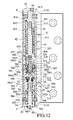
- FIG. 11 is a schematic sectional view taken along line XI-XI in FIG. 10 and illustrating the first embodiment in the initial state;
- FIG. 12 is another schematic sectional view illustrating the first embodiment in an open state
- FIG. 13 illustrates the action of the follower member during the conversion of the first embodiment from the initial state to the open state
- FIG. 14 illustrates the action of the follower member during the conversion of the first embodiment from the open state to the initial state
- FIG. 15 is a schematic top view illustrating the first embodiment in the open state
- FIG. 16 is a schematic sectional view illustrating the first embodiment in the initial state and a mounting bolt of the throttle assembly being moved to an inner-limit position;
- FIG. 17 illustrates the action of the follower member during the conversion of the first embodiment from the initial state to the open state when the mounting bolt of the throttle assembly is at the inner-limit position
- FIG. 18 is a schematic side view illustrating the hinge assemblage according to the disclosure interconnecting first and second objects
- FIG. 19 is a sectional view illustrating a second embodiment of the hinge assemblage according to the disclosure.
- FIG. 20 is a sectional view illustrating a second actuating unit of the second embodiment
- FIG. 21 is a partly exploded perspective view illustrating a third embodiment of the hinge assemblage according to the disclosure.
- FIG. 22 is a sectional view illustrating the third embodiment
- FIG. 23 is a partly exploded perspective view illustrating a fourth embodiment of the hinge assemblage according to the disclosure.
- FIG. 24 is a sectional view illustrating the fourth embodiment
- FIG. 25 is a sectional view illustrating a fifth embodiment of the hinge assemblage according to the disclosure.
- FIG. 26 is an exploded perspective view illustrating a throttle assembly, a one-way valve assembly and a follower member of the fifth embodiment
- FIG. 27 illustrates the action of the follower member during the conversion of the fifth embodiment from the initial state to the open state
- FIG. 28 illustrates the action of the follower member during the conversion of the fifth embodiment from the open state to the initial state
- FIG. 29 is a partly exploded perspective view illustrating a sixth embodiment of the hinge assemblage according to the disclosure.
- FIG. 30 is an exploded perspective view illustrating a damping unit of the sixth embodiment
- FIG. 31 is a schematic sectional view illustrating the sixth embodiment in the open state
- FIG. 32 is another schematic sectional view illustrating the sixth embodiment in the initial state
- FIG. 33 is still another schematic sectional view illustrating the sixth embodiment in the open state.
- FIG. 34 is a sectional view illustrating a seventh embodiment of the hinge assemblage according to the disclosure.
- the first embodiment of the hinge assemblage is for pivotally interconnecting first and second objects 21 , 22 (see FIGS. 15 and 18 ), and includes a leaf mechanism 3 , a first actuating unit 4 and a damping unit 5 .
- the first object 21 may be configured as one of a door and a doorframe
- the second object 22 may be configured as the other one of the door and the doorframe.
- the leaf mechanism 3 includes a first leaf unit 31 .
- the first leaf unit 31 includes a first leaf 311 fixed to the first object 21 , a second leaf 312 fixed to the second object 22 and pivotable relative to said first leaf 311 , a plurality of first barrels 313 fixed to the first leaf 311 , and a plurality of second barrels 314 fixed to the second leaf 312 .
- the first barrels 313 and the second barrels 314 are disposed along an axis (X) in an alternating arrangement.
- An inner surrounding surface of each of the first barrels 313 has two diametrically spaced-apart limiting surface portions 3131 .
- One of the second barrels 314 has two diametrically spaced-apart limiting grooves 3141 that are formed in an inner surrounding surface thereof and that extend in the direction of the axis (X).
- Each of two opposite endmost ones of the first barrels 313 along the axis (X) is formed with two diametrically opposite first threaded through holes 3132 , 3133 (see FIG. 11 ).
- the first actuating unit 4 includes a first tubular member 41 , a connecting axle 42 , a first torque-controlling member 43 , a first torsion spring 44 , a first resilient member 45 and two bolts 46 .
- the first tubular member 41 is inserted into the corresponding first and second barrels 313 , 314 , and is co-rotatable with the first leaf 311 and the first barrels 313 .
- the connecting axle 42 is disposed adjacent to one end of the first tubular member 41 .
- the first torque-controlling member 43 is disposed adjacent to the other end of the first tubular member distal from the connecting axle 42 , and cooperates with the first torsion spring 44 to serve as an actuating module.
- the first tubular member 41 has two diametrically opposite limiting surface portions 411 that respectively abut against the limiting surface portions 3131 of each of the corresponding first barrels 313 , such that the first tubular member 41 is co-rotatable with the first barrels 313 and the first leaf 311 .
- the first tubular member 41 further has a plurality of first engaging teeth 412 that are formed on an inner surface thereof and that surround the axis (X), and two second threaded through holes 413 (see FIG. 11 ) that are respectively registered with the first threaded through holes 3132 of the corresponding first barrel 313 .
- the connecting axle 42 has opposite first and second end portions 421 , 422 that are disposed along the axis (X), a polygonal hole 423 (see FIG. 5 ) that is formed in the first end portion 421 and that extends along the axis (X), and two diametrically spaced-apart protrusions 424 that are formed on an outer surrounding surface of the first end portion 421 .
- the second end portion 422 of the connecting axle 42 extends into the first tubular member 41 .
- the protrusions 424 of the connecting axle 42 respectively engage the limiting grooves 3141 of the one of the second barrels 314 such that the connecting axle 42 is co-rotatable with the second barrels 314 and the second leaf 312 .
- the first torque-controlling member 43 has an insertion hole 431 that extends along the axis (X) and that permits the second end portion 422 of the connecting axle 42 to be inserted thereinto, a plurality of second engaging teeth 432 that are formed on an outer surface thereof and that are removably engaged with the first engaging teeth 412 of the first tubular member 41 , and a coupling groove 433 that is formed in the outer surface thereof and that extends along the axis (X).
- the first and second engaging teeth 412 , 432 are configured such that the first tubular member 41 and the first torque-controlling member 43 are co-rotatable when the first tubular member 41 is rotated in a first rotational direction or when the first torque-controlling member 43 is rotated in a second rotational direction opposite to the first rotational direction, and that the first torque-controlling member 43 is rotatable relative to the first tubular member 41 when the first torque-controlling member 43 is rotated in the first rotational direction.
- the first torsion spring 44 is retained in the first tubular member 41 , surrounds the connecting axle 42 , and has two opposite end sections 441 , 442 that extend along the axis (X).
- the upper end section 441 is co-movably inserted into the coupling groove 433 of the first torque-controlling member 43 .
- the lower end section 442 co-movably abuts against one of the protrusions 424 of the connecting axle 42 .
- the first resilient member 45 is disposed in the insertion hole 431 of the first torque-controlling member 43 , and has two opposite ends respectively abutting against the first torque-controlling member 43 and the second end portion 422 of the connecting axle 42 for resiliently biasing the first torque-controlling member 43 and the connecting axle 42 away from each other.
- Each of the bolts 46 is configured as a set screw, and engages threadably a respective one of the first threaded through holes 3132 of the corresponding first barrel 313 and a corresponding one of the second threaded through holes 413 of the first tubular member 41 to abut against the first torque-controlling member 43 for preventing relative movement between the first tubular member 41 and the first torque-controlling member 43 .
- the damping unit 5 includes an oil tube 51 , a cap assembly 52 , a sleeve member 53 , a first acting member 54 , a second acting member 55 , a follower member 56 , a one-way valve assembly 57 , a second resilient member 58 , a throttle assembly 59 , two pad members 503 , two bolts 504 , a plurality of back-up rings 505 and a plurality of sealing rings 506 .
- the first and second acting members 54 , 55 are disposed fixedly in the oil tube 51 .
- the follower member 56 is partially disposed in the oil tube 51 and between the first and second acting members 54 , 55 , and is movable relative to the oil tube 51 .
- the follower member 56 cooperates with the first acting member 54 to define a first oil chamber 501 therebetween, and cooperates with the second acting member 55 to define a second oil chamber 501 therebetween.
- the first and second oil chambers 501 , 502 are filled with oil.
- the one-way valve assembly 57 and the throttle assembly 59 cooperatively serve as a hydraulic module.
- An outer surface of the oil tube 51 has two diametrically opposite limiting surface portions 511 that respectively abut against the limiting surface portions 3131 of each of the corresponding first barrels 313 , such that the oil tube 51 is co-rotatable with the first barrels 313 and the first leaf 311 .
- the oil tube 51 further has two diametrically opposite first positioning grooves 512 that are formed in an inner surface thereof and that are proximate to one of two opposite longitudinal ends thereof, two diametrically opposite second positioning grooves 513 that are formed in the inner surface thereof and that are proximate to the other one of the two opposite longitudinal ends thereof, and two third threaded through holes 514 (see FIG. 11 ) that are respectively registered with the first threaded through holes 3133 of the corresponding first barrel 313 .
- the first acting member 54 has an inclined cam surface 541 that faces toward the second acting member 55 , and two positioning protrusions 542 that are formed on an outer surface thereof and that respectively engage the first positioning grooves 512 of the oil tube 51 so that the first acting member 54 is fixedly positioned in the oil tube 51 .
- the second acting member 55 has an inclined cam surface 551 that faces toward the first acting member 54 , and two positioning protrusions 552 that are formed on an outer surface thereof and that respectively engage the second positioning grooves 513 of the oil tube 51 so that the second acting member 55 is fixedly positioned in the oil tube 51 .
- the follower member 56 has a main body 560 that has opposite first and second abutment surfaces 561 , 562 respectively facing toward the cam surfaces 541 , 551 of the first and second acting members 54 , 55 , a polygonal rod section 563 that extends away from the second acting member 54 , through the first acting member 54 and out of the oil tube 51 , a communicating passage 564 that extends along the axis (X) and through the main body 560 and the polygonal rod section 563 , and a communicating hole 565 that is formed in the polygonal rod section 563 and that fluidly communicates with the communicating passage 564 and the first oil chamber 501 .
- the polygonal rod section 563 is inserted into the polygonal hole 423 of the connecting axle 42 of the first actuating unit 4 in such a manner that the follower member 56 is co-rotatable with the connecting axle 42 about the axis (X) and is movable relative to the connecting axle 42 along the axis (X).
- the communicating passage 564 has a first end opening 5641 that is proximate to the second acting member 55 , and a second end opening 5642 that is opposite to the first end opening 5641 and that is proximate to the connecting axle 42 .
- the follower member 56 further has an inner threaded portion 5643 that is proximate to the second end opening 5642 .
- the cap assembly 52 and the sleeve member 53 are respectively threaded to the two opposite longitudinal ends of the oil tube 51 .
- the sleeve member 53 has two through holes 531 that are respectively registered with the third threaded through holes 514 of the oil tube 51 .
- the cap assembly 52 includes a cap body 521 that is threaded to the oil tube 51 and that permits the polygonal rod section 563 of the follower member 56 to extend therethrough, a plurality of back-up rings 522 that are sleeved between the cap body 521 and the polygonal rod section 563 of the follower member 56 , and a sealing ring 523 that is sleeved on the follower member 56 between the cap body 521 and the polygonal rod section 563 of the follower member 56 and that is forcibly clamped between the back-up rings 522 for air-tightly sealing a gap between the cap body 521 and the polygonal rod section 563 of the follower member 56 .
- the one-way valve assembly 57 is disposed in the main body 560 of the follower member 56 , and includes a valve seat 571 , two oil passages 572 each extending in the direction of the axis (X) through the valve seat 571 and fluidly communicating with the communicating passage 564 and the second oil chamber 502 , two valve members 573 each being disposed in a respective one of the oil passages 572 for removably blocking the corresponding oil passage 572 , two oil resilient members 574 each being disposed in a respective one of the oil passages 572 for resiliently biasing the corresponding valve member 573 toward the first oil chamber 501 so as to block the corresponding oil passage 572 , and an extension hole 575 extending along the axis (X) through the valve seat 571 .
- a middle portion of the extension hole 575 has an inner diameter smaller than that of each of two opposite longitudinal end portions of the extension hole 575 .
- the second resilient member 58 is disposed in the oil tube 51 , and has two opposite ends respectively abutting against the second acting member 55 and the follower member 56 .
- the throttle assembly 59 extends along the axis (X) through the sleeve member 53 , the second acting member 55 , the follower member 56 and the one-way valve assembly 57 , and includes a mounting bolt 591 , a needle 592 , a pin resilient member 593 , a pin 594 , a sleeve piece 595 , a sealing ring 596 and a securing member 597 .
- the mounting bolt 591 extends along the axis (X) through the second acting member 55 and the sleeve member 53 , engages threadably the sleeve member 53 , and has a hexagonal hole 5911 formed in an end thereof and exposed out of the sleeve member 53 .
- the needle 592 extends along the axis (X) through the extension hole 575 of the one-way valve assembly 57 , and has a first end portion 5921 that is rotatably mounted to the mounting bolt 591 , a second end portion 5923 that is opposite to the first end portion 5921 and that extends into the polygonal rod section 563 of the follower member 56 , a channel 5922 that is formed in the second end portion 5923 and that is defined by a channel-defining surface, an outer shoulder surface 5924 that is formed on the first end portion 5921 , two annular clinging surfaces 5927 that are formed on an outer surrounding surface of the second end portion 5923 , that are spaced apart from each other along the axis (X), and that fluid-tightly cling to an inner surface of the polygonal rod section 563 of the follower member 56 , a first communicating hole 5925 that is formed in the second end portion 5923 and that fluidly communicates with the channel 5922 and a
- the pin 594 extends along the axis (X), is inserted into the polygonal rod section 563 of the follower member 56 and the channel 5922 of the needle 592 , and cooperates with the channel-defining surface of the needle 5922 to define an oil space 5940 therebetween.
- the pin 594 has a conical section (I) that tapers toward the second acting member 55 and that has a tapered annular surface 5941 , a head section 5942 that is distal from the second acting member 55 and that is threadedly secured to the polygonal rod section 563 , and a hexagonal hole 5943 (see FIG. 9 ) that is formed in the head section 5942 .
- the sleeve piece 595 is sleeved on the needle 592 , abuts against the mounting bolt 591 and the outer shoulder surface 5924 of the needle 592 , and has a rounded head portion 5951 that is formed at one end thereof proximate to the outer shoulder surface 5924 of the needle 592 .
- the sleeve piece 595 has an outer diameter greater than that of a segment of the first end portion 5921 distal from the mounting bolt 591 .
- the securing member 597 is threaded to the inner threaded portion 5643 of the follower member 56 , and has a hexagonal hole 5971 (see FIG. 9 ) that is exposed out of the follower member 56 .
- the sealing ring 596 is sleeved on the securing member 597 , and fluid-tightly seals a gap between the securing member 597 and the polygonal rod section 563 of the follower member 56 so as to fluid-tightly block the second end opening 5642 of the communicating passage 564 .
- the pad members 503 are respectively disposed in the through holes 531 of the sleeve member 53 .
- Each of the bolts 504 is configured as a set screw, and engages threadably a respective one of the first threaded through holes 3133 of the corresponding first barrel 313 and a corresponding one of the third threaded through holes 514 of the oil tube 51 to press the corresponding pad member 503 against the mounting bolt 591 for preventing relative movement between the oil tube 51 , the sleeve member 53 and the mounting bolt 591 .
- the sealing rings 506 are respectively and fluid-tightly disposed between the mounting bolt 591 and the sleeve member 53 , between the first acting member 54 and the oil tube 51 , between the second acting member 55 and the oil tube 51 , between the follower member 56 and the oil tube 51 , between the first acting member 54 and the polygonal rod section 563 of the follower member 56 , and between the second acting member 55 and the mounting bolt 591 .
- the back-up rings 505 are disposed between the first acting member 54 and the polygonal rod section 563 of the follower member 56 to forcibly press a corresponding sealing ring 506 , and between the second acting member 55 and the mounting bolt 591 to forcibly press against another corresponding sealing ring 506 .
- the one-way valve assembly 57 is first mounted in the communicating passage 564 of the follower member 56 at a position adjacent to the first end opening 5641 , and the pin 594 and the sealing ring 596 are installed into the polygonal rod section 563 via the second end opening 5642 . Then, the securing member 597 is threaded to the inner threaded portion 5643 of the follower member 56 to position the pin 594 and the sealing ring 596 within the polygonal rod section 563 .
- the pin resilient member 593 , the needle 592 , the sleeve piece 595 and the mounting bolt 591 are sequentially installed into the oil tube 51 in such a manner that the pin 594 is inserted into the channel 5922 of the needle 592 and that the pin resilient member 593 is disposed in the polygonal rod section 563 and has two opposite ends that respective abut against the needle 592 and an inner surface of the rod section 563 .
- the needle 592 is moved relative to the pin 594 when the mounting bolt 591 is turned to move relative to the sleeve member 53 .
- an oil passageway is defined from the first end opening 5641 of the communicating passage 564 , via a gap between the sleeve piece 595 and the valve seat 571 , a gap between the needle 592 and the valve seat 571 , the second communicating holes 5926 , the oil space 5940 , a gap defined between the pin 594 and an inner surrounding surface of the needle 592 and corresponding in position to the first communicating hole 5925 , the first communicating hole 5925 , the space defined between the annular clinging surfaces 5927 , to the communicating hole 565 of the follower member 56 for fluid communication between the first and second oil chambers 501 , 502 .
- Each of the oil passages 572 is in spatial communication with the second oil chamber 502 and the gap between the needle 592 and the valve seat 571 .
- the mounting bolt 591 is turned by a tool (not shown) to move relative to the sleeve member 53 along the axis (X)
- the needle 592 is thereby moved relative to the pin 594 so as to adjust the volume of the oil space 5940 .
- the first tubular member 41 and the first torque-controlling member 43 are configured to be co-rotatable by virtue of the engagement between the first and second engaging teeth 412 , 432 when the hinge assemblage is converted from the initial state to the open state. Since the end sections 441 , 442 of the first torsion spring 44 respectively co-movably engage the coupling groove 433 of the first torque-controlling member 43 and one of the protrusions 424 of the connecting axle 42 , the first torsion spring 44 is deformed to exert an actuating force, so as to generate a resultant restoring torque in response to the conversion of the hinge assemblage from the initial state to the open state.
- the cam surface 551 of the second acting member 55 is configured to push the second abutment surface 562 of the follower member 56 to move the follower member 56 relative to the oil tube 51 toward the first acting member 54 and away from the second acting member 55 in response to the conversion of the hinge assemblage from the initial state to the open state, so as to compress the first oil chamber 501 .
- the oil in the first oil chamber 501 flows through the communicating hole 565 of the follower member 56 , the space defined between the annular clinging surfaces 5927 , the first communicating hole 5925 , the gap between the pin 594 and the inner surrounding surface of the needle 592 , the oil space 5940 , the second communicating holes 5926 into the gap between the needle 592 and the valve seat 571 , and then flows into the second oil chamber 502 via the oil passages 572 of the one-way valve assembly 57 and via the gap between the sleeve piece 595 and the valve seat 571 and the first end opening 5641 of the communicating passage 564 .
- the oil flowing from the gap between the needle 592 and the valve seat 571 through the oil passages 572 of the one-way valve assembly 57 pushes the valve members 573 against the biasing action of the oil resilient members 574 so as to unblock the oil passages 572 .
- the pin 594 is moved relative to the needle 592 so as to enlarge the gap defined between the pin 594 and the inner surrounding surface of the needle 592 (i.e., the channel-defining surface) and corresponding in position to the first communicating hole 5925 .
- the gap defined between the pin 594 and the inner surrounding surface of the needle 592 and corresponding in position to the first communicating hole 5925 is relatively small, so that a damping force generated by the hydraulic module is relatively large.
- the gap defined between the pin 594 and the inner surrounding surface of the needle 592 and corresponding in position to the first communicating hole 5925 is enlarged due to the increase of the angle between the first and second leaves 311 , 312 , the damping force generated by the hydraulic module becomes relatively small.
- the restoring torque generated by the first torsion spring 44 pivots the connecting axle 42 and the first torque-controlling member 43 relative to each other so as to convert the hinge assemblage from the open state to the initial state.
- the cam surface 541 of the first acting member 54 pushes the first abutment surface 561 of the follower member 56 to move the follower member 56 relative to the oil tube 51 toward the second acting member 55 and away from the first acting member 54 in response to the conversion of the hinge assemblage from the open state to the initial state, so as to compress the second oil chamber 502 .
- the oil flowing from the second oil chamber 502 into the oil passages 572 of the one-way valve assembly 57 pushes the valve members 573 against the valve seat 571 so as to block the oil passages 572 , so that the oil in the second oil chamber 502 is only permitted to flow into the first oil chamber 501 via the aforesaid oil passageway that is defined from the first end opening 5641 of the communicating passage 564 , via the gap between the sleeve piece 595 and the valve seat 571 , the gap between the needle 592 and the valve seat 571 , the second communicating holes 5926 , the oil space 5940 , a gap between the pin 594 and the inner surrounding surface of the needle 592 , the first communicating hole 5925 , the space defined between the annular clinging surfaces 5927 , to the communicating hole 565 of the follower member 56 .
- the damping force generated by the hydraulic module during the conversion of the hinge assemblage from the open state to the initial state is greater than the damp
- the valve seat 571 is moved toward the sleeve piece 595 so as to narrow the gap between the sleeve piece 595 and the valve seat 571 , and the pin 594 is moved relative to the needle 592 so as to narrow the gap defined between the pin 594 and the inner surrounding surface of the needle 592 and corresponding in position to the first communicating hole 5925 , so that the damping force generated by the hydraulic module becomes even greater.
- the first leaf unit 31 , the first actuating unit 4 and the damping unit 5 cooperatively form a first hinge assembly 100 .
- a plurality of the first hinge assemblies 100 may be connected between the first and second objects 21 , 22 .
- the damping unit 5 generates a relatively small damping force so as to facilitate the conversion of the first and second objects 21 , 22 to a state illustrated in FIG. 15 , and generates a much greater damping force when the angle between the first and second leaves 311 , 312 is nearly 0 degree so as to prevent severe collision between the first and second objects 21 , 22 .
- the first torque-controlling member 43 can be rotated in the first rotational direction relative to the first tubular member 41 by a tool (not shown) to adjust the relative position between the first and second engaging teeth 412 , 432 so as to adjust the magnitude of the resultant restoring torque generated by the first torsion spring 44 for collaborating with the damping unit 5 .
- the mounting bolt 591 can be turned by a tool (not shown) to move the needle 592 relative to the polygonal rod section 563 of the follower member 56 along the axis (X) to adjust the gap between the sleeve piece 595 and the valve seat 571 and the gap defined between the pin 594 and the inner surrounding surface of the needle 592 and corresponding in position to the first communicating hole 5925 , so as to adjust the damping force generated by the damping unit 5 during the conversion of the hinge assemblage between the open state and the initial state.
- the mounting bolt 591 can be turned to move to an inner-limit position relative to the follower member 56 such that the sleeve piece 595 is substantially retained in the valve seat 571 of the one-way valve 57 to considerably narrow the gap between the sleeve piece 595 and the valve seat 571 and the gap defined between the pin 594 and the inner surrounding surface of the needle 592 and corresponding in position to the first communicating hole 5925 , so that the first and second leaves 311 , 312 are difficult to be pivoted relative to each other.
- the hinge assemblage can be maintained in the open state when the external forces are removed for repair or other demands.
- the damping force generated by the damping unit becomes rather small such that the first and second leaves 311 , 312 are easy to be pivoted relative to each other.
- the second embodiment of the hinge assemblage includes a leaf mechanism 3 , a damping unit 5 and a second actuating unit 6 .
- the leaf mechanism 3 and the damping unit 5 of the second embodiment are similar to that of the first embodiment.
- the second actuating unit 6 includes a second tubular member 61 that is inserted into the corresponding first and second barrels 313 , 314 and that is co-rotatable with the first leaf 311 and the first barrels 313 , a connecting axle 68 that extends into the second tubular member 61 and that is rotatable relative to the second tubular member 61 , a friction member 64 that is connected fixedly to the second tubular member 61 , a slide sleeve 63 that is co-rotatably sleeved on the connecting axle 68 , a spring washer assembly 62 that is disposed in the second tubular member 61 and that pushes the slide sleeve 63 against the friction member 64 , a brake-conditioning member 65 that engages threadably the second tubular member 61 and that pushes the spring washer assembly 62 against the slide sleeve 63 , two pad members 66 and two bolts 67 .
- the second tubular member 61 has two second threaded through holes 611 that are respectively registered with the first threaded through holes 3132 of the corresponding first barrel 313 .
- a frictional force generated between the slide sleeve 63 and the friction member 64 serves as an actuating force for condition of the speed of the relative pivotal movement between the first and second leaves 311 , 312 .
- the pad members 66 are respectively disposed in the second threaded through holes 611 of the second tubular member 61 .
- Each of the bolts 67 engages threadably a respective one of the first threaded through holes 3132 of the corresponding first barrel 313 and a corresponding one of the second threaded through holes 611 of the second tubular member 61 to press the corresponding pad member 66 against the brake-conditioning member 65 for preventing relative movement between the brake-conditioning member 65 and the second tubular member 61 .
- the connecting axle 68 extends through the slide sleeve 63 and the friction member 64 , engages the limiting grooves 3141 (see FIG.
- the first leaf unit 31 , the second actuating unit 6 and the damping unit 5 cooperatively form a first hinge assembly 100 .
- the damping unit 5 generates a relatively small damping force so as to facilitate the conversion of the first and second objects 21 , 22 to the state illustrated in FIG. 15 .
- the frictional force generated between the slide sleeve 63 and the friction member 64 serves as an actuating force that retards the relative rotation between the follower member 56 and the oil tube 51 , so as to condition the speed of the relative pivotal movement between the first and second leaves 311 , 312 .
- the brake-conditioning member 65 can be turned by a tool (not shown) to move relative to the second tubular member 61 to adjust the biasing force exerted by the spring washer assembly 62 so as to adjust the frictional force generated between the slide sleeve 63 and the friction member 64 during the conversion of the hinge assemblage between the open state and the initial state.
- the third embodiment of the hinge assemblage includes a first hinge assembly 100 (see FIG. 11 or 20 ) and two additional first actuating units 4 , 4 ′.
- the leaf mechanism 3 of the third embodiment further includes a second leaf unit 32 .
- the second leaf unit 32 and the additional first actuating units 4 , 4 ′ cooperatively form a second hinge assembly 200 .
- the second leaf unit 32 is similar to the first leaf unit 31 , and includes a first leaf 321 fixed to the first object 21 , a second leaf 322 fixed to the second object 22 , a plurality of first barrels 323 fixed to the first leaf 321 , and a plurality of second barrels 324 fixed to the second leaf 322 .
- the first barrels 323 and the second barrels 324 are disposed along an axis (X) in an alternating arrangement.
- the additional first actuating units 4 , 4 ′ are inserted into the first and second barrels 323 , 324 .
- the first tubular members 41 of the additional first actuating units 4 , 4 ′ are co-rotatable with the first barrels 323 and the first leaf 321 .
- the first end portions 421 , 421 ′ of the connecting axles 42 , 42 ′ of the additional first actuating units 4 , 4 ′ are co-rotatably interengaged, so that the connecting axles 42 , 42 ′ are co-rotatable with the second barrels 324 and the second leaf 322 .
- the first torsion springs 44 , 44 ′ of the additional first actuating units 4 , 4 ′ are respectively configured as right-hand and left-hand coil springs.
- each of the first torsion springs 44 , 44 ′ of the additional first actuating units 4 , 4 ′ is deformed to exert an actuating force. Therefore, the second hinge assembly 200 is able to provide a resultant restoring torque two times the restoring torque provided by the first hinge assembly 100 in FIG. 11 .
- the fourth embodiment of the hinge assemblage includes a first hinge assembly 100 (see FIG. 11 or 20 ), an additional first actuating unit 4 and an additional second actuating unit 6 .
- the leaf mechanism 3 of the fourth embodiment further includes a third leaf unit 33 .
- the third leaf unit 33 and the additional first and second actuating units 4 , 6 cooperatively form a third hinge assembly 300 .
- the third leaf unit 33 is similar to the first leaf unit 31 , and includes a first leaf 331 fixed to the first object 21 , a second leaf 332 fixed to the second object 22 , a plurality of first barrels 333 fixed to the first leaf 331 , and a plurality of second barrels 334 fixed to the second leaf 332 .
- the first barrels 333 and the second barrels 334 are disposed along an axis (X) in an alternating arrangement.
- the additional first actuating unit 4 is inserted into the corresponding first and second barrels 333 , 334 .
- the first tubular member 41 of the additional first actuating unit 4 is co-rotatable with the first leaf 331 and the first barrels 333 .
- the connecting axle 42 of the additional first actuating unit 4 is co-rotatable with the second leaf 332 and the second barrels 334 .
- the second tubular member 61 of the additional second actuating unit 6 is inserted into the corresponding first and second barrels 333 , 334 , and is co-rotatable with the first leaf 331 and the first barrels 333 .
- the connecting axle 68 of the additional second actuating unit 6 extends through the friction member 64 and the slide sleeve 63 to engage the first end portion 421 of the connecting axle 42 of the additional first actuating unit 4 , and is co-rotatable with the connecting axle 42 and the slide sleeve 63 about the axis (X).
- the first torsion springs 44 of the additional first actuating unit 4 is deformed to exert an actuating force so as to generate a resultant restoring torque.
- the spring washer assembly 62 pushes the slide sleeve 63 against the friction member 64 to generate a frictional force between the slide sleeve 63 and the friction member 64 that serves as another actuating force for retarding the relative rotation between the first tubular member 41 and the connecting axle 42 of the additional first actuating unit 4 , so as to condition the speed of the relative pivotal movement between the first and second leaves 311 , 312 .
- the hinge assemblage of this disclosure may include any number of the first, second and third hinge assembles 100 , 200 , 300 so as to pivotally interconnect the first and second objects 21 , 22 .
- the fifth embodiment of the hinge assemblage is similar to the first embodiment, and includes a leaf mechanism 3 , a first actuating unit 4 and a damping unit 5 .
- the damping unit 5 further includes a one-way valve assembly 57 ′ and a throttle assembly 7 to respectively substitute the one-way valve assembly 57 and the throttle assembly 59 of the first embodiment (see FIG. 3 ).
- the follower member 56 further has an oil path 566 that is formed through the main body 560 and that fluidly communicates with the first and second oil chambers 501 , 502 , an oil groove 567 that is formed in the inner surface of the follower member 56 and that fluidly communicates with the second oil chamber 502 , and two communicating holes 565 that are formed in the polygonal rod section 563 and that fluidly communicate with the communicating passage 564 formed therethrough and the first oil chamber 501 .
- the one-way valve assembly 57 ′ includes a valve member 576 , an annular gasket 577 and a positioning ring 578 .
- the valve member 576 may be configured as a plate, a bolt or a ball.
- the positioning ring 578 positions the annular gasket 577 relative to the follower member 56 , such that the valve member 576 is permitted to move within a space defined between the follower member 56 and the annular gasket 577 for removably blocking the oil path 566 .
- the throttle assembly 7 extends along the axis (X) through the sleeve member 53 , the second acting member 55 , the follower member 56 and the one-way valve assembly 57 ′, and includes a mounting bolt 71 , a first needle 72 , a second needle 73 , a pin 74 , a securing member 75 , two back-up rings 76 and a sealing ring 77 .
- the mounting bolt 71 extends along the axis (X) through the second acting member 55 and the sleeve member 53 , and engages threadably the sleeve member 53 .
- the first needle 72 is movably mounted to the mounting bolt 71 and extends along the axis (X) into the follower member 56 .
- the second needle 73 is disposed in the communicating passage 564 of the follower member 56 , and is threaded to the first needle 72 .
- the pin 74 is threaded to the second needle 73 .
- the securing member 75 is threaded to the inner threaded portion 5643 of the follower member 56 .
- the back-up rings 76 are disposed between the first and second needles 72 , 73 .
- the sealing ring 77 is forcibly clamped between the back-up rings 76 for air-tight contact with the inner surface of the follower member 56 .
- the follower member 56 and the throttle assembly 7 are configured such that the fluid communication between the oil groove 567 and one of the communicating holes 565 proximate to the oil groove 567 is permitted so as to form an oil passageway when the one of the communicating holes 565 corresponds in position to the back-up rings 76 and the sealing ring 77 , and the fluid communication between the oil groove 567 and the one of the communicating holes 565 is blocked when the one of the communicating holes 565 corresponds in position to an outer surrounding surface of the second needle 73 .
- the one-way valve assembly 57 ′ and the throttle assembly 7 cooperatively serve as a hydraulic module.
- the follower member 56 When external forces are applied to pivot the first and second leaves 311 , 312 relative to each other such that the hinge assemblage is converted from the initial state to the open state, the follower member 56 is pushed by the cam surface 551 of the second acting member 55 to compress the first oil chamber 501 .
- the oil in the first oil chamber 501 flows into the second oil chamber 502 via the oil path 566 and via the one of the communicating holes 565 and the oil groove 567 until the one of the communicating holes 565 corresponds in position to the outer surrounding surface of the second needle 73 .
- the oil flowing from the first oil chamber 501 and through the oil path 566 pushes the valve member 576 so as to unblock the oil path 566 .
- the cam surface 541 of the first acting member 54 pushes the follower member 56 toward the second acting member 55 so as to compress the second oil chamber 502 .
- the oil in the second oil chamber 502 is prevented from flowing into the oil path 566 by the valve member 576 , and is only permitted to flow into the first oil chamber 501 via the oil groove 567 and the one of the communicating holes 565 corresponds in position to the back-up rings 76 and the sealing ring 77 .
- the damping force generated by the hydraulic module during the conversion of the hinge assemblage from the open state to the initial state is greater than the damping force generated by the hydraulic module during the conversion of the hinge assemblage from the initial state to the open state.
- the mounting bolt 71 can be turned to move relative to the follower member 56 so as to move the back-up rings 76 and the sealing ring 77 to correspond in position to the one of the communicating holes 565 , and to permit the fluid communication between the oil groove 567 and the one of the communicating holes 565 .
- the sixth embodiment of the hinge assemblage includes a leaf mechanism 3 that includes a first leaf unit 31 , a second actuating unit 6 and a damping unit 8 .
- the damping unit 8 includes an oil tube 81 , a first acting member 82 , a hydraulic module 83 , a follower member 84 , a spacing block 85 , an oil spring 86 , a cap 87 and a washer 88 .
- the oil tube 81 is inserted into the corresponding first and second barrels 313 , 314 , and has two diametrically opposite limiting surface portions 811 that are formed on an outer surface thereof, and that respectively abut against the limiting surface portions 3131 of each of the corresponding first barrels 313 , such that the oil tube 81 is co-rotatable with the first barrels 313 and the first leaf 311 .
- the first acting member 82 is disposed fixedly in the oil tube 81 , and has an inclined cam surface 821 .
- the hydraulic module 83 includes a main body 831 that is movably threaded within the oil tube 81 , a sleeve 832 that is connected fixedly to an end of the main body 831 distal from the first acting member 82 , and an adjusting bolt 833 that engages threadably the sleeve 832 .
- the main body 831 has a protrusion 8311 that protrudes toward the first acting member 82 for being depressed, such that the main body 831 generates a damping force upon the depression of the protrusion 8311 .
- the sleeve 832 is for being operated to move the main body 831 relative to the oil tube 81 , so as to adjust a distance between the protrusion 8311 and the first acting member 82 .
- the adjusting bolt 833 can be turned by a tool (not shown) to move relative to the sleeve 832 , so as to adjust the damping coefficient of the main body 831 to adjust the magnitude of the damping force generated by the main body 831 upon the depression of the protrusion 8311 .
- the follower member 84 is movable relative to the oil tube 81 along the axis (X), and has a main body 840 that is disposed between the first acting member 82 and the hydraulic module 83 and that has an abutment surface 841 facing toward the cam surface 821 of the first acting member 82 , and a polygonal rod section 842 that extends out of the oil tube 81 through the first acting member 82 , and that is coupled to the connecting axle 68 of the second actuating unit 6 in such a manner that the polygonal rod section 842 and the connecting axle 68 are co-rotatable about the axis (X), and are movable relative to each other along the axis (X). Therefore, the follower member 84 is co-rotatable with the second barrels 314 about the axis (X).
- the spacing block 85 is connected fixedly to the follower member 84 for depressing the protrusion 8311 of the hydraulic module 83 upon the movement of the follower member 84 relative to the oil tube 81 .
- the oil spring 86 resiliently biases the follower member 84 toward the first acting member 82 .
- the cap 87 is mounted to an end of the oil tube 81 distal from the first acting member 82 .
- the washer 88 has opposite ends respectively abutting against the main body 831 of the hydraulic module 83 and the oil spring 86 .
- the cam surface 821 of the first acting member 82 pushes the abutment surface 841 of the follower member 84 so as to move the follower member 84 toward the protrusion 8311 of the hydraulic module 83 .
- the first acting member 82 is rotated relative to the follower member 84 so as to permit the follower member 84 to be moved away from the hydraulic module 83 by the oil spring 86 . Therefore, the hydraulic module 83 is for damping the movement of the follower member 84 when the hinge assemblage is converted from the open state to the initial state, and would not damp the movement of the follower member 84 away from the hydraulic module 83 .
- the sleeve 832 can be turned by a tool (not shown) to move the main body 831 toward the spacing block 85 , so that the spacing block 85 and the protrusion 8311 are in contact when the first and second leaves 311 , 312 are rotated to form a predetermined angle therebetween.
- the follower member 84 may move the spacing block 85 to depress the protrusion 8311 so that the main body 831 generates a damping force for preventing severe collision between the first and second objects 21 , 22 when the angle between the first and second leaves 311 , 312 is nearly 0 degree (see FIG. 32 ), or when the angle between the first and second leaves 311 , 312 is nearly 90 degrees (see FIG. 33 ).
- the first acting member 82 and the follower member 84 may be configured such that the cam surface 821 of the first acting member 82 pushes the abutment surface 841 of the follower member 84 so as to move the follower member 84 toward the protrusion 8311 of the hydraulic module 83 when the hinge assemblage is converted from the initial state to the open state, and that the first acting member 82 is rotated relative to the follower member 84 so as to permit the follower member 84 to be moved away from the hydraulic module 83 by the oil spring 86 when the hinge assemblage is converted from the open state to the initial state. Therefore, the hydraulic module 83 is for damping the movement of the follower member 84 when the hinge assemblage is converted from the initial state to the open state.
- the seventh embodiment of the hinge assemblage according to the disclosure is similar to the first embodiment, and further includes a damping unit 8 to substitute the damping unit 5 (see FIG. 3 ).
- the leaf units 31 , 32 , 33 , the hydraulic units 5 , 8 and the first and second actuating units 4 , 6 of this disclosure are modularized, so that a user can construct a hinge assembly according to particular demand by selecting and assembling suitable ones of the aforesaid units.
- first and second leaves of the leaf units 31 , 32 , 33 are 0 degree when the hinge assemblage is at the initial state, the hinge assemblage can only be converted from the initial state. Therefore, whether the first and second objects 21 , 22 constitute a right-handed door or a left-handed door, a user can install the hinge assemblage of the disclosure between the first and second objects 21 , 22 without confusion.
- Each of the hydraulic units 5 , 8 of this disclosure generates different damping forces in response to the movement of the follower member 56 , 84 thereof in different directions. Therefore, the hinge assemblage of this disclosure is subjected to different damping forces when it is converted from the initial state to the open state and when it is converted from the open state to the initial state.
- Each of the hydraulic units 5 , 8 and the first and second actuating units 4 , 6 of this disclosure can be manually adjusted without disassembling the corresponding hinge assembly 100 , 200 , 300 . Therefore, the characteristic of the hinge assembly 100 , 200 , 300 can be easily adjusted.
Landscapes
- Engineering & Computer Science (AREA)
- Mechanical Engineering (AREA)
- Vehicle Body Suspensions (AREA)
Abstract
Description
Claims (24)
Priority Applications (1)
| Application Number | Priority Date | Filing Date | Title |
|---|---|---|---|
| US15/150,475 US9617772B1 (en) | 2016-05-10 | 2016-05-10 | Hinge assemblage |
Applications Claiming Priority (1)
| Application Number | Priority Date | Filing Date | Title |
|---|---|---|---|
| US15/150,475 US9617772B1 (en) | 2016-05-10 | 2016-05-10 | Hinge assemblage |
Publications (1)
| Publication Number | Publication Date |
|---|---|
| US9617772B1 true US9617772B1 (en) | 2017-04-11 |
Family
ID=58461719
Family Applications (1)
| Application Number | Title | Priority Date | Filing Date |
|---|---|---|---|
| US15/150,475 Active US9617772B1 (en) | 2016-05-10 | 2016-05-10 | Hinge assemblage |
Country Status (1)
| Country | Link |
|---|---|
| US (1) | US9617772B1 (en) |
Cited By (18)
| Publication number | Priority date | Publication date | Assignee | Title |
|---|---|---|---|---|
| CN108343333A (en) * | 2018-03-09 | 2018-07-31 | 温州职业技术学院 | A kind of hydraulic hinge |
| US20190106921A1 (en) * | 2017-10-05 | 2019-04-11 | Kason Industries, Inc. | Door closer |
| US10280669B2 (en) * | 2017-10-05 | 2019-05-07 | Kason Industries, Inc. | Door closer |
| RU2692749C1 (en) * | 2018-12-13 | 2019-06-27 | Уотерсон Корп. | Loop |
| CN110811400A (en) * | 2018-08-07 | 2020-02-21 | 加藤电机(香港)有限公司 | Damping hinge and Western toilet using this damping hinge |
| CN111088921A (en) * | 2018-10-23 | 2020-05-01 | 日本电产三协(浙江)有限公司 | Hinge and refrigerator-freezer |
| US20200190884A1 (en) * | 2018-12-12 | 2020-06-18 | Waterson Corp. | Hinge |
| US11008794B2 (en) | 2019-05-27 | 2021-05-18 | Waterson Chen | Damper device and hinge assembly including the same |
| US11067156B1 (en) * | 2020-07-21 | 2021-07-20 | Hi-Lex Controls, Inc. | Friction brake and power strut therewith |
| US20210363805A1 (en) * | 2020-05-20 | 2021-11-25 | Kason Industries, Inc. | Pivot hinge |
| US20210363804A1 (en) * | 2020-05-20 | 2021-11-25 | Kason Industries, Inc. | Pivot hinge |
| US20230056621A1 (en) * | 2021-08-18 | 2023-02-23 | United States Bullet Proofing, Inc. | Hinge assembly for a security door |
| US20230304344A1 (en) * | 2022-03-23 | 2023-09-28 | Moshun, LLC | Systems and devices for motion control |
| CN117919583A (en) * | 2024-03-15 | 2024-04-26 | 潍坊市华星医疗器械有限公司 | Reusable adjusting device for flow of infusion apparatus with needle |
| US20240254819A1 (en) * | 2023-01-30 | 2024-08-01 | Andersen Corporation | Adjustable self-closing door hinge and door systems incorporating the hinges |
| US20240426156A1 (en) * | 2021-08-30 | 2024-12-26 | Locinox | A hydraulically damped hinge and a method of assembling the same |
| WO2025077559A1 (en) * | 2023-10-12 | 2025-04-17 | 杭州安费诺飞凤通信部品有限公司 | Variable-damping-torque rotating shaft mechanism |
| US12546375B2 (en) | 2021-01-08 | 2026-02-10 | Moshun, LLC | Systems and devices for motion control |
Citations (11)
| Publication number | Priority date | Publication date | Assignee | Title |
|---|---|---|---|---|
| US1824217A (en) * | 1929-06-13 | 1931-09-22 | Kreiner Friedrich | Door hinge |
| US3074101A (en) * | 1958-11-22 | 1963-01-22 | Hideyoshi Hiroaki | Door check |
| US5031270A (en) * | 1990-03-15 | 1991-07-16 | Simpson Lee | Friction hinge |
| US5152029A (en) * | 1991-08-12 | 1992-10-06 | King Chain Precision Industry Co., Ltd. | Hydraulic hinge |
| US5195210A (en) * | 1992-06-19 | 1993-03-23 | Simpson Lee | Hydraulic door hinge |
| US5219372A (en) * | 1992-06-18 | 1993-06-15 | Simpson Lee | Door accessory with a hydraulic retarding device |
| US5572768A (en) * | 1994-04-13 | 1996-11-12 | Enidine Incorporated | Door closer |
| US5855040A (en) * | 1997-03-31 | 1999-01-05 | Dawnwell Int'l Co., Ltd. | Hinge structure of rotary door |
| US6658694B2 (en) * | 2002-03-07 | 2003-12-09 | Fu Luong Hi-Tech Co., Ltd | Hinge device with a returning member for automatically closing an open door |
| US7966693B2 (en) * | 2006-08-08 | 2011-06-28 | I-One Innotech Co., Ltd | Hinge apparatus having automatic return function |
| US8683654B2 (en) * | 2010-08-05 | 2014-04-01 | Waterson Corp. | Adjustable torque hinge |
-
2016
- 2016-05-10 US US15/150,475 patent/US9617772B1/en active Active
Patent Citations (11)
| Publication number | Priority date | Publication date | Assignee | Title |
|---|---|---|---|---|
| US1824217A (en) * | 1929-06-13 | 1931-09-22 | Kreiner Friedrich | Door hinge |
| US3074101A (en) * | 1958-11-22 | 1963-01-22 | Hideyoshi Hiroaki | Door check |
| US5031270A (en) * | 1990-03-15 | 1991-07-16 | Simpson Lee | Friction hinge |
| US5152029A (en) * | 1991-08-12 | 1992-10-06 | King Chain Precision Industry Co., Ltd. | Hydraulic hinge |
| US5219372A (en) * | 1992-06-18 | 1993-06-15 | Simpson Lee | Door accessory with a hydraulic retarding device |
| US5195210A (en) * | 1992-06-19 | 1993-03-23 | Simpson Lee | Hydraulic door hinge |
| US5572768A (en) * | 1994-04-13 | 1996-11-12 | Enidine Incorporated | Door closer |
| US5855040A (en) * | 1997-03-31 | 1999-01-05 | Dawnwell Int'l Co., Ltd. | Hinge structure of rotary door |
| US6658694B2 (en) * | 2002-03-07 | 2003-12-09 | Fu Luong Hi-Tech Co., Ltd | Hinge device with a returning member for automatically closing an open door |
| US7966693B2 (en) * | 2006-08-08 | 2011-06-28 | I-One Innotech Co., Ltd | Hinge apparatus having automatic return function |
| US8683654B2 (en) * | 2010-08-05 | 2014-04-01 | Waterson Corp. | Adjustable torque hinge |
Cited By (29)
| Publication number | Priority date | Publication date | Assignee | Title |
|---|---|---|---|---|
| US20190106921A1 (en) * | 2017-10-05 | 2019-04-11 | Kason Industries, Inc. | Door closer |
| US10280669B2 (en) * | 2017-10-05 | 2019-05-07 | Kason Industries, Inc. | Door closer |
| US10711498B2 (en) * | 2017-10-05 | 2020-07-14 | Kason Industries, Inc. | Door closer |
| CN108343333A (en) * | 2018-03-09 | 2018-07-31 | 温州职业技术学院 | A kind of hydraulic hinge |
| CN110811400A (en) * | 2018-08-07 | 2020-02-21 | 加藤电机(香港)有限公司 | Damping hinge and Western toilet using this damping hinge |
| CN111088921A (en) * | 2018-10-23 | 2020-05-01 | 日本电产三协(浙江)有限公司 | Hinge and refrigerator-freezer |
| US11041335B2 (en) * | 2018-12-12 | 2021-06-22 | Waterson Corp. | Hinge |
| US20200190884A1 (en) * | 2018-12-12 | 2020-06-18 | Waterson Corp. | Hinge |
| RU2692749C1 (en) * | 2018-12-13 | 2019-06-27 | Уотерсон Корп. | Loop |
| US11008794B2 (en) | 2019-05-27 | 2021-05-18 | Waterson Chen | Damper device and hinge assembly including the same |
| US20210363805A1 (en) * | 2020-05-20 | 2021-11-25 | Kason Industries, Inc. | Pivot hinge |
| US20210363804A1 (en) * | 2020-05-20 | 2021-11-25 | Kason Industries, Inc. | Pivot hinge |
| US11913271B2 (en) * | 2020-05-20 | 2024-02-27 | Kason Industries, Inc. | Pivot hinge |
| US11067156B1 (en) * | 2020-07-21 | 2021-07-20 | Hi-Lex Controls, Inc. | Friction brake and power strut therewith |
| US12546375B2 (en) | 2021-01-08 | 2026-02-10 | Moshun, LLC | Systems and devices for motion control |
| US20230056621A1 (en) * | 2021-08-18 | 2023-02-23 | United States Bullet Proofing, Inc. | Hinge assembly for a security door |
| US12054975B2 (en) * | 2021-08-18 | 2024-08-06 | United States Bullet Proofing, Inc. | Hinge assembly for a security door |
| US12486706B2 (en) * | 2021-08-30 | 2025-12-02 | Locinox | Hydraulically damped hinge and a method of assembling the same |
| US20240426156A1 (en) * | 2021-08-30 | 2024-12-26 | Locinox | A hydraulically damped hinge and a method of assembling the same |
| US20230304344A1 (en) * | 2022-03-23 | 2023-09-28 | Moshun, LLC | Systems and devices for motion control |
| US12467302B2 (en) | 2022-03-23 | 2025-11-11 | Moshun, LLC | Systems and devices for motion control |
| US12467301B2 (en) | 2022-03-23 | 2025-11-11 | Moshun, LLC | Systems and devices for motion control |
| US12473768B2 (en) | 2022-03-23 | 2025-11-18 | Moshun, LLC | Systems and devices for motion control |
| US12486705B2 (en) | 2022-03-23 | 2025-12-02 | Moshun, LLC | Systems and devices for motion control |
| US12553271B2 (en) * | 2022-03-23 | 2026-02-17 | Moshun, LLC | Systems and devices for motion control |
| US20240254819A1 (en) * | 2023-01-30 | 2024-08-01 | Andersen Corporation | Adjustable self-closing door hinge and door systems incorporating the hinges |
| WO2025077559A1 (en) * | 2023-10-12 | 2025-04-17 | 杭州安费诺飞凤通信部品有限公司 | Variable-damping-torque rotating shaft mechanism |
| CN117919583B (en) * | 2024-03-15 | 2024-06-07 | 潍坊市华星医疗器械有限公司 | Reusable adjusting device for flow of infusion apparatus with needle |
| CN117919583A (en) * | 2024-03-15 | 2024-04-26 | 潍坊市华星医疗器械有限公司 | Reusable adjusting device for flow of infusion apparatus with needle |
Similar Documents
| Publication | Publication Date | Title |
|---|---|---|
| US9617772B1 (en) | Hinge assemblage | |
| EP3246501B1 (en) | Hinge assemblage | |
| US11008794B2 (en) | Damper device and hinge assembly including the same | |
| TWI487852B (en) | Control assembly for a bicycle shock absorber | |
| US6658694B2 (en) | Hinge device with a returning member for automatically closing an open door | |
| US7025343B2 (en) | Adjusting method and adjusting mechanism for remedying the coil pitch tolerance and fatigue deformation of adjustable helical spring | |
| JP2017206834A (en) | Torque hinge | |
| TWI654363B (en) | Hinge device | |
| US11300250B2 (en) | Gas pressure reducer with integrated shut-off valve | |
| TWM575784U (en) | Seat tube height adjustment device | |
| US20170240233A1 (en) | Control Unit for Height Adjustment of a Bicycle Seat Post | |
| CA2930286C (en) | Hinge assemblage | |
| KR101880348B1 (en) | Hinge assemblage | |
| AU2016203297B9 (en) | Hinge Assemblage | |
| CN112177462B (en) | Combined hinge and hydraulic device | |
| US5102193A (en) | Linear actuator control system | |
| US20220178464A1 (en) | Lever valve with securing hook | |
| TWI638708B (en) | Torque adjustable one-way screwdriver | |
| TWI580856B (en) | Adjustable torque and adjustable door slow closing speed of the combined hinge assembly | |
| TWM653058U (en) | brake master cylinder | |
| DE102007012292B3 (en) | Control device for use with control function for safety locking valves, has control function for safety locking valves of different installation sizes working without auxiliary power and auxiliary gas | |
| TWI674352B (en) | Hinge for glass doors | |
| RU2628750C1 (en) | Hinge assembly | |
| TWM584362U (en) | Reset hydraulic structure for door hinge | |
| TWM577446U (en) | Hinge suitable for glass door |
Legal Events
| Date | Code | Title | Description |
|---|---|---|---|
| AS | Assignment |
Owner name: WATERSON CORP., TAIWAN Free format text: ASSIGNMENT OF ASSIGNORS INTEREST;ASSIGNOR:CHEN, WATERSON;REEL/FRAME:038528/0173 Effective date: 20160427 Owner name: CHEN, YIN-CHU, TAIWAN Free format text: ASSIGNMENT OF ASSIGNORS INTEREST;ASSIGNOR:CHEN, WATERSON;REEL/FRAME:038528/0173 Effective date: 20160427 Owner name: CHEN, WATERSON, TAIWAN Free format text: ASSIGNMENT OF ASSIGNORS INTEREST;ASSIGNOR:CHEN, WATERSON;REEL/FRAME:038528/0173 Effective date: 20160427 |
|
| STCF | Information on status: patent grant |
Free format text: PATENTED CASE |
|
| MAFP | Maintenance fee payment |
Free format text: PAYMENT OF MAINTENANCE FEE, 4TH YR, SMALL ENTITY (ORIGINAL EVENT CODE: M2551); ENTITY STATUS OF PATENT OWNER: SMALL ENTITY Year of fee payment: 4 |
|
| MAFP | Maintenance fee payment |
Free format text: PAYMENT OF MAINTENANCE FEE, 8TH YR, SMALL ENTITY (ORIGINAL EVENT CODE: M2552); ENTITY STATUS OF PATENT OWNER: SMALL ENTITY Year of fee payment: 8 |