US9606953B2 - Method, apparatus, and computer program product for entering accessory docking mode in USB type C - Google Patents
Method, apparatus, and computer program product for entering accessory docking mode in USB type C Download PDFInfo
- Publication number
- US9606953B2 US9606953B2 US14/208,654 US201414208654A US9606953B2 US 9606953 B2 US9606953 B2 US 9606953B2 US 201414208654 A US201414208654 A US 201414208654A US 9606953 B2 US9606953 B2 US 9606953B2
- Authority
- US
- United States
- Prior art keywords
- connector
- host
- terminal
- source voltage
- input terminal
- Prior art date
- Legal status (The legal status is an assumption and is not a legal conclusion. Google has not performed a legal analysis and makes no representation as to the accuracy of the status listed.)
- Active, expires
Links
Images


Classifications
-
- G—PHYSICS
- G06—COMPUTING; CALCULATING OR COUNTING
- G06F—ELECTRIC DIGITAL DATA PROCESSING
- G06F13/00—Interconnection of, or transfer of information or other signals between, memories, input/output devices or central processing units
- G06F13/38—Information transfer, e.g. on bus
- G06F13/40—Bus structure
- G06F13/4063—Device-to-bus coupling
- G06F13/4068—Electrical coupling
- G06F13/4081—Live connection to bus, e.g. hot-plugging
-
- G—PHYSICS
- G06—COMPUTING; CALCULATING OR COUNTING
- G06F—ELECTRIC DIGITAL DATA PROCESSING
- G06F13/00—Interconnection of, or transfer of information or other signals between, memories, input/output devices or central processing units
- G06F13/38—Information transfer, e.g. on bus
- G06F13/40—Bus structure
- G06F13/4004—Coupling between buses
- G06F13/4022—Coupling between buses using switching circuits, e.g. switching matrix, connection or expansion network
-
- G—PHYSICS
- G06—COMPUTING; CALCULATING OR COUNTING
- G06F—ELECTRIC DIGITAL DATA PROCESSING
- G06F13/00—Interconnection of, or transfer of information or other signals between, memories, input/output devices or central processing units
- G06F13/38—Information transfer, e.g. on bus
- G06F13/40—Bus structure
- G06F13/4063—Device-to-bus coupling
- G06F13/4068—Electrical coupling
Definitions
- the embodiments relate to entering an accessory docking mode.
- Serial and parallel communication interfaces are widely used to establish communication between devices such as a personal computer, mobile terminals, and headsets. Unlike older connection standards such as RS-232 or Parallel port, universal serial bus (USB) ports and cables supply both data and electric power, enabling connected devices needing operating power, to obtain their operating power via the USB cable from a host device.
- USB universal serial bus
- an apparatus comprises:
- a source voltage input terminal configured to be coupled to an external voltage source
- a switch connected in parallel with the resistance, the switch being connected between the second configuration channel input terminal and the reference potential, the switch having a control node coupled to the source voltage input terminal, the switch being configured to bypass the resistance when a source voltage is received at the source voltage input terminal.
- an apparatus comprises:
- first configuration channel input terminal, second configuration channel input terminal, and source voltage input terminal are terminals in a universal serial bus (USB) connector.
- USB universal serial bus
- an apparatus comprises:
- the switch is a transistor and the resistance is a resistor.
- an apparatus comprises:
- first configuration channel input terminal and second configuration channel input terminal are terminals in a universal serial bus (USB) type-C device connector that can be plugged into a mating host connector in either an up-side-up or an up-side-down orientation relative to first and second terminals of the host connector, the orientation of the device connector to the host connector being determined by whether the second configuration channel input terminal is plugged into the first or the second terminal of the host connector.
- USB universal serial bus
- an apparatus comprises:
- first configuration channel input terminal, second configuration channel input terminal, and source voltage input terminal are terminals in a universal serial bus (USB) type-C device connector that can be plugged into a mating host connector having first and second terminals, to enable the host to conduct an initial test to determine whether the device connector is plugged into the host connector in either an up-side-up or an up-side-down orientation relative to the first and second terminals of the host connector, the orientation of the device connector to the host connector being determined by whether the second configuration channel input terminal is plugged into the first or the second terminal of the host connector, to enable the host to thereafter determine whether the device is of a predetermined type if the second configuration channel input terminal transitions to the reference potential when the source voltage is received at the source voltage input terminal.
- USB universal serial bus
- an apparatus comprises:
- the predetermined type is an audio headset.
- a method comprises:
- a host to conduct an initial test to determine whether a connector of the device is plugged into a connector of the host in either an up-side-up or an up-side-down orientation relative to first and second terminals of the host connector, the orientation of the device connector to the host connector being determined by whether a configuration channel input terminal of the device is plugged into the first or the second terminal of the host connector, the configuration channel input terminal being connected through a resistance to a reference potential;
- a computer program product comprises computer executable program code recorded on a computer readable non-transitory storage medium, the computer executable program code comprising:
- code for enabling, by a device, a host to conduct an initial test to determine whether a connector of the device is plugged into a connector of the host in either an up-side-up or an up-side-down orientation relative to first and second terminals of the host connector, the orientation of the device connector to the host connector being determined by whether a configuration channel input terminal of the device is plugged into the first or the second terminal of the host connector, the configuration channel input terminal being connected through a resistance to a reference potential;
- an apparatus comprises:
- a host means for enabling a host to conduct an initial test to determine whether a connector of the apparatus is plugged into a connector of the host in either an up-side-up or an up-side-down orientation relative to first and second terminals of the host connector, the orientation of the apparatus connector to the host connector being determined by whether a configuration channel input terminal of the apparatus is plugged into the first or the second terminal of the host connector, the configuration channel input terminal being connected through a resistance to a reference potential;
- an apparatus comprises:
- At least one memory including computer program code
- the at least one memory and the computer program code configured to, with the at least one processor, cause the apparatus at least to:
- a host to conduct an initial test to determine whether a connector of the apparatus is plugged into a connector of the host in either an up-side-up or an up-side-down orientation relative to first and second terminals of the host connector, the orientation of the apparatus connector to the host connector being determined by whether a configuration channel input terminal of the apparatus is plugged into the first or the second terminal of the host connector, the configuration channel input terminal being connected through a resistance to a reference potential;
- an apparatus comprises:
- USB universal serial bus
- a controller being coupled to the first configuration channel terminal and second configuration channel terminal, the controller being configured to determine an orientation of the device or cable connector to the host connector based on whether the first configuration channel terminal or the second configuration channel terminal of the host connector is connected to one of the terminals of the device or cable connector that is connected through a resistance to a reference potential;
- the controller being further coupled to the source voltage output terminal, the controller being further configured to cause a source voltage to be output on the source voltage output terminal to a voltage input terminal of the device or cable connector, after the determination that one of the terminals of the device or cable connector is connected through a resistance to a reference potential;
- the controller being further configured to determine whether the device is of a predetermined type based on whether the one of the terminals of the device connector transitions to the reference potential in response to the source voltage output on the source voltage output terminal.
- an apparatus comprises:
- first configuration channel terminal, second configuration channel terminal, and source voltage output terminal are terminals in a universal serial bus (USB) connector.
- USB universal serial bus
- an apparatus comprises:
- the predetermined type is an audio headset.
- a method comprises:
- a method comprises:
- the predetermined type is an audio headset.
- a computer program product comprises computer executable program code recorded on a computer readable non-transitory storage medium, the computer executable program code comprising:
- a computer program product comprises:
- the predetermined type is an audio headset.
- an apparatus comprises:
- an apparatus comprises:
- the predetermined type is an audio headset.
- an apparatus comprises:
- At least one memory including computer program code
- the at least one memory and the computer program code configured to, with the at least one processor, cause the apparatus at least to:
- the device determines whether the device is of a predetermined type, based on whether the terminal of the device or cable connector transitions to the reference potential in response to the source voltage output on the source voltage output terminal.
- an apparatus comprises:
- the predetermined type is an audio headset.
- embodiments of the invention enable entering an accessory docking mode.
- FIG. 1A illustrates an example functional block diagram of a host device and a connected device, such as a headset, to be connected by a USB cable.
- FIG. 1B illustrates an example layout of the USB Type-C connector pinning.
- FIG. 2 illustrates an example circuit diagram of the Configuration Channel (CC) pin principle.
- FIG. 3 illustrates an example circuit diagram for identifying an audio headset using USB Type-C connector pinning, in accordance with an embodiment of the invention.
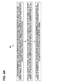
- FIG. 4A is an example flow diagram of operational steps of the host device identifying an audio headset using USB Type-C connector pinning, in accordance with an embodiment of the invention.
- FIG. 4B is an example flow diagram of operational steps of the device, such as an audio headset, using USB Type-C connector pinning, in accordance with at least one embodiment of the present invention.
- a USB system may include a host, a plurality of downstream USB ports, and a plurality of peripheral devices connected in a tiered-star topology. Additional USB hubs may be included in the tiers, allowing branching into a tree structure with up to five tier levels.
- a USB host may have multiple host controllers and each host controller may provide one or more USB ports. Up to 127 devices, including hub devices, may be connected to a single host controller.
- FIG. 1A illustrates an example functional block diagram of a host device 102 and a connected device 104 , such as a headset, to be connected by a cable 130 , such as for example a USB cable.
- the connector 140 such as a USB Type-C connector, has an example USB Type-C connector pinning shown in FIG. 1B .
- the host device 102 has a receptacle 120 , such as for example a USB type-C receptacle to receive the connector 140 plugged into the receptacle 120 .
- the host device 102 may include processing logic 222 that may include one of several central processor units (CPUs) 224 and 225 , a random-access memory (RAM) 226 , and a read-only memory (ROM) 227 .
- processing logic 222 may include programmed logic arrays of sequential and combinatorial logic circuits and state machine logic implementing some or all of the steps performed by embodiments of the invention.
- the source protocol 112 may be embodied as a programmed sequence of executable instructions stored in the RAM or ROM and executed by the central processor unit (CPU) to carry out the functions of embodiments of the invention.
- a new USB Type-C connector 140 is an interface supporting the USB 3.0 level of communication.
- the connector 140 is symmetrical so that it may be plugged in both ways, up-side-up or up-side-down.
- FIG. 1B shows an example of the pinning of the connector 140 .
- the connector will also be similar for both hosts and devices.
- the polarity of the plug and host/device role will be configured by a system called Configuration Channel (CC), which will have two pins CC 1 and CC 2 at each receptacle, but only one of them, CC 1 , is wired trough the cable from the plugs. Using this feature the host and device sides may figure out which way the plug is inserted in the receptacles.
- CC Configuration Channel
- a new Type-C interface may be used for simple audio headsets that would have the Type-C plug. Connection of this kind of headset to a host or a dual role device must be distinguished from any other cable or plug connection.
- Both CC-pins are pulled up in the host side and pulled down in the device side by resistors.
- both may monitor both of the CC-pins and see that at both ends only one pin will change its voltage level. Noting which pin this is, the host or device may figure out which way the plug is inserted locally. After the valid connection is detected, a +5 V VCON voltage is applied to the unused CC-pin for possible active cables.
- the CC-pin principle is shown in FIG. 2 .
- Some devices may not have a receptacle for receiving a cable plug, but they may be instead equipped with a captive cable that is permanently attached to the device.
- the device may be a docking station without a cable. In both cases the host and the device are connected together without a separate cable so there are only two possible ways to connect the device to the host.
- An example of a device with captive cable is an audio headset, which is plugged to phone's USB Type C receptacle.
- One way of distinguishing the audio headset from normal USB Type C devices would be to connect one CC-pin (CC 1 ) permanently to ground. This would result in a 0V voltage level at the host CC-pin and this could be seen as different from a valid connection to a normal USB Type C device, where the voltage level at Host's CC pin would be higher (due to presence of Rd1).
- the active cable supply voltage makes things more complicated, since the active cable supply voltage is connected to CC 2 pin of the cable plug.
- the CC 1 pin is pulled down normally to a detectable voltage and the CC 2 pin may be pulled almost to ground depending on the load in the VCON. Still the host may see that a valid connection happens and may ignore the down pulled CC-pin for a while and connect the +5V VCON supply to that pin.
- the headset it is possible to distinguish the headset from an active cable and still retain the polarity information via the CC-pins.
- the method is to connect only one CC-pin (CC 2 ) permanently to ground in the headset.
- the other CC-pin is connected to ground via a normal value pull down resistor.
- the resistor may, however, be short circuited with a switch (transistor), which is controlled by the VBUS-voltage from the host.
- this kind of headset When this kind of headset is connected to a host, it sees that a valid connection is done and turns on the VBUS voltage and also VCON to the unused CC-pin.
- the unused CC-pin is grounded in the headset, so this will not lead to anywhere, but the VBUS voltage will in the headset turn the short circuit switch on and pull also this CC-pin down.
- This may be detected by the host and it may thus recognize that an audio headset, or in general a device of a predetermined type, is connected.
- the host may also detect the plug polarity from the CC-pin. So, in short also in the invention both CC-pins will be grounded in the headset so that it may be distinguished from an active cable, but not immediately so that the polarity may be first detected.
- FIG. 3 illustrates an example embodiment for identifying an audio headset 104 using USB Type-C connector pinning, in accordance with an embodiment of the invention.
- CC 2 pin is grounded directly and CC 1 pin via the pull down resistor Rd.
- Transistor T is not conducting as there is no voltage at the VBUS.
- the CC 1 will also go to GND on the host side and the host can deduce that an audio headset is connected as both CC-lines are pulled down to hard GND. Alternatively, the host may deduce that an audio headset is connected by detecting that CC 1 or CC 2 is first connected to GND through a resistance and after turning VBUS on the same CC pin is connected to GND without the resistance.
- FIG. 4A is an example flow diagram 400 of operational steps of the host device 102 identifying an audio headset 104 using USB Type-C connector pinning, in accordance with at least one embodiment of the present invention.
- the steps of the flow diagram represent computer code instructions stored in the RAM and/or ROM memory, which when executed by the central processing units (CPU) CPU 224 and/or CPU 225 , carry out the functions of the example embodiments of the invention.
- the steps may be carried out in another order than shown and individual steps may be combined or separated into component steps.
- the flow diagram has the following steps:
- Step 402 determining by a host, an orientation of a device or cable connector of a device, to a host connector of the host, based on whether a first configuration channel terminal or a second configuration channel terminal of the host connector is connected to a terminal of the device or cable connector that is connected through a resistance to a reference potential;
- Step 404 causing by the host, a source voltage to be output on a source voltage output terminal of the host connector to a voltage input terminal of the device or cable connector, after the determination that a terminal of the device or cable connector is connected through a resistance to a reference potential;
- Step 406 determining by the host, whether the device is of a predetermined type, based on whether the terminal of the device or cable connector transitions to the reference potential in response to the source voltage output on the source voltage output terminal.
- FIG. 4B is an example flow diagram 450 of operational steps of the device 104 , such as an audio headset 104 , using USB Type-C connector pinning, in accordance with at least one embodiment of the present invention.
- the steps of the flow diagram represent computer code instructions stored in the RAM and/or ROM memory, which when executed by the central processing units (CPU) CPU 224 ′ and/or CPU 225 ′, carry out the functions of the example embodiments of the invention.
- the steps may be carried out in another order than shown and individual steps may be combined or separated into component steps.
- the flow diagram has the following steps:
- Step 452 enabling, by a device, a host to conduct an initial test to determine whether a connector of the device is plugged into a connector of the host in either an up-side-up or an up-side-down orientation relative to first and second terminals of the host connector, the orientation of the device connector to the host connector being determined by whether a configuration channel input terminal of the device is plugged into the first or the second terminal of the host connector, the configuration channel input terminal being connected through a resistance to a reference potential;
- Step 454 receiving, by the device, a source voltage at a source voltage input terminal
- Step 456 switching, by the device, the configuration channel input terminal, to bypass the resistance and transition the configuration channel input terminal to the reference potential, when the source voltage is received at the source voltage input terminal.
- the embodiments may be implemented as a machine, process, or article of manufacture by using standard programming and/or engineering techniques to produce programming software, firmware, hardware or any combination thereof.
- Some or all of the steps in the flow diagrams disclosed herein may be embodied as hardware program logic included in programmed logic arrays of sequential and/or combinatorial logic circuits and/or state machine logic implementing some or all of the steps performed by embodiments of the invention.
- Any resulting program(s), having computer-readable program code, may be embodied on one or more computer-usable non-transitory media such as resident memory devices, smart cards or other removable memory devices, or transmitting devices, thereby making a computer program product or article of manufacture according to the embodiments.
- computer-usable non-transitory media such as resident memory devices, smart cards or other removable memory devices, or transmitting devices, thereby making a computer program product or article of manufacture according to the embodiments.
- the terms “article of manufacture” and “computer program product” as used herein are intended to encompass a computer program that exists permanently or temporarily on any computer-usable, non-transitory medium.
- memory/storage devices include, but are not limited to, disks, optical disks, removable memory devices such as smart cards, SIMs, WIMs, semiconductor memories such as RAM, ROM, PROMS, etc.
- Transmitting mediums include, but are not limited to, transmissions via wireless communication networks, the Internet, intranets, telephone/modem-based network communication, hard-wired/cabled communication network, satellite communication, and other stationary or mobile network systems/communication links.
Priority Applications (7)
| Application Number | Priority Date | Filing Date | Title |
|---|---|---|---|
| US14/208,654 US9606953B2 (en) | 2014-03-13 | 2014-03-13 | Method, apparatus, and computer program product for entering accessory docking mode in USB type C |
| MX2016011839A MX362143B (es) | 2014-03-13 | 2015-02-25 | Metodo, aparato y producto de programa informatico para introducir modo de acoplamiento de accesorios en usb tipo-c. |
| JP2016555959A JP6244042B2 (ja) | 2014-03-13 | 2015-02-25 | USB Type−Cの付属装置ドッキングモードに移行する方法、装置及びコンピュータプログラム製品 |
| PCT/FI2015/050110 WO2015136148A1 (en) | 2014-03-13 | 2015-02-25 | Method, apparatus, and computer program product for entering accessory docking mode in usb type c |
| EP15711806.8A EP3117329B1 (en) | 2014-03-13 | 2015-02-25 | Method, apparatus, and computer program product for entering accessory docking mode in usb type c |
| CN201580013517.7A CN106104506B (zh) | 2014-03-13 | 2015-02-25 | 用于在usb c型接口中进入附件对接模式的方法、装置和计算机程序产品 |
| PH12016501766A PH12016501766A1 (en) | 2014-03-13 | 2016-09-08 | Method, apparatus, and computer program product for entering accessory docking mode in usb type c |
Applications Claiming Priority (1)
| Application Number | Priority Date | Filing Date | Title |
|---|---|---|---|
| US14/208,654 US9606953B2 (en) | 2014-03-13 | 2014-03-13 | Method, apparatus, and computer program product for entering accessory docking mode in USB type C |
Publications (2)
| Publication Number | Publication Date |
|---|---|
| US20150261714A1 US20150261714A1 (en) | 2015-09-17 |
| US9606953B2 true US9606953B2 (en) | 2017-03-28 |
Family
ID=52727161
Family Applications (1)
| Application Number | Title | Priority Date | Filing Date |
|---|---|---|---|
| US14/208,654 Active 2035-07-09 US9606953B2 (en) | 2014-03-13 | 2014-03-13 | Method, apparatus, and computer program product for entering accessory docking mode in USB type C |
Country Status (7)
| Country | Link |
|---|---|
| US (1) | US9606953B2 (ja) |
| EP (1) | EP3117329B1 (ja) |
| JP (1) | JP6244042B2 (ja) |
| CN (1) | CN106104506B (ja) |
| MX (1) | MX362143B (ja) |
| PH (1) | PH12016501766A1 (ja) |
| WO (1) | WO2015136148A1 (ja) |
Cited By (6)
| Publication number | Priority date | Publication date | Assignee | Title |
|---|---|---|---|---|
| US20170093104A1 (en) * | 2015-09-30 | 2017-03-30 | Apple Inc. | Magnetic adapter |
| US10009029B1 (en) * | 2017-03-22 | 2018-06-26 | Hong Fu Jin Precision Industry (Wuhan) Co., Ltd. | Interface control circuit to match voltage levels between USB devices upon connection |
| US20190025343A1 (en) * | 2017-07-18 | 2019-01-24 | Pegatron Corporation | Test cable and test method using the same |
| US20190236041A1 (en) * | 2018-02-01 | 2019-08-01 | Motorola Solutions, Inc. | Multimode audio accessory connector |
| US10438559B2 (en) | 2016-07-12 | 2019-10-08 | Samsung Electronics Co., Ltd. | Electronic device supporting USB interface and control method for USB interface |
| US11316308B2 (en) * | 2017-12-05 | 2022-04-26 | Jrd Communicaton (Shenzhen) Ltd. | Adapter, multi-device detection system and detection method thereof |
Families Citing this family (33)
| Publication number | Priority date | Publication date | Assignee | Title |
|---|---|---|---|---|
| WO2015199429A1 (en) * | 2014-06-24 | 2015-12-30 | Samsung Electronics Co., Ltd. | Plug connector, electronic apparatus including receptacle and connecting method of electronic apparatus |
| GB2533559A (en) * | 2014-12-16 | 2016-06-29 | Displaylink Uk Ltd | A device capable of being operated in different modes |
| TWI545442B (zh) * | 2015-07-14 | 2016-08-11 | 聯陽半導體股份有限公司 | 通用序列匯流排的偵測電路 |
| US10014637B2 (en) * | 2015-10-20 | 2018-07-03 | Sony Mobile Communications Inc. | Connector receptacle interfacing circuit and method of operation |
| WO2017070941A1 (zh) * | 2015-10-30 | 2017-05-04 | 华为技术有限公司 | USB Type-C插头及线缆 |
| US10503683B2 (en) * | 2015-11-20 | 2019-12-10 | Parade Technologies, Ltd. | Service redirect over USB Type-C |
| US9990328B2 (en) | 2015-12-04 | 2018-06-05 | Qualcomm Incorporated | Increased data flow in universal serial bus (USB) cables |
| CN105677405B (zh) * | 2015-12-31 | 2019-12-24 | 联想(北京)有限公司 | 一种正反插接口处理方法及电子设备 |
| CN105811503B (zh) * | 2016-03-23 | 2018-08-31 | 苏州盛森集成电路科技有限公司 | 一种基于USB Type-C标准的控制通信方法 |
| US20170277650A1 (en) * | 2016-03-25 | 2017-09-28 | Le Holdings (Beijing) Co., Ltd. | User equipment and method for data transmission |
| US10339093B2 (en) * | 2016-03-29 | 2019-07-02 | Intel Corporation | USB interface using repeaters with guest protocol support |
| US20190110119A1 (en) * | 2016-03-29 | 2019-04-11 | Sony Corporation | Receiver and rf signal supply apparatus |
| KR102639882B1 (ko) | 2016-05-04 | 2024-02-26 | 삼성전자주식회사 | 전자 장치 및 그 제어 방법 |
| US10067554B2 (en) * | 2016-05-26 | 2018-09-04 | Silicon Laboratories Inc. | VCONN pull-down circuits and related methods for USB type-C connections |
| US10078616B2 (en) * | 2016-05-26 | 2018-09-18 | Silicon Laboratories Inc. | System, USB Type-C connector and method to transmit encoded data |
| JP6681292B2 (ja) * | 2016-07-20 | 2020-04-15 | キヤノン株式会社 | 電子機器および電子機器の制御方法 |
| CN106469129A (zh) * | 2016-08-31 | 2017-03-01 | 乐视控股(北京)有限公司 | 一种设备连接方法和装置 |
| JP6752675B2 (ja) * | 2016-10-12 | 2020-09-09 | ルネサスエレクトロニクス株式会社 | 半導体装置、半導体装置の制御方法および半導体システム |
| TW201814544A (zh) * | 2016-10-13 | 2018-04-16 | 智微科技股份有限公司 | 可應用於具有通用序列匯流排c型插座的電子裝置之治具與測試系統以及藉助於治具對電子裝置進行測試之方法 |
| US9807507B1 (en) * | 2016-10-17 | 2017-10-31 | Htc Corporation | Electronic accessory apparatus and audible signal transmission method thereof |
| KR102576430B1 (ko) | 2016-11-18 | 2023-09-08 | 삼성전자주식회사 | 인터페이스 장치 |
| US10152448B2 (en) * | 2016-11-29 | 2018-12-11 | Nxp B.V. | Resistor module of a USB interface device and a method of operating a resistor module of a USB interface device |
| DE102016224138A1 (de) | 2016-12-05 | 2018-06-07 | Zf Friedrichshafen Ag | Elektromotor für eine Antriebseinheit eines Antriebsstrangprüfstands |
| US10579107B2 (en) | 2017-03-22 | 2020-03-03 | Microsoft Technology Licensing, Llc | Reversible connector orientation detection circuitry |
| KR102356703B1 (ko) * | 2017-07-07 | 2022-01-28 | 삼성전자주식회사 | 수분 인식 시스템, 이를 포함하는 전자 장치 및 그 수분 인식 방법 |
| US11036670B2 (en) | 2017-10-31 | 2021-06-15 | Huawei Technolgies Co., Ltd. | Electronic device having USB Type-C interface, control method, and readable storage |
| JP7072382B2 (ja) * | 2017-12-28 | 2022-05-20 | キヤノン株式会社 | 電子機器、制御方法およびプログラム |
| US10181686B1 (en) * | 2018-01-22 | 2019-01-15 | Xentris Wireless, Llc | Illuminated USB type C power adapter |
| KR102536143B1 (ko) | 2018-02-09 | 2023-05-24 | 삼성전자주식회사 | 안테나 연결이 가능한 커넥터 및 이를 구비한 전자 장치 |
| US11238005B2 (en) | 2018-07-20 | 2022-02-01 | Samsung Electronics Co., Ltd. | SFF-TA-100X based multi-mode protocols solid state devices |
| US11099623B2 (en) * | 2019-06-29 | 2021-08-24 | Intel Corporation | Power saving for type-C connectors |
| JP2021092861A (ja) * | 2019-12-06 | 2021-06-17 | 東芝テック株式会社 | 電子機器 |
| CN116134431A (zh) * | 2021-01-29 | 2023-05-16 | 华为技术有限公司 | 一种具有正反插接口的装置及检测方法 |
Citations (19)
| Publication number | Priority date | Publication date | Assignee | Title |
|---|---|---|---|---|
| US5884086A (en) | 1997-04-15 | 1999-03-16 | International Business Machines Corporation | System and method for voltage switching to supply various voltages and power levels to a peripheral device |
| US5919253A (en) | 1997-06-25 | 1999-07-06 | Adaptec, Inc. | Hot-switchable SCSI controller having output drivers with quick turn-on |
| US20010013075A1 (en) | 2000-01-27 | 2001-08-09 | Kanji Otsuka | Driver circuit, receiver circuit, and signal transmission bus system |
| US20020169915A1 (en) | 2001-05-08 | 2002-11-14 | Wen-Jen Wu | USB connection-detection circuitry and operation methods of the same |
| US6665801B1 (en) | 2000-01-27 | 2003-12-16 | Symbol Technologies, Inc. | Method and apparatus for charging a self powered USB device at different charge rates according to the charge level of a rechargeable element on the device |
| US20050001179A1 (en) | 2003-06-30 | 2005-01-06 | Scott Gisler | Self powered serial-to-serial or USB-to-serial cable with loopback and isolation |
| US20070167069A1 (en) | 2006-01-13 | 2007-07-19 | Canon Kabushiki Kaisha | Electronic apparatus, control method therefor, program, and computer-readable recording medium |
| US20070241769A1 (en) | 2006-01-16 | 2007-10-18 | Yoon-Beom Song | Usb device and data processing system having the same |
| US7340627B1 (en) | 2002-08-27 | 2008-03-04 | Cypress Semiconductor Corporation | Method and system for supplementing current during enumeration of a USB device |
| US20080126594A1 (en) | 2006-08-17 | 2008-05-29 | Monks Morgan H | System and Method for Enumerating a USB Device Using Low Power |
| US20080178011A1 (en) | 2007-01-18 | 2008-07-24 | Nokia Corporation | Method and apparatus for usb/otg connection providing active hnp requests and saving host power |
| US20080215765A1 (en) | 2007-03-02 | 2008-09-04 | Microchip Technology Incorporated | Detecting Connection to a USB Host or Hub Without Using an Extra Status Input |
| US20080314979A1 (en) | 2007-06-22 | 2008-12-25 | Sun Microsystems, Inc. | Cable management systems |
| US20090209131A1 (en) | 2007-01-05 | 2009-08-20 | Apple Inc. | Backward compatible connector system |
| US20100299449A1 (en) | 2009-05-20 | 2010-11-25 | Apple Inc. | Systems and methods for adjusting signaling properties based on cable attributes |
| US20100313226A1 (en) | 2009-06-08 | 2010-12-09 | Chris Cholas | Media bridge apparatus and methods |
| US20110208980A1 (en) | 2010-02-22 | 2011-08-25 | Benjamin Brooks | Methods and apparatus for intelligently providing power to a device |
| US20110316838A1 (en) * | 2010-06-29 | 2011-12-29 | Jung-Keun Ahn | Apparatus for supplying power, display device having the same, and driving method thereof |
| US20120078690A1 (en) | 2010-09-24 | 2012-03-29 | Harriman David J | Power allocation controller |
Family Cites Families (7)
| Publication number | Priority date | Publication date | Assignee | Title |
|---|---|---|---|---|
| JP4840060B2 (ja) * | 2006-10-03 | 2011-12-21 | ソニー株式会社 | ヘッドホン、ノイズ低減処理システム及びノイズ低減処理方法 |
| US8928189B2 (en) * | 2007-11-15 | 2015-01-06 | Nokia Corporation | Power connector between serial interfaces |
| US8601173B2 (en) * | 2010-06-30 | 2013-12-03 | Silicon Image, Inc. | Detection of cable connections for electronic devices |
| JP5382045B2 (ja) * | 2011-03-31 | 2014-01-08 | 株式会社ニコン | 電子機器、電子機器システムおよびプログラム |
| US9047073B2 (en) * | 2011-02-14 | 2015-06-02 | Nikon Corporation | System method for detecting a type of device wherein a potential level of the device determines if power should be supplied based on the type of the device |
| US8478913B2 (en) * | 2011-11-30 | 2013-07-02 | Apple Inc. | Adapter for electronic devices |
| US8762605B2 (en) * | 2011-11-30 | 2014-06-24 | Apple Inc. | Adapter for electronic devices |
-
2014
- 2014-03-13 US US14/208,654 patent/US9606953B2/en active Active
-
2015
- 2015-02-25 JP JP2016555959A patent/JP6244042B2/ja active Active
- 2015-02-25 CN CN201580013517.7A patent/CN106104506B/zh active Active
- 2015-02-25 MX MX2016011839A patent/MX362143B/es active IP Right Grant
- 2015-02-25 EP EP15711806.8A patent/EP3117329B1/en active Active
- 2015-02-25 WO PCT/FI2015/050110 patent/WO2015136148A1/en active Application Filing
-
2016
- 2016-09-08 PH PH12016501766A patent/PH12016501766A1/en unknown
Patent Citations (19)
| Publication number | Priority date | Publication date | Assignee | Title |
|---|---|---|---|---|
| US5884086A (en) | 1997-04-15 | 1999-03-16 | International Business Machines Corporation | System and method for voltage switching to supply various voltages and power levels to a peripheral device |
| US5919253A (en) | 1997-06-25 | 1999-07-06 | Adaptec, Inc. | Hot-switchable SCSI controller having output drivers with quick turn-on |
| US20010013075A1 (en) | 2000-01-27 | 2001-08-09 | Kanji Otsuka | Driver circuit, receiver circuit, and signal transmission bus system |
| US6665801B1 (en) | 2000-01-27 | 2003-12-16 | Symbol Technologies, Inc. | Method and apparatus for charging a self powered USB device at different charge rates according to the charge level of a rechargeable element on the device |
| US20020169915A1 (en) | 2001-05-08 | 2002-11-14 | Wen-Jen Wu | USB connection-detection circuitry and operation methods of the same |
| US7340627B1 (en) | 2002-08-27 | 2008-03-04 | Cypress Semiconductor Corporation | Method and system for supplementing current during enumeration of a USB device |
| US20050001179A1 (en) | 2003-06-30 | 2005-01-06 | Scott Gisler | Self powered serial-to-serial or USB-to-serial cable with loopback and isolation |
| US20070167069A1 (en) | 2006-01-13 | 2007-07-19 | Canon Kabushiki Kaisha | Electronic apparatus, control method therefor, program, and computer-readable recording medium |
| US20070241769A1 (en) | 2006-01-16 | 2007-10-18 | Yoon-Beom Song | Usb device and data processing system having the same |
| US20080126594A1 (en) | 2006-08-17 | 2008-05-29 | Monks Morgan H | System and Method for Enumerating a USB Device Using Low Power |
| US20090209131A1 (en) | 2007-01-05 | 2009-08-20 | Apple Inc. | Backward compatible connector system |
| US20080178011A1 (en) | 2007-01-18 | 2008-07-24 | Nokia Corporation | Method and apparatus for usb/otg connection providing active hnp requests and saving host power |
| US20080215765A1 (en) | 2007-03-02 | 2008-09-04 | Microchip Technology Incorporated | Detecting Connection to a USB Host or Hub Without Using an Extra Status Input |
| US20080314979A1 (en) | 2007-06-22 | 2008-12-25 | Sun Microsystems, Inc. | Cable management systems |
| US20100299449A1 (en) | 2009-05-20 | 2010-11-25 | Apple Inc. | Systems and methods for adjusting signaling properties based on cable attributes |
| US20100313226A1 (en) | 2009-06-08 | 2010-12-09 | Chris Cholas | Media bridge apparatus and methods |
| US20110208980A1 (en) | 2010-02-22 | 2011-08-25 | Benjamin Brooks | Methods and apparatus for intelligently providing power to a device |
| US20110316838A1 (en) * | 2010-06-29 | 2011-12-29 | Jung-Keun Ahn | Apparatus for supplying power, display device having the same, and driving method thereof |
| US20120078690A1 (en) | 2010-09-24 | 2012-03-29 | Harriman David J | Power allocation controller |
Non-Patent Citations (3)
| Title |
|---|
| International Search Report and Written Opinion for Application No. PCT/F12015/050110 issued on May 27, 2015. |
| USB Type C specification, USB.org, http://www.usb.org/developers/usbtypec/; version 1.0. * |
| USB Type-C Cable and Connector Specification Revision 1.0, Aug. 11, 2014. |
Cited By (11)
| Publication number | Priority date | Publication date | Assignee | Title |
|---|---|---|---|---|
| US20170093104A1 (en) * | 2015-09-30 | 2017-03-30 | Apple Inc. | Magnetic adapter |
| US9991657B2 (en) * | 2015-09-30 | 2018-06-05 | Apple Inc. | Magnetic adapter |
| US10547151B2 (en) | 2015-09-30 | 2020-01-28 | Apple Inc. | Magnetic adapter |
| US10438559B2 (en) | 2016-07-12 | 2019-10-08 | Samsung Electronics Co., Ltd. | Electronic device supporting USB interface and control method for USB interface |
| US10009029B1 (en) * | 2017-03-22 | 2018-06-26 | Hong Fu Jin Precision Industry (Wuhan) Co., Ltd. | Interface control circuit to match voltage levels between USB devices upon connection |
| US20190025343A1 (en) * | 2017-07-18 | 2019-01-24 | Pegatron Corporation | Test cable and test method using the same |
| US10775415B2 (en) * | 2017-07-18 | 2020-09-15 | Pegatron Corporation | Test cable used in USB 3.0 type C and test method using the same |
| US11316308B2 (en) * | 2017-12-05 | 2022-04-26 | Jrd Communicaton (Shenzhen) Ltd. | Adapter, multi-device detection system and detection method thereof |
| US20190236041A1 (en) * | 2018-02-01 | 2019-08-01 | Motorola Solutions, Inc. | Multimode audio accessory connector |
| US10452584B2 (en) * | 2018-02-01 | 2019-10-22 | Motorola Solutions, Inc. | Multimode audio accessory connector |
| US10698850B2 (en) | 2018-02-01 | 2020-06-30 | Motorola Solutions, Inc. | Multimode audio accessory connector |
Also Published As
| Publication number | Publication date |
|---|---|
| JP2017511937A (ja) | 2017-04-27 |
| JP6244042B2 (ja) | 2017-12-06 |
| US20150261714A1 (en) | 2015-09-17 |
| EP3117329B1 (en) | 2018-10-31 |
| CN106104506A (zh) | 2016-11-09 |
| EP3117329A1 (en) | 2017-01-18 |
| WO2015136148A1 (en) | 2015-09-17 |
| PH12016501766B1 (en) | 2016-12-19 |
| MX2016011839A (es) | 2016-12-02 |
| MX362143B (es) | 2018-12-24 |
| CN106104506B (zh) | 2019-01-04 |
| PH12016501766A1 (en) | 2016-12-19 |
Similar Documents
| Publication | Publication Date | Title |
|---|---|---|
| US9606953B2 (en) | Method, apparatus, and computer program product for entering accessory docking mode in USB type C | |
| US10409311B2 (en) | Pull-down circuitry for an apparatus | |
| US11749954B2 (en) | Semiconductor USB device for detecting foreign substances and method of operating the same | |
| KR101699839B1 (ko) | 전자 디바이스들을 위한 케이블 연결들의 검출 | |
| CN106291210B (zh) | Usb接口检测器、检测方法、usb连接器及电子设备 | |
| CN109313626B (zh) | 通用串行总线(usb)电缆类型检测和控制技术 | |
| US10503683B2 (en) | Service redirect over USB Type-C | |
| CN100495377C (zh) | 检测插入外设类型的方法和终端接口 | |
| USRE45050E1 (en) | Systems and methods for determining the configuration of electronic connections | |
| US9547573B2 (en) | Serial communication over communication control pin | |
| US20190011386A1 (en) | Water recognition system, electronic device including the same, and method of recognizing water thereby | |
| KR20160030261A (ko) | 전류 제한을 변경하는 장치 및 방법 | |
| CN104714912A (zh) | 一种多卡检测装置、多卡检测系统及其方法 | |
| JP2019015730A (ja) | 水分認識機能を含む電子装置及びその水分認識方法並びに水分認識システム | |
| US9502911B2 (en) | Battery charging device with charging profile data update facility | |
| US9864714B2 (en) | Electronic system for performing recharging and data communication | |
| US20140201420A1 (en) | Transmission interface system with detection function and method | |
| US20140245037A1 (en) | System and Method for Utilizing Standard Four Wire USB for Multiple Power Modes and Out of Band State Management | |
| CN108513656B (zh) | 控制方法、usb系统和电子装置 | |
| US10615550B2 (en) | Earphone recognition and connection methods and circuits and storage medium |
Legal Events
| Date | Code | Title | Description |
|---|---|---|---|
| AS | Assignment |
Owner name: NOKIA CORPORATION, FINLAND Free format text: ASSIGNMENT OF ASSIGNORS INTEREST;ASSIGNOR:TALMOLA, PEKKA HEIKKI KALERVO;REEL/FRAME:032580/0683 Effective date: 20140324 |
|
| AS | Assignment |
Owner name: NOKIA TECHNOLOGIES OY, FINLAND Free format text: ASSIGNMENT OF ASSIGNORS INTEREST;ASSIGNOR:NOKIA CORPORATION;REEL/FRAME:034781/0200 Effective date: 20150116 |
|
| STCF | Information on status: patent grant |
Free format text: PATENTED CASE |
|
| MAFP | Maintenance fee payment |
Free format text: PAYMENT OF MAINTENANCE FEE, 4TH YEAR, LARGE ENTITY (ORIGINAL EVENT CODE: M1551); ENTITY STATUS OF PATENT OWNER: LARGE ENTITY Year of fee payment: 4 |