US9598352B2 - Process and device for the production of polyhedral boranes - Google Patents
Process and device for the production of polyhedral boranes Download PDFInfo
- Publication number
- US9598352B2 US9598352B2 US14/357,684 US201214357684A US9598352B2 US 9598352 B2 US9598352 B2 US 9598352B2 US 201214357684 A US201214357684 A US 201214357684A US 9598352 B2 US9598352 B2 US 9598352B2
- Authority
- US
- United States
- Prior art keywords
- reaction
- polyhedral
- quaternary amine
- amine salt
- tetraborohydride
- Prior art date
- Legal status (The legal status is an assumption and is not a legal conclusion. Google has not performed a legal analysis and makes no representation as to the accuracy of the status listed.)
- Expired - Fee Related
Links
- PQNGCJMTGBBMHJ-UHFFFAOYSA-N C.CC.[HH] Chemical compound C.CC.[HH] PQNGCJMTGBBMHJ-UHFFFAOYSA-N 0.000 description 1
- YLJCCWCOVFYQOB-UHFFFAOYSA-N C.C[N+](C)(C)C.[CH3-] Chemical compound C.C[N+](C)(C)C.[CH3-] YLJCCWCOVFYQOB-UHFFFAOYSA-N 0.000 description 1
- UDLABYWFHQTOKO-UHFFFAOYSA-N C[N+](C)(C)C.[CH3-] Chemical compound C[N+](C)(C)C.[CH3-] UDLABYWFHQTOKO-UHFFFAOYSA-N 0.000 description 1
Images


Classifications
-
- C—CHEMISTRY; METALLURGY
- C07—ORGANIC CHEMISTRY
- C07C—ACYCLIC OR CARBOCYCLIC COMPOUNDS
- C07C211/00—Compounds containing amino groups bound to a carbon skeleton
- C07C211/62—Quaternary ammonium compounds
- C07C211/63—Quaternary ammonium compounds having quaternised nitrogen atoms bound to acyclic carbon atoms
-
- C—CHEMISTRY; METALLURGY
- C01—INORGANIC CHEMISTRY
- C01B—NON-METALLIC ELEMENTS; COMPOUNDS THEREOF; METALLOIDS OR COMPOUNDS THEREOF NOT COVERED BY SUBCLASS C01C
- C01B35/00—Boron; Compounds thereof
- C01B35/02—Boron; Borides
- C01B35/026—Higher boron hydrides, i.e. containing at least three boron atoms
Definitions
- the present invention provides methods and devices for producing polyhedral boron compounds.
- the present invention relates to a one-pot, anhydrous pyrolysis of a quaternary amine salt with a tetraborohydride to produce the polyhedral boron compounds using a vented milling reactor device.
- the process is tunable to give high yields of the desired polyhedral borane, and it is suitable for large scale reactions.
- Polyhedral boranes especially decahydrodecaborate [B 10 H 10 ] 2 ⁇ and dodecahydrododecaborate [B 12 H 12 ] 2 ⁇ salts are useful compounds for a variety of purposes including for propellant fuels, battery electrolytes, and as precursors to carborane compounds, which have a variety of applications in various fields including the biomedical field. Decahydrodecaborate, dodecahydrododecaborate, and carboranes are stable in air, water, and high temperatures.
- polyhedral boranes Despite the utility and commercial value of polyhedral boranes, potential applications for polyhedral boranes are impeded by the difficulty of manufacturing polyhedral boranes.
- Existing methods of producing polyhedral boranes present a number of safety concerns. First, some methods rely on the use of toxic and difficult to handle reagents such as diborane, which can explode on contact with air. Second, the pathway to polyhedral boranes proceeds through a large number of intermediates, some of which are highly unstable and can be explosive. Further complicating the reaction, a large amount of flammable gasses, including H 2 gas, are produced during the reaction, so the reactions must be conducted to avoid the build up of pressure, and also to dilute the flammable gas to safe levels.
- Control of the polyhedral boranes produced has been difficult in prior processes. Control to produce a high yield of a single polyhedral borane has also been difficult. Dodecahydrododecaborates have been produced through various methods but these methods have been unable to produce high levels of decahydrodecaborate, the more valuable of the two polyhedral boranes. As decahydrodecaborate and dodecahydrododecaborate are often produced together, separation must be provided for the pure products. Previous methods of separation have been labor intensive.
- One aspect of the invention provides a process for the production of polyhedral boranes.
- the process is generally an anhydrous, one-pot process that comprises a pyrolytic reaction of a tetraborohydride with a quaternary amine salt to form the polyhedral borane.
- polyhedral boranes are produced without isolation of the Lewis base-borane complex.
- the invention also provides a device for the production of polyhedral boranes.
- FIG. 1 is a block diagram illustrating the arrangement of subsystems of a milling reactor system.
- FIG. 2 is a schematic diagram of a milling reactor system.
- FIG. 3 is a schematic diagram illustrating components of a reaction vessel and a power drive system.
- FIG. 4 is a cross-sectional view of the reaction vessel and power drive system illustrated in FIG. 3 .
- FIG. 5 is a second cross-sectional view of the reaction vessel and power drive system illustrated in FIG. 3 .
- FIG. 6 is a third cross-sectional view of the reaction vessel and power drive system illustrated in FIG. 3 .
- FIG. 7 is a cross-sectional view of a continuous flow reaction vessel.
- FIG. 8 is an NMR spectrum showing the B-11 NMR chemical shifts associated with B 10 H 10 .
- This spectrum includes a signal at ⁇ 0.8 ppm and one at ⁇ 29 ppm in a 1:4 ratio. The spectrum shows that the process has minimal side products.
- FIG. 9 is an NMR spectrum showing the B-11 NMR chemical shift associated with B 12 H 12 . This spectrum includes a singlet at ⁇ 15 ppm. This spectrum confirms that the process results in the production of B 12 H 12 with minimal side products.
- the present invention relates to an improved process for the production of polyhedral boranes.
- the process is generally an anhydrous, one-pot process that comprises a pyrolytic reaction of a tetraborohydride with a quaternary amine salt to form the polyhedral borane.
- polyhedral boranes are produced without isolation of a Lewis base-borane complex.
- a device is provided for the production of polyhedral boranes.
- Lewis base-borane complexes are formed by the reaction of a borohydride reagent with a Lewis base.
- the resulting Lewis base-borane complex has been generally thought to facilitate the formation of polyhedral boranes without a diborane reagent.
- the Lewis base-borane complexes as an intermediate to the process, introduce atom inefficiencies, as the Lewis base is not incorporated in the final product, and generally represents an additional synthetic step, reducing the efficiency for producing polyhedral boranes.
- decahydrodecaborane [B 10 H 10 ] 2 ⁇ and dodecahydrododecaborane [B 12 H 12 ] 2 ⁇ are produced via a one-pot, anhydrous pyrolytic process.
- the process comprises reacting a tetraborohydride with a quaternary amine salt to give the polyhedral boranes as shown in Reaction Scheme 1 below.
- Another aspect of the invention is the production of polyhedral boranes without the isolation of a Lewis base-borane complex.
- a process for producing the polyhedral boranes in a milling reactor provides a controlled environment for the production of polyhedral boranes including control over temperature and pressure and also provides a grinding/mixing mechanism to improve the yield of the polyhedral boranes.
- One aspect of the invention described herein is the scalability of the reaction.
- the parameters provided allow the reaction to be safely scaled to produce higher quantities of reaction.
- the reaction may be accomplished in gram quantities, kilogram quantities, or ton quantities.
- the pyrolytic reaction between the quaternary amine salt and the tetraborohydride is conducted in a single pot. That is, the formation of the polyhedral boranes is conducted in a single vessel without the need for isolation of intermediates or for transferring the reactants to a different vessel.
- This aspect provides advantages in the yield of the reaction, because no product is lost in isolation, it also facilitates the automation of a process which otherwise involves a number of different steps.
- the quench step is performed in the same vessel as the pyrolytic reaction.
- the reaction is anhydrous.
- anhydrous it is meant that the components of the reaction (which include the reactants, any additional solvents, and the gasses that the reaction is conducted under) are substantially free of water.
- a liquid is anhydrous when the total water content of the liquid is less than 0.01%.
- solids are anhydrous when the weight of the solid is less than 0.01% water.
- the water content of the gas is less than 5 ppm.
- Tetraborohydrides are safe to handle and readily available. Tetraborohydrides are compounds comprising the BH 4 ⁇ anion. The compounds are typically stabilized by a cation (M + ). Cations may be chosen from, without limitation, Lithium (Li + ), Potassium (K + ), Sodium (Na + ), and the like.
- the tetraborohydride provided to the reaction vessel may be anhydrous.
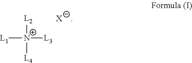
- the tetraborohydride reagent is reacted with a quaternary amine salt of the Formula (I).
- the quaternary amine salt comprises four substituents (L 1-4 ) on the nitrogen atom.
- L 1-4 are independently selected from hydrocarbyl and substituted hydrocarbyl having from 1 to 20 carbon atoms.
- L 1-4 are independently selected from hydrocarbyl groups having from 1 to 6 carbon atoms.
- L 1-4 are independently chosen from methyl, ethyl, propyl, and butyl.
- L 1-4 are ethyl.
- the positively charged quaternary amine is stabilized by an anion to form the salt.
- the anion (X ⁇ ) may be any acceptable anion.
- the stabilizing ion is chosen from F ⁇ , Cl ⁇ , Br ⁇ , I ⁇ , and OH ⁇ .
- the stabilizing ion is Cl ⁇
- the quaternary amine salt is tetraethyl ammonium chloride.
- the quaternary amine salt is provided to the reaction vessel in an anhydrous state.
- the anhydrous quaternary amine salt may be dried by any known technique for drying the quaternary amine salt.
- the quaternary amine salt is dried by placing the quaternary amine salt in a negative pressure environment, which facilitates evaporation and removal of water. Once dried, the quaternary ammonium salt is kept free from water and ambient air; preferably, it is kept under an inert atmosphere such as Argon or Nitrogen.
- the quaternary amine salt may be dried in the reactor by operating the reactor containing the quaternary amine salt under vacuum at a temperature of about 125° C. and then cooling the dried quaternary amine salt.
- the mole-to-mole ratio of the tetraborohydride and the quaternary amine salt can and will vary within the ranges defined herein.
- the ratio of tetraborohydride to the quaternary amine salt may vary between about 1:0.1 to about 1:5.
- the mole-to-mole ratio of the tetraborohydride to the quaternary amine salt may vary between about 1:0.8 to about 1.2, more preferably in a ratio of about 1:1 to about 1:2.
- the ratio of the tetraborohydride to the quaternary amine salt may range between about 1:0.8 to about 1:1, between about 1:0.9 to about 1:1.1, between about 1:0.9 to about 1:1.2, between about 1.1 to about 1.2, between about 1:1.3 to about 1:1.3, between about 1:1.3 to about 1:1.5, and between about 1:1.4 to about 1:1.5.
- the ratio of the tetraborohydride to the quaternary amine salt is about 1:1.
- an optional catalyst is added to the reaction between the quaternary amine salt and the tetraborohydride.
- the optional catalyst is preferably a Lewis acid such as boron trifluoride, trimethoxyboron, or aluminum chloride.
- the optional catalyst may be added to the reaction in a ratio of about 0.1 to about 5 mol % of the tetraborohydride reagent.
- the amount of optional catalyst is about 0.1 to about 0.7 mol % of the tetraborohydride reagent.
- the amount of Lewis acid catalyst is about 0.5 mol % of the tetraborohydride reagent.
- the reaction may further comprise an optional anhydrous solvent.
- Anhydrous solvents may be obtained commercially or may be dried through various drying mechanisms such as reaction with sodium, use of a drying agent, water scavengers, or another technique known in the art. Solvents include both polar solvents and non-polar solvents.
- Non-limiting examples of specific polar organic solvents include acetonitrile, acetic acid, acetone, allyl alcohol, butyl acetate, n-butanol, chlorobenzene, chloromethane, cyclopentane, dichloromethane (DCM), dichloroethane, dimethyl sulfonic acid (DMSO), ethanol, ethyl acetate, ethylene dichloride, ethylene bromide, fluorobenzene, formic acid, isobutylmethylketone, isopropanol, isopropyl acetate, methanol, methylene bromide, methylene chloride, methyl iodide, methylethylketone, methyltetrahydrofuran, pentyl acetate, n-propanol, n-propyl acetate, tetrahydrofuran, tetrachloroethane, trichloroethane, water
- Non-limiting examples of specific non-polar organic solvents include benzene, chloroform cyclohexane, cyclopentane, diethyl ether, dioxane, heptane, hexane, pentane, toluene, xylene and the like.
- a high boiling solvent is preferred.
- high boiling solvents are bis(2-methoxyethyl)ether, 1,2-dimethoxyethane, N,N-dimethylformamide, dimethylsulfoxide, decane, dodecane, hexalin, decalin, tetralin, mixed dimethyl succinate, triesters of 1,2,4-benzenetricarboxylic acid, mineral oils and mixtures thereof.
- the solvent can be provided in a range of acceptable amounts.
- the amount of solvent used depends on the amount of tetraborohydride reagent and the size of the reactor.
- the solvent will be provided in a v/v with the substrates of about 10% to about 200%.
- the solvent is provided in a v/v of about 50% to about 100%.
- the solvent is provided in a v/v of about 20% to about 50%.
- the reaction temperature may vary over the course of the reaction. Depending on the size of the reaction, heating to the reaction temperature may occur over a period of time, generally from 0.5 hours to about 3 hours. In a preferred embodiment, the reaction temperature will be reached after about 90 minutes.
- the reaction temperature for the pyrolysis of a tetraborohydride and a quaternary amine salt may range between about 150° C. and about 300° C. In one embodiment, the reaction is carried out at a temperature ranging between about 160° C. and about 200° C. In another embodiment, the temperature ranges between about 170° C. and about 190° C., between about 185° C. and about 205° C., between about 200° C. and about 220° C., between about 215° C.
- the temperature may be kept at any temperature between or including the above-listed values.
- the reaction is conducted between about 180° C. and about 190° C.
- the pressure of the reaction is regulated, for example, by the reactor described in Part II. Over the pyrolytic process, hydrogen gas is produced which increases the pressure of the vessel. The gas generally is released to maintain the pressure, for example, as described in Part II.
- the pressure during the reaction may vary throughout the reaction between about 0.2 atm and between about 8 atm. In one embodiment, the pressure is regulated between about 0.4 atm and about 3.0 atm. In a preferred embodiment, the pressure is regulated between about 0.5 atm and about 2 atm.
- the pyrolytic reaction between the quaternary amine salt and the tetraborohydride is conducted under anhydrous conditions.
- Anhydrous conditions are maintained through drying of the reagents before introduction into the reaction vessel, and maintenance of an inert atmosphere within the reaction vessel.
- the reaction vessel is preferably opened to vent, and the vents are preferably configured such that ambient air cannot enter the reaction vessel.
- An example of such a configuration is provided in Part II.
- the amount of time that the tetraborohydride and the quaternary amine salt are allowed to react may depend on whether the process is being optimized for [B 10 H 10 ] 2 ⁇ or [B 12 H 12 ] 2 ⁇ and on the temperature of the reaction.
- the reaction temperature is held for a period of time ranging from about 4 hours to about 24 hours.
- the reaction temperature is held for a period of time from about 10 hours to about 20 hours.
- the peak temperature is held from about 3 hours to about 6 hours to optimize the process for [B 10 H 10 ] 2 ⁇ .
- the peak temperature is held from about 8 hours to about 20 hours to optimize the reaction for [B 12 H 12 ] 2 ⁇ .
- the reaction is preferably quenched to destroy any reactive intermediates in the reaction vessel.
- the reaction of the tetraborohydride with the quaternary ammonium salt may be quenched by adding a quench reagent to the reaction vessel.
- the intermediates are highly reactive, thus quenching occurs almost immediately to the introduction of the quench solution. Due to the fact that some of the reactive intermediates may explode on contact with air, it is preferable to introduce the quench reagent to the reaction vessel through an air free mechanism.
- Quench reagents are preferably reagents that react with unwanted borohydride intermediates (such as hydrolytically unstable intermediates) and do not react with the desired polyhedral boranes.
- the quench reagent can be acids or bases as long as they react with the hydrolytically unstable borohydride intermediates.
- the quench reagent is a weak acid or base. Non-limiting examples include acetic acid, alkyl amines, ammonia, formic acid, hydrofluoric acid, hydrocyanic acid, oxalic acid, and pyridine.
- the quench reagent is acetic acid.
- Facilitating contact of the quench reagent with the reactive boranes can be accomplished by providing agitation of the vessels contents with a liquid quench reagent. Agitation should be sufficient to cause contact with the entire vessel and may be provided by rotation of the vessel, stirring, and the like.
- the quench reagent is volatile and added to the reaction vessel above the boiling point of the quench reagent. This causes vaporization of the quench reagent and, facilitates the quench reagent contacting the reactive species in the vessel.
- the method of producing the polyhedral boranes may further comprise a purification step to isolate the desired product.
- the unpurified reaction mixture may comprise [B 10 H 10 ] 2 ⁇ and/or [B 12 H 12 ] 2 ⁇ ′ including salts and complexes thereof, as well as a large amount of salt.
- the salt is comprised of the stabilizing counterions for the quaternary ammonium salt and for the tetraborohydride (MX) as depicted in Reaction Scheme 1. Purification from this salt may be provided by any known method such as through chromatography, or vacuum drying.
- [B 10 H 10 ] 2 ⁇ , [B 12 H 12 ] 2 ⁇ , and the salt (MX) are also separated [B 10 H 10 ] 2 ⁇ , [B 12 H 12 ] 2 ⁇ , and the salt (MX) may be separated by chromatography or through distillation. More preferably, [B 10 H 10 ] 2 ⁇ , [B 12 H 12 ] 2 ⁇ , and the salt (MX) are separated based on their differential solubility in alcohol. Another surprising aspect of the invention is that the [B 10 H 10 ]N(Et 4 ) 2 and [B 12 H 12 ]N(Et 4 ) 2 may be separated based on differential solubility in methanol.
- the mixture is washed with methanol, which selectively solubilizes [B 10 H 10 ]N(Et 4 ) 2 . Evaporation of methanol gives the pure [B 10 H 10 ]N(Et 4 ) 2 .
- the remaining mixture of the salt (MX) and [B 12 H 12 ]N(Et 4 ) 2 is separated based on differential solubility in acetonitrile, or another like solvent.
- Other [B 10 H 10 ] 2 ⁇ and [B 12 H 12 ] 2 ⁇ may be separated from each other through differential solubility in lower alcohols such as methanol, ethanol, propanol, allyl alcohol, and butanol.
- the salt (MX) may be separated using a variety of organic solvents.
- the yield of the polyhedral boranes will vary.
- the yield of [B 10 H 10 ] 2 ⁇ may be at least about 50%.
- the yield of [B 10 H 10 ] 2 ⁇ may range between about 35% and about 45%.
- the yield of [B 10 H 10 ] 2 ⁇ may range between about 40% and about 50%.
- the yield of [B 10 H 10 ] 2 ⁇ may be greater than about 50%.
- the yield of for [B 12 H 12 ] 2 ⁇ may be at least about 50%.
- the yield of for [B 12 H 12 ] 2 ⁇ may range between about 40% and about 50%.
- the yield of for [B 12 H 12 ] 2 ⁇ may be greater than about 50%.
- the pyrolytic process described herein above may be carried out in a milling reactor system.
- the milling reactor system may include a sealed reaction vessel in which the pyrolytic process is carried out at a regulated temperature and pressure under anhydrous conditions as described above.
- the reaction vessel may rotate in order to intimately admix the reactants using a method similar to that used in existing ball-mill devices.
- This admixing process may be further enhanced by the inclusion of particulate grinding media within the reaction vessel along with the tetraborohydride and the quaternary amine salt reagents of the pyrolytic reaction.
- the pyrolytic process may be carried out using all solid-phase reagents, or any combination of solid-phase, liquid phase, and vapor phase reactants.
- the milling reactor system 100 comprises a reaction vessel 102 within which the reagents of the pyrolytic reaction, an inert gas, and an amount of grinding media may be placed to conduct the pyrolytic process.
- the polyhedral borane products may be removed at the conclusion of the pyrolytic process from the reaction vessel 102 .
- the reaction vessel 102 may be rotated by torque supplied by a power drive system 104 in order continuously mix the contents of the reaction chamber during the pyrolytic process.
- the milling reactor system 100 may conduct the pyrolytic process under controlled temperature and pressure conditions.
- the reaction vessel 102 may be heated and/or cooled during the pyrolytic process by a temperature control system 106 in order to maintain the temperature of the contents of the reaction vessel 102 within the range of temperatures defined herein above. Because the reaction vessel 102 is typically operated under sealed conditions, the pressure within the reaction vessel 102 may be maintained by a pressure regulation system 108 to within the pressure range described herein above.
- the pressure regulation system 108 may also remove excess gaseous products including, but not limited to, hydrogen gas and other vapor-phase byproducts of the pyrolytic reaction from within the reaction vessel 102 . These gaseous products may be captured, reclaimed, or released in a non-explosive and non-toxic form by a waste treatment/reclamation system 110 .
- hydrogen gas produced by the pyrolytic process and vented from the reaction vessel 102 may be combined with an excess of an inert gas by the waste treatment/reclamation system 110 , resulting in a non-explosive dilute hydrogen/inert gas mixture that may be released into the surrounding atmosphere.
- FIG. 2 is a schematic diagram illustrating an assembly of components making up the milling reactor system 100 in an aspect.
- the reaction vessel 102 may include a rotating container 202 outfitted with a hatch 204 that may be opened to load in reagents and grinding media for the pyrolytic process and to unload the resulting polyhedral borane products at the completion of the pyrolytic process.
- the hatch 204 Prior to initiating the pyrolytic process, the hatch 204 may be closed and sealed to prevent reactive gases such as air or oxygen from entering the container 202 and to prevent gaseous byproducts such as hydrogen gas from exiting the container 202 , thereby reducing the formation or uncontrolled release of explosive byproducts from the pyrolytic process.
- the hatch may be attached to a flange fitting 207 by any known attachment means capable of reversibly attaching and detaching from the flange fitting 207 , including, but not limited to, screws, bolts, and clamps.
- the hatch 204 may be sealed using a gasket 205 between the hatch 204 and a flange fitting 207 of the rotating container 202 .
- the gasket 205 may be constructed from any material capable of sealing the hatch at the temperature and pressures of the pyrolytic process described herein above, as well as resisting degradation due to the reactive byproducts of the pyrolytic reaction.
- a Teflon gasket may be used to seal the hatch 204 to the flange fitting 207 .
- the container material may be selected to fulfill any one or more criteria, including, but not limited to: maintaining structural integrity at the pyrolytic process temperatures described above, withstanding the pressures generated during the pyrolysis process, and resisting wear on the interior surfaces of the container 202 due to the impact of the grinding media and/or caustic reagents, byproducts and final products of the pyrolytic process.
- Non-limiting examples of materials suitable for the construction of the container 202 include plated or stainless steel, such as 304 stainless steel, glass-lined steel, Teflon-lined steel, brass-lined steel, and brass.
- Grinding media may be introduced into the rotating container 202 prior to the initiation of the pyrolysis process.
- Any known grinding media may be used, including, but not limited to, balls or spherical particles made of an inert material including, but not limited to, alumina and/or chromium.
- the grinding media may be made of a catalytic material rather than an inert material, or the grinding material may be an inert material coated with a catalytic material.
- the grinding media may have a particle diameter of about 3 ⁇ 8 inches.
- the particle size of the grinding media may be uniform, or a mixture of different particle sizes may be used to enhance the grinding action of the grinding media.
- FIG. 6 is a cross-section of the rotating container 202 near the gas outlet 214 , corresponding to the corss-section marked C-C in FIG. 3 .
- a screen 602 may cover the opening within the internal volume of the rotating container 602 in order to prevent the grinding media from exiting the rotating container 202 .
- the rotating container 202 may be any size appropriate for the production of polyhedral borane products at the desired scale.
- the size of the rotating container 202 may be determined by any one or more factors including, but not limited to: the desired rate of production of polyhedral borane products, the size of the power drive system 104 and associated structural elements required to support and rotate the rotating container 202 , and/or the capacity of the waste treatment/reclamation system 110 .
- the thickness of the walls of the rotating container 202 may be specified in order to provide sufficient material thickness to compensate for wear induced by the grinding media and chemical erosion during the working life of the rotating container 202 .
- the range of internal pressures experienced in the interior of the rotating container 202 are typically relatively low during the pyrolysis process as described herein, if higher internal pressures are desired, the thickness of the walls of the rotating container 202 may be increased accordingly.
- the container may include a wear-resistant liner to extend the working life of the container 202 .
- the power drive system 104 produces and applies the torque needed to rotate the reaction vessel 102 at the desired rotational speed.
- the rotating container 202 may be rotated during the pyrolytic reaction by applying torque generated by a motor 208 through a drive shaft 206 attached to the container 202 .
- the motor 208 may be directly attached to the driveshaft 206 , or alternatively the motor 208 may be mechanically engaged with the driveshaft 206 using any known transmissive methods and devices, including, but not limited to, transmission gears and a belt and pulley system 210 , as illustrated in FIG. 2 .
- the motor 208 may be any known motor capable of producing the torque needed to maintain the desired rotation speed of the container 202 .
- suitable motors 208 in include DC electric motors such as permanent-magnet motors, brushed motors, unbrushed motors, and stepper motors; AC electric motors such as synchronous electric motors, induction motors, and shaded pole motors; universal electric motors; pneumatic motors; and hydraulic motors.
- the rotation speed of the container 202 induced by the motor 208 may be any rotation speed that results in the mixing of the reagents and grinding media within the container 202 .
- the rotation speed may be specified to fall below a critical rotation speed calculated using Eqn (I):
- Critical_Rotation ⁇ _Speed 76.63 D Eqn . ⁇ ( I ) in which the critical rotation speed is expressed in units of RPM (revolutions per minute) and D is the diameter of the container 202 expressed in units of feet.
- the critical rotation speed represents the rotational speed at which the contents of the container 202 would be pressed against the inner surface of the container 202 by the centripetal force exerted by the walls.
- the rotation speed of the container 202 may range from about 65% to about 75% of the critical rotation speed of Eqn (I).
- the rotating container 202 may be supported by two or more rollers 302 , 304 , and 206 distributed along the axis of rotation of the rotating container 202 .
- the driveshaft 206 may be attached to each of the rollers 302 , 304 , and 306 such that the rollers are made to rotate when torque from the engine 208 is applied to the driveshaft 206 .
- the driveshaft may be supported by a pair of bearings 310 and 312 attached to a fixed base 308 that provide a relatively low-friction, rotatable attachment of the driveshaft 206 to the base 308 .
- FIG. 4 is a cross-sectional view corresponding to the cross-section marked A-A in FIG. 3 .
- the rotating container 202 is supported between the roller 302 and corresponding rear roller 302 a .
- the rear rollers 302 a , 304 a , and 306 a , corresponding to rollers 302 , 304 , and 306 , respectively, are supported on a support shaft 206 a attached to the base 304 by means of a second pair of bearings (not shown) similar to the bearings 310 and 312 shown in FIG. 3 .
- the rear rollers 302 a , 304 a , and 306 a rotate passively in reaction to the motion of the rotating container 202 and rollers 302 , 304 , and 306 in order to provide support against movements lateral to the axis of rotation of the rotating container 202 .
- FIG. 5 A cross-section of the supported rotating container 202 through the hatch 204 , marked as section B-B in FIG. 3 , is illustrated in FIG. 5 .
- the rollers 302 and 304 are spaced apart from each other in order to provide space for the hatch 204 , gasket 205 , and flange fitting 207 to rotate without mechanical interference.
- the diameter of the rollers 302 , 304 , and 306 may be specified in part to maintain adequate clearance between the hatch 204 , the driveshaft 206 , and the support shaft 206 a.
- the temperature control system 106 may include any known heating or cooling device capable of maintaining the rotating container 202 to within a temperature range for the pyrolysis process, as described previously.
- the temperature control system 106 may consist of a furnace 212 that completely contains the rotating container 202 , as illustrated in FIG. 2 .
- Non-limiting examples of heating devices suitable for use in the furnace 212 include resistive electric heaters, inductive heaters, gas heaters, oil heaters, and ceramic heaters.
- the internal dimensions of the furnace 212 may specified such that the rotating container 202 is completely enclosed within the interior of the furnace 212 .
- the driveshaft 206 and the gas outlet 214 may project from the container to the exterior of the furnace 212 through the side walls of the furnace 212 .
- the walls of the furnace 212 may be insulated in order to maintain a relatively stable temperature within the interior of the furnace 212 .
- the interior of the furnace 212 may be hydraulically sealed in order to maintain an inert atmosphere or a vacuum within the interior of the furnace 212 .
- the entire furnace 212 may be situated within a sealed container, including, but not limited to, a glove box.
- the rotating container 202 may be jacketed and heated and/or cooled by the introduction of any known working fluid including, but not limited to, water.
- the temperature of the contents of the rotating container 202 may be monitored by any known temperature sensors.
- the temperature sensor may be a thermocouple temperature sensor situated inside the rotating container 202 , and/or attached to the outer surface of the container 202 .
- the temperature may be an infrared temperature sensor situated inside the furnace 212 to monitor the external temperature of the rotating container 202 .
- the pressure regulation system 108 regulates the pressure within the rotating container 202 during all phases of the pyrolytic process, and provides a controlled outlet for the gaseous byproducts generated by the pyrolytic process described herein above.
- the rotating container 202 includes a sealed hatch 204 that prevents the entry or escape of gases during the pyrolytic process.
- the only pathway by which gaseous products may exit the rotating container 202 is through the reactor gas outlet 214 into the pressure regulation system 108 .
- the rotating container 202 may include a single reactor gas outlet 214 , as illustrated in FIG. 2 .
- the rotating container 202 may include two or more reactor gas outlets 214 .
- the rotating container 202 may include two reactor gas outlets attached to opposite ends of the rotating container 202 ; the two reactor gas outlets may be oriented coincident to the axis of rotation of the rotating container 202 .
- the reactor gas outlets may also function as conduits through which reactants or other process materials such as quench agent may be introduced into the rotating container 202 .
- the rotating container 202 may include one or more nested reactor gas outlets and reactor feed inlets.
- a reactor gas outlet may be nested inside of a larger reactor feed inlet, and the nested conduits may be attached to one end of the rotating container 202 and oriented coincident to the container's axis of rotation.
- the pressure regulation system 108 may include a pressure gauge 218 , a regulatory pressure valve 220 , and a pressure relief valve 222 .
- the pressure gauge 218 may be used to monitor the internal pressure of the rotating container 202 .
- the regulatory pressure valve 220 may be used to control the pressure within the rotating container 202 by allowing gaseous byproducts to exit the rotating container through the regulatory pressure valve 220 when the pressure inside the rotating container 202 exceeds the pressure set point of the regulatory pressure valve 220 .
- a safety release valve 222 is also provided that has a higher set point than the regulatory pressure valve 220 , allowing the release of gaseous byproducts through the emergency release vent 224 in the case of a failure of the regulatory pressure valve 220 .
- the seals and valves of the pressure regulation system 108 are situated outside of the furnace 212 of thermal regulation system 106 . Because the pressure regulation system is not subjected to the elevated temperatures inside the furnace, the seals and valves need not be designed and constructed to withstand these elevated temperatures. As a result, a wider range of seal and valve materials and designs may be utilized due to the removal of the elevated temperature conditions.
- the regulatory pressure valve 220 may be any known pressure valve having a set point corresponding to the desired internal pressure of the rotating container 202 during the pyrolysis process.
- the regulatory pressure valve 220 may have a single set point that may be mechanically set prior to the initiation of the pyrolysis process, and maintains this single set point throughout the pyrolysis process.
- the regulatory pressure valve 220 may be capable of dynamically adjusting the set point during the pyrolysis process in order to vary the internal pressure of the rotating container 202 according to a preset schedule or as a function of some other measured factor such as temperature or composition of the contents of the rotating container 202 in order to produce a desired polyhedral borane product.
- the materials from which the regulatory pressure valve 220 is constructed may be selected to be resistant to thermal or chemical degradation by the conditions or gaseous byproducts of the pyrolysis process.
- the regulatory pressure valve 220 may be a poppet-and-spring-type valve constructed out of a durable material selected from stainless steel or brass.
- the pressure relief valve 222 may be any known pressure valve having a set point corresponding to the maximum acceptable pressure within the rotating container 202 during the pyrolysis process.
- the set point of the pressure relief valve 222 may be specified to be considerably higher than the set point of the regulatory pressure valve 220 .
- the set point of the pressure relief valve 222 is specified in order to avoid rupture of the walls of the rotating container 202 , connecting pipes, or seals during the pyrolysis process.
- the materials from which the pressure relief valve 222 is constructed may be selected to be resistant to thermal or chemical degradation by the conditions or gaseous byproducts of the pyrolysis process.
- the pressure relief valve 222 may be a poppet-and-spring-type valve constructed out of a durable material selected from stainless steel or brass similar to the regulatory pressure valve 220 .
- the components of the pressure regulation system 108 may rotate along with the rotating container 202 because of the fixed attachment of the gas outlet 214 to the rotating container 202 .
- at least one rotating fitting 218 may be used to connect the waste treatment/reclamation system 110 to the rotating container 202 and associated pressure regulation system 108 .
- the rotating fitting 218 may be located anywhere along the reactor gas outlet 214 , the inert gas inlet 226 or any other suitable location that results in the rotation of the rotating container 202 without interfering with the operation of any of the systems of the rotating reactor system 100 .
- any known rotating connection device may be used as a rotating connector 216 , so long as the rotating connector 216 is capable of maintaining an intact, leak-free connection during extended exposure to the gaseous byproducts of the pyrolysis reaction.
- the rotating connector 216 may include a pair of nested tubes with a relatively low-friction gasket made of a material such as Teflon or other fluorinated polymer materials between the contacting surfaces of the nested tubes.
- connections between all gas-carrying components may be designed to resist the degradative effects of the gaseous byproducts of the pyrolysis process.
- Any known pressure-tight connection devices may be used, including, but not limited to, threaded stainless-steel fittings with Teflon tape situated between the mating threads of the fittings; flanged fittings sealed with gaskets constructed from Teflon or copper; and any other known connection device capable of withstanding the chemical, thermal, and pressure conditions of the pyrolytic process.
- the waste treatment/reclamation system 110 receives the gaseous byproducts from the pyrolysis process and may capture the byproducts, reclaim the byproducts for repeated use, or release the byproducts in a non-explosive and non-toxic form.
- the waste treatment/reclamation system 110 may include a mixing chamber 230 that receives the gaseous byproducts via the reactor gas outlet 226 and an inert gas via an inert gas inlet 288 attached to an inert gas source 232 such as a gas storage tank.
- the inert gas and gaseous byproducts may enter the mixing chamber 230 resulting in the dilution of the gaseous byproducts by the inert gas.
- the diluted gaseous byproducts may exit the mixing chamber 230 via the mixing chamber outlet 236 .
- the degree of dilution of the gaseous byproducts may depend upon the flow rate of the gaseous byproducts relative to the flow rate of the inert gas into the mixing chamber 230 . For example, a relatively high inert gas flow rate and a relatively low gaseous byproduct flow rate into the mixing chamber 230 results in highly diluted gaseous byproducts exiting the mixing chamber outlet 236 .
- the gaseous byproducts of the pyrolysis process may include hydrogen gas and an amount of inert gas including, but not limited to, nitrogen gas may be mixed with the gaseous byproducts in the mixing chamber 230 , resulting in the reduction of the hydrogen concentration in the gaseous byproducts to a sub-explosive concentration.
- inert gases suitable for use in the mixing chamber 230 include nitrogen, neon, argon, helium, and other noble gases.
- the flow rate of the inert gas may be controlled by an adjustable valve 234 including, but not limited to, a manually adjustable valve and an actuated valve.
- the waste treatment/reclamation system 110 may further include one or more devices to trap and/or filter gaseous byproducts contained within the diluted gas stream exiting the mixing chamber outlet 236 .
- the waste treatment/reclamation system 110 may include a first trap 238 selected from a cryogenic trap or a cold trap as shown in FIG. 2 . Without being bound to any particular theory, the first trap 238 may induce the condensation and retention of gaseous components of the waste stream within the first trap 238 .
- the waste treatment/reclamation system 110 may include a second trap 240 and a third trap 242 selected from a cryogenic trap, a cold trap, a condenser, and a filter.
- the cold trap may include a capture fluid such as a KOH solution to capture gaseous by-products as the waste stream is aerated through the capture fluid.
- a capture fluid such as a KOH solution to capture gaseous by-products as the waste stream is aerated through the capture fluid.
- suitable filters include filters containing charcoal, titanium dioxide or other suitable adsorbents and HEPA filters.
- any number of filters and/or traps may be included in the waste treatment/reclamation system 110 in any suitable arrangement.
- two or more traps and/or filters may be arranged in series, as illustrated in FIG. 2 .
- two or more traps and/or filters may be arranged in parallel.
- three or more traps and/or filters may be arranged in a combination of series and parallel arrangements. In one such arrangement, two traps arranged in parallel may be placed in series with a filter.
- the scrubbed waste stream may emerge from the arrangement of traps and/or filters via a treated waste outlet 244 .
- the treated waste outlet 244 may deliver the treated waste to an exhaust fan 246 .
- the exhaust fan may discharge the scrubbed waste stream to the surrounding atmosphere via a discharge duct 248 .
- Any known explosion-proof fan may be suitable for use as an exhaust fan 246 including, but not limited to, a high velocity exhaust fan.
- the milling reactor system 100 may incorporate a continuous flow reactor 202 a in place of the rotating container 202 .
- the inclusion of the continuous flow reactor 202 a provides the capability of carrying out the pyrolytic process described herein above in a continuous fashion, rather than in the batch mode of the rotating container 202 .
- the inclusion of the continuous flow reactor 202 a may result in a simplified mechanical design, as described herein below.
- the continuous flow reactor 202 A may include a stationary container 702 that is held in a fixed, non-rotating position.
- the overall length, diameter, and wall thickness of the stationary container 702 may be similarly sized to the corresponding dimensions of the rotating container 202 described herein above.
- the continuous flow reactor 202 A may further include a rotating screw jack 704 that may be situated within the interior space of the stationary container 702 such that the axis of rotation of the screw jack is coincident with the axis of symmetry of the stationary container 702 .
- a driveshaft 706 may be attached to one end of the screw jack 704 such that the driveshaft 706 extends outward from the screw jack 704 in a direction coincident with the axis of rotation of the screw jack 704 .
- the end of the driveshaft 706 opposite to the screw jack 704 may be operatively connected to the power drive system 104 in a manner similar to the belt and pulley or meshed gear transmissions described herein above.
- the screw jack 704 rotates within the stationary container 702 , resulting in the mixing of the contents of the continuous flow reactor 202 A, as well as a net movement of the contents along the length of the stationary container 702 . For example, as shown in FIG.
- the screw jack 704 may move the contents of the continuous flow reactor 700 from left to right along the length of the stationary container 702 .
- the speed at which the contents of the stationary container 702 move may be governed by any number of factors including, but not limited to, the pitch of the threads of the screw jack 704 and the rotational speed of the screw jack 704 .
- the stationary container 702 may further contain at least one or more ports that act as conduits into the interior volume of the stationary container 702 , including, but not limited to, one or more of: a reactor inlet 708 , a reactor outlet 710 , and a reactor gas vent outlet 712 .
- the reactor inlet 708 may be used to insert reactant materials, quench agents, and optionally grinding media used in the pyrolytic reactions described herein above.
- the reactor outlet 710 may be used to remove the polyhedral borane compounds produced using the pyrolysis reaction.
- the reactor gas vent outlet 712 may be used to vent gaseous by-products including hydrogen out of the stationary container and into the waste treatment/reclamation system 110 as described herein above.
- Each of the ports may have an associated valve that may be used to open and close the port in the course of conducting the pyrolysis reaction. When all valves associated with all ports are closed, the interior volume of the stationary container 702 is sealed.
- the reactants and optional grinding media may be inserted into one end of the stationary container 702 through the reactor inlet 708 .
- These materials may be introduced in any desired manner including but no limited to a continuous feed, a batch feed, and a pulsed feed of two or more discrete batches over a predetermined time period.
- the rotation of the screw jack 704 may be initiated after the introduction of the reactants and grinding media into the stationary container 702 .
- the hydrogen gas and other gaseous byproducts produced during the reaction may be vented from the stationary container 702 in order to maintain a desired pressure within the stationary container 702 .
- the reactor gas vent outlet 712 may be connected to the pressure regulation system 108 in order to accomplish suitable control of the internal pressure of the stationary container 702 .
- the polyhedral borane compounds produced by the pyrolysis reaction may be moved to the end of the container opposite to the reactor inlet 708 .
- These polyhedral borane compounds may be removed from the stationary container 702 via the reactor outlet 710 .
- the incorporation of the continuous flow reactor 202 a into the milling reactor system 100 results in a simplified mechanical design compared to the system 100 that includes the rotating container 202 .
- the stationary container 702 does not rotate during use, no rotary couplings are needed to connect the stationary container 702 to the pressure regulation system 108 .
- the attachment of sensors such as temperature sensors or pressure sensors to the stationary container 702 may be simplified because the container walls are immobile.
- alkyl means hydrocarbyl or substituted hydrocarbyl.
- borohydride means a compound comprising both boron and hydrogen atoms.
- hydrocarbon or “hydrocarbyl” describes organic compounds or radicals consisting exclusively of the elements hydrogen and carbon. These include alkyl moieties. Hydrocarbons or hydrocarbyl may be saturated or unsaturated and may be straight chain, branched, or cyclic.
- tetraethylammonium chloride was placed into a sealed milling reactor.
- the milling reactor was sealed and the contents of the milling reactor were subjected to vacuum for 5 minutes.
- An inert gas was added to the reactor in a pressure of about 1 atm.
- about 1 equivalent of sodium borohydride was added to the reactor.
- the reactor was sealed and allowed to rotate and grind for 5 hours at 200° C. and 0.5 atm. The reaction was quenched with acetic acid.
- tetraethylammonium chloride was placed into a sealed milling reactor.
- the milling reactor was sealed and the contents of the milling reactor were subjected to vacuum for 5 minutes.
- An inert gas was added to the reactor in a pressure of about 1 atm.
- about 1 equivalent of sodium borohydride was added to the reactor.
- the reactor was sealed and allowed to rotate and grind for 12 hours at 250° C. and at about 3.5 atm.
Landscapes
- Chemical & Material Sciences (AREA)
- Organic Chemistry (AREA)
- Inorganic Chemistry (AREA)
Abstract
Description


in which the critical rotation speed is expressed in units of RPM (revolutions per minute) and D is the diameter of the
Claims (20)
Priority Applications (1)
| Application Number | Priority Date | Filing Date | Title |
|---|---|---|---|
| US14/357,684 US9598352B2 (en) | 2011-11-18 | 2012-11-16 | Process and device for the production of polyhedral boranes |
Applications Claiming Priority (3)
| Application Number | Priority Date | Filing Date | Title |
|---|---|---|---|
| US201161561489P | 2011-11-18 | 2011-11-18 | |
| US14/357,684 US9598352B2 (en) | 2011-11-18 | 2012-11-16 | Process and device for the production of polyhedral boranes |
| PCT/US2012/065495 WO2013115889A2 (en) | 2011-11-18 | 2012-11-16 | Process and device for the production of polyhedral boranes |
Publications (2)
| Publication Number | Publication Date |
|---|---|
| US20140378707A1 US20140378707A1 (en) | 2014-12-25 |
| US9598352B2 true US9598352B2 (en) | 2017-03-21 |
Family
ID=48906013
Family Applications (1)
| Application Number | Title | Priority Date | Filing Date |
|---|---|---|---|
| US14/357,684 Expired - Fee Related US9598352B2 (en) | 2011-11-18 | 2012-11-16 | Process and device for the production of polyhedral boranes |
Country Status (2)
| Country | Link |
|---|---|
| US (1) | US9598352B2 (en) |
| WO (1) | WO2013115889A2 (en) |
Families Citing this family (7)
| Publication number | Priority date | Publication date | Assignee | Title |
|---|---|---|---|---|
| WO2015117123A1 (en) | 2014-02-03 | 2015-08-06 | The Curators Of The University Of Missouri | Synthesis of amine boranes and polyhedral boranes |
| WO2015117119A1 (en) | 2014-02-03 | 2015-08-06 | The Curators Of The University Of Missouri | Synthesis of borane compounds |
| US9922851B2 (en) * | 2014-05-05 | 2018-03-20 | International Business Machines Corporation | Gas-controlled bonding platform for edge defect reduction during wafer bonding |
| CN104402918B (en) * | 2014-12-08 | 2016-08-24 | 郑州西格玛化工有限公司 | A kind of preparation method of the double tetraethyl ammonium of decahydro ten boric acid |
| CN112467197B (en) * | 2020-11-24 | 2022-03-11 | 安徽工业大学 | Lithium borohydride/decaborane solid electrolyte and preparation method thereof |
| CN115216018B (en) * | 2022-07-29 | 2024-03-01 | 湖南泽睿新材料有限公司 | Boron-containing ceramic precursor and preparation method and application thereof |
| US20240157270A1 (en) * | 2022-11-14 | 2024-05-16 | Agustus Berman Shelander | Variable impedance, rotatable baffle cold trap |
Citations (36)
| Publication number | Priority date | Publication date | Assignee | Title |
|---|---|---|---|---|
| US4150057A (en) | 1978-03-29 | 1979-04-17 | The United States Of America As Represented By The Secretary Of The Army | Method for preparation of a carboranyl burning rate accelerator precursor |
| US4391993A (en) | 1982-02-12 | 1983-07-05 | The United States Of America As Represented By The Secretary Of The Army | Thermolysis of tetraalkylammonium borohydrides to bis(tetraalkylammonium) decahydrodecaboranes |
| WO1997023487A2 (en) | 1995-12-21 | 1997-07-03 | The University Of Strathclyde | Boron compounds |
| SU1695619A1 (en) | 1987-07-20 | 1998-06-10 | Институт общей и неорганической химии им.Н.С.Курнакова | Method for production of potassium dodecahydro-closo-dodecaborate |
| RU2123474C1 (en) | 1998-01-20 | 1998-12-20 | Институт химии Дальневосточного отделения РАН | Method of preparing boron carbide, intercalated compound of graphite oxide with dodecahydro-closo-dodecaborate acid, and method of synthesis of this compound |
| WO1999012776A1 (en) | 1997-09-08 | 1999-03-18 | Grace Gregory B | Distributed charge inflator system |
| WO1999016731A2 (en) | 1997-09-30 | 1999-04-08 | Teledyne Industries Inc. | Gas generant compositions, methods of production of the same and devices made therefrom |
| WO2001027028A1 (en) | 1999-10-14 | 2001-04-19 | Syracuse University | Design and fabrication of molecular nanosystems |
| US6355840B1 (en) | 2000-05-23 | 2002-03-12 | The Regents Of The University Of California | Synthesis of permethyldodecaborate and paramagnetic dodecaborate salt |
| WO2002036557A2 (en) | 2000-10-31 | 2002-05-10 | Colorado State University Research Foundation | Fluoroborate salts comprising a reactive cation and uses thereof |
| US20030114632A1 (en) | 2001-12-18 | 2003-06-19 | Ortega Jeffrey V. | Processes for synthesizing alkali metal borohydride compounds |
| US6664426B1 (en) | 2000-04-10 | 2003-12-16 | The Regents Of The University Of California | Ether and ester derivatives of the perborate icosahedron |
| US6710155B2 (en) | 2002-06-27 | 2004-03-23 | General Electric Company | Polyhydropolyborates as polymerization catalysts |
| US6781005B1 (en) | 2003-05-01 | 2004-08-24 | Air Products And Chemicals, Inc. | Process for the fluorination of boron hydrides |
| US20050132640A1 (en) | 2003-12-19 | 2005-06-23 | Kelly Michael T. | Fuel blends for hydrogen generators |
| US20050169828A1 (en) * | 2004-02-02 | 2005-08-04 | Bernard Spielvogel | Method of production of B10H102-ammonium salts and methods of production of B18H22 |
| EP1624519A1 (en) | 2004-08-03 | 2006-02-08 | Air Products And Chemicals, Inc. | Proton conducting mediums for electrochemical devices and electrochemical devices comprising the same |
| RU2005105861A (en) | 2005-03-02 | 2006-08-10 | Институт химии Дальневосточного отделени Российской академии наук (статус государственного учреждени ) (Институт химии ДВО РАН) (RU) | URODROPINE DODECA HYDRO-CLOSO-DODE DECODAR AND METHOD FOR ITS PRODUCTION |
| US20060196112A1 (en) | 2005-03-02 | 2006-09-07 | Grant Berry | Borohydride fuel compositions and methods |
| EP1734004A1 (en) | 2005-06-16 | 2006-12-20 | Air Products and Chemicals, Inc. | Process for producing boranes |
| EP1734003A2 (en) | 2005-06-16 | 2006-12-20 | Air Products and Chemicals, Inc. | Method for producing dodecahydrododecaborates |
| EP1763099A2 (en) | 2005-08-23 | 2007-03-14 | Air Products And Chemicals, Inc. | Stable electrolyte counteranions for electrochemical devices |
| EP1930336A1 (en) | 2006-12-06 | 2008-06-11 | Air Products and Chemicals, Inc. | Process For The Fluorination of Boron Hydrides |
| US7521564B1 (en) | 2005-08-10 | 2009-04-21 | The United States Of America As Represented By The Secretary Of The Air Force | Heterocyclic salts of HBS & HCS |
| WO2009058405A1 (en) | 2007-11-02 | 2009-05-07 | Semequip, Inc. | Methods of preparing clusterboron |
| US20090118526A1 (en) | 2007-11-05 | 2009-05-07 | Rajiv Manohar Banavali | Preparation of MnB12H12 |
| WO2009058406A1 (en) | 2007-11-02 | 2009-05-07 | Semequip, Inc. | Methods of preparing clusterboron |
| WO2009058408A1 (en) | 2007-11-02 | 2009-05-07 | Semequip, Inc. | Methods of preparing clusterboron |
| RU2357015C1 (en) | 2008-04-11 | 2009-05-27 | Государственное образовательное учреждение высшего профессионального образования Нижегородский государственный технический университет им. Р.Е. Алексеева (ГОУВПО НГТУ) | Electrolyte for electrochemical deposition of coatings nickel-boron |
| DE102008004530A1 (en) | 2008-01-15 | 2009-07-16 | Bergische Universität Wuppertal | Preparing closo-boranate, useful e.g. to prepare carborane, comprises deprotonating borate ion under basic conditions to obtain deprotonated borate ion and converting the borate ion and/or deprotonated borate ions using oxidizing agent |
| RU2378195C1 (en) | 2008-05-14 | 2010-01-10 | Федеральное государственное унитарное предприятие "Государственный ордена Трудового Красного Знамени научно-исследовательский институт химии и технологии элементоорганических соединений" (ФГУП ГНИИХТЭОС) | Decahydro-closo-decaborate anion sythesis method |
| RU2384525C1 (en) | 2008-11-05 | 2010-03-20 | Институт химии Дальневосточного отделения Российской академии наук (статус государственного учреждения) (Институт химии ДВО РАН) | Method of producing fluoro-substituted caesium dodecahydro-closo-dodecaborates |
| DE102008050557A1 (en) | 2008-10-06 | 2010-04-08 | Dvorakova, Zuzana, Dr. | New anionic borane polymer useful e.g. for the selective separation and/or purification of cations, preferably medical radionuclides in an organic, aqueous or organic aqueous radioactive solution, and as column packing material |
| EP2206680A2 (en) | 2009-01-09 | 2010-07-14 | Rohm and Haas | Synthesis of Alkali Metal Dodecaborates |
| RU2394840C1 (en) | 2009-03-10 | 2010-07-20 | Институт химии Дальневосточного отделения Российской академии наук (статус государственного учреждения) (Институт химии ДВО РАН) | Adducts of chitosanium dodecahydro-closo-dodecaborate with perchloric acid or ammonium perchlorate |
| DE102009011308A1 (en) | 2009-03-02 | 2010-09-23 | Fraunhofer-Gesellschaft zur Förderung der angewandten Forschung e.V. | Apparatus and method for simultaneous microstructuring and doping of semiconductor substrates |
Family Cites Families (5)
| Publication number | Priority date | Publication date | Assignee | Title |
|---|---|---|---|---|
| WO1998009973A1 (en) * | 1996-09-03 | 1998-03-12 | The University Of Tennessee Research Corporation | Boron-containing amino carboxylic acid compounds and uses thereof |
| US6773692B2 (en) * | 2001-08-02 | 2004-08-10 | Iowa State University Research Foundation, Inc. | Method of production of pure hydrogen near room temperature from aluminum-based hydride materials |
| CN200952887Y (en) * | 2006-09-08 | 2007-09-26 | 赵琰 | Rotary heating furnace |
| US7754641B2 (en) * | 2008-02-14 | 2010-07-13 | General Electric Company | Hydrogen storage material and related processes |
| US8848158B2 (en) * | 2008-07-01 | 2014-09-30 | Gentex Corporation | Liquid crystal display device and associated liquid crystal media for use in the same |
-
2012
- 2012-11-16 US US14/357,684 patent/US9598352B2/en not_active Expired - Fee Related
- 2012-11-16 WO PCT/US2012/065495 patent/WO2013115889A2/en not_active Ceased
Patent Citations (39)
| Publication number | Priority date | Publication date | Assignee | Title |
|---|---|---|---|---|
| US4150057A (en) | 1978-03-29 | 1979-04-17 | The United States Of America As Represented By The Secretary Of The Army | Method for preparation of a carboranyl burning rate accelerator precursor |
| US4391993A (en) | 1982-02-12 | 1983-07-05 | The United States Of America As Represented By The Secretary Of The Army | Thermolysis of tetraalkylammonium borohydrides to bis(tetraalkylammonium) decahydrodecaboranes |
| SU1695619A1 (en) | 1987-07-20 | 1998-06-10 | Институт общей и неорганической химии им.Н.С.Курнакова | Method for production of potassium dodecahydro-closo-dodecaborate |
| WO1997023487A2 (en) | 1995-12-21 | 1997-07-03 | The University Of Strathclyde | Boron compounds |
| WO1999012776A1 (en) | 1997-09-08 | 1999-03-18 | Grace Gregory B | Distributed charge inflator system |
| WO1999016731A2 (en) | 1997-09-30 | 1999-04-08 | Teledyne Industries Inc. | Gas generant compositions, methods of production of the same and devices made therefrom |
| RU2123474C1 (en) | 1998-01-20 | 1998-12-20 | Институт химии Дальневосточного отделения РАН | Method of preparing boron carbide, intercalated compound of graphite oxide with dodecahydro-closo-dodecaborate acid, and method of synthesis of this compound |
| WO2001027028A1 (en) | 1999-10-14 | 2001-04-19 | Syracuse University | Design and fabrication of molecular nanosystems |
| US6664426B1 (en) | 2000-04-10 | 2003-12-16 | The Regents Of The University Of California | Ether and ester derivatives of the perborate icosahedron |
| US6355840B1 (en) | 2000-05-23 | 2002-03-12 | The Regents Of The University Of California | Synthesis of permethyldodecaborate and paramagnetic dodecaborate salt |
| WO2002036557A2 (en) | 2000-10-31 | 2002-05-10 | Colorado State University Research Foundation | Fluoroborate salts comprising a reactive cation and uses thereof |
| US20030114632A1 (en) | 2001-12-18 | 2003-06-19 | Ortega Jeffrey V. | Processes for synthesizing alkali metal borohydride compounds |
| US6710155B2 (en) | 2002-06-27 | 2004-03-23 | General Electric Company | Polyhydropolyborates as polymerization catalysts |
| US6781005B1 (en) | 2003-05-01 | 2004-08-24 | Air Products And Chemicals, Inc. | Process for the fluorination of boron hydrides |
| US20050132640A1 (en) | 2003-12-19 | 2005-06-23 | Kelly Michael T. | Fuel blends for hydrogen generators |
| US20050169828A1 (en) * | 2004-02-02 | 2005-08-04 | Bernard Spielvogel | Method of production of B10H102-ammonium salts and methods of production of B18H22 |
| US7524477B2 (en) | 2004-02-02 | 2009-04-28 | Semequip Inc. | Method of production of B10H102− ammonium salts and methods of production of B18H22 |
| EP1624519A1 (en) | 2004-08-03 | 2006-02-08 | Air Products And Chemicals, Inc. | Proton conducting mediums for electrochemical devices and electrochemical devices comprising the same |
| US20060196112A1 (en) | 2005-03-02 | 2006-09-07 | Grant Berry | Borohydride fuel compositions and methods |
| RU2005105861A (en) | 2005-03-02 | 2006-08-10 | Институт химии Дальневосточного отделени Российской академии наук (статус государственного учреждени ) (Институт химии ДВО РАН) (RU) | URODROPINE DODECA HYDRO-CLOSO-DODE DECODAR AND METHOD FOR ITS PRODUCTION |
| EP1734004A1 (en) | 2005-06-16 | 2006-12-20 | Air Products and Chemicals, Inc. | Process for producing boranes |
| EP1734003A2 (en) | 2005-06-16 | 2006-12-20 | Air Products and Chemicals, Inc. | Method for producing dodecahydrododecaborates |
| US7718154B2 (en) | 2005-06-16 | 2010-05-18 | Air Products And Chemicals, Inc. | Process for producing boranes |
| US7521564B1 (en) | 2005-08-10 | 2009-04-21 | The United States Of America As Represented By The Secretary Of The Air Force | Heterocyclic salts of HBS & HCS |
| EP1763099A2 (en) | 2005-08-23 | 2007-03-14 | Air Products And Chemicals, Inc. | Stable electrolyte counteranions for electrochemical devices |
| EP1930336A1 (en) | 2006-12-06 | 2008-06-11 | Air Products and Chemicals, Inc. | Process For The Fluorination of Boron Hydrides |
| WO2009058405A1 (en) | 2007-11-02 | 2009-05-07 | Semequip, Inc. | Methods of preparing clusterboron |
| WO2009058406A1 (en) | 2007-11-02 | 2009-05-07 | Semequip, Inc. | Methods of preparing clusterboron |
| WO2009058408A1 (en) | 2007-11-02 | 2009-05-07 | Semequip, Inc. | Methods of preparing clusterboron |
| US20090118526A1 (en) | 2007-11-05 | 2009-05-07 | Rajiv Manohar Banavali | Preparation of MnB12H12 |
| EP2062856A1 (en) | 2007-11-05 | 2009-05-27 | Rohm and Haas Company | Preparation Of MnB12H12 |
| DE102008004530A1 (en) | 2008-01-15 | 2009-07-16 | Bergische Universität Wuppertal | Preparing closo-boranate, useful e.g. to prepare carborane, comprises deprotonating borate ion under basic conditions to obtain deprotonated borate ion and converting the borate ion and/or deprotonated borate ions using oxidizing agent |
| RU2357015C1 (en) | 2008-04-11 | 2009-05-27 | Государственное образовательное учреждение высшего профессионального образования Нижегородский государственный технический университет им. Р.Е. Алексеева (ГОУВПО НГТУ) | Electrolyte for electrochemical deposition of coatings nickel-boron |
| RU2378195C1 (en) | 2008-05-14 | 2010-01-10 | Федеральное государственное унитарное предприятие "Государственный ордена Трудового Красного Знамени научно-исследовательский институт химии и технологии элементоорганических соединений" (ФГУП ГНИИХТЭОС) | Decahydro-closo-decaborate anion sythesis method |
| DE102008050557A1 (en) | 2008-10-06 | 2010-04-08 | Dvorakova, Zuzana, Dr. | New anionic borane polymer useful e.g. for the selective separation and/or purification of cations, preferably medical radionuclides in an organic, aqueous or organic aqueous radioactive solution, and as column packing material |
| RU2384525C1 (en) | 2008-11-05 | 2010-03-20 | Институт химии Дальневосточного отделения Российской академии наук (статус государственного учреждения) (Институт химии ДВО РАН) | Method of producing fluoro-substituted caesium dodecahydro-closo-dodecaborates |
| EP2206680A2 (en) | 2009-01-09 | 2010-07-14 | Rohm and Haas | Synthesis of Alkali Metal Dodecaborates |
| DE102009011308A1 (en) | 2009-03-02 | 2010-09-23 | Fraunhofer-Gesellschaft zur Förderung der angewandten Forschung e.V. | Apparatus and method for simultaneous microstructuring and doping of semiconductor substrates |
| RU2394840C1 (en) | 2009-03-10 | 2010-07-20 | Институт химии Дальневосточного отделения Российской академии наук (статус государственного учреждения) (Институт химии ДВО РАН) | Adducts of chitosanium dodecahydro-closo-dodecaborate with perchloric acid or ammonium perchlorate |
Non-Patent Citations (16)
| Title |
|---|
| Adams, Convenient Preparation of the Dodecahydrododecaborate Ion; vol. 3, No. 3, Mar. 1964; p. 461; Geneva College, Beaver Falls, Pennsylvania. |
| Barendt; Boron Hydrides. Heteroboranes, and Their Metalla Derivatives (Commercial Aspects); Kirk-Othmer Encyclopedia of Chemical Technology. |
| Colombier; Separation of M2B10H10 and M2B12H12 (M=Li or Et4N) salts by HPLC (High Performance Liquid Chromatography) on a silicagel column; May 16, 1987; Note of Laboratory. |
| Dunks; A Simplified Preparation of B1OH14 from NaBH4; Journal of the American Chemical Society; vol. 100, No. 8; Apr. 12, 1978; pp. 2555-2556. |
| Ellis; A Convenient Preparation of B12H122-Salts; Communications to the Editor; Dec. 5, 1963; p. 3885. |
| Ellis; Comments Regarding Borane Synthesis; Communications to the Editor; vol. 85; Dec. 5, 1963; pp. 3885-3886. |
| Greenwood; A Novel Synthesis of the B12H122-Anion; Department of Inorganic Chemistry, the University, Newcastle upon Tyne; Sep. 26, 1963; p. 338. |
| Guomin; The Study of Boron Compound; Wu Han University, Department of Chemistry. |
| Hawthorne; A Mechanism Study of B10H10-2 Formation; Communications to the Editor; Dec. 5, 1964; pp. 5338-5339. |
| Hill; 1,2-Dicarba-closo-Dodecaboranes: p. 37. |
| Klanberg; New Polyhedral Borane Anions, B9H92- and B11H112-; Inorganic Chemistry; vol. 5, No. 11; Nov. 1966; pp. 1955-1960. |
| Middaugh; Purification, Voltammetry, and boron-11 Nuclear Magnetic Resonance Spectra of Undecahydro-closo-undecaborate(2-) Salts; Inorganic Chemistry; vol. 10, N9. 2, 1971; pp. 423-424. |
| Miller; Syntheses of Polyhedral Boranes; Inorganic Chemistry; vol. 3, No. 10; Oct. 1964; pp. 1456-1463. |
| Oussas; Study of the synthesis of decahydrodecaborate B10H102- and dodecahydrododecaborate B12H122-ions; Mar. 20, 1984; pp. 1-5. |
| Pitochelli; The Isolation of the Icosahedral B12H12-2 Ion; Communications to the Editor; vol. 82: Jun. 20, 1960; pp. 3228-3229. |
| Volkov; Synthesis of [B10H10]2- and [B12H12]2- Anions by the Reaction of Alkali Metals Tetrahydroborates with Alkylaminoboranes; Russian Chemical Bulletin; No. 2; 1980; pp. 400-401. |
Also Published As
| Publication number | Publication date |
|---|---|
| US20140378707A1 (en) | 2014-12-25 |
| WO2013115889A3 (en) | 2013-10-10 |
| WO2013115889A2 (en) | 2013-08-08 |
Similar Documents
| Publication | Publication Date | Title |
|---|---|---|
| US9598352B2 (en) | Process and device for the production of polyhedral boranes | |
| US20230167367A1 (en) | Reaction Vessel for Liquid Phase Catalytic Pyrolysis of Polymers | |
| AU2017222654B2 (en) | Methods, devices and systems for processing of carbonaceous compositions | |
| HK25090A (en) | Process for the preparation of silicon hydrides, use thereof and apparatus for carrying out the process | |
| MXPA04009247A (en) | Method and apparatus for preparing vaporized reactants for chemical vapor deposition. | |
| US6660238B2 (en) | Preparation and purification of diborane | |
| Rao et al. | Syntheses, characterization and energetic properties of closo-(B 12 H 12) 2− salts of imidazolium derivatives | |
| Steudel | Inorganic Polysulfanes H2S n with n> 1 | |
| WO2012012228A2 (en) | Calcining chamber and process | |
| Paz et al. | Hydrothermal synthesis and structural characterization of a novel cadmium-organic framework | |
| US8801963B2 (en) | Synthesis of stannane and deuterostannane | |
| Wang et al. | Computational insights into the formation driving force of CL-20 based solvates and their desolvation process | |
| Decken et al. | The Reaction of Li [Al (OR) 4] R= OC (CF 3) 2 Ph, OC (CF 3) 3 With NO/NO 2 Giving NO [Al (OR) 4], Li [NO 3] and N 2 O. The Synthesis of NO [Al (OR) 4] from Li [Al (OR) 4] and NO [SbF 6] in Sulfur Dioxide Solution | |
| CN108084219B (en) | Synthesis method of bis (diethylamino) silane | |
| Ault et al. | Nitrogen matrix reactions of alkaline earth metal atoms with ozone: Infrared spectra of the alkaline earth metal oxide molecules | |
| CN218673102U (en) | Spiral feeding tube furnace system for preparing two-dimensional materials | |
| CN104704087A (en) | System and method for producing carbon monoxide | |
| Volkov et al. | Mechanochemical Technology of Borane Compounds and Their Application | |
| CN112844284B (en) | Preparation equipment and production process of diethyl aluminum chloride mineral oil | |
| CN115808077B (en) | Spiral feeding tube furnace system for preparing two-dimensional material and application method thereof | |
| Glinskaya et al. | Synthesis and polymer structure of [Zn (4, 4′-bipy){(i-PrO) 2PS2} 2] n and thermal properties of ZnL {(i-PrO) 2PS2} 2 (L= phen, 2, 2′-bipy, 4, 4′-bipy) | |
| CN108586173B (en) | Preparation method of host-guest explosive with hydrogen peroxide molecules embedded in crystal cells | |
| Tolkachev et al. | Effect of pressure on the low-temperature reaction of ethylene with N2O4 | |
| US20260071596A1 (en) | Engine Systems and Methods of Their Use | |
| Herrick et al. | Borane Pilot Plants |
Legal Events
| Date | Code | Title | Description |
|---|---|---|---|
| AS | Assignment |
Owner name: THE CURATORS OF THE UNIVERSITY OF MISSOURI, MISSOU Free format text: ASSIGNMENT OF ASSIGNORS INTEREST;ASSIGNOR:LEE, MARK WAYNE;REEL/FRAME:030052/0662 Effective date: 20130318 Owner name: THE CURATORS OF THE UNIVERSITY OF MISSOURI, MISSOU Free format text: ASSIGNMENT OF ASSIGNORS INTEREST;ASSIGNOR:HAWTHORNE, MARION FREDERICK;REEL/FRAME:030052/0579 Effective date: 20130305 |
|
| AS | Assignment |
Owner name: THE CURATORS OF THE UNIVERSITY OF MISSOURI, MISSOU Free format text: ASSIGNMENT OF ASSIGNORS INTEREST;ASSIGNORS:LEE, MARK WAYNE;HAWTHORNE, MARION FREDERICK;SIGNING DATES FROM 20130305 TO 20130318;REEL/FRAME:036284/0513 |
|
| STCF | Information on status: patent grant |
Free format text: PATENTED CASE |
|
| MAFP | Maintenance fee payment |
Free format text: PAYMENT OF MAINTENANCE FEE, 4TH YR, SMALL ENTITY (ORIGINAL EVENT CODE: M2551); ENTITY STATUS OF PATENT OWNER: SMALL ENTITY Year of fee payment: 4 |
|
| FEPP | Fee payment procedure |
Free format text: MAINTENANCE FEE REMINDER MAILED (ORIGINAL EVENT CODE: REM.); ENTITY STATUS OF PATENT OWNER: SMALL ENTITY |
|
| LAPS | Lapse for failure to pay maintenance fees |
Free format text: PATENT EXPIRED FOR FAILURE TO PAY MAINTENANCE FEES (ORIGINAL EVENT CODE: EXP.); ENTITY STATUS OF PATENT OWNER: SMALL ENTITY |
|
| STCH | Information on status: patent discontinuation |
Free format text: PATENT EXPIRED DUE TO NONPAYMENT OF MAINTENANCE FEES UNDER 37 CFR 1.362 |
|
| FP | Lapsed due to failure to pay maintenance fee |
Effective date: 20250321 |