US957023A - Anticreeping device for rails. - Google Patents
Anticreeping device for rails. Download PDFInfo
- Publication number
- US957023A US957023A US54123110A US1910541231A US957023A US 957023 A US957023 A US 957023A US 54123110 A US54123110 A US 54123110A US 1910541231 A US1910541231 A US 1910541231A US 957023 A US957023 A US 957023A
- Authority
- US
- United States
- Prior art keywords
- rail
- rails
- jaw
- fulcrum
- base
- Prior art date
- Legal status (The legal status is an assumption and is not a legal conclusion. Google has not performed a legal analysis and makes no representation as to the accuracy of the status listed.)
- Expired - Lifetime
Links
- 210000002832 shoulder Anatomy 0.000 description 19
- 238000010276 construction Methods 0.000 description 2
- BWWVAEOLVKTZFQ-NTZNESFSSA-N Amdinocillin Chemical compound N([C@H]1[C@H]2SC([C@@H](N2C1=O)C(O)=O)(C)C)=CN1CCCCCC1 BWWVAEOLVKTZFQ-NTZNESFSSA-N 0.000 description 1
- 101710083262 Ectin Proteins 0.000 description 1
- 102100027069 Odontogenic ameloblast-associated protein Human genes 0.000 description 1
- 101710091533 Odontogenic ameloblast-associated protein Proteins 0.000 description 1
- 230000032683 aging Effects 0.000 description 1
- 238000004873 anchoring Methods 0.000 description 1
- 230000015572 biosynthetic process Effects 0.000 description 1
Images

Classifications
-
- E—FIXED CONSTRUCTIONS
- E01—CONSTRUCTION OF ROADS, RAILWAYS, OR BRIDGES
- E01B—PERMANENT WAY; PERMANENT-WAY TOOLS; MACHINES FOR MAKING RAILWAYS OF ALL KINDS
- E01B13/00—Arrangements preventing shifting of the track
- E01B13/02—Rail anchors
Definitions
- the present invention relates to means for anchoring railroad rails in order to prevent their creepinglongitudinally, and it is one of the objects of the invention to provide a simple and cheap device of few parts that will effectively hold the rail, is readily apin use without in any manner changing the latter, and'when position, will effectively maintain such position.
- Another object of the invention is to provide an anti-creeping device or anchor that can be applied to rails of different cross sectional areas.
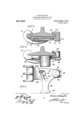
- Figure 1 is an end elevation of a rail, showing the anti-creeping device in place thereon.
- Fig. 9 is a plan view of the device with the rail indicated in dotted lines.
- Fig. 3 is a sectional view through the device, showingthe same in place on a rail base.
- Fig. 4 1s a view in elevation of a modified four. of construction.
- Fig. 5 is a plan view of the modified structure.
- a rail gripping jaw 6 is employe 7 for the reception of one edge of the base flange of the rail, and also having a base urn-1.8 that is suitably reinforced and extends transversely beneath the rail.
- This base arm 8 is provided in its free end with a longitudinall disposed open-ended bearing slot 9, and is also provided between the slot and the jaw with a plurality of transversely disposed curved bearing shoulders 10 arranged in tooth-like formation.
- shoulders or teeth while concentric to each other, are preferably struck from a ccnterindicated at.11 that is disposed at one side jo'f the pivotal oint of arm 16.
- a second-member gf the evice is in the form of another rail gripping jaw 12 having afla'ring engaging recess 13 tolre- Specification of Letters Patent.
- the jaw 12 has a dependin fulcrum pin 14 that'is rot-atably and slida bly' journaled in the slot 9, said'fulcrum pin having a head 15 of greater diameter than the cross section of the slot so as to prevent the base arm Sulropping from the pin.
- This jaw 19. also has an inwardly extending swinging arm 16 that overlies the base arm 8, and has formed on its under side, a plurality of transversely disposed curved bearing shoulders or teeth 17 arranged to cooperate with theshonlders or-teeth 10.
- the rail engaging jaw (3 is placed upon one side of the base flange of the ,rail, and the oppositejaw is engaged with the opposite portion of said rail flange, the shoulders or teeth 10 and 17 being interlocked.
- the device is then moved toward the tie until the bearing foot 20 engages the side of said tie.
- FIGS. 4 and 5 are presented.
- crum pin 26 that operates in' the slot 23, and also employsa swing arm 27 overlying the basearm 22 and having an eccentric slot 28 in which the pin 24 is engaged.
- the said -slot 28 is formed at one end with a lateral slot extension 28 which lies in the same general direction as the bearing slot 23 and is sufiiciently long to permit the element 25 to clear the edge of the rail flange when ap lying the device to the track.
- the arm 2 is extended to form an actuating arm 29 provided with a terminal bearing foot 30 that en ages the tie.
- the operation of this modifi I evice is the same as that of the form .already'described, but it will be noted that this particular embodiment isnot adjustable to rails of difii'erent sizes.
- rail-embracing elements relatively slidable toward each other, and also relatively rotatable, and coactin means carried by the elements for effecting their relative sliding movement by the relative rotary movement.
- a relatively fixed rail-engaging jaw 'a second jaw havin a swinging movement on a fulcrum slida le transversely of the rail, and
- An anti-creeping device for rails comprising a air of rail gripping elements, one of which has a fulcrum t at is shiftable'on the other transversely of the rail.
- An anti creepingdevice for rails comprising a pair of opposing rail gripping eleone of whic has a fulcrum that is shiftable on the other transversely of the rail, and means for efi'ecting the relative shifting of the rail gripping elements through longitudinal movement of the rail.
- a pair of rail-gripping elements one of which has a fulcrum that is shiftableon the other transversely of the rail, and means for effectlIilig a turning movement of said element, and e ecting the said shifting movement of its fulcrum.
- rail engaging jaw having a base, a swinging rail engaging member shiftabl fulcrumed to said base and also having as iding bearin engagement with the base which is eccentric to the fulcrum.
- a rail-engaging jaw having a base provided with a s 0t, and a swin ing rail-engaging jaw having a fulcrum slidable in .the-slot and also having a sliding bearing eccentric to the fulcrum.
- a rail-gm ping element having a sliding fulcrum on the first element and also having a sliding bearing thereon that is eccentric to the fulcrum.
- a rail-engaging jaw having a base that extends transversely beneath the rail and provided at its free end with a longitudinal slot
- a swinging rail-embracing jaw having a 'ful crum slidable in the slot and also having a. bearing on said-basethat is eccentric to the fulcrum, said swinging jaw also having a tie engaging actuating arm.
- rail-gripping element having a raiLengagmg portion, and a second rall gripping element pivoted thereon and having its axis of movement adjustable toward and from the rail en aging portion to adjust the device to rails o diflerent sizes.
- rail-gripping jaw having a base, and a second rail gripping jaw pivotally mounted thereon and having its axis of movement adjustable toward and iromthe first jaw to adjust the device to-rails of difierent sizes.
- both of said jaws also having a plurality of interlocking s iding bearings disposed eccentric to the fulcrum and which are adiustably engaged to adjust the device to rai s of different sizes.
- 5 rail-gripping jaw having a base that extends transversely beneath the rail, said base being provided with a longitudinal terminal slot, and a plurality'of concentrically disposed bearing shoulders, and a second ra1l grippin jaw arranged opposite to the first jaw and having a fulcrum in the slot of-the base, said second jaw also having bearing shoul; ders adapted to en age with-the diflerenli bearing shoulders o the base, said interen- ⁇ gaged shoulders being eccentric to said fulcrum.
- An anti-creeping device for rails comprising a pair 'of opposite relatively swinging and relatively shiftable rail-gripping 20 elements having members provided with slidably interlocked shoulders, the shoulders of one member being struck on a radius having a difi'erent' center from the radius for the.
- a base tha extends V beneath the rail, said ase being provlded so with a terminal longitudinal slot and a pl u- 'rality of transverse curved bearing shoulders,- and a second rail gri ping jaw having a fulcrum journ'aled and s idable longitudinally in the slot, said second jaw havin .
Landscapes
- Engineering & Computer Science (AREA)
- Mechanical Engineering (AREA)
- Architecture (AREA)
- Civil Engineering (AREA)
- Structural Engineering (AREA)
- Machines For Laying And Maintaining Railways (AREA)
Description
B. WOLHAUPTER.
ANTIGREEPING DEVICE FOR RAILS.
APPLICATION 11mm r23. 1, 1910.
Patented May 3, 1910.
2 SHEETS-SHEET 1.
v JNVENTOR B. WOLHAUPTEBJ. ANTIGREEPING DEVICE FOR RAILS.
APPLICATION FILED ran. 1, 1910.
957,023. Patented May 3, 1910.-
I 2 SHEETS-SHEET 2.
EEC a5 INVENTORY- having a tapered socket .plicable to rails already BENJAMIN WOLHAUPTER,
OF NEW YORK, N. Y.
ANTICR EEPING DEVICE FOR RAILS.
Application flied February 1, 1910,
'York and State of New York, have invented certain new and useful Improvements m Anticreeping Devices for Balls, of which It'he following is a specification.
The present invention relates to means for anchoring railroad rails in order to prevent their creepinglongitudinally, and it is one of the objects of the invention to provide a simple and cheap device of few parts that will effectively hold the rail, is readily apin use without in any manner changing the latter, and'when position, will effectively maintain such position.
Another object of the invention is to provide an anti-creeping device or anchor that can be applied to rails of different cross sectional areas.
Two embodiments of the invention are illustrated in the accompanying drawings, wherein 2 Figure 1 is an end elevation of a rail, showing the anti-creeping device in place thereon. Fig. 9 is a plan view of the device with the rail indicated in dotted lines. Fig. 3 is a sectional view through the device, showingthe same in place on a rail base. Fig. 4 1s a view in elevation of a modified four. of construction. Fig. 5 is a plan view of the modified structure.
Like references designate corresponding partsin the several figures of the drawings.
In the embodiment disclosed in Figs. 1, 2 and 3, a rail gripping jaw 6 is employe 7 for the reception of one edge of the base flange of the rail, and also having a base urn-1.8 that is suitably reinforced and extends transversely beneath the rail. This base arm 8 is provided in its free end with a longitudinall disposed open-ended bearing slot 9, and is also provided between the slot and the jaw with a plurality of transversely disposed curved bearing shoulders 10 arranged in tooth-like formation.
These shoulders or teeth, while concentric to each other, are preferably struck from a ccnterindicated at.11 that is disposed at one side jo'f the pivotal oint of arm 16. A second-member gf the evice is in the form of another rail gripping jaw 12 having afla'ring engaging recess 13 tolre- Specification of Letters Patent.
Patented May 3, 1910.
Serial No. 541,231.
edge of the base flange of the rail, the jaws l2 and 6 thus being disposed in opposition to each other. The jaw 12 has a dependin fulcrum pin 14 that'is rot-atably and slida bly' journaled in the slot 9, said'fulcrum pin having a head 15 of greater diameter than the cross section of the slot so as to prevent the base arm Sulropping from the pin. This jaw 19. also has an inwardly extending swinging arm 16 that overlies the base arm 8, and has formed on its under side, a plurality of transversely disposed curved bearing shoulders or teeth 17 arranged to cooperate with theshonlders or-teeth 10. These shoulders or teeth 17, while concentric with respect to each other, are like the elements 10 eccentric to the ful- 'crum or pivot 1*t;-'in other words, being struck from a center indicated at 18. It will thus be evident that if the arm 16 swings upon 'the base arm 8, the com-ting shoulders or teeth 10 and 17, while permitting the rotation of the jaw 12, will draw the latter and 'the j aw 6 toward each other, the fulcrum 14 sliding longitudinally in the slot 9 while, this action is taking place; In order to secure this movement, upon the attem ted longitudinal movementor creeping of tie rail, the arm 16 has an outstanding ofl'set 19 provided with a curved bearing foot 20 that. is adapted to be placed against the side of the tie.
In applying the device, the rail engaging jaw (3 is placed upon one side of the base flange of the ,rail, and the oppositejaw is engaged with the opposite portion of said rail flange, the shoulders or teeth 10 and 17 being interlocked. The device is then moved toward the tie until the bearing foot 20 engages the side of said tie. With this device, therefore, it will be obvious that if there is any tendency 'onthe part of the rail to creep longitudinally, the arm 16 will swing, thereby causing a sliding movement of the shoulders 17 upon and against the shoulders 10. This sliding movement will cited; the sliding of the fulcrum with its jaw, causing the two jaws to effectively grip the rail base and prevent its movement. It will readily-appear that the invention can be applied towns of difleren cross sectional areas, inasmuch asitsis l v:necessary to enga e the shoulders 17 with the proper shonl ers 10, the fulcrum readily cei re the opposite consequently with a longitudin disengaged in order to make the necessary adjustment. It is on account of the a lication of this device to rails havingdi erent widths that the shoulders 10 and 17 have difierent center points 11 and 18..
As an illustration of how the structure may be modified, Figs. 4 and 5 are presented.
; crum pin 26 that operates in' the slot 23, and also employsa swing arm 27 overlying the basearm 22 and having an eccentric slot 28 in which the pin 24 is engaged. The said -slot 28 is formed at one end with a lateral slot extension 28 which lies in the same general direction as the bearing slot 23 and is sufiiciently long to permit the element 25 to clear the edge of the rail flange when ap lying the device to the track. The arm 2 is extended to form an actuating arm 29 provided with a terminal bearing foot 30 that en ages the tie. The operation of this modifi I evice is the same as that of the form .already'described, but it will be noted that this particular embodiment isnot adjustable to rails of difii'erent sizes. v p
From the foregoing, it is thought that the construction, operation, and many advantages of the herein described invention will be apparent to those skilled in the art w'it-hout further description, and it will be understood that various changes in thesize,
shape, proportion andminor details of con. struction may be resorted to without depart-' ing from the spirit or sacrificing any of the advantages of the invention.
claim:
1. In an anti-creeping device for rails,
rail-embracing elements relatively slidable toward each other, and also relatively rotatable, and means for eflI'ectin'g both their said rotatable and sliding movements.
2. In an anti-creeping device for rails, rail-embracing elements relatively slidable toward each other, and also relatively rotatable, and coactin means carried by the elements for effecting their relative sliding movement by the relative rotary movement.
3. In an anti-creeping device for rails, a relatively fixed rail-engaging jaw, 'a second jaw havin a swinging movement on a fulcrum slida le transversely of the rail, and
means 'for eifecting the movement of the sec M relat-ively swinging and relatively shiftablerail gripping aws having an .lnterlocked ond jaw.
4. An anti-creeping device for rails, comprising a air of rail gripping elements, one of which has a fulcrum t at is shiftable'on the other transversely of the rail.
5. An anti creepingdevice for rails comprising a pair of opposing rail gripping eleone of whic has a fulcrum that is shiftable on the other transversely of the rail, and means for efi'ecting the relative shifting of the rail gripping elements through longitudinal movement of the rail.
6. In an anti-creeping device for rails, a pair of rail-gripping elements, one of which has a fulcrum that is shiftableon the other transversely of the rail, and means for effectlIilig a turning movement of said element, and e ecting the said shifting movement of its fulcrum.
.7.In an anti-creeping device for rails, a
rail engaging jaw havin a base provided with a slot, and a swingm rail engagin member having a fulcrum s iiftable in sai slot.
8. In an anti-creeping device for rails, a
rail engaging jaw having a base, a swinging rail engaging member shiftabl fulcrumed to said base and also having as iding bearin engagement with the base which is eccentric to the fulcrum.
9. In an anti creeping' device for rails, a rail-engaging jaw having a base provided with a s 0t, and a swin ing rail-engaging jaw having a fulcrum slidable in .the-slot and also having a sliding bearing eccentric to the fulcrum.
10. In an anti-creeping device for rails, a rail-gm ping element, and a second swingm rai gripping element having a sliding fulcrum on the first element and also having a sliding bearing thereon that is eccentric to the fulcrum.
11. In an anti-creeping device for rails, a rail-engaging jaw having a base that extends transversely beneath the rail and provided at its free end with a longitudinal slot, and
a swinging rail-embracing jaw having a 'ful crum slidable in the slot and also having a. bearing on said-basethat is eccentric to the fulcrum, said swinging jaw also having a tie engaging actuating arm.
12. In an anti-creeping device for rails, a
rail-gripping element having a raiLengagmg portion, and a second rall gripping element pivoted thereon and having its axis of movement adjustable toward and from the rail en aging portion to adjust the device to rails o diflerent sizes.
. 13. In an anti-creeping device for rails, a
rail-gripping jaw having a base, and a second rail gripping jaw pivotally mounted thereon and having its axis of movement adjustable toward and iromthe first jaw to adjust the device to-rails of difierent sizes.
14.In an anti-creeping device for rails,
and both of said jaws also having a plurality of interlocking s iding bearings disposed eccentric to the fulcrum and which are adiustably engaged to adjust the device to rai s of different sizes.
16. In an anti-creeping device for rails, a
5 rail-gripping jaw having a base that extends transversely beneath the rail, said base being provided with a longitudinal terminal slot, and a plurality'of concentrically disposed bearing shoulders, and a second ra1l grippin jaw arranged opposite to the first jaw and having a fulcrum in the slot of-the base, said second jaw also having bearing shoul; ders adapted to en age with-the diflerenli bearing shoulders o the base, said interen-\ gaged shoulders being eccentric to said fulcrum. a p
'17. An anti-creeping device for rails comprising a pair 'of opposite relatively swinging and relatively shiftable rail-gripping 20 elements having members provided with slidably interlocked shoulders, the shoulders of one member being struck on a radius having a difi'erent' center from the radius for the.
shoulders of the other member, and both of movement of the elements.
18. In an anti-creeping device {arail gripping jaw havin a base tha extends V beneath the rail, said ase being provlded so with a terminal longitudinal slot and a pl u- 'rality of transverse curved bearing shoulders,- and a second rail gri ping jaw having a fulcrum journ'aled and s idable longitudinally in the slot, said second jaw havin .a 35 plurality of curved bearingj'shoul ders: 1's-, posed eccentrically to the ulcriim and arran ed to engage the different shoulders of the ase, said second jaw furthermore having an outstanding arm provided with a tie- 40 engaging foot,
-In.testimony whereof I hereunto afiix my. signature in the presence of two witnesses.
BENJAMIN WQLHAUPTER.
Witnesses:
Geo. W. WRIGHT; WALTER S. OGILVY.
Priority Applications (1)
| Application Number | Priority Date | Filing Date | Title |
|---|---|---|---|
| US54123110A US957023A (en) | 1910-02-01 | 1910-02-01 | Anticreeping device for rails. |
Applications Claiming Priority (1)
| Application Number | Priority Date | Filing Date | Title |
|---|---|---|---|
| US54123110A US957023A (en) | 1910-02-01 | 1910-02-01 | Anticreeping device for rails. |
Publications (1)
| Publication Number | Publication Date |
|---|---|
| US957023A true US957023A (en) | 1910-05-03 |
Family
ID=3025426
Family Applications (1)
| Application Number | Title | Priority Date | Filing Date |
|---|---|---|---|
| US54123110A Expired - Lifetime US957023A (en) | 1910-02-01 | 1910-02-01 | Anticreeping device for rails. |
Country Status (1)
| Country | Link |
|---|---|
| US (1) | US957023A (en) |
-
1910
- 1910-02-01 US US54123110A patent/US957023A/en not_active Expired - Lifetime
Similar Documents
| Publication | Publication Date | Title |
|---|---|---|
| US1536359A (en) | Rail or track clamp | |
| US2593956A (en) | Car replacer | |
| US910132A (en) | Railroad-track brace. | |
| US1231718A (en) | Road-bed for railroads. | |
| US1292873A (en) | Rail-anchor. | |
| US1180890A (en) | Anticreeper for railroad-rails. | |
| US1555686A (en) | Device for balling steel rails for track | |
| US1676982A (en) | Railroad-tie spacer | |
| US6042A (en) | Bail and wheel for turning curves of railroads | |
| US1292756A (en) | Rail-stay. | |
| US1185701A (en) | Trip for litter-carriers. | |
| US770213A (en) | Track-gage. | |
| US724437A (en) | Wagon wrench and jack. | |
| US1194673A (en) | Assiotok | |
| US1644178A (en) | One-piece spring rail anchor | |
| US854435A (en) | Rail-anticreeper. | |
| US1771819A (en) | Mine-tie clip | |
| US1491507A (en) | Car-guiding device | |
| US1462162A (en) | Rail anchor | |
| US1358726A (en) | Rail-anchor | |
| US1724182A (en) | Rail anticreep and antispread anchor | |
| US1464235A (en) | Safety railroad joint | |
| US1204659A (en) | Anticreeper. | |
| US1205945A (en) | Rail-anchor. | |
| US1005278A (en) | Clamp for securing railroad-rails to metal ties. |