US9561582B2 - Connector - Google Patents

Connector Download PDF

Info

Publication number
US9561582B2
US9561582B2 US14/875,237 US201514875237A US9561582B2 US 9561582 B2 US9561582 B2 US 9561582B2 US 201514875237 A US201514875237 A US 201514875237A US 9561582 B2 US9561582 B2 US 9561582B2
Authority
US
United States
Prior art keywords
abutting
rod body
section
socket
connecting rod
Prior art date
Legal status (The legal status is an assumption and is not a legal conclusion. Google has not performed a legal analysis and makes no representation as to the accuracy of the status listed.)
Expired - Fee Related
Application number
US14/875,237
Other versions
US20160107299A1 (en
Inventor
Chung-Liang HSU
Current Assignee (The listed assignees may be inaccurate. Google has not performed a legal analysis and makes no representation or warranty as to the accuracy of the list.)
CHUNG TAAN INDUSTRIAL Co Ltd
Original Assignee
CHUNG TAAN INDUSTRIAL Co Ltd
Priority date (The priority date is an assumption and is not a legal conclusion. Google has not performed a legal analysis and makes no representation as to the accuracy of the date listed.)
Filing date
Publication date
Application filed by CHUNG TAAN INDUSTRIAL Co Ltd filed Critical CHUNG TAAN INDUSTRIAL Co Ltd
Assigned to CHUNG TAAN INDUSTRIAL CO., LTD. reassignment CHUNG TAAN INDUSTRIAL CO., LTD. ASSIGNMENT OF ASSIGNORS INTEREST (SEE DOCUMENT FOR DETAILS). Assignors: HSU, CHUNG-LIANG
Publication of US20160107299A1 publication Critical patent/US20160107299A1/en
Application granted granted Critical
Publication of US9561582B2 publication Critical patent/US9561582B2/en
Expired - Fee Related legal-status Critical Current
Anticipated expiration legal-status Critical

Links

Images

Classifications

    • BPERFORMING OPERATIONS; TRANSPORTING
    • B25HAND TOOLS; PORTABLE POWER-DRIVEN TOOLS; MANIPULATORS
    • B25BTOOLS OR BENCH DEVICES NOT OTHERWISE PROVIDED FOR, FOR FASTENING, CONNECTING, DISENGAGING OR HOLDING
    • B25B23/00Details of, or accessories for, spanners, wrenches, screwdrivers
    • B25B23/0064Means for adjusting screwing depth
    • BPERFORMING OPERATIONS; TRANSPORTING
    • B25HAND TOOLS; PORTABLE POWER-DRIVEN TOOLS; MANIPULATORS
    • B25BTOOLS OR BENCH DEVICES NOT OTHERWISE PROVIDED FOR, FOR FASTENING, CONNECTING, DISENGAGING OR HOLDING
    • B25B23/00Details of, or accessories for, spanners, wrenches, screwdrivers
    • B25B23/0007Connections or joints between tool parts
    • B25B23/0035Connection means between socket or screwdriver bit and tool
    • BPERFORMING OPERATIONS; TRANSPORTING
    • B25HAND TOOLS; PORTABLE POWER-DRIVEN TOOLS; MANIPULATORS
    • B25BTOOLS OR BENCH DEVICES NOT OTHERWISE PROVIDED FOR, FOR FASTENING, CONNECTING, DISENGAGING OR HOLDING
    • B25B23/00Details of, or accessories for, spanners, wrenches, screwdrivers
    • B25B23/02Arrangements for handling screws or nuts
    • B25B23/08Arrangements for handling screws or nuts for holding or positioning screw or nut prior to or during its rotation
    • B25B23/12Arrangements for handling screws or nuts for holding or positioning screw or nut prior to or during its rotation using magnetic means
    • BPERFORMING OPERATIONS; TRANSPORTING
    • B25HAND TOOLS; PORTABLE POWER-DRIVEN TOOLS; MANIPULATORS
    • B25BTOOLS OR BENCH DEVICES NOT OTHERWISE PROVIDED FOR, FOR FASTENING, CONNECTING, DISENGAGING OR HOLDING
    • B25B21/00Portable power-driven screw or nut setting or loosening tools; Attachments for drilling apparatus serving the same purpose

Definitions

  • the present invention relates to a connector for tool.
  • a material which is soft and easily cracked such as a wood board or a plastic board
  • the present invention has arisen to mitigate and/or obviate the afore-described disadvantages.
  • the major object of the present invention is to provide a connector, when a rod body of the connector screws an object to be screwed to a configuration face and the configuration face abuts against an abutting assembly of the connector, the rod body of the connector and a connecting rod connected with the rotational driving tool become rotatable relative to each other, and the screw cannot be rotated and screwed into the configuration face.
  • a connector including a rod body, at least one detent, an abutting assembly, a first elastic member and a connecting rod.
  • Two opposite ends of the rod body are respectively formed with an assembling portion for a tool head to be assembled thereto and an insertion groove.
  • the insertion groove has at least one restraining section and at least one radially-enlarged section which are neighboring to each other and a receiving section, and a smallest radial dimension of the at least one radially-enlarged section is greater than a largest radial dimension of the at least one restraining section.
  • the rod body is formed with at least one through hole which communicates with the receiving section.
  • the at least one detent is received in the at least one through hole and partially projectable into the insertion groove.
  • the abutting assembly and the rod body are positioningly restrained relative to each other, the abutting assembly is sleeved outside the rod body, the at least one detent is sandwiched between the abutting assembly and the rod body, and the abutting assembly is movable relative to the rod body between an abutting position and a releasing position.
  • An inner side of the abutting assembly has a protrusion and a recess.
  • the first elastic member abuts against between the rod body and the abutting assembly and biases the abutting assembly toward the abutting position normally.
  • the connecting rod further includes at least one abutting section which is radially protrudes thereon and an annular groove. Each said abutting section is non-round and abuttable against an inner wall of one said restraining section circumferentially, and the connecting rod is axially movable relative to the rod body to a comoving position or an idling position.
  • each said abutting section corresponds to and circumferentially abuts against the inner wall of one said restraining section
  • FIG. 1 is a perspective drawing of a preferred embodiment of the present invention
  • FIG. 2 is a breakdown drawing of the preferred embodiment of the present invention.
  • FIG. 3 is another breakdown drawing of the preferred embodiment of the present invention.
  • FIGS. 4 to 6 are cross-sectional drawings of the preferred embodiment of the present invention in operation
  • FIG. 7 is a breakdown drawing of another preferred embodiment of the present invention.
  • FIGS. 8 and 9 are cross-sectional drawings of another preferred embodiment of the present invention in operation.
  • a connector 1 includes a rod body 2 , at least one detent 3 , an abutting assembly 4 , a first elastic member 5 and a connecting rod 6 .
  • the rod body 2 Two ends of the rod body 2 are respectively formed with an assembling portion 21 for a tool head 7 to be assembled thereto (as shown in FIG. 4 ) and an insertion groove 22 .
  • the insertion groove 22 has at least one restraining section 221 and at least one radially-enlarged section 222 which are neighboring to each other and a receiving section 223 , and a smallest radial dimension of the at least one radially-enlarged section 222 is greater than a largest radial dimension of the at least one restraining section 221 .
  • the rod body 2 is formed with at least one through hole 224 which communicates with the receiving section 223 , and in this embodiment, a number of the through holes 224 is three.
  • the at least one detent 3 is received in the through holes 224 and partially projectable into the insertion groove 22 .
  • a number of the detents 3 corresponds to the number of the through holes 224 .
  • the tool head 7 is a hexagonal screwdriver
  • the assembling portion 21 is hexagonal; however, in other embodiments, the tool head and the assembling portion may be in other shapes.
  • the abutting assembly 4 and the rod body 2 can be positioningly restrained relative to each other, and the abutting assembly 4 is sleeved outside the rod body 2 so that the detents 3 are sandwiched between the abutting assembly 4 and the rod body 2 .
  • the abutting assembly 4 is movable relative to the rod body 2 between an abutting position and a releasing position, and an inner side of the abutting assembly 4 has a protrusion 411 and a recess 412 .
  • the abutting assembly 4 includes a socket 41 and an abutting member 42 , the socket 41 is sleeved outside the rod body 2 , an inner side of the socket 41 is formed with the protrusion 411 and the recess 412 , an outer side of the socket 41 is provided with a first threaded section 413 , an end of the abutting member 42 is axially adjustably screwed to the first threaded section 413 of the socket 41 , and a relative position of the abutting member 42 and the socket 41 is adjustable through screwing the abutting member 42 and the socket 41 relative to each other.
  • the first elastic member 5 abuts against between the rod body 2 and the abutting assembly 4 and biases the abutting assembly 4 toward the abutting position normally.
  • the rod body 2 further includes a retaining ring 23
  • the abutting assembly 4 further includes a loop 43 .
  • the retaining ring 23 is arranged around an outer side of the rod body 2
  • the loop 43 is arranged around the inner side of the abutting assembly 4
  • the first elastic member 5 abuts against between the retaining ring 23 and the loop 43
  • the retaining ring 23 is located between the loop 43 and the protrusion 411 so that the socket 41 is non-disengageable from the rod body 2 .
  • the retaining ring 23 is a C-shaped fastening member; and in other embodiments, the retaining ring 23 may be a round annular fastening member.
  • the loop 43 may also be a C-shaped fastener arranged around the inner side of the abutting assembly 4 .
  • the connector 1 may further include a surrounding member 8 .
  • the surrounding member 8 is axially movably arranged on and slidable relative to the rod body 2 , a front end of the socket 8 has a magnetic ring 81 for the tool head 7 to be disposed therethrough so that the magnetic ring 81 of the surrounding member 8 can be used to magnetically suck a screw 71 on the tool head 7 (as shown in FIG. 4 ) to prevent the screw 71 from falling off.
  • a front end of the rod body 2 is provided with a second threaded section 24
  • a rear end of the surrounding member 8 is screwed to the second threaded section 24
  • the surrounding member 8 is positioningly connected to the rod body 2 .
  • the connector 1 may further include a second elastic member 51 which is disposed around the rod body 2 , and two ends of the second elastic member 51 respectively abut against the rear end of the surrounding member 8 and a shoulder portion 26 of the rod body 2 to bias the surrounding member 8 toward a front end of the abutting member 42 for sucking the screw 71 .
  • the screw 71 may be other fixing elements.
  • the connecting rod 6 further includes at least one abutting section 61 which radially protrudes thereon and an annular groove 62 .
  • Each said abutting section 61 is non-round and abuts against an inner wall of one said restraining section 221 circumferentially, and the connecting rod 6 is axially movable relative to the rod body 2 to a comoving position or an idling position.
  • the connecting rod 6 includes two said abutting sections 61
  • the insertion groove 22 includes two said radially-enlarged sections 222 and two said restraining sections 221 .
  • Each said abutting section 61 is a polygonal protrusion
  • each said restraining section 221 is a polygonal annular recess corresponding to the polygonal protrusion.
  • each said abutting section 61 is a hexagonal protrusion
  • each said restraining section 221 is a hexagonal recess corresponding to the hexagonal protrusion; and in other embodiments, each said abutting section 61 and each said restraining section 221 may be in other shapes.
  • FIGS. 4 to 6 Please further refer to FIGS. 4 to 6 .
  • the protrusion 411 abuts against the detents 3
  • the detents 3 partially protrude into the annular groove 62 to restrain the connecting rod 6 from axially moving relative to the rod body 2
  • each said abutting section 61 corresponds to and circumferentially abuts against the inner wall of one said restraining section 221 ;
  • the rotational driving tool 9 rotates the connecting rod 6 .
  • the protrusion 411 abuts against the detents 3
  • the detents 3 partially protrude into the annular groove 62 to restrain the connecting rod 6 from axially moving relative to the rod body 2
  • each said abutting section 61 corresponds to and circumferentially abuts against the inner wall of one said restraining section 221 so that the connecting rod 6 comoves with the rod body 2 ; therefore, the tool head 7 which is assembled to the assembling portion 21 can drive the screw 71 arranged on the tool head 7 to rotate so as to screw the screw 71 to a configuration face A.
  • the abutting assembly 4 is pushed to the releasing position, the detents 3 retreat into the recess 412 , the connecting rod 6 is axially movable relative to the rod body 2 to the idling position, each said abutting section 61 moves axially to correspond to one said radially-enlarged section 222 so that the connecting rod 6 is rotatable relative to the rod body 2 , the rod body 2 is unrotatable, and the tool head 7 and the screw 71 cannot be rotated nor be screwed into the configuration face A.
  • the relative position of the abutting member 42 and the screw 71 may be adjusted by adjusting an axial position of the abutting member 42 to prevent a screw head of the screw 71 from being overly screwed into the configuration face A and from damaging a structure of the configuration face A and cracking of the configuration face A.
  • the abutting assembly 4 may further include a positioning member 44 , and the positioning member 44 is screwed to the first threaded section 413 and located between the abutting member 42 and the connecting rod 6 to prevent the abutting member 42 form sliding relative to the socket 41 when the abutting member 42 abuts against the configuration face A.
  • the insertion groove 22 may further include a tapered section 225 which is tapered toward a front end of the insertion groove 22 , and the tapered section 225 is provided in a front end of the receiving section 223 (as shown in FIG. 3 ).
  • the insertion groove 22 may further include a rolling ball 25 , and the rolling ball 25 is arranged in the tapered section 225 .
  • the rolling ball 25 abuts against between the tapered section 225 and the connecting rod 6 and point-contacts the connecting rod 6 , the tapered section 225 can decrease a friction between the connecting rod 6 and the insertion groove 22 ; therefore, the connecting rod 6 is rotatable relative to the insertion groove 22 , and the connecting rod 6 can be prevented from abutting against an end of the insertion groove 22 and from being abraded.
  • the insertion groove may be provided without the rolling ball, and the connecting rod 6 can still smoothly rotate within the insertion groove.
  • An abutting assembly 4 A includes a socket 41 A and an abutting member 42 A.
  • the socket 41 A is sleeved outside the rod body 2 , an inner side of the socket 41 A has the protrusion 411 and the recess 412 , and an outer side of the socket 41 A is provided with a first threaded section 413 A.
  • An end of the abutting member 42 A is axially adjustably screwed to the first threaded section 413 A of the socket 41 A.
  • the abutting assembly 4 A may further include a positioning member 44 A, and the positioning member 44 A is slidably sleeved to the abutting member 42 A.
  • An outer wall of the socket 41 A has at least one slot 414 on a direction parallel to an axial direction of the socket 41 A, and a circumferential wall of the abutting member 42 A has at least one foot portion 421 which corresponds to the at least one slot 414 in shape.
  • the positioning member 44 A When each said foot portion 421 corresponds to one said slot 414 , the positioning member 44 A is slidable toward the at least one foot portion 421 to positioningly restrain each said foot portion 421 in one said slot 414 , and the abutting member 42 A and the socket 41 A are non-screwable relative to each other; therefore, the positioning member 44 A can prevent the abutting member 42 A from sliding relative to the socket 41 A when the abutting member 42 A abuts against the configuration face A.
  • An upper section of an outer side of the socket 41 A is provided with the first threaded section 413 A, and an lower section of the outer side of the socket 41 A is greater than the first threaded section 413 A in outer radial dimension so as to effectively positioningly restrain each said foot portion 421 .
  • a distal end of each said foot portion 421 has a protrusive portion 422 ; therefore, when the positioning member 44 A slides to the at least one foot portion 421 , the protrusive portion 422 of each said foot portion 421 abuts against the positioning member 44 A to prevent the positioning member 44 A from falling off from the abutting member 42 A.

Abstract

A connector includes a rod body, at least one detent, an abutting assembly, a first elastic member and a connecting rod. An insertion groove of the rod body has at least one restraining section, at least one radially-enlarged section and a receiving section, and the rod body has at least one through hole communicating with the receiving section. The detent is received in the through hole and partially protrudes into the insertion groove. The abutting assembly is sleeved outside the rod body, and the detent is sandwiched between the abutting assembly and rod body. The first elastic member abuts against the rod body and abutting assembly to bias the abutting assembly toward an abutting position. The connecting rod further includes at least one abutting section protruding radially and an annular groove, and is axially movable relative to the rod body to comoving or idling position.

Description

BACKGROUND OF THE INVENTION
Field of the Invention
The present invention relates to a connector for tool.
Description of the Prior Art
Usually, when a user assembles a material which is soft and easily cracked, such as a wood board or a plastic board, s/he screws a screw into the material with a rotational driving tool to prevent the material from cracking when the material is assembled (for example, a nail is knocked into the wood board).
However, in the prior art, when the screw is screwed into the material with the rotational driving tool, a screw head of the screw is often buried under a surface of the material while the rotational driving tool is still rotating, and the screw head which is buried deep into the material may cause the material to crack or make the surface of the material uneven.
The present invention has arisen to mitigate and/or obviate the afore-described disadvantages.
SUMMARY OF THE INVENTION
The major object of the present invention is to provide a connector, when a rod body of the connector screws an object to be screwed to a configuration face and the configuration face abuts against an abutting assembly of the connector, the rod body of the connector and a connecting rod connected with the rotational driving tool become rotatable relative to each other, and the screw cannot be rotated and screwed into the configuration face.
To achieve the above and other objects, a connector is provided, including a rod body, at least one detent, an abutting assembly, a first elastic member and a connecting rod. Two opposite ends of the rod body are respectively formed with an assembling portion for a tool head to be assembled thereto and an insertion groove. The insertion groove has at least one restraining section and at least one radially-enlarged section which are neighboring to each other and a receiving section, and a smallest radial dimension of the at least one radially-enlarged section is greater than a largest radial dimension of the at least one restraining section. The rod body is formed with at least one through hole which communicates with the receiving section. The at least one detent is received in the at least one through hole and partially projectable into the insertion groove. The abutting assembly and the rod body are positioningly restrained relative to each other, the abutting assembly is sleeved outside the rod body, the at least one detent is sandwiched between the abutting assembly and the rod body, and the abutting assembly is movable relative to the rod body between an abutting position and a releasing position. An inner side of the abutting assembly has a protrusion and a recess. The first elastic member abuts against between the rod body and the abutting assembly and biases the abutting assembly toward the abutting position normally. An end of the connecting rod is adjustably inserted into the insertion groove, and the other end of the connecting rod is for connection with a rotational driving tool. The connecting rod further includes at least one abutting section which is radially protrudes thereon and an annular groove. Each said abutting section is non-round and abuttable against an inner wall of one said restraining section circumferentially, and the connecting rod is axially movable relative to the rod body to a comoving position or an idling position. Wherein, when the abutting assembly is in the abutting position and the connecting rod is in the comoving position, the protrusion abuts against the at least one detent to make the at least one detent partially protrude into the annular groove to restrain the connecting rod from axially moving relative to the rod body, and each said abutting section corresponds to and circumferentially abuts against the inner wall of one said restraining section; when the abutting assembly is in the releasing position and the connecting rod is in the idling position, the recess allows the at least one detent to retreat thereinto, the connecting rod is axially movable relative to the rod body, and each said abutting section corresponds to one said radially-enlarged section so that the connecting rod is rotatable relative to the rod body.
The present invention will become more obvious from the following description when taken in connection with the accompanying drawings, which show, for purpose of illustrations only, the preferred embodiment(s) in accordance with the present invention.
BRIEF DESCRIPTION OF THE DRAWINGS
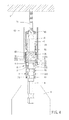
FIG. 1 is a perspective drawing of a preferred embodiment of the present invention;
FIG. 2 is a breakdown drawing of the preferred embodiment of the present invention;
FIG. 3 is another breakdown drawing of the preferred embodiment of the present invention;
FIGS. 4 to 6 are cross-sectional drawings of the preferred embodiment of the present invention in operation;
FIG. 7 is a breakdown drawing of another preferred embodiment of the present invention; and
FIGS. 8 and 9 are cross-sectional drawings of another preferred embodiment of the present invention in operation.
DETAILED DESCRIPTION OF THE PREFERRED EMBODIMENTS
The present invention will be clearer from the following description when viewed together with the accompanying drawings, which show, for purpose of illustrations only, the preferred embodiment in accordance with the present invention.
Please refer to FIGS. 1 to 3 for a preferred embodiment of the present invention. A connector 1 includes a rod body 2, at least one detent 3, an abutting assembly 4, a first elastic member 5 and a connecting rod 6.
Two ends of the rod body 2 are respectively formed with an assembling portion 21 for a tool head 7 to be assembled thereto (as shown in FIG. 4) and an insertion groove 22. The insertion groove 22 has at least one restraining section 221 and at least one radially-enlarged section 222 which are neighboring to each other and a receiving section 223, and a smallest radial dimension of the at least one radially-enlarged section 222 is greater than a largest radial dimension of the at least one restraining section 221. The rod body 2 is formed with at least one through hole 224 which communicates with the receiving section 223, and in this embodiment, a number of the through holes 224 is three. The at least one detent 3 is received in the through holes 224 and partially projectable into the insertion groove 22. A number of the detents 3 corresponds to the number of the through holes 224. In this embodiment, the tool head 7 is a hexagonal screwdriver, and the assembling portion 21 is hexagonal; however, in other embodiments, the tool head and the assembling portion may be in other shapes.
The abutting assembly 4 and the rod body 2 can be positioningly restrained relative to each other, and the abutting assembly 4 is sleeved outside the rod body 2 so that the detents 3 are sandwiched between the abutting assembly 4 and the rod body 2. The abutting assembly 4 is movable relative to the rod body 2 between an abutting position and a releasing position, and an inner side of the abutting assembly 4 has a protrusion 411 and a recess 412. Specifically, in this embodiment, the abutting assembly 4 includes a socket 41 and an abutting member 42, the socket 41 is sleeved outside the rod body 2, an inner side of the socket 41 is formed with the protrusion 411 and the recess 412, an outer side of the socket 41 is provided with a first threaded section 413, an end of the abutting member 42 is axially adjustably screwed to the first threaded section 413 of the socket 41, and a relative position of the abutting member 42 and the socket 41 is adjustable through screwing the abutting member 42 and the socket 41 relative to each other.
The first elastic member 5 abuts against between the rod body 2 and the abutting assembly 4 and biases the abutting assembly 4 toward the abutting position normally. Specifically, the rod body 2 further includes a retaining ring 23, the abutting assembly 4 further includes a loop 43. The retaining ring 23 is arranged around an outer side of the rod body 2, the loop 43 is arranged around the inner side of the abutting assembly 4, the first elastic member 5 abuts against between the retaining ring 23 and the loop 43, and the retaining ring 23 is located between the loop 43 and the protrusion 411 so that the socket 41 is non-disengageable from the rod body 2. In this embodiment, the retaining ring 23 is a C-shaped fastening member; and in other embodiments, the retaining ring 23 may be a round annular fastening member. The loop 43 may also be a C-shaped fastener arranged around the inner side of the abutting assembly 4.
In this embodiment, the connector 1 may further include a surrounding member 8. The surrounding member 8 is axially movably arranged on and slidable relative to the rod body 2, a front end of the socket 8 has a magnetic ring 81 for the tool head 7 to be disposed therethrough so that the magnetic ring 81 of the surrounding member 8 can be used to magnetically suck a screw 71 on the tool head 7 (as shown in FIG. 4) to prevent the screw 71 from falling off. Preferably, a front end of the rod body 2 is provided with a second threaded section 24, a rear end of the surrounding member 8 is screwed to the second threaded section 24, and the surrounding member 8 is positioningly connected to the rod body 2. Specifically, preferably, in this embodiment, the connector 1 may further include a second elastic member 51 which is disposed around the rod body 2, and two ends of the second elastic member 51 respectively abut against the rear end of the surrounding member 8 and a shoulder portion 26 of the rod body 2 to bias the surrounding member 8 toward a front end of the abutting member 42 for sucking the screw 71. In other embodiments, the screw 71 may be other fixing elements.
An end of the connecting rod 6 is adjustably inserted into the insertion groove 22, and the other end of the connecting rod 6 is for connection with a rotational driving tool 9. The connecting rod 6 further includes at least one abutting section 61 which radially protrudes thereon and an annular groove 62. Each said abutting section 61 is non-round and abuts against an inner wall of one said restraining section 221 circumferentially, and the connecting rod 6 is axially movable relative to the rod body 2 to a comoving position or an idling position. Specifically, in this embodiment, the connecting rod 6 includes two said abutting sections 61, the insertion groove 22 includes two said radially-enlarged sections 222 and two said restraining sections 221. Each said abutting section 61 is a polygonal protrusion, and each said restraining section 221 is a polygonal annular recess corresponding to the polygonal protrusion. In this embodiment, each said abutting section 61 is a hexagonal protrusion, and each said restraining section 221 is a hexagonal recess corresponding to the hexagonal protrusion; and in other embodiments, each said abutting section 61 and each said restraining section 221 may be in other shapes.
Please further refer to FIGS. 4 to 6. When the abutting assembly 4 is in the abutting position and the connecting rod 6 is in the comoving position (as shown in FIG. 4), the protrusion 411 abuts against the detents 3, and the detents 3 partially protrude into the annular groove 62 to restrain the connecting rod 6 from axially moving relative to the rod body 2, and each said abutting section 61 corresponds to and circumferentially abuts against the inner wall of one said restraining section 221;
when the abutting assembly 4 is in the releasing position and the connecting rod 6 is in the idling position (as shown in FIG. 6), the recess 412 allows the detents 3 to retreat thereinto, the connecting rod 6 is axially movable relative to the rod body 2, and each said abutting section 61 corresponds to one said radially-enlarged section 222 so that the connecting rod 6 is rotatable relative to the rod body 2.
In addition, in actual practice, when the abutting assembly 4 is in the abutting position and the connecting rod 6 is in the comoving position, the rotational driving tool 9 rotates the connecting rod 6. The protrusion 411 abuts against the detents 3, the detents 3 partially protrude into the annular groove 62 to restrain the connecting rod 6 from axially moving relative to the rod body 2, and each said abutting section 61 corresponds to and circumferentially abuts against the inner wall of one said restraining section 221 so that the connecting rod 6 comoves with the rod body 2; therefore, the tool head 7 which is assembled to the assembling portion 21 can drive the screw 71 arranged on the tool head 7 to rotate so as to screw the screw 71 to a configuration face A. When the screw 71 is screwed to the configuration face A and the configuration A abuts against the abutting member 42 of the abutting assembly 4, the configuration A pushes and abuts the abutting member 42 toward the rotational driving tool 9, the rotational driving tool 9 pushes and abuts the connecting rod 6 toward the tool head 7 (as shown in FIG. 5), the abutting assembly 4 is pushed to the releasing position, the detents 3 retreat into the recess 412, the connecting rod 6 is axially movable relative to the rod body 2 to the idling position, each said abutting section 61 moves axially to correspond to one said radially-enlarged section 222 so that the connecting rod 6 is rotatable relative to the rod body 2, the rod body 2 is unrotatable, and the tool head 7 and the screw 71 cannot be rotated nor be screwed into the configuration face A.
It is to be noted that because the abutting member 42 and the socket 41 are screwed to each other, the relative position of the abutting member 42 and the screw 71 may be adjusted by adjusting an axial position of the abutting member 42 to prevent a screw head of the screw 71 from being overly screwed into the configuration face A and from damaging a structure of the configuration face A and cracking of the configuration face A. Preferably, the abutting assembly 4 may further include a positioning member 44, and the positioning member 44 is screwed to the first threaded section 413 and located between the abutting member 42 and the connecting rod 6 to prevent the abutting member 42 form sliding relative to the socket 41 when the abutting member 42 abuts against the configuration face A.
In addition, in this embodiment, the insertion groove 22 may further include a tapered section 225 which is tapered toward a front end of the insertion groove 22, and the tapered section 225 is provided in a front end of the receiving section 223 (as shown in FIG. 3). The insertion groove 22 may further include a rolling ball 25, and the rolling ball 25 is arranged in the tapered section 225. When the connecting rod 6 is in the idling position, the rolling ball 25 abuts against between the tapered section 225 and the connecting rod 6 and point-contacts the connecting rod 6, the tapered section 225 can decrease a friction between the connecting rod 6 and the insertion groove 22; therefore, the connecting rod 6 is rotatable relative to the insertion groove 22, and the connecting rod 6 can be prevented from abutting against an end of the insertion groove 22 and from being abraded. It is noted that in other embodiments, the insertion groove may be provided without the rolling ball, and the connecting rod 6 can still smoothly rotate within the insertion groove.
Please further refer to FIGS. 7 to 9 for another embodiment of the present invention. An abutting assembly 4A includes a socket 41A and an abutting member 42A. The socket 41A is sleeved outside the rod body 2, an inner side of the socket 41A has the protrusion 411 and the recess 412, and an outer side of the socket 41A is provided with a first threaded section 413A. An end of the abutting member 42A is axially adjustably screwed to the first threaded section 413A of the socket 41A. The abutting assembly 4A may further include a positioning member 44A, and the positioning member 44A is slidably sleeved to the abutting member 42A. An outer wall of the socket 41A has at least one slot 414 on a direction parallel to an axial direction of the socket 41 A, and a circumferential wall of the abutting member 42A has at least one foot portion 421 which corresponds to the at least one slot 414 in shape. When each said foot portion 421 corresponds to one said slot 414, the positioning member 44A is slidable toward the at least one foot portion 421 to positioningly restrain each said foot portion 421 in one said slot 414, and the abutting member 42A and the socket 41A are non-screwable relative to each other; therefore, the positioning member 44A can prevent the abutting member 42A from sliding relative to the socket 41 A when the abutting member 42A abuts against the configuration face A.
An upper section of an outer side of the socket 41A is provided with the first threaded section 413A, and an lower section of the outer side of the socket 41A is greater than the first threaded section 413A in outer radial dimension so as to effectively positioningly restrain each said foot portion 421. A distal end of each said foot portion 421 has a protrusive portion 422; therefore, when the positioning member 44A slides to the at least one foot portion 421, the protrusive portion 422 of each said foot portion 421 abuts against the positioning member 44A to prevent the positioning member 44A from falling off from the abutting member 42A.
Given the above, when the screw is screwed into the configuration face and the configuration face abuts against the abutting member of the abutting assembly, the abutting assembly is pushed and abutted to the releasing position, the recess allows the detents to retreat thereinto, the connecting rod is axially movable relative to the rod body to the idling position, each said abutting section moves axially to correspond to one said radially-enlarged section so that the connecting rod is rotatable relative to the rod body; therefore, the rod body is unrotatable, and the tool head and the screw cannot be rotated and screwed into the configuration face.
While we have shown and described various embodiments in accordance with the present invention, it should be clear to those skilled in the art that further embodiments may be made without departing from the scope of the present invention.

Claims (10)

What is claimed is:
1. A connector, including:
a rod body, two ends of the rod body respectively having an assembling portion for a tool head to be assembled thereto and an insertion groove, the insertion groove having at least one restraining section and at least one radially-enlarged section which are neighboring to each other and a receiving section, a smallest radial dimension of the at least one radially-enlarged section being greater than a largest radial dimension of the at least one restraining section, the rod body formed with at least one through hole which communicates with the receiving section;
at least one detent, received in the at least one through hole and partially projectable into the insertion groove;
an abutting assembly, being positioningly restrained relative to the rod body and sleeved outside the rod body and the at least one detent being sandwiched between the abutting assembly and the rod body, the abutting assembly being movable relative to the rod body between an abutting position and a releasing position, an inner side of the abutting assembly having a protrusion and a recess;
a first elastic member, abutting against between the rod body and the abutting assembly and biasing the abutting assembly toward the abutting position normally;
a connecting rod, an end thereof being adjustably inserted into the insertion groove, the other end thereof for connection with a rotational driving tool, the connecting rod further including at least one abutting section which radially protrudes thereon and an annular groove, each said abutting section being non-round and abuttable against an inner wall of the restraining section circumferentially, the connecting rod being axially movable relative to the rod body to a comoving position or an idling position;
wherein when the abutting assembly is in the abutting position and the connecting rod is in the comoving position, the protrusion abuts against the at least one detent, the detent partially protrudes into the annular groove to restrain an axial movement of the connecting rod relative to the rod body, and each said abutting section corresponds to and circumferentially abuts against the inner wall of one said restraining section; when the abutting assembly is in the releasing position and the connecting rod is in the idling position, the recess allows the at least one detent to retreat thereinto, the connecting rod is axially movable relative to the rod body, and each said abutting section corresponds to one said radially-enlarged section so that the connecting rod is rotatable relative to the rod body.
2. The connector of claim 1, wherein the abutting assembly includes a socket and an abutting member, the socket is sleeved outside the rod body, an inner side of the socket has the protrusion and the recess, an outer side of the socket is provided with a first threaded section, an end of the abutting member is axially adjustably screwed to the first threaded section of the socket, the abutting assembly further includes a positioning member, and the positioning member is screwed to the first threaded section and located between the abutting member and the connecting rod.
3. The connector of claim 2, wherein the rod body further includes a retaining ring, the abutting assembly further includes a loop, the retaining ring is arranged around an outer side of the rod body, the loop is arranged around the inner side of the abutting assembly, the first elastic member abuts against between the retaining ring and the loop, and the retaining ring is located between the loop and the protrusion so that the socket is non-disengageable from the rod body.
4. The connector of claim 1, further including a surrounding member, the surrounding member axially movably arranged on and slidable relative to the rod body, a front end of the surrounding member having a magnetic ring for the tool head to be disposed therethrough; further including a second elastic member disposed around the rod body, two ends of the second elastic member respectively abutting against a rear end of the surrounding member and a shoulder portion of the rod body to bias the surrounding member toward a front end of the abutting member; wherein the front end of the rod body is provided with a second threaded section, the rear end of the surrounding member is screwed to the second threaded section and the surrounding member is positioningly connected to the rod body, each said abutting section is a polygonal protrusion, and each said restraining section is a polygonal annular recess corresponding to the polygonal protrusion.
5. The connector of claim 1, wherein the insertion groove further includes a tapered section tapered toward a front end of the insertion groove, the tapered section is arranged in a front end of the receiving section, wherein the insertion groove further includes a rolling ball, the rolling ball is arranged in the tapered section, when the connecting rod is in the idling position, the rolling ball abuts against between the tapered section and the connecting rod.
6. The connector of claim 1, wherein the abutting assembly includes a socket and an abutting member, the socket is sleeved outside the rod body, an inner side of the socket has the protrusion and the recess, an outer side of the socket is provided with a first threaded section, an end of the abutting member is axially adjustably screwed to the first threaded section of the socket, the abutting assembly further includes a positioning member, the positioning member is screwed to the first threaded section and located between the abutting member and the connecting rod, the rod body further includes a retaining ring, the abutting assembly further includes a loop, the retaining ring is arranged around an outer side of the rod body, the loop is arranged around the inner side of the abutting assembly, the first elastic member abuts against between the retaining ring and the loop, and the retaining ring is located between the loop and the protrusion so that the socket is non-disengageable from the rod body; wherein the connector further includes a surrounding member, the surrounding member is axially movably arranged on and slidable relative to the rod body, a front end of the surrounding member has a magnetic ring for the tool head to be disposed therethrough; the connector further includes a second elastic member disposed around the rod body, two ends of the second elastic member respectively abut against a rear end of the surrounding member and a shoulder portion of the rod body to bias the surrounding member toward a front end of the abutting member; wherein the front end of the rod body is provided with a second threaded section, the rear end of the surrounding member is screwed to the second threaded section and the surrounding member is positioningly connected to the rod body, each said abutting section is a polygonal protrusion, each said restraining section is a polygonal annular recess corresponding to the polygonal protrusion; the insertion groove further includes a tapered section tapered toward a front end of the insertion groove, the tapered section is arranged in a front end of the receiving section, wherein the insertion groove further includes a rolling ball, the rolling ball is arranged in the tapered section, when the connecting rod is in the idling position, the rolling ball abuts against between the tapered section and the connecting rod.
7. The connector of claim 1, wherein the abutting assembly includes a socket and an abutting member, the socket is sleeved outside the rod body, an inner side of the socket has the protrusion and the recess, an outer side of the socket is provided with a first threaded section, an end of the abutting member is axially adjustably screwed to the first threaded section of the socket, the abutting assembly further includes a positioning member, the positioning member is slidably arranged around the abutting member, an outer wall of the socket is formed with at least one slot on a direction parallel to an axial direction of the socket, a circumferential wall of the abutting member is formed with at least one foot portion corresponding to the at least one slot in shape, when each said foot portion corresponds to the slot, the positioning member is slidable toward the at least one foot portion so as to positioningly restrain each said foot portion in one said slot, and the abutting member and the socket are non-screwable relative to each other.
8. The connector of claim 7, wherein an upper section of the outer side of the socket is provided with the first threaded section, and a lower section of the outer side of the socket is greater than the first threaded section in radial dimension.
9. The connector of claim 7, wherein a distal end of each said foot portion has a protrusive portion, and when the positioning member slides to the at least one foot portion, the protrusive portion of each said foot portion abuts against the positioning member.
10. The connector of claim 1, wherein the abutting assembly includes a socket and an abutting member, the socket is sleeved outside the rod body, an inner side of the socket has the protrusion and the recess, an outer side of the socket is provided with a first threaded section, an end of the abutting member is axially adjustably screwed to the first threaded section of the socket, the abutting assembly further includes a positioning member, the positioning member is slidably arranged around the abutting member, an outer wall of the socket is formed with at least one slot on a direction parallel to an axial direction of the socket, a circumferential wall of the abutting member is formed with at least one foot portion corresponding to the at least one slot in shape, when each said foot portion corresponds to the slot, the positioning member is slidable toward the at least one foot portion so as to positioningly restrain each said foot portion in one said slot, and the abutting member and the socket are non-screwable relative to each other; an upper section of the outer side of the socket is provided with the first threaded section, and an lower section of the outer side of the socket is greater than the first threaded section in radial dimension; a distal end of each said foot portion has a protrusive portion, when the positioning member slides to the at least one foot portion, and the protrusive portion of each said foot portion abuts against the positioning member; the rod body further includes a retaining ring, the abutting assembly further includes a loop, the retaining ring is arranged around an outer side of the rod body, the loop is arranged around the inner side of the abutting assembly, the first elastic member abuts against between the retaining ring and the loop, and the retaining ring is located between the loop and the protrusion so that the socket is non-disengageable from the rod body; wherein the connector further includes a surrounding member, the surrounding member is axially movably arranged on and slidable relative to the rod body, a front end of the surrounding member has a magnetic ring for the tool head to be disposed therethrough; the connector further includes a second elastic member disposed around the rod body, two ends of the second elastic member respectively abut against a rear end of the surrounding member and a shoulder portion of the rod body to bias the surrounding member toward a front end of the abutting member; wherein the front end of the rod body is provided with a second threaded section, the rear end of the surrounding member is screwed to the second threaded section and the surrounding member is positioningly connected to the rod body, each said abutting section is a polygonal protrusion, and each said restraining section is a polygonal annular recess corresponding to the polygonal protrusion; the insertion groove further includes a tapered section tapered toward a front end of the insertion groove, the tapered section is arranged in a front end of the receiving section, wherein the insertion groove further includes a rolling ball, the rolling ball is arranged in the tapered section, when the connecting rod is in the idling position, the rolling ball abuts against between the tapered section and the connecting rod.
US14/875,237 2014-10-17 2015-10-05 Connector Expired - Fee Related US9561582B2 (en)

Applications Claiming Priority (3)

Application Number Priority Date Filing Date Title
TW103135965 2014-10-17
TW103135965A 2014-10-17
TW103135965A TWI501841B (en) 2014-10-17 2014-10-17 Connector

Publications (2)

Publication Number Publication Date
US20160107299A1 US20160107299A1 (en) 2016-04-21
US9561582B2 true US9561582B2 (en) 2017-02-07

Family

ID=54851726

Family Applications (1)

Application Number Title Priority Date Filing Date
US14/875,237 Expired - Fee Related US9561582B2 (en) 2014-10-17 2015-10-05 Connector

Country Status (3)

Country Link
US (1) US9561582B2 (en)
CN (1) CN105522522B (en)
TW (1) TWI501841B (en)

Cited By (3)

* Cited by examiner, † Cited by third party
Publication number Priority date Publication date Assignee Title
US20170348832A1 (en) * 2016-06-06 2017-12-07 Hsin-Hung Yang Tool connector assembly
US10974374B2 (en) * 2018-12-19 2021-04-13 Jacques Rajotte Impact driver screw driving device with depth adjustment
US20210372486A1 (en) * 2020-05-29 2021-12-02 Meeng Gane Enterprise Co., Ltd Depth-controlling clutch

Families Citing this family (14)

* Cited by examiner, † Cited by third party
Publication number Priority date Publication date Assignee Title
TWI554367B (en) * 2015-12-18 2016-10-21 陳河田 Screwdriver head connecting rod with quick dismantled reversal structure
US11440167B2 (en) 2016-12-08 2022-09-13 Apex Brands, Inc. Anti-marring bit holder
TWI627030B (en) * 2017-07-05 2018-06-21 徐銘隆 Hand Tool And Holding Sleeve Thereof
US11951597B2 (en) 2017-07-05 2024-04-09 Ming-Lung HSU Hand tool and gripping sleeve thereof
USD907452S1 (en) 2017-07-25 2021-01-12 Milwaukee Electric Tool Corporation Drive guide
EP3434417B1 (en) 2017-07-25 2021-02-17 Milwaukee Electric Tool Corporation Drive guide
DE102018205847A1 (en) * 2018-04-17 2019-10-17 Friedrich Duss Maschinenfabrik Gmbh & Co. Kg Screw head holder for a hand-held screwing tool
DE102018125889B4 (en) * 2018-10-18 2024-03-14 Bayerische Motoren Werke Aktiengesellschaft Device for receiving a screw
TWI689384B (en) * 2018-11-23 2020-04-01 陸同五金機械有限公司 Restricting member for a screwdriver
CN110375003A (en) * 2019-07-19 2019-10-25 北京科益虹源光电技术有限公司 A kind of flexible coupling structure of automatically retractable
TWI725632B (en) * 2019-11-26 2021-04-21 劉國漢 Tool connector
CN112078710B (en) * 2020-08-24 2021-12-21 拓肯兴业股份有限公司 Steering head bowl group
TWI748644B (en) * 2020-09-11 2021-12-01 力偕實業股份有限公司 Link structure of tool
TWI815685B (en) 2022-09-30 2023-09-11 林英模 Tool connecting rod

Citations (18)

* Cited by examiner, † Cited by third party
Publication number Priority date Publication date Assignee Title
US6695321B2 (en) * 1999-05-03 2004-02-24 Maxtech Manufacturing Inc. Quick-connect mechanism
US6722667B2 (en) * 2000-06-09 2004-04-20 Jore Corporation Workpiece connector for a power tool
US20060022416A1 (en) * 2004-07-30 2006-02-02 Chang-Ying Chen Rapid detached connecting device
US7096768B1 (en) * 2005-04-04 2006-08-29 Hsiu E Chen Extension rod assembly
US7140817B1 (en) * 2002-07-23 2006-11-28 Black & Decker Inc. Router bit system
US7387054B2 (en) * 2006-03-01 2008-06-17 Jacques Rajotte Screw driving device
US7424841B2 (en) * 2006-09-25 2008-09-16 Kuo-Chen Liu Device for locking and releasing a screw bit
US7581470B1 (en) * 2008-11-25 2009-09-01 Jui-Min Huang Universal screwdriver bit set
US7735400B2 (en) * 2007-08-20 2010-06-15 Ho-Tien Chen Torque releasing clutch for a screw driver blade
US20100219594A1 (en) * 2009-02-27 2010-09-02 Irwin Industrial Tool Company Quick change tool bit holder
US7810817B1 (en) * 2006-11-20 2010-10-12 Bradshaw Medical, Inc. Holder for replaceable tools
US20110023666A1 (en) * 2009-07-31 2011-02-03 Chung Jaan Industrial Co., Ltd. Fast screwdriver blade connecting structure
US7913592B2 (en) * 2008-08-06 2011-03-29 Bobby Hu Tool holding device
US20130220086A1 (en) * 2012-02-15 2013-08-29 Black & Decker Inc. Quick Change Bit Holder With Ring Magnet
US8550471B2 (en) * 2010-07-28 2013-10-08 New Way Tools Co., Ltd. Tool bit holder
US8864143B2 (en) * 2010-11-23 2014-10-21 Ying-Mo Lin Small outer diameter quick release extension rod
US9101987B2 (en) * 2009-10-08 2015-08-11 Jore Corporation Tool connector having multiple seating positions
US9227309B2 (en) * 2012-02-15 2016-01-05 Black & Decker Inc. Quick change bit holder with ring magnet

Family Cites Families (24)

* Cited by examiner, † Cited by third party
Publication number Priority date Publication date Assignee Title
DE19901662B4 (en) * 1999-01-18 2013-10-10 Wera-Werk Hermann Werner Gmbh & Co. Kg Chuck for bits or the like
JP2004216498A (en) * 2003-01-14 2004-08-05 Shinki Seisakusho:Kk Screwing amount adjusting tool for screws
US6925914B2 (en) * 2003-07-14 2005-08-09 Chih-Ching Hsien Magnetic socket
JP4327061B2 (en) * 2004-10-21 2009-09-09 株式会社マキタ Tightening tool
TWI291914B (en) * 2005-02-04 2008-01-01 Shiou E Chen Connecting rod assembly
CN100371135C (en) * 2005-02-06 2008-02-27 陈河田 Tool opener head damping structure
CN2787386Y (en) * 2005-03-25 2006-06-14 陈秀娥 Connection rod structure
TWI274636B (en) * 2006-03-20 2007-03-01 Bing-Wen Huang Multi-dimension fast joint
TWM306163U (en) * 2006-06-20 2007-02-11 Shin Ying Entpr Co Ltd Improved structure of two-purpose electric or pneumatic connecting rod
CN201098863Y (en) * 2007-09-13 2008-08-13 陈章英 Modified fast-disengaging extension rod structure
CN101612727A (en) * 2008-06-24 2009-12-30 陈河田 Screw band lock uint and nail belt driver wherein
TWI352653B (en) * 2008-08-29 2011-11-21 Bo Shen Chen Quick-replaceable tool head commutator
CN201645394U (en) * 2009-10-16 2010-11-24 吴昆霖 Power transmission type dual-purpose automatic stopper for screwing in and out of screw
CN102039574B (en) * 2009-10-19 2012-10-03 陈财庆 Extension rod capable of fast pulling and loosing sleeve
US8156846B2 (en) * 2009-10-30 2012-04-17 Yuan-Chin Chi Release device of extension rod assembly
TWM385451U (en) * 2009-12-07 2010-08-01 Shin Ying Entpr Co Ltd Connecting rod linking component capable of a quick changing screwing tool
TWM379491U (en) * 2009-12-18 2010-05-01 Meng Rui Co Ltd Improved structure of downward-pulling fast releasing extender
CN201728618U (en) * 2010-03-24 2011-02-02 仲展实业有限公司 Quick coupling structure
TWI362312B (en) * 2011-04-19 2012-04-21 Chung Taan Ind Co Ltd Connecting rod
CN202528113U (en) * 2012-02-10 2012-11-14 峰巨有限公司 Small-diameter rapid-release extension rod
CN202895104U (en) * 2012-10-11 2013-04-24 洲晟实业股份有限公司 Tool rotation connection rod
TWM459078U (en) * 2013-01-18 2013-08-11 Classic Tools Co Ltd Extension rod with two-stage torque structure and tool bit thereof
TWM473283U (en) * 2013-05-10 2014-03-01 fu-yi Zhan Tool joint structure
TWM473901U (en) * 2013-12-03 2014-03-11 xiu-mei Chen Adapter structure of power hand tool

Patent Citations (18)

* Cited by examiner, † Cited by third party
Publication number Priority date Publication date Assignee Title
US6695321B2 (en) * 1999-05-03 2004-02-24 Maxtech Manufacturing Inc. Quick-connect mechanism
US6722667B2 (en) * 2000-06-09 2004-04-20 Jore Corporation Workpiece connector for a power tool
US7140817B1 (en) * 2002-07-23 2006-11-28 Black & Decker Inc. Router bit system
US20060022416A1 (en) * 2004-07-30 2006-02-02 Chang-Ying Chen Rapid detached connecting device
US7096768B1 (en) * 2005-04-04 2006-08-29 Hsiu E Chen Extension rod assembly
US7387054B2 (en) * 2006-03-01 2008-06-17 Jacques Rajotte Screw driving device
US7424841B2 (en) * 2006-09-25 2008-09-16 Kuo-Chen Liu Device for locking and releasing a screw bit
US7810817B1 (en) * 2006-11-20 2010-10-12 Bradshaw Medical, Inc. Holder for replaceable tools
US7735400B2 (en) * 2007-08-20 2010-06-15 Ho-Tien Chen Torque releasing clutch for a screw driver blade
US7913592B2 (en) * 2008-08-06 2011-03-29 Bobby Hu Tool holding device
US7581470B1 (en) * 2008-11-25 2009-09-01 Jui-Min Huang Universal screwdriver bit set
US20100219594A1 (en) * 2009-02-27 2010-09-02 Irwin Industrial Tool Company Quick change tool bit holder
US20110023666A1 (en) * 2009-07-31 2011-02-03 Chung Jaan Industrial Co., Ltd. Fast screwdriver blade connecting structure
US9101987B2 (en) * 2009-10-08 2015-08-11 Jore Corporation Tool connector having multiple seating positions
US8550471B2 (en) * 2010-07-28 2013-10-08 New Way Tools Co., Ltd. Tool bit holder
US8864143B2 (en) * 2010-11-23 2014-10-21 Ying-Mo Lin Small outer diameter quick release extension rod
US20130220086A1 (en) * 2012-02-15 2013-08-29 Black & Decker Inc. Quick Change Bit Holder With Ring Magnet
US9227309B2 (en) * 2012-02-15 2016-01-05 Black & Decker Inc. Quick change bit holder with ring magnet

Cited By (3)

* Cited by examiner, † Cited by third party
Publication number Priority date Publication date Assignee Title
US20170348832A1 (en) * 2016-06-06 2017-12-07 Hsin-Hung Yang Tool connector assembly
US10974374B2 (en) * 2018-12-19 2021-04-13 Jacques Rajotte Impact driver screw driving device with depth adjustment
US20210372486A1 (en) * 2020-05-29 2021-12-02 Meeng Gane Enterprise Co., Ltd Depth-controlling clutch

Also Published As

Publication number Publication date
CN105522522B (en) 2017-06-09
US20160107299A1 (en) 2016-04-21
CN105522522A (en) 2016-04-27
TW201615356A (en) 2016-05-01
TWI501841B (en) 2015-10-01

Similar Documents

Publication Publication Date Title
US9561582B2 (en) Connector
US20160279769A1 (en) Screwdriver Bit Positioning Structure
US10065296B2 (en) Torque socket having torque adjusting function
US8176817B2 (en) Tool coupling structure
US8833211B2 (en) Non-return ratchet type torque socket
US9174285B2 (en) Positioning sleeve assembly adapted for engaging with different tool parts
US8549963B2 (en) Torque socket
US9434065B2 (en) Set of display board and socket
US20080184853A1 (en) Screw Positioning Sleeve Assembly
US20170120428A1 (en) Screwdriver bit device with a magnetic structure
US9308631B2 (en) Barrel type ratchet wrench with a snap-in structure
US20150102567A1 (en) Tool joint
US20160023333A1 (en) Tool Head with a Screw Positioning Sleeve
US20050166725A1 (en) Fastening component assistive positioning device
US9073183B2 (en) Rotary device for a cutting tool assembling and disassembling apparatus
US8956236B2 (en) Universal joint structure for a tool
US10377024B2 (en) Tool with quick-release drill bits
US20150251297A1 (en) Adjustable socket
US20200101585A1 (en) Two-stage universal joint
US10618147B2 (en) Control device for ratchet wrench
US9486901B2 (en) Socket wrench
TWI622464B (en) Tool chuck for power tools
US20210094086A1 (en) Center Punch Driver for Positioning a Fastener
US10124473B2 (en) Screwdriver bit assembly with a magnetic structure
US20180252251A1 (en) Fixing bolt

Legal Events

Date Code Title Description
AS Assignment

Owner name: CHUNG TAAN INDUSTRIAL CO., LTD., TAIWAN

Free format text: ASSIGNMENT OF ASSIGNORS INTEREST;ASSIGNOR:HSU, CHUNG-LIANG;REEL/FRAME:036805/0013

Effective date: 20150930

STCF Information on status: patent grant

Free format text: PATENTED CASE

FEPP Fee payment procedure

Free format text: MAINTENANCE FEE REMINDER MAILED (ORIGINAL EVENT CODE: REM.); ENTITY STATUS OF PATENT OWNER: SMALL ENTITY

LAPS Lapse for failure to pay maintenance fees

Free format text: PATENT EXPIRED FOR FAILURE TO PAY MAINTENANCE FEES (ORIGINAL EVENT CODE: EXP.); ENTITY STATUS OF PATENT OWNER: SMALL ENTITY

STCH Information on status: patent discontinuation

Free format text: PATENT EXPIRED DUE TO NONPAYMENT OF MAINTENANCE FEES UNDER 37 CFR 1.362

FP Lapsed due to failure to pay maintenance fee

Effective date: 20210207