US9545882B2 - Rearview device with exposed carrier plate - Google Patents
Rearview device with exposed carrier plate Download PDFInfo
- Publication number
- US9545882B2 US9545882B2 US14/707,148 US201514707148A US9545882B2 US 9545882 B2 US9545882 B2 US 9545882B2 US 201514707148 A US201514707148 A US 201514707148A US 9545882 B2 US9545882 B2 US 9545882B2
- Authority
- US
- United States
- Prior art keywords
- carrier plate
- peripheral wall
- back side
- rearview
- device housing
- Prior art date
- Legal status (The legal status is an assumption and is not a legal conclusion. Google has not performed a legal analysis and makes no representation as to the accuracy of the status listed.)
- Active
Links
Images


Classifications
-
- B—PERFORMING OPERATIONS; TRANSPORTING
- B60—VEHICLES IN GENERAL
- B60R—VEHICLES, VEHICLE FITTINGS, OR VEHICLE PARTS, NOT OTHERWISE PROVIDED FOR
- B60R1/00—Optical viewing arrangements; Real-time viewing arrangements for drivers or passengers using optical image capturing systems, e.g. cameras or video systems specially adapted for use in or on vehicles
- B60R1/02—Rear-view mirror arrangements
- B60R1/04—Rear-view mirror arrangements mounted inside vehicle
-
- B—PERFORMING OPERATIONS; TRANSPORTING
- B60—VEHICLES IN GENERAL
- B60R—VEHICLES, VEHICLE FITTINGS, OR VEHICLE PARTS, NOT OTHERWISE PROVIDED FOR
- B60R1/00—Optical viewing arrangements; Real-time viewing arrangements for drivers or passengers using optical image capturing systems, e.g. cameras or video systems specially adapted for use in or on vehicles
- B60R1/02—Rear-view mirror arrangements
- B60R1/08—Rear-view mirror arrangements involving special optical features, e.g. avoiding blind spots, e.g. convex mirrors; Side-by-side associations of rear-view and other mirrors
- B60R1/083—Anti-glare mirrors, e.g. "day-night" mirrors
- B60R1/088—Anti-glare mirrors, e.g. "day-night" mirrors using a cell of electrically changeable optical characteristic, e.g. liquid-crystal or electrochromic mirrors
-
- G—PHYSICS
- G02—OPTICS
- G02F—OPTICAL DEVICES OR ARRANGEMENTS FOR THE CONTROL OF LIGHT BY MODIFICATION OF THE OPTICAL PROPERTIES OF THE MEDIA OF THE ELEMENTS INVOLVED THEREIN; NON-LINEAR OPTICS; FREQUENCY-CHANGING OF LIGHT; OPTICAL LOGIC ELEMENTS; OPTICAL ANALOGUE/DIGITAL CONVERTERS
- G02F1/00—Devices or arrangements for the control of the intensity, colour, phase, polarisation or direction of light arriving from an independent light source, e.g. switching, gating or modulating; Non-linear optics
- G02F1/01—Devices or arrangements for the control of the intensity, colour, phase, polarisation or direction of light arriving from an independent light source, e.g. switching, gating or modulating; Non-linear optics for the control of the intensity, phase, polarisation or colour
- G02F1/15—Devices or arrangements for the control of the intensity, colour, phase, polarisation or direction of light arriving from an independent light source, e.g. switching, gating or modulating; Non-linear optics for the control of the intensity, phase, polarisation or colour based on an electrochromic effect
- G02F1/153—Constructional details
- G02F1/1533—Constructional details structural features not otherwise provided for
-
- G—PHYSICS
- G02—OPTICS
- G02F—OPTICAL DEVICES OR ARRANGEMENTS FOR THE CONTROL OF LIGHT BY MODIFICATION OF THE OPTICAL PROPERTIES OF THE MEDIA OF THE ELEMENTS INVOLVED THEREIN; NON-LINEAR OPTICS; FREQUENCY-CHANGING OF LIGHT; OPTICAL LOGIC ELEMENTS; OPTICAL ANALOGUE/DIGITAL CONVERTERS
- G02F1/00—Devices or arrangements for the control of the intensity, colour, phase, polarisation or direction of light arriving from an independent light source, e.g. switching, gating or modulating; Non-linear optics
- G02F1/01—Devices or arrangements for the control of the intensity, colour, phase, polarisation or direction of light arriving from an independent light source, e.g. switching, gating or modulating; Non-linear optics for the control of the intensity, phase, polarisation or colour
- G02F1/15—Devices or arrangements for the control of the intensity, colour, phase, polarisation or direction of light arriving from an independent light source, e.g. switching, gating or modulating; Non-linear optics for the control of the intensity, phase, polarisation or colour based on an electrochromic effect
- G02F1/153—Constructional details
- G02F1/157—Structural association of cells with optical devices, e.g. reflectors or illuminating devices
Definitions
- One aspect of the present disclosure includes a rearview device having a front element defining a first surface and a second surface.
- a rear element defines a third surface and a fourth surface.
- An electro-optic material is located between the front element and the rear element.
- a carrier plate includes a front side, a back side, and a peripheral wall. The front side is disposed proximate the fourth surface and the peripheral wall is operably coupled with a peripheral edge of the second surface.
- a device housing is operably coupled to the back side of the carrier plate. The peripheral wall and a portion of the back side of the carrier plate extend beyond the device housing and are externally exposed.
- a rearview device having a display device that includes a peripheral edge.
- a carrier plate includes a back side and a peripheral wall.
- the peripheral wall is operably coupled with the peripheral edge of the display device and is generally flush therewith to create a smooth transition from the peripheral edge of the display device to the peripheral wall of the carrier plate.
- a device housing is proximate the back side of the carrier plate. The peripheral wall and a portion of the back side of the carrier plate extend beyond the device housing and are externally exposed.
- An engagement wall extends generally orthogonal to the back side of the peripheral wall and operably couples the carrier plate with the device housing.
- Yet another aspect of the present disclosure includes a rearview device having a display device that includes a peripheral edge.
- a carrier plate includes a back side and a peripheral wall.
- the peripheral wall is operably coupled with the peripheral edge and is generally flush therewith to create a generally smooth transition from the peripheral edge of the display device to the peripheral wall of the carrier plate.
- a device housing is operably coupled to the back side of the carrier plate. The peripheral wall and a portion of the back side of the carrier plate extend beyond the device housing and are externally exposed.
- Still yet another aspect of the present disclosure includes a rearview device having a display device that includes a peripheral edge.
- a carrier plate includes a back side and a peripheral wall.
- the peripheral wall is operably coupled with the peripheral edge and is generally flush therewith to create a generally smooth transition from the peripheral edge of the display device to the peripheral wall of the carrier plate.
- a device housing is operably coupled to the back side of the carrier plate. The peripheral wall and a portion of the back side of the carrier plate extend beyond the device housing and are externally exposed.
- a seal may be disposed between the carrier plate and a front element.
- FIG. 1 is a top rear perspective view of a rearview device for a vehicle of the present disclosure
- FIG. 2 is a top front perspective view of the rearview device of FIG. 1 ;
- FIG. 3 is a top plan view of the rearview device of FIG. 1 ;
- FIG. 4 is a side elevational view of the rearview device of FIG. 1 ;
- FIG. 5 is a top perspective exploded view of FIG. 1 ;
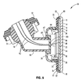
- FIG. 6 is an enlarged cross-sectional view of FIG. 1 ;
- FIG. 7 is an enlarged cross-sectional view of a rearview device with enlarged peripheral walls.
- the terms “upper,” “lower,” “right,” “left,” “rear,” “front,” “vertical,” “horizontal,” and derivatives thereof shall relate to the disclosure as oriented in FIG. 1 .
- the disclosure may assume various alternative orientations, except where expressly specified to the contrary.
- the specific devices and processes illustrated in the attached drawings, and described in the following specification are simply exemplary embodiments of the inventive concepts defined in the appended claims. Hence, specific dimensions and other physical characteristics relating to the embodiments disclosed herein are not to be considered as limiting, unless the claims expressly state otherwise.
- the term “and/or,” when used in a list of two or more items, means that any one of the listed items can be employed by itself, or any combination of two or more of the listed items can be employed.
- the composition can contain A alone; B alone; C alone; A and B in combination; A and C in combination; B and C in combination; or A, B, and C in combination.
- reference numeral 10 generally designates a rearview device having a front element 12 defining a first surface 14 and a second surface 16 .
- a rear element 18 defines a third surface 20 and a fourth surface 22 .
- An electro-optic material 24 such as an electrochromic material, is located between the front element 12 and the rear element 18 .
- a carrier plate 26 includes a front side 28 , a back side 30 , and a peripheral wall 32 .
- the front side 28 is disposed proximate the fourth surface 22 .
- a device housing 36 is operably coupled to the back side 30 of the carrier plate 26 .
- the peripheral wall 32 and an outer portion 38 of the back side 30 of the carrier plate 26 extend beyond the device housing 36 and are externally exposed.
- the rearview device 10 is generally configured for installation on a front windshield of a vehicle.
- the rearview device 10 includes a mount 50 configured for engagement with the inside surface of the windshield.
- the mount 50 includes a windshield connector 52 defining a socket 54 configured to engage a ball 56 ( FIG. 4 ) of a device support 58 .
- the ball 56 and socket 54 can be disposed inside or outside of the device housing 36 .
- the mount 50 provides for a range of movement of the rearview device 10 relative to the windshield. Further, it is also contemplated that the mount 50 can be operably coupled with the back side 30 of the carrier plate 26 inside the device housing 36 .
- the socket 54 may be similar to that set forth in U.S. Patent Application Publication No.
- the device support 58 extends into and is received by a recess 60 defined in a rear portion 62 of the device housing 36 and provides one or more of an electrical, mechanical, and data connection to the rearview device 10 .
- the height and width of the device housing 36 is considerably smaller than the height and width of the carrier plate 26 , the front element 12 , and the rear element 18 .
- the device housing 36 mounts to the back side 30 of the carrier plate 26 . More specifically, the device housing 36 mounts to a fastening arrangement in the form of an engagement wall 66 extending from the back side 30 of the carrier plate 26 .
- the rearwardly extending engagement wall 66 of the carrier plate 26 is configured for mechanical attachment with the device housing 36 .
- the device housing 36 is generally configured to house, support, and protect electrical components, including at least one circuit board.
- the device housing 36 is slightly tapered and configured for engagement with the engagement wall 66 disposed on the back side 30 of the carrier plate 26 . It is generally contemplated that the engagement wall 66 may engage an inside of the device housing 36 or an outside of the device housing 36 during assembly. It is also contemplated that the carrier plate 26 could be integrally formed or molded with the device housing 36 as a single piece.
- the front element 12 is exposed while the rear element 18 is positioned behind the front element 12 .
- the front element 12 has a greater height and width than the rear element 18 and also includes a rounded front edge 70 .
- the rounded front edge 70 provides a smooth and aesthetically pleasing look to the rearview device 10 .
- the carrier plate 26 includes a rounded rear transition portion 72 similar to the rounded front edge 70 of the front element 12 .
- the carrier plate 26 wraps around the rear element 18 and abuts the second surface 16 of the front element 12 . This construction provides a uniform and smooth transition from the carrier plate 26 to the front element 12 and encloses the rear element 18 and also conceals the rear element 18 from view.
- the carrier plate 26 can abut the fourth surface 22 of the rear element 18 .
- a periphery of the rear element 18 may be exposed.
- a seal 80 may be disposed between the carrier plate 26 and the front element 12 that maintains the front element 12 and the carrier plate 26 coupled.
- a knurled or otherwise rough surface may be formed on the peripheral wall 32 that assists a user in grasping the rearview device 10 and adjusting the same prior to or during travel.
- the rounded front edge 70 of the front element 12 may be smooth, frosted, etc. to complement the feel and appearance of the carrier plate 26 .
- the present disclosure may be used with a rearview assembly such as that described in U.S. Pat. Nos. 8,925,891; 8,814,373; 8,201,800; and 8,210,695; U.S. Patent Application Publication Nos. 2014/0063630 and 2012/0327234; and U.S. Provisional Patent Application Nos. 61/709,716; 61/707,676; and 61/704,869, which are hereby incorporated herein by reference in their entirety. Further, the present disclosure may be used with a rearview packaging assembly such as that described in U.S. Pat. Nos. 8,885,240; 8,814,373; 8,646,924; 8,643,931; and 8,264,761; and U.S.
- the term “coupled” in all of its forms, couple, coupling, coupled, etc. generally means the joining of two components (electrical or mechanical) directly or indirectly to one another. Such joining may be stationary in nature or movable in nature. Such joining may be achieved with the two components (electrical or mechanical) and any additional intermediate members being integrally formed as a single unitary body with one another or with the two components. Such joining may be permanent in nature or may be removable or releasable in nature unless otherwise stated.
Landscapes
- Physics & Mathematics (AREA)
- Engineering & Computer Science (AREA)
- Nonlinear Science (AREA)
- Multimedia (AREA)
- Mechanical Engineering (AREA)
- Optics & Photonics (AREA)
- General Physics & Mathematics (AREA)
- Chemical & Material Sciences (AREA)
- Crystallography & Structural Chemistry (AREA)
- Rear-View Mirror Devices That Are Mounted On The Exterior Of The Vehicle (AREA)
- Casings For Electric Apparatus (AREA)
- Fittings On The Vehicle Exterior For Carrying Loads, And Devices For Holding Or Mounting Articles (AREA)
- Electrochromic Elements, Electrophoresis, Or Variable Reflection Or Absorption Elements (AREA)
Priority Applications (1)
| Application Number | Priority Date | Filing Date | Title |
|---|---|---|---|
| US14/707,148 US9545882B2 (en) | 2014-05-08 | 2015-05-08 | Rearview device with exposed carrier plate |
Applications Claiming Priority (2)
| Application Number | Priority Date | Filing Date | Title |
|---|---|---|---|
| US201461990480P | 2014-05-08 | 2014-05-08 | |
| US14/707,148 US9545882B2 (en) | 2014-05-08 | 2015-05-08 | Rearview device with exposed carrier plate |
Publications (2)
| Publication Number | Publication Date |
|---|---|
| US20150321611A1 US20150321611A1 (en) | 2015-11-12 |
| US9545882B2 true US9545882B2 (en) | 2017-01-17 |
Family
ID=54367095
Family Applications (1)
| Application Number | Title | Priority Date | Filing Date |
|---|---|---|---|
| US14/707,148 Active US9545882B2 (en) | 2014-05-08 | 2015-05-08 | Rearview device with exposed carrier plate |
Country Status (6)
| Country | Link |
|---|---|
| US (1) | US9545882B2 (https=) |
| EP (1) | EP3140160B1 (https=) |
| JP (2) | JP2017515747A (https=) |
| KR (1) | KR101729000B1 (https=) |
| CN (1) | CN106458095A (https=) |
| WO (1) | WO2015172032A1 (https=) |
Cited By (3)
| Publication number | Priority date | Publication date | Assignee | Title |
|---|---|---|---|---|
| US20170313251A1 (en) * | 2013-04-22 | 2017-11-02 | Magna Mirrors Of America, Inc. | Rearview mirror assembly for vehicle |
| US10632921B2 (en) * | 2009-04-23 | 2020-04-28 | Magna Mirrors Of America, Inc. | Interior rearview mirror assembly for a vehicle |
| US12005839B2 (en) | 2009-04-23 | 2024-06-11 | Magna Mirrors Of America, Inc. | Vehicular interior rearview mirror assembly |
Families Citing this family (7)
| Publication number | Priority date | Publication date | Assignee | Title |
|---|---|---|---|---|
| US11046251B2 (en) | 2014-09-19 | 2021-06-29 | Magna Mirrors Of America, Inc. | Interior rearview mirror with GDO module |
| JP6807391B2 (ja) * | 2015-12-04 | 2021-01-06 | ジェンテックス コーポレイション | ベゼルとガラスが緊密に嵌合したミラーアセンブリ |
| US10850667B2 (en) * | 2017-05-04 | 2020-12-01 | Magna Mirrors Of America | Interior rearview mirror assembly |
| CN115135534A (zh) * | 2020-02-11 | 2022-09-30 | 金泰克斯公司 | 后视装置 |
| US11485289B2 (en) * | 2020-04-08 | 2022-11-01 | Magna Mirrors Of America, Inc. | Vehicular rearview mirror assembly |
| USD1001700S1 (en) * | 2021-12-30 | 2023-10-17 | Gentex Corporation | Rearview mirror for a vehicle |
| JP2025540321A (ja) * | 2022-12-09 | 2025-12-11 | ジェンテックス コーポレイション | ミラー要素の基体に固定されたマウントを備える薄型ミラー |
Citations (6)
| Publication number | Priority date | Publication date | Assignee | Title |
|---|---|---|---|---|
| US5649756A (en) * | 1991-09-13 | 1997-07-22 | Donnelly Corporation | Rearview mirror with lighting assembly |
| EP1024051A2 (de) | 1999-01-28 | 2000-08-02 | MEKRA Lang GmbH & Co. KG | Rückspiegel für Kraftfahrzeuge |
| US20100033857A1 (en) | 2008-08-06 | 2010-02-11 | Filipiak Kenneth R | Two ball mount with wiring passage |
| US8638488B2 (en) | 2002-09-30 | 2014-01-28 | Gentex Corporation | Vehicular rearview mirror elements and assemblies incorporating these elements |
| US8730553B2 (en) * | 2009-04-23 | 2014-05-20 | Magna Mirrors Of America, Inc. | Frameless interior rearview mirror assembly |
| US9174578B2 (en) * | 2013-04-22 | 2015-11-03 | Magna Mirrors Of America, Inc. | Interior rearview mirror assembly |
Family Cites Families (19)
| Publication number | Priority date | Publication date | Assignee | Title |
|---|---|---|---|---|
| US3198070A (en) * | 1961-12-01 | 1965-08-03 | Chrysler Corp | Rear view mirror containing a fluid light controlling medium |
| JPS5124029Y2 (https=) * | 1973-02-23 | 1976-06-19 | ||
| JPS5730639A (en) * | 1980-07-31 | 1982-02-18 | Ichikoh Ind Ltd | Anti-glare mirror device |
| JPH0467543U (https=) * | 1990-10-19 | 1992-06-16 | ||
| JPH04123844U (ja) * | 1991-04-25 | 1992-11-10 | 市光工業株式会社 | インサイドミラー |
| JP3286553B2 (ja) * | 1997-03-17 | 2002-05-27 | 株式会社村上開明堂 | 防眩インナーミラー |
| KR200200813Y1 (ko) * | 2000-05-19 | 2000-10-16 | 김우재 | 자동차용 실내 후사경 |
| US6467919B1 (en) * | 2001-11-02 | 2002-10-22 | Gentex Corporation | Mirror with split ball mount and hold-open device |
| US7121028B2 (en) * | 2002-12-09 | 2006-10-17 | U-Haul International, Inc. | Method and apparatus for converting a rearview mirror into a dedicated information display |
| US7221363B2 (en) * | 2003-02-12 | 2007-05-22 | Gentex Corporation | Vehicle information displays |
| JP4979376B2 (ja) * | 2003-05-06 | 2012-07-18 | ジェンテックス コーポレイション | 車両用バックミラー要素及びこれらの要素を組み込むアセンブリ |
| US20050128610A1 (en) * | 2003-11-03 | 2005-06-16 | Parker Brian R. | Rearview mirror assembly including a housing having a wiring cover |
| FR2874100B1 (fr) * | 2004-08-04 | 2006-09-29 | Saint Gobain | Systeme electrochimique comportant au moins une zone de margeage partiel |
| JP2006103623A (ja) * | 2004-10-08 | 2006-04-20 | Ichikoh Ind Ltd | 防眩タイプの車両用インサイドミラー装置 |
| JP2006103620A (ja) * | 2004-10-08 | 2006-04-20 | Ichikoh Ind Ltd | 車両用ミラー装置 |
| WO2010111173A1 (en) * | 2009-03-23 | 2010-09-30 | Magna Mirrors Of America, Inc. | Interior mirror assembly with adjustable mounting assembly |
| JP5584096B2 (ja) * | 2010-11-09 | 2014-09-03 | 太平洋工業株式会社 | 車両用樹脂成形品の製造方法 |
| CN202147633U (zh) * | 2011-07-07 | 2012-02-22 | 华德塑料制品有限公司 | 嵌入式无边内后视镜 |
| CN203005254U (zh) * | 2012-10-08 | 2013-06-19 | 深圳市格比特科技有限公司 | 轻触式后视镜行驶仪 |
-
2015
- 2015-05-08 KR KR1020167031473A patent/KR101729000B1/ko active Active
- 2015-05-08 JP JP2016569054A patent/JP2017515747A/ja active Pending
- 2015-05-08 EP EP15789475.9A patent/EP3140160B1/en active Active
- 2015-05-08 US US14/707,148 patent/US9545882B2/en active Active
- 2015-05-08 WO PCT/US2015/029904 patent/WO2015172032A1/en not_active Ceased
- 2015-05-08 CN CN201580024071.8A patent/CN106458095A/zh active Pending
-
2018
- 2018-03-20 JP JP2018052750A patent/JP6657282B2/ja active Active
Patent Citations (6)
| Publication number | Priority date | Publication date | Assignee | Title |
|---|---|---|---|---|
| US5649756A (en) * | 1991-09-13 | 1997-07-22 | Donnelly Corporation | Rearview mirror with lighting assembly |
| EP1024051A2 (de) | 1999-01-28 | 2000-08-02 | MEKRA Lang GmbH & Co. KG | Rückspiegel für Kraftfahrzeuge |
| US8638488B2 (en) | 2002-09-30 | 2014-01-28 | Gentex Corporation | Vehicular rearview mirror elements and assemblies incorporating these elements |
| US20100033857A1 (en) | 2008-08-06 | 2010-02-11 | Filipiak Kenneth R | Two ball mount with wiring passage |
| US8730553B2 (en) * | 2009-04-23 | 2014-05-20 | Magna Mirrors Of America, Inc. | Frameless interior rearview mirror assembly |
| US9174578B2 (en) * | 2013-04-22 | 2015-11-03 | Magna Mirrors Of America, Inc. | Interior rearview mirror assembly |
Non-Patent Citations (1)
| Title |
|---|
| International Searching Authority, International Search Report and Written Opinion for International Application No. PCT/US2015/029904, Jul. 16, 2015, 8 pages. |
Cited By (8)
| Publication number | Priority date | Publication date | Assignee | Title |
|---|---|---|---|---|
| US10632921B2 (en) * | 2009-04-23 | 2020-04-28 | Magna Mirrors Of America, Inc. | Interior rearview mirror assembly for a vehicle |
| US11472340B2 (en) | 2009-04-23 | 2022-10-18 | Magna Mirrors Of America, Inc. | Method of making a mirror substrate for a vehicular rearview mirror assembly |
| US12005839B2 (en) | 2009-04-23 | 2024-06-11 | Magna Mirrors Of America, Inc. | Vehicular interior rearview mirror assembly |
| US20170313251A1 (en) * | 2013-04-22 | 2017-11-02 | Magna Mirrors Of America, Inc. | Rearview mirror assembly for vehicle |
| US10112538B2 (en) * | 2013-04-22 | 2018-10-30 | Magna Mirrors Of America, Inc. | Rearview mirror assembly for vehicle |
| US10589684B2 (en) | 2013-04-22 | 2020-03-17 | Magna Mirrors Of America, Inc. | Rearview mirror assembly for vehicle |
| US11479178B2 (en) | 2013-04-22 | 2022-10-25 | Magna Mirrors Of America, Inc. | Interior rearview mirror assembly for vehicle |
| US12005840B2 (en) | 2013-04-22 | 2024-06-11 | Magna Mirrors Of America, Inc. | Interior rearview mirror assembly for vehicle |
Also Published As
| Publication number | Publication date |
|---|---|
| JP6657282B2 (ja) | 2020-03-04 |
| KR20160134862A (ko) | 2016-11-23 |
| JP2018090252A (ja) | 2018-06-14 |
| CN106458095A (zh) | 2017-02-22 |
| EP3140160A1 (en) | 2017-03-15 |
| US20150321611A1 (en) | 2015-11-12 |
| JP2017515747A (ja) | 2017-06-15 |
| EP3140160A4 (en) | 2017-06-21 |
| KR101729000B1 (ko) | 2017-04-21 |
| EP3140160B1 (en) | 2019-03-13 |
| WO2015172032A1 (en) | 2015-11-12 |
Similar Documents
| Publication | Publication Date | Title |
|---|---|---|
| US9545882B2 (en) | Rearview device with exposed carrier plate | |
| US10343608B2 (en) | Rearview assembly | |
| USD921268S1 (en) | Lighting fixture | |
| USD852998S1 (en) | Rear combination lamp for an automobile | |
| USD861933S1 (en) | Rear combination lamp for automobile | |
| USD852997S1 (en) | Rear combination lamp for an automobile | |
| USD868756S1 (en) | Vehicle antenna | |
| USD851295S1 (en) | Rear combination lamp for automobile | |
| USD819850S1 (en) | Headlamp for an automobile | |
| USD826335S1 (en) | Electronic housing | |
| USD932417S1 (en) | Front panel with an integrated upper window for a vehicle canopy | |
| USD819851S1 (en) | Headlamp for an automobile | |
| USD812263S1 (en) | Rear combination lamp for an automobile | |
| USD844193S1 (en) | Rear combination lamp for an automobile | |
| USD833653S1 (en) | Headlamp for an automobile | |
| USD851294S1 (en) | Rear combination lamp for automobile | |
| USD830594S1 (en) | Rear combination lamp for an automobile | |
| USD812264S1 (en) | Rear combination lamp for an automobile | |
| USD599705S1 (en) | Automobile and/or replica thereof | |
| USD861932S1 (en) | Rear combination lamp for automobile | |
| USD937797S1 (en) | Television receiver | |
| USD852996S1 (en) | Headlamp for an automobile | |
| USD827886S1 (en) | Rear combination lamp for an automobile | |
| USD840562S1 (en) | Headlamp for an automobile | |
| USD808552S1 (en) | Headlamp for an automobile |
Legal Events
| Date | Code | Title | Description |
|---|---|---|---|
| AS | Assignment |
Owner name: GENTEX CORPORATION, MICHIGAN Free format text: ASSIGNMENT OF ASSIGNORS INTEREST;ASSIGNORS:LOCK, NIGEL T.;ROTH, MARK R.;MINIKEY, DANNY L., JR.;REEL/FRAME:035594/0262 Effective date: 20150506 |
|
| STCF | Information on status: patent grant |
Free format text: PATENTED CASE |
|
| MAFP | Maintenance fee payment |
Free format text: PAYMENT OF MAINTENANCE FEE, 4TH YEAR, LARGE ENTITY (ORIGINAL EVENT CODE: M1551); ENTITY STATUS OF PATENT OWNER: LARGE ENTITY Year of fee payment: 4 |
|
| MAFP | Maintenance fee payment |
Free format text: PAYMENT OF MAINTENANCE FEE, 8TH YEAR, LARGE ENTITY (ORIGINAL EVENT CODE: M1552); ENTITY STATUS OF PATENT OWNER: LARGE ENTITY Year of fee payment: 8 |