US9541133B2 - Rolling bearing, notably for ship's propeller or for wind turbine - Google Patents
Rolling bearing, notably for ship's propeller or for wind turbine Download PDFInfo
- Publication number
- US9541133B2 US9541133B2 US14/059,970 US201314059970A US9541133B2 US 9541133 B2 US9541133 B2 US 9541133B2 US 201314059970 A US201314059970 A US 201314059970A US 9541133 B2 US9541133 B2 US 9541133B2
- Authority
- US
- United States
- Prior art keywords
- gear
- ring
- axial
- ring gear
- rolling bearing
- Prior art date
- Legal status (The legal status is an assumption and is not a legal conclusion. Google has not performed a legal analysis and makes no representation as to the accuracy of the status listed.)
- Active, expires
Links
- 238000005096 rolling process Methods 0.000 title claims abstract description 66
- 238000005553 drilling Methods 0.000 claims description 7
- 230000002093 peripheral effect Effects 0.000 abstract description 10
- 230000000295 complement effect Effects 0.000 description 4
- 239000007787 solid Substances 0.000 description 2
- 239000000969 carrier Substances 0.000 description 1
- 230000015556 catabolic process Effects 0.000 description 1
- 238000006731 degradation reaction Methods 0.000 description 1
- 238000003754 machining Methods 0.000 description 1
- 238000004519 manufacturing process Methods 0.000 description 1
- 239000000463 material Substances 0.000 description 1
Images


Classifications
-
- F—MECHANICAL ENGINEERING; LIGHTING; HEATING; WEAPONS; BLASTING
- F16—ENGINEERING ELEMENTS AND UNITS; GENERAL MEASURES FOR PRODUCING AND MAINTAINING EFFECTIVE FUNCTIONING OF MACHINES OR INSTALLATIONS; THERMAL INSULATION IN GENERAL
- F16C—SHAFTS; FLEXIBLE SHAFTS; ELEMENTS OR CRANKSHAFT MECHANISMS; ROTARY BODIES OTHER THAN GEARING ELEMENTS; BEARINGS
- F16C33/00—Parts of bearings; Special methods for making bearings or parts thereof
- F16C33/30—Parts of ball or roller bearings
- F16C33/58—Raceways; Race rings
- F16C33/581—Raceways; Race rings integral with other parts, e.g. with housings or machine elements such as shafts or gear wheels
-
- F—MECHANICAL ENGINEERING; LIGHTING; HEATING; WEAPONS; BLASTING
- F03—MACHINES OR ENGINES FOR LIQUIDS; WIND, SPRING, OR WEIGHT MOTORS; PRODUCING MECHANICAL POWER OR A REACTIVE PROPULSIVE THRUST, NOT OTHERWISE PROVIDED FOR
- F03D—WIND MOTORS
- F03D7/00—Controlling wind motors
- F03D7/02—Controlling wind motors the wind motors having rotation axis substantially parallel to the air flow entering the rotor
- F03D7/022—Adjusting aerodynamic properties of the blades
- F03D7/0224—Adjusting blade pitch
-
- F—MECHANICAL ENGINEERING; LIGHTING; HEATING; WEAPONS; BLASTING
- F03—MACHINES OR ENGINES FOR LIQUIDS; WIND, SPRING, OR WEIGHT MOTORS; PRODUCING MECHANICAL POWER OR A REACTIVE PROPULSIVE THRUST, NOT OTHERWISE PROVIDED FOR
- F03D—WIND MOTORS
- F03D80/00—Details, components or accessories not provided for in groups F03D1/00 - F03D17/00
- F03D80/70—Bearing or lubricating arrangements
-
- F—MECHANICAL ENGINEERING; LIGHTING; HEATING; WEAPONS; BLASTING
- F16—ENGINEERING ELEMENTS AND UNITS; GENERAL MEASURES FOR PRODUCING AND MAINTAINING EFFECTIVE FUNCTIONING OF MACHINES OR INSTALLATIONS; THERMAL INSULATION IN GENERAL
- F16C—SHAFTS; FLEXIBLE SHAFTS; ELEMENTS OR CRANKSHAFT MECHANISMS; ROTARY BODIES OTHER THAN GEARING ELEMENTS; BEARINGS
- F16C33/00—Parts of bearings; Special methods for making bearings or parts thereof
- F16C33/30—Parts of ball or roller bearings
- F16C33/58—Raceways; Race rings
- F16C33/583—Details of specific parts of races
-
- F—MECHANICAL ENGINEERING; LIGHTING; HEATING; WEAPONS; BLASTING
- F16—ENGINEERING ELEMENTS AND UNITS; GENERAL MEASURES FOR PRODUCING AND MAINTAINING EFFECTIVE FUNCTIONING OF MACHINES OR INSTALLATIONS; THERMAL INSULATION IN GENERAL
- F16C—SHAFTS; FLEXIBLE SHAFTS; ELEMENTS OR CRANKSHAFT MECHANISMS; ROTARY BODIES OTHER THAN GEARING ELEMENTS; BEARINGS
- F16C41/00—Other accessories, e.g. devices integrated in the bearing not relating to the bearing function as such
-
- F—MECHANICAL ENGINEERING; LIGHTING; HEATING; WEAPONS; BLASTING
- F16—ENGINEERING ELEMENTS AND UNITS; GENERAL MEASURES FOR PRODUCING AND MAINTAINING EFFECTIVE FUNCTIONING OF MACHINES OR INSTALLATIONS; THERMAL INSULATION IN GENERAL
- F16H—GEARING
- F16H55/00—Elements with teeth or friction surfaces for conveying motion; Worms, pulleys or sheaves for gearing mechanisms
- F16H55/02—Toothed members; Worms
- F16H55/12—Toothed members; Worms with body or rim assembled out of detachable parts
-
- F—MECHANICAL ENGINEERING; LIGHTING; HEATING; WEAPONS; BLASTING
- F05—INDEXING SCHEMES RELATING TO ENGINES OR PUMPS IN VARIOUS SUBCLASSES OF CLASSES F01-F04
- F05B—INDEXING SCHEME RELATING TO WIND, SPRING, WEIGHT, INERTIA OR LIKE MOTORS, TO MACHINES OR ENGINES FOR LIQUIDS COVERED BY SUBCLASSES F03B, F03D AND F03G
- F05B2240/00—Components
- F05B2240/50—Bearings
-
- F—MECHANICAL ENGINEERING; LIGHTING; HEATING; WEAPONS; BLASTING
- F16—ENGINEERING ELEMENTS AND UNITS; GENERAL MEASURES FOR PRODUCING AND MAINTAINING EFFECTIVE FUNCTIONING OF MACHINES OR INSTALLATIONS; THERMAL INSULATION IN GENERAL
- F16C—SHAFTS; FLEXIBLE SHAFTS; ELEMENTS OR CRANKSHAFT MECHANISMS; ROTARY BODIES OTHER THAN GEARING ELEMENTS; BEARINGS
- F16C19/00—Bearings with rolling contact, for exclusively rotary movement
- F16C19/02—Bearings with rolling contact, for exclusively rotary movement with bearing balls essentially of the same size in one or more circular rows
- F16C19/04—Bearings with rolling contact, for exclusively rotary movement with bearing balls essentially of the same size in one or more circular rows for radial load mainly
- F16C19/08—Bearings with rolling contact, for exclusively rotary movement with bearing balls essentially of the same size in one or more circular rows for radial load mainly with two or more rows of balls
-
- F—MECHANICAL ENGINEERING; LIGHTING; HEATING; WEAPONS; BLASTING
- F16—ENGINEERING ELEMENTS AND UNITS; GENERAL MEASURES FOR PRODUCING AND MAINTAINING EFFECTIVE FUNCTIONING OF MACHINES OR INSTALLATIONS; THERMAL INSULATION IN GENERAL
- F16C—SHAFTS; FLEXIBLE SHAFTS; ELEMENTS OR CRANKSHAFT MECHANISMS; ROTARY BODIES OTHER THAN GEARING ELEMENTS; BEARINGS
- F16C2300/00—Application independent of particular apparatuses
- F16C2300/10—Application independent of particular apparatuses related to size
- F16C2300/14—Large applications, e.g. bearings having an inner diameter exceeding 500 mm
-
- F—MECHANICAL ENGINEERING; LIGHTING; HEATING; WEAPONS; BLASTING
- F16—ENGINEERING ELEMENTS AND UNITS; GENERAL MEASURES FOR PRODUCING AND MAINTAINING EFFECTIVE FUNCTIONING OF MACHINES OR INSTALLATIONS; THERMAL INSULATION IN GENERAL
- F16C—SHAFTS; FLEXIBLE SHAFTS; ELEMENTS OR CRANKSHAFT MECHANISMS; ROTARY BODIES OTHER THAN GEARING ELEMENTS; BEARINGS
- F16C2360/00—Engines or pumps
- F16C2360/31—Wind motors
-
- F—MECHANICAL ENGINEERING; LIGHTING; HEATING; WEAPONS; BLASTING
- F16—ENGINEERING ELEMENTS AND UNITS; GENERAL MEASURES FOR PRODUCING AND MAINTAINING EFFECTIVE FUNCTIONING OF MACHINES OR INSTALLATIONS; THERMAL INSULATION IN GENERAL
- F16H—GEARING
- F16H55/00—Elements with teeth or friction surfaces for conveying motion; Worms, pulleys or sheaves for gearing mechanisms
- F16H55/02—Toothed members; Worms
- F16H55/17—Toothed wheels
- F16H2055/175—Toothed wheels specially adapted for easy repair, e.g. exchange of worn teeth
-
- F—MECHANICAL ENGINEERING; LIGHTING; HEATING; WEAPONS; BLASTING
- F16—ENGINEERING ELEMENTS AND UNITS; GENERAL MEASURES FOR PRODUCING AND MAINTAINING EFFECTIVE FUNCTIONING OF MACHINES OR INSTALLATIONS; THERMAL INSULATION IN GENERAL
- F16H—GEARING
- F16H55/00—Elements with teeth or friction surfaces for conveying motion; Worms, pulleys or sheaves for gearing mechanisms
- F16H55/02—Toothed members; Worms
- F16H55/17—Toothed wheels
- F16H2055/176—Ring gears with inner teeth
-
- Y—GENERAL TAGGING OF NEW TECHNOLOGICAL DEVELOPMENTS; GENERAL TAGGING OF CROSS-SECTIONAL TECHNOLOGIES SPANNING OVER SEVERAL SECTIONS OF THE IPC; TECHNICAL SUBJECTS COVERED BY FORMER USPC CROSS-REFERENCE ART COLLECTIONS [XRACs] AND DIGESTS
- Y02—TECHNOLOGIES OR APPLICATIONS FOR MITIGATION OR ADAPTATION AGAINST CLIMATE CHANGE
- Y02E—REDUCTION OF GREENHOUSE GAS [GHG] EMISSIONS, RELATED TO ENERGY GENERATION, TRANSMISSION OR DISTRIBUTION
- Y02E10/00—Energy generation through renewable energy sources
- Y02E10/70—Wind energy
- Y02E10/72—Wind turbines with rotation axis in wind direction
-
- Y02E10/721—
-
- Y—GENERAL TAGGING OF NEW TECHNOLOGICAL DEVELOPMENTS; GENERAL TAGGING OF CROSS-SECTIONAL TECHNOLOGIES SPANNING OVER SEVERAL SECTIONS OF THE IPC; TECHNICAL SUBJECTS COVERED BY FORMER USPC CROSS-REFERENCE ART COLLECTIONS [XRACs] AND DIGESTS
- Y10—TECHNICAL SUBJECTS COVERED BY FORMER USPC
- Y10T—TECHNICAL SUBJECTS COVERED BY FORMER US CLASSIFICATION
- Y10T74/00—Machine element or mechanism
- Y10T74/19—Gearing
- Y10T74/1987—Rotary bodies
- Y10T74/19893—Sectional
- Y10T74/1993—Segmental rim
Definitions
- the present invention relates to the field of rolling bearings and notably relates to rolling bearings used in the field of ship's propellers or wind turbines.
- a “ship” means a high-tonnage vessel intended for maritime shipping, such as merchant shipping (oil tankers, container ships, fishing boats, etc.), warships (aircraft carriers, submarines, etc.) or alternatively large sailing boats or cruise liners.
- a ship's propeller typically takes the form of an assembly comprising an engine which drives the rotation of at least one propeller screw, this propeller being fixed to the hull of the ship, notably at the rear of the ship.
- a “pitch bearing” in order to orientate the propeller with respect to the hull of the ship.
- a wind turbine generally comprises a nacelle, mounted for rotation on a mast and enclosing a generator intended to produce electrical energy, a rotor driven by the wind and provided with a hub supporting at least two blades, and a large-sized rolling bearing supporting the rotor.
- Such a rolling bearing comprises an outer ring fixed to the hub, an inner ring fixed to one of the blades and a plurality of rolling elements, such as balls, arranged between the inner and outer rings.
- the rolling bearing comprises a ring gear provided with a peripheral inner gear teeth intended to mesh with an actuator via a gearwheel. It is known practice to form the internal gear teeth directly on the inner surface of the inner ring.
- such a rolling bearing referred to as a pitch bearing works only when it is necessary to orientate the blade or the propeller and performs small rotations, such that only a small portion of the gear teeth is used.
- a rolling bearing may be stationary for long periods of time, thus causing accelerated degradation.
- the present invention seeks to provide a rolling bearing that is easy to manufacture, to fit, is of small overall external dimensions, and allows the meshing means to be removed quickly and economically.
- the invention concerns a rolling bearing comprising an inner ring, an outer ring, at least one row of rolling elements which are arranged between raceways made on the said rings and a ring gear fixed to one of the said rings.
- the ring gear is formed of at least two independent gear segments which are each provided on their inner or outer peripheral surface with a plurality of meshing means and fixed only to one of either the inner or outer rings of the rolling bearing, the circumference of the ring gear being substantially equal to the circumference of the combination of the independent gear segments.
- the damaged gear segment can be removed without removing the other, undamaged, gear segments.
- each gear segment comprises an axial portion extending axially from a radial surface of the gear segment.
- Each of the axial portions may comprise at least one radial drilling intended to cooperate with an attachment means to one of the inner or outer rings.
- each gear segment comprises a radial portion extending radially from the axial portion in the opposite direction to the radial teeth.
- Each of the radial portions may comprise at least one axial drilling intended to cooperate with an attachment means to one of the inner or outer rings.
- the ring gear is fixed to the peripheral inner surface of the inner ring, the said independent gear segments each being provided on their inner peripheral surface with a plurality of meshing means.
- the circumference of the ring gear is less than or equal to 360°, preferably less than or equal to 120°. Indeed, when the blade is orientated, the rolling bearing makes small rotations such that only a small portion of the gear teeth is used. Use of a ring gear with a circumference of 120°or less is then sufficient and allows a significant reduction in materials.
- the ring gear is formed of four independent gear segments each extending circumferentially over substantially 90°, or of six independent gear segments each extending circumferentially over substantially 60°.
- the meshing means are radial teeth, for example designed to cooperate with a gearwheel, such as a pinion gear.
- the invention concerns a wind turbine comprising a nacelle, mounted on a mast and enclosing a generator intended to produce electrical energy, a rotor provided with a hub supporting at least two blades and a rolling bearing as described hereinabove mounted between the hub and a blade.
- the invention relates to a ship comprising a hull, a propeller enclosing an engine and propeller screws, and a rolling bearing as described hereinabove mounted between the hull and the propeller.
- FIG. 1 is a view in axial section of a rolling bearing according to a first embodiment of the invention
- FIG. 2 is a perspective view of the rolling bearing according to FIG. 1 ;
- FIG. 3 is a perspective view of the ring gear according to another embodiment
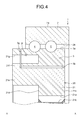
- FIG. 4 is a view in axial section of a rolling bearing according to a second embodiment of the invention.
- FIG. 5 is a perspective view of the ring gear in the rolling bearing of FIG. 4 .
- the rolling bearing of axial axis X-X, referenced 1 in FIGS. 1 to 3 , is a rolling bearing known as a pitch bearing intended to be used in a wind turbine (not depicted).
- a wind turbine comprises a nacelle placed at one end of a mast and a rotor provided with a hub supporting at least two blades which are powered by the wind in order to produce electrical energy.
- the rolling bearing 1 is designed to be placed between the hub of the rotor and one of the blades and used to orientate the blades of the wind turbine about their longitudinal axis according to the wind direction.
- the rolling bearing 1 comprises an outer ring 2 designed to be fixed to the hub (not depicted) by its cylindrical outer surface 2 a or by one of its faces, an inner ring 3 designed to be fixed to one of the blades (not depicted), two rows of rolling elements 4 , 5 , here produced in the form of balls, arranged between the inner 3 and outer 2 rings and a cage (not depicted) for maintaining the circumferential spacing between the rolling elements of each row 4 , 5 .
- a single row of rolling elements which are arranged between the inner 3 and outer 2 rings.
- solid ring is a ring the shape of which is obtained by machining with the removal of chips (turning, grinding) from tubes, bar stock, forged and/or rolled blanks.
- the outer ring 2 comprises, at its bore 2 b , two deep-groove raceways 2 c , 2 d which in cross section have a concave inner profile suited to the rolling elements 4 , 5 , the said raceways 2 c , 2 d facing radially inwards.
- the inner ring 3 also comprises, at its cylindrical outer surface 3 a , two deep-groove raceways 3 c , 3 d which in cross section have a concave internal profile suited to the rolling elements 4 , 5 , the said raceways 3 c , 3 d being directed radially outwards.
- the raceway 2 c of the outer ring 2 is aligned with the raceway 3 c of the inner ring 3 so as to accommodate the rolling elements of the first row 4 of rolling elements.
- the raceway 2 d of the outer ring 2 is aligned with the raceway 3 d of the inner ring 3 so as to accommodate the rolling elements of the second row 5 of rolling elements.
- each raceway 2 c , 2 d , 3 c , 3 d comprises two tracks for the rolling elements, these two tracks having the same radius but different centres so that each row of rolling elements adopts what is known as the “four-point contact” configuration.
- the rolling bearing 1 comprises a ring gear 6 of annular shape extending circumferentially over 360° and designed to be fixed to one of the inner or outer rings.
- a ring gear 6 of annular shape extending circumferentially over 360° and designed to be fixed to one of the inner or outer rings.
- the outer surface 6 a of the ring gear 6 is fixed to the cylindrical inner surface 3 b of the inner ring 3 .
- the inner surface 6 b of the ring gear 6 may be fixed to the cylindrical outer surface 2 a of the outer ring 2 . In that case, the inner ring 3 would be fixed to the hub and the outer ring 2 would be fixed to one of the blades.
- the ring gear 6 illustrated in detail in FIG. 2 is formed by a plurality of gear segments 7 , 8 , 9 , 10 , 11 , 12 which are independent and identical, there being for example six of these, each extending circumferentially over substantially 60°. It will be noted that a small circumferential gap is left between two adjacent gear segments.
- the gear segments may have circumferential lengths that differ from one another, while at the same time having a total circumference substantially equal to the circumference of the ring gear.
- the total circumference of the ring gear corresponds to the sum of the circumferences of each of the independent gear segments.
- the plurality of independent gear segments 7 , 8 , 9 , 10 , 11 , 12 form a ring gear with a circumference substantially equal to 360°.
- each of the independent gear segments 7 , 8 , 9 , 10 , 11 , 12 is provided on its inner peripheral surface 7 a , 8 a , 9 a , 10 a , 11 a , 12 a with a plurality of radial teeth 7 b , 8 b , 9 b , 10 b , 11 b , 12 b which are designed to mesh with a gearwheel (not depicted) of complementary shape.
- a gearwheel not depicted
- any other form of intermesh allowing the gear segments to mesh with the gearwheel could be provided.
- the independent gear segments 7 , 8 , 9 , 10 , 11 , 12 are fixed only to the inner surface 3 b of the inner ring 3 of the rolling bearing 1 and are not fixed to one another.
- Each gear segment 7 , 8 , 9 , 10 , 11 , 12 comprises two lateral radial surfaces 7 c , 7 d , 8 c , 8 d , 9 c , 9 d , 10 c , 10 d , 11 c , 12 d .
- segments 8 , 9 , 10 , 11 and 12 are identical to segment 7 .
- the gear segment 7 comprises an axial portion 7 e (referred to as the first axial section in the claims) extending axially from the second lateral radial surface 7 d of the gear segment 7 , opposite to the first lateral surface 7 c .
- the outside diameter of the axial portion 7 e is substantially identical to the outside diameter of the gear segment 7 and the inside diameter of the axial portion 7 e is greater than the diameter of the interior surface 7 a of the gear segment 7 .
- the axial portion 7 e comprises a plurality of radial drillings 7 f each one designed to cooperate with an attachment means (not depicted) cooperating with a corresponding radial drilling 3 e made in the inner surface 3 b of the inner ring 3 .
- the attachment means may, for example, be a screw-fastener means, such as screw-nut systems, or rivets.
- FIG. 3 differs from the embodiment illustrated in FIGS. 1 and 2 in terms of the number of gear segments.
- the ring gear 6 is formed of four gear segments 15 , 16 , 17 , 18 which are identical and independent from one another, each extending circumferentially over substantially 90°.
- Each of the gear segments 15 , 16 , 17 , 18 is provided on its inner peripheral surface 15 a , 16 a , 17 a , 18 a with a plurality of radial teeth 15 b , 16 b , 17 b , 18 b intended to mesh with a gearwheel (not depicted) of complementary shape.
- a gearwheel not depicted
- any other form of intermesh that allows the gear segments to mesh with the gearwheel could be provided.
- the independent gear segments 15 , 16 , 17 , 18 are fixed only to the inner ring 3 of the rolling bearing 1 and are not fixed to one another.
- FIGS. 4 and 5 differs from the embodiment illustrated in FIGS. 1 to 2 in terms of the shape of the gear segments.
- gear segments greater than or equal to two may be provided.
- the gear segments may have different circumferential lengths, while at the same time forming a ring gear of substantially 360°.
- each of the independent gear segments 21 , 22 , 23 , 24 is provided on its inner peripheral surface 21 a , 22 a , 23 a , 24 a with a plurality of radial teeth 21 b , 22 b , 23 b , 24 b designed to mesh with a gearwheel (not depicted) of complementary shape.
- a gearwheel not depicted
- Each gear segment 21 , 22 , 23 , 24 comprises two lateral radial surfaces 21 c , 21 d , 22 c , 22 d , 23 c , 23 d , 24 c , 24 d.
- Each gear segment 21 , 22 , 23 , 24 comprises an axial portion 21 e , 22 e , 23 e , 24 e extending axially from the second lateral radial surface 21 d , 22 d , 23 d , 24 d of the gear segment 21 , 22 , 23 , 24 , opposite to the first lateral surface 21 c , 22 c , 23 c , 24 c .
- the outside diameter of the axial portion 21 e , 22 e , 23 e , 24 e is substantially identical to the outside diameter of the corresponding gear segment 21 , 22 , 23 , 24 , and the inside diameter of the axial portion 21 e , 22 e , 23 e , 24 e is greater than the diameter of the inner surface 21 a , 22 a , 23 a , 24 a of the corresponding gear segment 21 , 22 , 23 , 24 .
- each gear portion 21 , 22 , 23 , 24 comprises a radial portion 21 f , 22 f , 23 f , 24 f extending radially from the axial portion 21 e , 22 e , 23 e , 24 e in the opposite direction to the radial teeth 21 b , 22 b , 23 b , 24 b towards the outer ring 2 .
- Each radial portion 21 f , 22 f , 23 f , 24 f comprises a plurality of axial drillings 21 g , 22 g , 23 g , 24 g each designed to cooperate with an attachment means (not depicted) cooperating with a corresponding axial drilling 3 f made in a lateral radial surface 3 g of the inner ring 3 .
- the special structure of the gear segments allows for ease of attachment to the inner ring, either radially or axially.
- a ship generally comprises a propeller comprising an engine and at least one propeller screw for propelling the ship.
- the propeller is mounted on the hull of the ship, notably at the rear of the ship, via the rolling bearing 1 .
- the rolling bearing 1 allows the propeller to be orientated with respect to the hull of the ship in order to steer the ship.
Abstract
Rolling bearing (1) comprising an inner ring (3), an outer ring (2), at least one row of rolling elements which are arranged between raceways made on the rings (2, 3) and an ring gear (6) fixed to one of the rings (2). The ring gear (6) is formed of at least two independent gear segments (7, 8, 9, 10, 11, 12) which are each provided on their inner or outer peripheral surface with a plurality of meshing means (7 b, 8 b, 9 b, 10 b, 11 b , 12 b) and fixed only to one of either the inner or outer rings (3) of the rolling bearing (1), the circumference of the ring gear (6, 20) being substantially equal to the circumference of the combination of the independent gear segments.
Description
This application claims priority to French Patent Application No. FR1260016 filed on Oct. 22, 2012, the contents of which is fully incorporated herein by reference.
The present invention relates to the field of rolling bearings and notably relates to rolling bearings used in the field of ship's propellers or wind turbines.
A “ship” means a high-tonnage vessel intended for maritime shipping, such as merchant shipping (oil tankers, container ships, fishing boats, etc.), warships (aircraft carriers, submarines, etc.) or alternatively large sailing boats or cruise liners. A ship's propeller typically takes the form of an assembly comprising an engine which drives the rotation of at least one propeller screw, this propeller being fixed to the hull of the ship, notably at the rear of the ship. In order to steer the ship, it is known practice to use what is known as a “pitch bearing” in order to orientate the propeller with respect to the hull of the ship.
A wind turbine generally comprises a nacelle, mounted for rotation on a mast and enclosing a generator intended to produce electrical energy, a rotor driven by the wind and provided with a hub supporting at least two blades, and a large-sized rolling bearing supporting the rotor.
In order to control the load supplied to the rotor, it is common to use a pitch bearing in order to orientate the blades of the wind turbine about their longitudinal axis according to the wind direction.
Such a rolling bearing comprises an outer ring fixed to the hub, an inner ring fixed to one of the blades and a plurality of rolling elements, such as balls, arranged between the inner and outer rings.
The rolling bearing comprises a ring gear provided with a peripheral inner gear teeth intended to mesh with an actuator via a gearwheel. It is known practice to form the internal gear teeth directly on the inner surface of the inner ring.
However, such a rolling bearing referred to as a pitch bearing works only when it is necessary to orientate the blade or the propeller and performs small rotations, such that only a small portion of the gear teeth is used. In addition, such a rolling bearing may be stationary for long periods of time, thus causing accelerated degradation.
As the gear teeth wears, it becomes necessary to dismantle the inner ring, or even the rolling bearing in its entirety, which is a relatively complex and expensive operation.
Reference may be made to document EP 2 474 735 which describes a device for mounting a blade pitch gear on a pitch bearing of a wind turbine comprising an inner ring, an outer ring and a gear which is fixed to the inner ring by a plurality of fixing means.
Although such a device allows only the gear to be changed in the event of wear, the plurality of fixing means generates great overall external dimensions and is complicated to achieve.
Reference may also be made to document U.S. Pat. No. 7,331,761 which describes a blade pitch bearing for a wind turbine comprising an inner ring, an outer ring and two rows of rolling elements which are arranged between the rings. The inner surface of the inner ring is provided with a plurality of teeth over a portion less than 200° and intended to mesh with a gear in order to orientate the blades of the wind turbine.
However, as the gear teeth wears, it then becomes necessary to remove the inner ring in its entirety.
It is therefore an object of the present invention to remedy these disadvantages.
More specifically, the present invention seeks to provide a rolling bearing that is easy to manufacture, to fit, is of small overall external dimensions, and allows the meshing means to be removed quickly and economically.
The invention concerns a rolling bearing comprising an inner ring, an outer ring, at least one row of rolling elements which are arranged between raceways made on the said rings and a ring gear fixed to one of the said rings.
The ring gear is formed of at least two independent gear segments which are each provided on their inner or outer peripheral surface with a plurality of meshing means and fixed only to one of either the inner or outer rings of the rolling bearing, the circumference of the ring gear being substantially equal to the circumference of the combination of the independent gear segments.
Thus, the damaged gear segment can be removed without removing the other, undamaged, gear segments. Nor is there any longer any need to remove in its entirety the inner or outer ring to which the independent gear segments are fixed, or even the rolling bearing in its entirety, allowing a simplified disassembling.
Advantageously, each gear segment comprises an axial portion extending axially from a radial surface of the gear segment.
Each of the axial portions may comprise at least one radial drilling intended to cooperate with an attachment means to one of the inner or outer rings.
According to one embodiment, each gear segment comprises a radial portion extending radially from the axial portion in the opposite direction to the radial teeth.
Each of the radial portions may comprise at least one axial drilling intended to cooperate with an attachment means to one of the inner or outer rings.
According to one embodiment, the ring gear is fixed to the peripheral inner surface of the inner ring, the said independent gear segments each being provided on their inner peripheral surface with a plurality of meshing means.
According to one embodiment, the circumference of the ring gear is less than or equal to 360°, preferably less than or equal to 120°. Indeed, when the blade is orientated, the rolling bearing makes small rotations such that only a small portion of the gear teeth is used. Use of a ring gear with a circumference of 120°or less is then sufficient and allows a significant reduction in materials.
For example, the ring gear is formed of four independent gear segments each extending circumferentially over substantially 90°, or of six independent gear segments each extending circumferentially over substantially 60°.
Advantageously, the meshing means are radial teeth, for example designed to cooperate with a gearwheel, such as a pinion gear.
According to a second aspect, the invention concerns a wind turbine comprising a nacelle, mounted on a mast and enclosing a generator intended to produce electrical energy, a rotor provided with a hub supporting at least two blades and a rolling bearing as described hereinabove mounted between the hub and a blade.
According to another aspect, the invention relates to a ship comprising a hull, a propeller enclosing an engine and propeller screws, and a rolling bearing as described hereinabove mounted between the hull and the propeller.
The present invention will be better understood from reading the description of a number of embodiments which are given by way of nonlimiting examples and illustrated by the attached drawings in which:
The rolling bearing, of axial axis X-X, referenced 1 in FIGS. 1 to 3 , is a rolling bearing known as a pitch bearing intended to be used in a wind turbine (not depicted).
By way of non-limiting example, a wind turbine comprises a nacelle placed at one end of a mast and a rotor provided with a hub supporting at least two blades which are powered by the wind in order to produce electrical energy.
The rolling bearing 1 is designed to be placed between the hub of the rotor and one of the blades and used to orientate the blades of the wind turbine about their longitudinal axis according to the wind direction.
The rolling bearing 1 comprises an outer ring 2 designed to be fixed to the hub (not depicted) by its cylindrical outer surface 2 a or by one of its faces, an inner ring 3 designed to be fixed to one of the blades (not depicted), two rows of rolling elements 4, 5, here produced in the form of balls, arranged between the inner 3 and outer 2 rings and a cage (not depicted) for maintaining the circumferential spacing between the rolling elements of each row 4, 5. As an alternative, it is possible to conceive of a single row of rolling elements which are arranged between the inner 3 and outer 2 rings.
The outer 2 and inner 3 rings are solid. What is meant by “solid ring” is a ring the shape of which is obtained by machining with the removal of chips (turning, grinding) from tubes, bar stock, forged and/or rolled blanks.
The outer ring 2 comprises, at its bore 2 b, two deep- groove raceways 2 c, 2 d which in cross section have a concave inner profile suited to the rolling elements 4, 5, the said raceways 2 c, 2 d facing radially inwards. The inner ring 3 also comprises, at its cylindrical outer surface 3 a, two deep- groove raceways 3 c, 3 d which in cross section have a concave internal profile suited to the rolling elements 4, 5, the said raceways 3 c, 3 d being directed radially outwards. The raceway 2 c of the outer ring 2 is aligned with the raceway 3 c of the inner ring 3 so as to accommodate the rolling elements of the first row 4 of rolling elements. The raceway 2 d of the outer ring 2 is aligned with the raceway 3 d of the inner ring 3 so as to accommodate the rolling elements of the second row 5 of rolling elements.
In another preferred embodiment of the invention (which has not been depicted), each raceway 2 c, 2 d, 3 c, 3 d comprises two tracks for the rolling elements, these two tracks having the same radius but different centres so that each row of rolling elements adopts what is known as the “four-point contact” configuration.
The rolling bearing 1 comprises a ring gear 6 of annular shape extending circumferentially over 360° and designed to be fixed to one of the inner or outer rings. As an alternative, it is possible to conceive a ring gear that has a circumference of less than 360°, or even of 120° or less.
In the example illustrated, the outer surface 6 a of the ring gear 6 is fixed to the cylindrical inner surface 3 b of the inner ring 3. As an alternative, the inner surface 6 b of the ring gear 6 may be fixed to the cylindrical outer surface 2 a of the outer ring 2. In that case, the inner ring 3 would be fixed to the hub and the outer ring 2 would be fixed to one of the blades.
The ring gear 6 illustrated in detail in FIG. 2 is formed by a plurality of gear segments 7, 8, 9, 10, 11, 12 which are independent and identical, there being for example six of these, each extending circumferentially over substantially 60°. It will be noted that a small circumferential gap is left between two adjacent gear segments.
It will be noted that a number of segments higher than or equal to two could be provided. The gear segments may have circumferential lengths that differ from one another, while at the same time having a total circumference substantially equal to the circumference of the ring gear. The total circumference of the ring gear corresponds to the sum of the circumferences of each of the independent gear segments. By way of non-limiting example, provision could be made for the ring gear to be formed of two independent gear segments, each having a circumference of substantially 45°, so that the ring gear has a circumference of 90°.
In the example illustrated in FIG. 2 , the plurality of independent gear segments 7, 8, 9, 10, 11, 12 form a ring gear with a circumference substantially equal to 360°.
As illustrated in FIG. 2 , each of the independent gear segments 7, 8, 9, 10, 11, 12 is provided on its inner peripheral surface 7 a, 8 a, 9 a, 10 a, 11 a, 12 a with a plurality of radial teeth 7 b, 8 b, 9 b, 10 b, 11 b, 12 b which are designed to mesh with a gearwheel (not depicted) of complementary shape. As an alternative, any other form of intermesh allowing the gear segments to mesh with the gearwheel could be provided. The independent gear segments 7, 8, 9, 10, 11, 12 are fixed only to the inner surface 3 b of the inner ring 3 of the rolling bearing 1 and are not fixed to one another. As an alternative, provision could be made for the independent gear segments 7, 8, 9, 10, 11, 12 to be fixed only to the outer surface 2 a of the outer ring 2 of the rolling bearing 1.
Each gear segment 7, 8, 9, 10, 11, 12 comprises two lateral radial surfaces 7 c, 7 d, 8 c, 8 d, 9 c, 9 d, 10 c, 10 d, 11 c, 12 d.
The gear segment 7 comprises an axial portion 7 e (referred to as the first axial section in the claims) extending axially from the second lateral radial surface 7 d of the gear segment 7, opposite to the first lateral surface 7 c. The outside diameter of the axial portion 7 e is substantially identical to the outside diameter of the gear segment 7 and the inside diameter of the axial portion 7 e is greater than the diameter of the interior surface 7 a of the gear segment 7. As illustrated, the axial portion 7 e comprises a plurality of radial drillings 7 f each one designed to cooperate with an attachment means (not depicted) cooperating with a corresponding radial drilling 3 e made in the inner surface 3 b of the inner ring 3. The attachment means may, for example, be a screw-fastener means, such as screw-nut systems, or rivets.
Alternatively, these attachment means may be limited to a positioning means, such as centring pegs or a supporting shoulder.
The embodiment illustrated in FIG. 3 , in which the same elements have the same references, differs from the embodiment illustrated in FIGS. 1 and 2 in terms of the number of gear segments.
As illustrated in FIG. 3 , the ring gear 6 is formed of four gear segments 15, 16, 17, 18 which are identical and independent from one another, each extending circumferentially over substantially 90°.
Each of the gear segments 15, 16, 17, 18 is provided on its inner peripheral surface 15 a, 16 a, 17 a, 18 a with a plurality of radial teeth 15 b, 16 b, 17 b, 18 b intended to mesh with a gearwheel (not depicted) of complementary shape. As an alternative, any other form of intermesh that allows the gear segments to mesh with the gearwheel could be provided. The independent gear segments 15, 16, 17, 18 are fixed only to the inner ring 3 of the rolling bearing 1 and are not fixed to one another.
Each of the gear segments 15, 16, 17, 18 is provided on its inner peripheral surface 15 a, 16 a, 17 a, 18 a with a plurality of radial teeth 15 b, 16 b, 17 b, 18 b intended to mesh with a gearwheel (not depicted) of complementary shape. As such, the inner peripheral surface 15 a, 16 a, 17 a, 18 a is the dedendum circle of the plurality of radial teeth 15 b, 16 b, 17 b, 18 b. As an alternative, any other form of intermesh that allows the gear segments to mesh with the gearwheel could be provided. The independent gear segments 15, 16, 17, 18 are fixed only to the inner ring 3 of the rolling bearing 1 and are not fixed to one another.
The embodiment illustrated in FIGS. 4 and 5 , in which the same elements have the same references, differs from the embodiment illustrated in FIGS. 1 to 2 in terms of the shape of the gear segments.
As illustrated in FIGS. 4 and 5 , the ring gear 20, illustrated in detail in FIG. 5 , is formed of a plurality of gear segments 21, 22, 23, 24 which are identical and independent of one another, there being for example four of these, each extending circumferentially over substantially 90°. The independent gear segments 21, 22, 23, 24 are fixed only to the inner surface 3 b of the inner ring 3 of the rolling bearing 1 and are not fixed to one another.
It will be noted that a number of gear segments greater than or equal to two may be provided. As an alternative, the gear segments may have different circumferential lengths, while at the same time forming a ring gear of substantially 360°.
As illustrated in FIG. 5 , each of the independent gear segments 21, 22, 23, 24 is provided on its inner peripheral surface 21 a, 22 a, 23 a, 24 a with a plurality of radial teeth 21 b, 22 b, 23 b, 24 b designed to mesh with a gearwheel (not depicted) of complementary shape. As an alternative, it is possible to provide any other form of intermeshing that allows the gear segments to mesh with the gearwheel.
Each gear segment 21, 22, 23, 24 comprises two lateral radial surfaces 21 c, 21 d, 22 c, 22 d, 23 c, 23 d, 24 c, 24 d.
Each gear segment 21, 22, 23, 24 comprises an axial portion 21 e, 22 e, 23 e, 24 e extending axially from the second lateral radial surface 21 d, 22 d, 23 d, 24 d of the gear segment 21, 22, 23, 24, opposite to the first lateral surface 21 c, 22 c, 23 c, 24 c. The outside diameter of the axial portion 21 e, 22 e, 23 e, 24 e is substantially identical to the outside diameter of the corresponding gear segment 21, 22, 23, 24, and the inside diameter of the axial portion 21 e, 22 e, 23 e, 24 e is greater than the diameter of the inner surface 21 a, 22 a, 23 a, 24 a of the corresponding gear segment 21, 22, 23, 24. As illustrated, each gear portion 21, 22, 23, 24 comprises a radial portion 21 f, 22 f, 23 f, 24 f extending radially from the axial portion 21 e, 22 e, 23 e, 24 e in the opposite direction to the radial teeth 21 b, 22 b, 23 b, 24 b towards the outer ring 2. Each radial portion 21 f, 22 f, 23 f, 24 f comprises a plurality of axial drillings 21 g, 22 g, 23 g, 24 g each designed to cooperate with an attachment means (not depicted) cooperating with a corresponding axial drilling 3 f made in a lateral radial surface 3 g of the inner ring 3.
By virtue of the invention, as the gear teeth wears, it is easy to remove the damaged gear segment without removing the other, undamaged, gear segments and without fully removing the inner ring or even the rolling bearing in its entirety.
The special structure of the gear segments allows for ease of attachment to the inner ring, either radially or axially.
It will be noted that the rolling bearing 1 according to the invention could also be used in a high-tonnage ship (not depicted). A ship generally comprises a propeller comprising an engine and at least one propeller screw for propelling the ship. The propeller is mounted on the hull of the ship, notably at the rear of the ship, via the rolling bearing 1. As high-tonnage ships generally have no steering rudder, the rolling bearing 1 allows the propeller to be orientated with respect to the hull of the ship in order to steer the ship.
Claims (8)
1. A rolling bearing comprising:
an inner ring having a first axial end, a second axial end, and a cylindrical inner surface,
an outer ring,
at least one row of rolling elements disposed between the inner and outer rings, and
a ring gear fixed to the cylindrical inner surface of the inner ring, wherein the ring gear is formed of at least two independent gear segments, each of the at least two independent gear segments, when viewed in axial cross-section, having first and second axial sections adjacently located side-by-side so as not to radially overlap, the first axial section defining a first gear segment inner radius, the second axial section having first and second radially extending surfaces between which are located a plurality of teeth such that the plurality of teeth are located entirely on the second axial section and configured to extend radially inwardly therefrom, the plurality of teeth defining a dedendum circle forming a second gear segment inner radius, the first gear segment inner radius being greater than the second gear segment inner radius, the ring gear being completely radially overlapped by the inner ring such that, when viewed in axial cross-section, no portion of the ring gear extends axially past either of the first axial end or the second axial end of the inner ring in a direction away from the at least one row of rolling elements, a maximum outer diameter of the ring gear is equal to or less than a diameter of the cylindrical inner surface of the inner ring,
and wherein the circumference of the ring gear is substantially equal to the circumference of the combination of the at least two independent gear segments.
2. The rolling bearing according to claim 1 , wherein the first axial section further comprises at least one radial drilling designed to cooperate with an attachment means provided on the inner ring.
3. The rolling bearing according to claim 2 , wherein the circumference of the ring gear is less than or equal to 360°.
4. The rolling bearing according to claim 3 , wherein the ring gear is formed of four independent gear segments each extending circumferentially over substantially 90°.
5. The rolling bearing according to claim 3 , wherein the ring gear is formed of six independent gear segments each extending circumferentially over substantially 60°.
6. The rolling bearing according to claim 3 , wherein the circumference of the ring gear is less than or equal to 120°.
7. A wind turbine comprising:
a nacelle, mounted on a mast and enclosing a generator intended to produce electrical energy,
a rotor provided with a hub supporting at least two blades, and
a rolling bearing mounted between the hub and a blade, the rolling bearing including,
an inner ring having a first axial end, a second axial end, and a cylindrical inner surface,
an outer ring,
at least one row of rolling elements disposed between the inner and outer rings, and
a ring gear fixed to the cylindrical inner surface of the inner ring, wherein the ring gear is formed of at least two independent gear segments, each of the at least two independent gear segments, when viewed in axial cross-section, having first and second axial sections adjacently located side-by-side so as not to radially overlap, the first axial section defining a first gear segment inner radius, the second axial section having first and second radially extending surfaces between which are located a plurality of teeth such that the plurality of teeth are located entirely on the second axial section and configured to extend radially inwardly therefrom, the plurality of teeth defining a dedendum circle forming a second gear segment inner radius, the first gear segment inner radius being greater than the second gear segment inner radius, the ring gear being completely radially overlapped by the inner ring such that, when viewed in axial cross-section, no portion of the ring gear extends axially past either of the first axial end or the second axial end of the inner ring in a direction away from the at least one row of rolling elements, a maximum outer diameter of the ring gear is equal to or less than a diameter of the cylindrical inner surface of the inner ring, and wherein
the circumference of the ring gear is substantially equal to the circumference of the combination of the independent gear segments.
8. A rolling bearing comprising:
an inner ring,
an outer ring having a first axial end, a second axial end, and a cylindrical outer surface,
at least one row of rolling elements disposed between the inner and outer rings, and
a ring gear fixed to the cylindrical outer surface of the outer ring, wherein the ring gear is formed of at least two independent gear segments, each of the at least two independent gear segments, when viewed in axial cross-section, having first and second axial sections adjacently located side-by-side so as not to radially overlap, the first axial section defining a first gear segment outer radius, the second axial section having first and second radially extending surfaces between which are located a plurality of teeth such that the plurality of teeth are located entirely on the second axial section and configured to extend radially outwardly therefrom, the plurality of teeth defining a dedendum circle forming a second gear segment outer radius, the first gear segment outer radius being less than the second gear segment outer radius, the ring gear being completely radially overlapped by the outer ring such that, when viewed in axial cross-section, no portion of the ring gear extends axially past either of the first axial end or the second axial end of the outer ring in a direction away from the at least one row of rolling elements, a minimum inner diameter of the ring gear is equal to or greater than a diameter of the cylindrical outer surface of the outer ring, and
wherein the circumference of the ring gear is substantially equal to the circumference of the combination of the at least two independent gear segments.
Applications Claiming Priority (2)
| Application Number | Priority Date | Filing Date | Title |
|---|---|---|---|
| FR1260016A FR2997158B1 (en) | 2012-10-22 | 2012-10-22 | BEARING BEARING, IN PARTICULAR FOR PROPELLER OF SHIPS OR FOR WIND TURBINES |
| FR1260016 | 2012-10-22 |
Publications (2)
| Publication Number | Publication Date |
|---|---|
| US20140112789A1 US20140112789A1 (en) | 2014-04-24 |
| US9541133B2 true US9541133B2 (en) | 2017-01-10 |
Family
ID=47425132
Family Applications (1)
| Application Number | Title | Priority Date | Filing Date |
|---|---|---|---|
| US14/059,970 Active 2035-04-30 US9541133B2 (en) | 2012-10-22 | 2013-10-22 | Rolling bearing, notably for ship's propeller or for wind turbine |
Country Status (5)
| Country | Link |
|---|---|
| US (1) | US9541133B2 (en) |
| EP (1) | EP2722559A3 (en) |
| KR (1) | KR20140051087A (en) |
| CN (1) | CN103775489A (en) |
| FR (1) | FR2997158B1 (en) |
Cited By (2)
| Publication number | Priority date | Publication date | Assignee | Title |
|---|---|---|---|---|
| US20180156203A1 (en) * | 2015-07-06 | 2018-06-07 | Vestas Wind Systems A/S | Segmented pitch ring for a wind turbine blade pitch system |
| DE102018216810A1 (en) * | 2018-09-28 | 2020-04-02 | Thyssenkrupp Ag | Storage device |
Families Citing this family (8)
| Publication number | Priority date | Publication date | Assignee | Title |
|---|---|---|---|---|
| AU2015335363B2 (en) * | 2014-10-24 | 2019-02-14 | Vestas Wind Systems A/S | Repairing a gear part in a wind turbine |
| EP3135954A1 (en) * | 2015-08-25 | 2017-03-01 | Shenzhen Volmen Precision Mechanical Technology Co., Ltd | Reduction bearing and electric motor |
| FR3042238B1 (en) * | 2015-10-09 | 2017-11-24 | Ntn-Snr Roulements | LEFT LEG BEARING, OSCILLATING SYSTEM AND ROTATING SYSTEM |
| CN106122446B (en) * | 2016-08-22 | 2018-09-04 | 中国科学院上海高等研究院 | A kind of ring gear and the unit tooth for constituting the ring gear |
| CN107044487A (en) * | 2017-01-04 | 2017-08-15 | 洛阳新强联回转支承股份有限公司 | A kind of pivoting support of replaceable part tip edge |
| DK179485B1 (en) | 2017-12-04 | 2018-12-19 | Cnc Onsite Aps | Method for Repairing a Gear and Processing Machine for Carrying out the Method |
| DE102017222134A1 (en) | 2017-12-07 | 2019-06-13 | Thyssenkrupp Ag | bearing device |
| CN109869466B (en) * | 2019-03-20 | 2024-04-12 | 金华市源宝农业机械设备有限公司 | Speed change gear structure of high-speed rice transplanter |
Citations (7)
| Publication number | Priority date | Publication date | Assignee | Title |
|---|---|---|---|---|
| US3888357A (en) * | 1972-11-15 | 1975-06-10 | Caterpillar Tractor Co | Swing bearing with bolt-on segmented gear |
| US7331761B2 (en) | 2005-11-10 | 2008-02-19 | Kaydon Corporation | Wind turbine pitch bearing and method |
| US20110142631A1 (en) | 2010-08-30 | 2011-06-16 | Mitsubishi Heavy Industries, Ltd. | Wind turbine generator |
| DE102010010639A1 (en) | 2010-03-09 | 2011-09-15 | Schaeffler Technologies Gmbh & Co. Kg | Rotary connection of a rotor blade with the rotor hub of a wind turbine |
| WO2012072627A1 (en) | 2010-11-30 | 2012-06-07 | Alstom Wind, S.L.U. | Wind turbine rotor |
| EP2463521A2 (en) | 2010-12-08 | 2012-06-13 | Vestas Wind Systems A/S | Pitch gear |
| EP2474735A2 (en) | 2010-12-08 | 2012-07-11 | Vestas Wind Systems A/S | Mounting arrangement for pitch gear |
-
2012
- 2012-10-22 FR FR1260016A patent/FR2997158B1/en not_active Expired - Fee Related
-
2013
- 2013-10-11 EP EP13188335.7A patent/EP2722559A3/en not_active Withdrawn
- 2013-10-21 KR KR1020130125173A patent/KR20140051087A/en not_active Application Discontinuation
- 2013-10-22 US US14/059,970 patent/US9541133B2/en active Active
- 2013-10-22 CN CN201310753482.3A patent/CN103775489A/en active Pending
Patent Citations (10)
| Publication number | Priority date | Publication date | Assignee | Title |
|---|---|---|---|---|
| US3888357A (en) * | 1972-11-15 | 1975-06-10 | Caterpillar Tractor Co | Swing bearing with bolt-on segmented gear |
| US7331761B2 (en) | 2005-11-10 | 2008-02-19 | Kaydon Corporation | Wind turbine pitch bearing and method |
| DE102010010639A1 (en) | 2010-03-09 | 2011-09-15 | Schaeffler Technologies Gmbh & Co. Kg | Rotary connection of a rotor blade with the rotor hub of a wind turbine |
| US20130039768A1 (en) * | 2010-03-09 | 2013-02-14 | Schaeffler Technologies AG & Co. KG | Rotary connection of a rotor blade to the rotor hub of a wind energy plant |
| US20110142631A1 (en) | 2010-08-30 | 2011-06-16 | Mitsubishi Heavy Industries, Ltd. | Wind turbine generator |
| US8523521B2 (en) * | 2010-08-30 | 2013-09-03 | Mitsubishi Heavy Industries, Ltd. | Wind turbine generator |
| WO2012072627A1 (en) | 2010-11-30 | 2012-06-07 | Alstom Wind, S.L.U. | Wind turbine rotor |
| EP2463521A2 (en) | 2010-12-08 | 2012-06-13 | Vestas Wind Systems A/S | Pitch gear |
| US20120148411A1 (en) * | 2010-12-08 | 2012-06-14 | Vestas Wind Systems A/S | Pitch gear |
| EP2474735A2 (en) | 2010-12-08 | 2012-07-11 | Vestas Wind Systems A/S | Mounting arrangement for pitch gear |
Cited By (3)
| Publication number | Priority date | Publication date | Assignee | Title |
|---|---|---|---|---|
| US20180156203A1 (en) * | 2015-07-06 | 2018-06-07 | Vestas Wind Systems A/S | Segmented pitch ring for a wind turbine blade pitch system |
| US10823156B2 (en) * | 2015-07-06 | 2020-11-03 | Vestas Wind Systems A/S | Segmented pitch ring for a wind turbine blade pitch system |
| DE102018216810A1 (en) * | 2018-09-28 | 2020-04-02 | Thyssenkrupp Ag | Storage device |
Also Published As
| Publication number | Publication date |
|---|---|
| EP2722559A2 (en) | 2014-04-23 |
| EP2722559A3 (en) | 2017-09-06 |
| US20140112789A1 (en) | 2014-04-24 |
| KR20140051087A (en) | 2014-04-30 |
| FR2997158A1 (en) | 2014-04-25 |
| FR2997158B1 (en) | 2016-11-25 |
| CN103775489A (en) | 2014-05-07 |
Similar Documents
| Publication | Publication Date | Title |
|---|---|---|
| US9541133B2 (en) | Rolling bearing, notably for ship's propeller or for wind turbine | |
| US9816556B2 (en) | Rolling bearing, notably for ship's propeller or for wind turbine | |
| US8968148B2 (en) | Planetary gear reducer | |
| EP2501946B1 (en) | Double row tapered bearing assembly and wind turbine | |
| EP2679816B1 (en) | A pitch system for a wind turbine rotor | |
| CN102562454A (en) | Pitch gear | |
| WO2020000824A1 (en) | Variable pitch mechanism and wind generating set | |
| EP2772646A2 (en) | Wind turbine generator | |
| EP2707609B1 (en) | Spacer for rolling bearing, notably used in a wind turbine | |
| EP2707610B1 (en) | Spacer for rolling bearing, notably used in a wind turbine | |
| US10137980B2 (en) | Hub assembly and propeller assemblies | |
| US10274047B2 (en) | Planetary gear device with inward flange having recesses | |
| JP6208636B2 (en) | Swivel wheel bearing device for wind turbine, wind turbine rotor and wind power generator provided with the same | |
| EP3470671B1 (en) | Wind turbine pitch bearing with line contact rolling elements | |
| US20190072080A1 (en) | Shaft for a wind turbine | |
| US20190032708A1 (en) | Bearing arrangement for supporting a shaft of a gearbox | |
| JP2013076441A (en) | Turning ring bearing structure for wind turbine, and method for replacing turning ring bearing structure for wind turbine | |
| US8579754B2 (en) | Adjusting ring lock | |
| US8932002B2 (en) | Air turbine starter | |
| EP3792489A1 (en) | Bearing arrangement for a wind turbine and wind turbine | |
| EP3133307A1 (en) | Roller bearing comprising oblique contact rollers | |
| CN111492140B (en) | Wind turbine, rotor system and method for using a wind turbine | |
| KR20130002301U (en) | Ball bearing having spacer ring | |
| WO2014175746A1 (en) | Quill shaft assembly | |
| KR101205939B1 (en) | Propulsion apparatus for ship and Ship including the same |
Legal Events
| Date | Code | Title | Description |
|---|---|---|---|
| AS | Assignment |
Owner name: AKTIEBOLAGET SKF, SWEDEN Free format text: ASSIGNMENT OF ASSIGNORS INTEREST;ASSIGNORS:BOURON, CYRIL;MAGNY, JEAN-BAPTISTE;NOIROT, JEAN-BAPTISTE;AND OTHERS;SIGNING DATES FROM 20131202 TO 20131211;REEL/FRAME:031817/0794 |
|
| STCF | Information on status: patent grant |
Free format text: PATENTED CASE |
|
| MAFP | Maintenance fee payment |
Free format text: PAYMENT OF MAINTENANCE FEE, 4TH YEAR, LARGE ENTITY (ORIGINAL EVENT CODE: M1551); ENTITY STATUS OF PATENT OWNER: LARGE ENTITY Year of fee payment: 4 |