JP6208636B2 - Swivel wheel bearing device for wind turbine, wind turbine rotor and wind power generator provided with the same - Google Patents
Swivel wheel bearing device for wind turbine, wind turbine rotor and wind power generator provided with the same Download PDFInfo
- Publication number
- JP6208636B2 JP6208636B2 JP2014164017A JP2014164017A JP6208636B2 JP 6208636 B2 JP6208636 B2 JP 6208636B2 JP 2014164017 A JP2014164017 A JP 2014164017A JP 2014164017 A JP2014164017 A JP 2014164017A JP 6208636 B2 JP6208636 B2 JP 6208636B2
- Authority
- JP
- Japan
- Prior art keywords
- outer ring
- wind turbine
- ring
- rotor hub
- bearing device
- Prior art date
- Legal status (The legal status is an assumption and is not a legal conclusion. Google has not performed a legal analysis and makes no representation as to the accuracy of the status listed.)
- Expired - Fee Related
Links
Images


Classifications
-
- F—MECHANICAL ENGINEERING; LIGHTING; HEATING; WEAPONS; BLASTING
- F03—MACHINES OR ENGINES FOR LIQUIDS; WIND, SPRING, OR WEIGHT MOTORS; PRODUCING MECHANICAL POWER OR A REACTIVE PROPULSIVE THRUST, NOT OTHERWISE PROVIDED FOR
- F03D—WIND MOTORS
- F03D80/00—Details, components or accessories not provided for in groups F03D1/00 - F03D17/00
- F03D80/70—Bearing or lubricating arrangements
-
- F—MECHANICAL ENGINEERING; LIGHTING; HEATING; WEAPONS; BLASTING
- F16—ENGINEERING ELEMENTS AND UNITS; GENERAL MEASURES FOR PRODUCING AND MAINTAINING EFFECTIVE FUNCTIONING OF MACHINES OR INSTALLATIONS; THERMAL INSULATION IN GENERAL
- F16C—SHAFTS; FLEXIBLE SHAFTS; ELEMENTS OR CRANKSHAFT MECHANISMS; ROTARY BODIES OTHER THAN GEARING ELEMENTS; BEARINGS
- F16C2360/00—Engines or pumps
- F16C2360/31—Wind motors
-
- Y—GENERAL TAGGING OF NEW TECHNOLOGICAL DEVELOPMENTS; GENERAL TAGGING OF CROSS-SECTIONAL TECHNOLOGIES SPANNING OVER SEVERAL SECTIONS OF THE IPC; TECHNICAL SUBJECTS COVERED BY FORMER USPC CROSS-REFERENCE ART COLLECTIONS [XRACs] AND DIGESTS
- Y02—TECHNOLOGIES OR APPLICATIONS FOR MITIGATION OR ADAPTATION AGAINST CLIMATE CHANGE
- Y02E—REDUCTION OF GREENHOUSE GAS [GHG] EMISSIONS, RELATED TO ENERGY GENERATION, TRANSMISSION OR DISTRIBUTION
- Y02E10/00—Energy generation through renewable energy sources
- Y02E10/70—Wind energy
- Y02E10/72—Wind turbines with rotation axis in wind direction
Description
本開示は風車用旋回輪軸受装置並びにこれを備えた風車ロータ及び風力発電装置に関する。 The present disclosure relates to a slewing ring bearing device for a windmill, and a windmill rotor and a wind power generator including the same.
近年、地球環境の保全の観点から、再生エネルギーとしての風を利用して発電を行う風力発電装置の普及が進んでいる。風力発電装置は、一般に、ロータハブに取り付けられた風車翼が風を受けることによって、ロータハブ及びこれに連結された主軸が回転し、主軸の回転を増速機で増速して発電機に入力することで、発電機において電力が生成されるように構成されている。 In recent years, wind power generators that generate power using wind as a renewable energy have been widely used from the viewpoint of conservation of the global environment. Generally, in a wind turbine generator, when a wind turbine blade attached to a rotor hub receives wind, the rotor hub and a main shaft connected to the rotor hub rotate, and the rotation of the main shaft is increased by a speed increaser and input to the generator. Thus, power is generated in the generator.
風力発電装置において、風車翼のピッチ角を風速に応じた最適なピッチ角に設定するために、風車翼をロータハブに対して旋回可能に取り付けるよう構成された旋回輪軸受装置が設けられる場合がある。この旋回輪軸受装置には、内輪と外輪との間に複数の転動体(ボールベアリングやローラ等)を配設した転がり軸受が採用されている。 In a wind turbine generator, a slewing wheel bearing device configured to pivotably attach a wind turbine blade to a rotor hub may be provided in order to set the pitch angle of the wind turbine blade to an optimum pitch angle according to the wind speed. . This slewing ring bearing device employs a rolling bearing in which a plurality of rolling elements (ball bearings, rollers, etc.) are disposed between an inner ring and an outer ring.
風車翼とロータハブとに旋回輪軸受装置を介在させた風力発電装置において、風車翼やナセルに風荷重が作用する結果、軸受装置にモーメント荷重を含む不均一な荷重が加わり、内輪や外輪自体が構造変形することがある。内輪又は外輪自体に構造変形が生じると、内輪及び外輪と転動体との適切な接触状態を維持できなくなって玉荷重分布(転動体の荷重分布)が不均一となるため、軸受装置の寿命が短くなる。 In a wind turbine generator in which a slewing ring bearing device is interposed between a wind turbine blade and a rotor hub, a wind load acts on the wind turbine blade and the nacelle. Structural deformation may occur. If the inner ring or outer ring itself undergoes structural deformation, it will not be possible to maintain an appropriate contact state between the inner ring and outer ring and the rolling elements, and the ball load distribution (load distribution of the rolling elements) will become non-uniform. Shorter.
近年、発電効率向上の観点から風力発電装置の大型化が進められており、これにともなって、風車翼とロータハブとの間に設けられた旋回輪軸受装置に作用する荷重が増大傾向にある。このため、上述した内輪や外輪の構造変形を抑制する技術が検討されている。 In recent years, the size of wind power generators has been increased from the viewpoint of improving power generation efficiency, and accordingly, the load acting on the slewing ring bearing device provided between the wind turbine blades and the rotor hub tends to increase. For this reason, the technique which suppresses the structural deformation | transformation of the inner ring | wheel and outer ring | wheel mentioned above is examined.
特許文献1には、内輪と外輪の少なくとも一方の構造変形を抑制するために、内輪と外輪の少なくとも一方に軸受の軸方向に直交する側板が取り付けられた旋回輪軸受装置が開示されている。 Patent Document 1 discloses a slewing ring bearing device in which a side plate perpendicular to the axial direction of a bearing is attached to at least one of an inner ring and an outer ring in order to suppress structural deformation of at least one of an inner ring and an outer ring.
特許文献2には、外輪を補強するために、外輪の外周面にボルト穴を設けて変形抑制のための補強部材を外輪の外周面にボルトで取り付けた旋回輪軸受装置が開示されている。 Patent Document 2 discloses a slewing ring bearing device in which a bolt hole is provided on the outer peripheral surface of the outer ring and a reinforcing member for suppressing deformation is attached to the outer peripheral surface of the outer ring with a bolt in order to reinforce the outer ring.
特許文献1に記載されるように側板を用いて軸受の外輪を補強する場合、外輪の軸方向の端面に取り付けた側板の内輪側との干渉を防止する観点から、外輪の軸方向の端面に取り付けた側板と内輪との間に十分な間隙を確保する必要がある。このため、特許文献1に記載される側板を用いた補強は、内輪に適用する場合と比較して外輪に適用するのが困難である。 When reinforcing the outer ring of the bearing using the side plate as described in Patent Document 1, from the viewpoint of preventing interference with the inner ring side of the side plate attached to the axial end face of the outer ring, the axial end face of the outer ring It is necessary to secure a sufficient gap between the attached side plate and the inner ring. For this reason, the reinforcement using the side plate described in Patent Document 1 is difficult to apply to the outer ring as compared to the case of applying to the inner ring.
一方、特許文献2に記載されるように外輪の外周面にボルト穴を設けて変形抑制のための補強部材を外輪の外周面にボルトで取り付ける場合、該補強部材が内輪と干渉する恐れは無い。しかしながら、特許文献2に記載の旋回輪軸受装置では、外輪の外周面にボルトで付加的に取り付けた補強部材の剛性のみを利用して外輪の補強を行っているため、外輪の変形を抑制する効果は限定的である。また、軸受には高い剛性が要求されるが故に軸受材料には弾性率の高い材料が使用されており、また、軸受には長寿命が要求される故に軸受材料には高硬度材料が使用されており、このため、補強部材を取り付けるためのボルト穴を外輪の外周面に設ける加工を行うと、軸受の製造コストの増大を招いてしまう。 On the other hand, as described in Patent Document 2, when a bolt hole is provided on the outer peripheral surface of the outer ring and a reinforcing member for suppressing deformation is attached to the outer peripheral surface of the outer ring with a bolt, there is no possibility that the reinforcing member interferes with the inner ring. . However, in the slewing ring bearing device described in Patent Document 2, since the outer ring is reinforced using only the rigidity of the reinforcing member additionally attached to the outer peripheral surface of the outer ring with a bolt, deformation of the outer ring is suppressed. The effect is limited. In addition, because bearings require high rigidity, bearing materials use materials with high elastic modulus, and because bearings require long life, bearing materials use high hardness materials. For this reason, if the process which provides the bolt hole for attaching a reinforcement member in the outer peripheral surface of an outer ring | wheel is performed, the increase in the manufacturing cost of a bearing will be caused.
上述の事情に鑑みて、本発明の少なくとも一実施形態は、風車用旋回輪軸受装置の外輪の径方向において外側へ外輪が変形することを抑制するとともに、低コスト化を実現可能な風車用旋回輪軸受装置並びにこれを備えた風車ロータ及び風力発電装置を提供することを目的とする。 In view of the above-described circumstances, at least one embodiment of the present invention provides a windmill turning that suppresses the outer ring from being deformed outward in the radial direction of the outer ring of the windmill turning ring bearing device and can realize cost reduction. An object of the present invention is to provide a wheel bearing device, a wind turbine rotor and a wind power generator including the same.
(1)本発明の少なくとも一実施形態に係る風車用旋回輪軸受装置は、風車翼をロータハブに対して旋回可能に取り付けるための風車用旋回輪軸受装置であって、前記ロータハブに固定された外輪と、前記風車翼に固定された内輪と、前記外輪と前記内輪との間に設けられた複数の転動体と、前記外輪が前記外輪の径方向における外側へ変形しようとする際に前記外輪の外周面から伝達される力を受けるよう構成され、前記ロータハブに固定され又は前記ロータハブと一体で形成された力受け部と、を備える。 (1) A wind turbine slewing ring bearing device according to at least one embodiment of the present invention is a wind turbine slewing ring bearing device for pivotally attaching a wind turbine blade to a rotor hub, the outer ring being fixed to the rotor hub. And an inner ring fixed to the wind turbine blade, a plurality of rolling elements provided between the outer ring and the inner ring, and the outer ring when the outer ring tries to deform outward in the radial direction of the outer ring. A force receiving portion configured to receive a force transmitted from an outer peripheral surface and fixed to the rotor hub or integrally formed with the rotor hub.
上記(1)に記載の風車用旋回輪軸受装置によれば、外輪の径方向(以下、単に「径方向」と記載した場合は外輪の径方向を意味することとする)における外側へ外輪が変形しようとしたときに、ロータハブに固定され又はロータハブと一体で形成された力受け部が外輪の外周面から伝達される力を受けることにより、ロータハブの剛性を利用して径方向外側への外輪の変形を効果的に抑制することができる。これにより、複数の転動体に作用する荷重分布の乱れを抑制し、軸受の長寿命化を実現することができる。
ところで、軸受には高い剛性が要求されるが故に、軸受材料には一般に弾性率の高い材料が使用されている。また、軸受には長寿命が要求される故に軸受材料には高硬度材料が使用されている。このため、外輪を加工することは容易ではなく、外輪自体にボルト穴を設けて変形抑制のための補強部材をボルトで取り付けるような従来技術の場合には、外輪の製造コストが高くなりやすい。この点、上記(1)に記載の風車用旋回輪軸受装置によれば、外輪から伝達される力をロータハブに固定され又はロータハブと一体で形成された力受け部によって受けることで外輪の変形を抑制することができるため、変形抑制のための補強部材を取り付けるためのボルト穴等を外輪自体に設ける必要がない。このため、外輪に特段の加工を施すことなく外輪の変形を抑制することができ、軸受装置の低コスト化を実現することができる。
According to the slewing ring bearing device for wind turbines described in (1) above, the outer ring extends outward in the radial direction of the outer ring (hereinafter simply referred to as “radial direction” means the radial direction of the outer ring). When trying to deform, the force receiving portion fixed to the rotor hub or integrally formed with the rotor hub receives the force transmitted from the outer peripheral surface of the outer ring, thereby utilizing the rigidity of the rotor hub to radially outward the outer ring. Can be effectively suppressed. Thereby, the disturbance of the load distribution acting on the plurality of rolling elements can be suppressed, and the life of the bearing can be extended.
By the way, since a bearing is required to have high rigidity, a material having a high elastic modulus is generally used as a bearing material. Further, since a long life is required for the bearing, a high hardness material is used for the bearing material. For this reason, it is not easy to process the outer ring, and in the case of a conventional technique in which a bolt hole is provided in the outer ring itself and a reinforcing member for suppressing deformation is attached with a bolt, the manufacturing cost of the outer ring tends to increase. In this regard, according to the wind turbine slewing ring bearing device described in (1) above, the outer ring is deformed by receiving the force transmitted from the outer ring by a force receiving portion fixed to the rotor hub or integrally formed with the rotor hub. Since it can suppress, it is not necessary to provide the outer ring itself with a bolt hole or the like for attaching a reinforcing member for suppressing deformation. For this reason, deformation of the outer ring can be suppressed without performing special processing on the outer ring, and cost reduction of the bearing device can be realized.
(2)幾つかの実施形態では、上記(1)に記載の風車用旋回輪軸受装置において、前記力受け部は、前記外輪の外周面に対向する第1テーパ面を有し、前記第1テーパ面は、前記ロータハブに前記外輪の軸方向に沿って近づくにつれて前記外輪の外周面との間隔が小さくなるよう形成され、当該風車用旋回輪軸受装置は、前記第1テーパ面と前記外輪の外周面との間に設けられた楔部材を更に備える。 (2) In some embodiments, in the slewing wheel bearing device for wind turbines according to (1), the force receiving portion includes a first tapered surface facing an outer peripheral surface of the outer ring, and the first The tapered surface is formed so that the distance from the outer peripheral surface of the outer ring decreases as the rotor hub approaches the outer ring in the axial direction, and the wind turbine slewing ring bearing device includes the first tapered surface and the outer ring. A wedge member provided between the outer peripheral surface and the outer peripheral surface is further provided.
上記(2)に記載の風車用旋回輪軸受装置によれば、楔部材によって力受け部の第1テーパ面と外輪の外周面との隙間を無くすことができるため、外輪からの径方向外側への力を確実に力受け部に伝達することができる。このため、ロータハブの剛性を利用可能な力受部による外輪の変形抑制効果を向上させることができる。 According to the wind turbine slewing ring bearing device described in (2) above, since the gap between the first taper surface of the force receiving portion and the outer peripheral surface of the outer ring can be eliminated by the wedge member, outward from the outer ring in the radial direction. Can be reliably transmitted to the force receiving portion. For this reason, the deformation | transformation suppression effect of the outer ring | wheel by the force receiving part which can utilize the rigidity of a rotor hub can be improved.
(3)幾つかの実施形態では、上記(2)に記載の風車用旋回輪軸受装置において、前記軸方向に沿って延在し、前記楔部材を前記力受け部に固定するとともに前記楔部材に前記軸方向に沿って前記ロータハブに向かう押圧力を付与するためのボルトを更に備える。 (3) In some embodiments, in the swirl wheel bearing device for wind turbines according to (2), the wedge member extends along the axial direction, fixes the wedge member to the force receiving portion, and the wedge member. And a bolt for applying a pressing force toward the rotor hub along the axial direction.
上記(3)に記載の風車用旋回輪軸受装置によれば、軸方向に沿ってロータハブに向かう押圧力をボルトによって楔部材に付与することにより、力受け部のテーパ面と外輪の外周面とに楔部材が密着した状態を維持することができる。これにより、外輪からの径方向外側への力をより確実に力受け部に伝達することができる。このため、ロータハブの剛性を利用可能な力受部による外輪の変形抑制効果を更に向上させることができる。 According to the windmill slewing ring bearing device described in (3) above, by applying a pressing force toward the rotor hub along the axial direction to the wedge member by the bolt, the taper surface of the force receiving portion and the outer peripheral surface of the outer ring It is possible to maintain a state in which the wedge member is in close contact with each other. Thereby, the force to the radial direction outer side from an outer ring | wheel can be more reliably transmitted to a force receiving part. For this reason, the deformation suppression effect of the outer ring by the force receiving portion that can utilize the rigidity of the rotor hub can be further improved.
(4)幾つかの実施形態では、上記(1)に記載の風車用旋回輪軸受装置において、前記力受け部には、前記外輪の径方向に沿って延在するボルト穴が形成され、当該風車用旋回輪軸受装置は、先端が前記外輪の外周面に当接するように前記ボルト穴にねじ込まれたボルトを更に備える。 (4) In some embodiments, in the swirl bearing device for wind turbines according to (1) above, the force receiving portion is formed with a bolt hole extending along the radial direction of the outer ring, The slewing wheel bearing device for wind turbines further includes a bolt screwed into the bolt hole so that a tip abuts on an outer peripheral surface of the outer ring.
上記(4)に記載の風車用旋回輪軸受装置によれば、力受け部に形成されたボルト穴にねじ込まれたボルトの先端が外輪の外周面に当接しているため、外輪からの径方向外側への力を確実に力受け部に伝達することができる。このため、ロータハブの剛性を利用可能な力受部による外輪の変形抑制効果を更に向上させることができる。 According to the windmill slewing ring bearing device described in (4) above, since the tip of the bolt screwed into the bolt hole formed in the force receiving portion is in contact with the outer peripheral surface of the outer ring, the radial direction from the outer ring An outward force can be reliably transmitted to the force receiving portion. For this reason, the deformation suppression effect of the outer ring by the force receiving portion that can utilize the rigidity of the rotor hub can be further improved.
(5)幾つかの実施形態では、上記(1)に記載の風車用旋回輪軸受装置において、前記力受け部と前記外輪の外周面との隙間を塞ぐように形成された樹脂部を更に備える。 (5) In some embodiments, the slewing wheel bearing device for wind turbines according to (1) further includes a resin portion formed so as to close a gap between the force receiving portion and the outer peripheral surface of the outer ring. .
上記(5)に記載の風車用旋回輪軸受装置によれば、力受け部と外輪の外周面との隙間を樹脂部が塞いでいるため、外輪からの径方向外側への力を確実に力受け部に伝達することができる。このため、ロータハブの剛性を利用可能な力受部による外輪の変形抑制効果を更に向上させることができる。 According to the slewing wheel bearing device for a wind turbine described in (5) above, since the resin portion closes the gap between the force receiving portion and the outer peripheral surface of the outer ring, the force from the outer ring to the outer side in the radial direction is reliably increased. It can be transmitted to the receiving part. For this reason, the deformation suppression effect of the outer ring by the force receiving portion that can utilize the rigidity of the rotor hub can be further improved.
(6)幾つかの実施形態では、上記(1)に記載の風車用旋回輪軸受装置において、前記力受け部は、前記外輪の外周面に沿って延在する複数のセグメントを含むリング状ユニットであり、当該風車用旋回輪軸受装置は、前記外輪を前記外輪の径方向における外側から前記リング状ユニットによって締め付けるように前記複数のセグメント同士を締結する締結部材と、前記リング状ユニットを前記ロータハブに固定するための固定部材と、を更に備える。 (6) In some embodiments, in the slewing wheel bearing device for wind turbines according to (1) above, the force receiving portion includes a plurality of segments extending along the outer peripheral surface of the outer ring. The wind turbine slewing ring bearing device includes a fastening member that fastens the plurality of segments so that the outer ring is fastened by the ring-shaped unit from outside in a radial direction of the outer ring, and the ring-shaped unit is connected to the rotor hub. And a fixing member for fixing to.
上記(6)に記載の風車用旋回輪軸受装置によれば、固定部材によって力受け部としてのリング状ユニットがロータハブに固定されているため、ロータハブの剛性を利用可能なリング状ユニットによって外輪の変形を効果的に抑制することができる。また、締結部材による締め付け作用によってリング状ユニットの内周面が外輪の外周面と接触した状態が維持されるため、外輪からの径方向外側への力が確実にリング状ユニットに伝達される。これにより、ロータハブの剛性を利用可能なリング状ユニットによる外輪の変形抑制効果を向上させることができる。 According to the slewing ring bearing device for a wind turbine described in (6) above, since the ring-shaped unit as the force receiving portion is fixed to the rotor hub by the fixing member, the ring-shaped unit that can utilize the rigidity of the rotor hub is used. Deformation can be effectively suppressed. Further, since the state in which the inner peripheral surface of the ring-shaped unit is in contact with the outer peripheral surface of the outer ring is maintained by the tightening action of the fastening member, the radially outward force from the outer ring is reliably transmitted to the ring-shaped unit. Thereby, the deformation suppression effect of the outer ring | wheel by the ring-shaped unit which can utilize the rigidity of a rotor hub can be improved.
(7)本発明の少なくとも一実施形態に係る風車ロータは、少なくとも一つの風車翼と、前記少なくとも一つの風車翼が取り付けられたロータハブと、前記風車翼を前記ロータハブに対して旋回可能に取り付けるための風車用旋回輪軸受装置と、を備え、前記風車用旋回輪軸受装置が上記(1)乃至(6)の何れか1項に記載の風車用旋回輪軸受装置である。 (7) A wind turbine rotor according to at least one embodiment of the present invention is configured to attach at least one wind turbine blade, a rotor hub to which the at least one wind turbine blade is attached, and the wind turbine blade to be pivotable with respect to the rotor hub. The wind turbine slewing ring bearing device is the wind turbine slewing ring bearing device according to any one of (1) to (6).
上記(7)に記載の風車ロータによれば、上記(1)乃至(6)の何れか1項に記載の風車用旋回輪軸受装置によって風車翼をロータハブに取り付けているため、複数の転動体に作用する荷重分布の乱れを抑制し、軸受の長寿命化を実現することができる。これにより、軸受交換のための風車ロータの解体が必要となるリスクを低減することができる。 According to the wind turbine rotor described in (7) above, since the wind turbine blade is attached to the rotor hub by the wind turbine slewing ring bearing device described in any one of (1) to (6) above, a plurality of rolling elements It is possible to suppress the disturbance of the load distribution acting on the bearing and to extend the life of the bearing. Thereby, the risk that the disassembly of the wind turbine rotor for bearing replacement can be reduced.
(8)本発明の少なくとも一実施形態に係る風力発電装置は、上記(7)に記載の風車ロータと、前記風車ロータの回転に伴って駆動される発電機と、を備える。 (8) A wind turbine generator according to at least one embodiment of the present invention includes the windmill rotor according to (7) above and a generator driven in accordance with the rotation of the windmill rotor.
上記(8)に記載の風力発電装置によれば、上記(7)に記載の風車ロータの回転に伴って発電機が駆動されるため、軸受交換のための風車ロータの解体が必要となるリスクを低減することができ、風力発電装置の安定的な運転を実現することができる。 According to the wind turbine generator described in (8) above, since the generator is driven as the wind turbine rotor described in (7) rotates, there is a risk that the wind turbine rotor must be disassembled for bearing replacement. Can be reduced, and stable operation of the wind turbine generator can be realized.
本発明の少なくとも一実施形態によれば、風車翼をロータハブに対して旋回可能に取り付けるための風車用旋回輪軸受装置並びにこれを備えた風車ロータ及び風力発電装置において、外輪の径方向において外側へ外輪が変形することを抑制するとともに、低コスト化を実現することができる。 According to at least one embodiment of the present invention, a wind turbine slewing ring bearing device for mounting a wind turbine blade to a rotor hub so as to be pivotable, and a wind turbine rotor and a wind turbine generator having the wind turbine blades outward in the radial direction of the outer ring. While suppressing deformation of the outer ring, it is possible to reduce the cost.
以下、添付図面を参照して本発明の幾つかの実施形態について説明する。ただし、実施形態として記載されている又は図面に示されている構成部品の寸法、材質、形状、その相対的配置等は、本発明の範囲をこれに限定する趣旨ではなく、単なる説明例にすぎない。
例えば、「ある方向に」、「ある方向に沿って」、「平行」、「直交」、「中心」、「同心」或いは「同軸」「一致」等の相対的な配置関係を表す表現は、厳密にそのような相対的配置関係を表すのみならず、公差、若しくは、同じ機能が得られる程度の角度や距離をもって相対的に変位している状態も表すものとする。
また、一の構成要素を「備える」、「具える」、「具備する」、「含む」、又は、「有する」という表現は、他の構成要素の存在を除外する排他的な表現ではない。
Hereinafter, some embodiments of the present invention will be described with reference to the accompanying drawings. However, the dimensions, materials, shapes, relative arrangements, etc. of the components described in the embodiments or shown in the drawings are not intended to limit the scope of the present invention, but are merely illustrative examples. Absent.
For example, expressions expressing relative positional relationships such as “in a certain direction”, “along a certain direction”, “parallel”, “orthogonal”, “center”, “concentric”, “coaxial”, “coincidence”, etc. Not only such a relative arrangement relationship is strictly expressed, but also a state of relative displacement with a tolerance or an angle or a distance at which the same function can be obtained is also expressed.
The expression “comprising”, “comprising”, “comprising”, “including”, or “having” one constituent element is not an exclusive expression for excluding the presence of the other constituent elements.
図1は、本発明の一実施形態に係る風力発電装置100の概略構成を示す模式図ある。
風力発電装置100は、タワー2と、タワー2に支持されたナセル4と、風車ロータ6と、ナセル4に収容され風車ロータ6の回転に伴って駆動される発電機8と、を備えている。
FIG. 1 is a schematic diagram showing a schematic configuration of a
The
風車ロータ6は、少なくとも一つの風車翼10と、風車翼10が取り付けられたロータハブ12と、風車翼10をロータハブ12に対して旋回可能に取り付けるための少なくとも一つの旋回輪軸受装置14とを備えている。
The wind turbine rotor 6 includes at least one
ここで、旋回輪軸受装置14の構成例について、図2〜図11を用いて幾つかの実施形態を説明する。
Here, several embodiments of the configuration example of the slewing
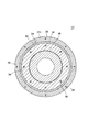
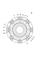
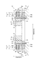
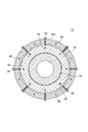
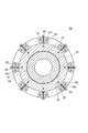
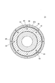
図2は、一実施形態に係る旋回輪軸受装置14の模式的な断面図である。図3は、図2に示す旋回輪軸受装置14のA−A断面の一例を示す図である。図4は、図2に示す旋回輪軸受装置14のA−A断面の一例を示す図である。図5は、一実施形態に係る旋回輪軸受装置14の模式的な断面図である。図6は、図5に示す旋回輪軸受装置14のB−B断面の一例を示す図である。図7は、図5に示す旋回輪軸受装置14のB−B断面の一例を示す図である。図8は、一実施形態に係る旋回輪軸受装置14の模式的な断面図である。図9は、図8に示す旋回輪軸受装置14のC−C断面の一例を示す図である。図10は、一実施形態に係る旋回輪軸受装置14の模式的な断面図である。図11は、図10に示す旋回輪軸受装置14のD−D断面の一例を示す図である。
FIG. 2 is a schematic cross-sectional view of the slewing
幾つかの実施形態では、例えば図2、図5、図8及び図10に示すように、旋回輪軸受装置14は、ロータハブ12に固定された外輪16と、風車翼10に固定された内輪18と、外輪16と内輪18との間に設けられた複数の転動体20と、外輪16が外輪16の径方向における外側へ変形しようとする際に外輪16の外周面16aから伝達される力を受けるよう構成され、ロータハブ12に固定された力受け部22と、を備えている。ここで、転動体20には、例えばボールやローラ等が含まれる。
In some embodiments, for example, as shown in FIGS. 2, 5, 8 and 10, the slewing
この構成によれば、外輪16の径方向(以下、単に「径方向」と記載した場合は外輪の径方向を意味することとする)における外側へ外輪16が変形しようとしたときに、ロータハブ12に固定された力受け部22が外輪16の外周面16aから伝達される力を受けることにより、ロータハブ12の剛性を利用して径方向外側への外輪16の変形を効果的に抑制することができる。これにより、複数の転動体20に作用する荷重分布の乱れを抑制し、旋回輪軸受装置14の長寿命化を実現することができる。
According to this configuration, when the
ところで、軸受には高い剛性が要求されるが故に、軸受材料には一般に弾性率の高い材料が使用される。また、軸受には長寿命が要求される故に軸受材料には高硬度材料が使用されている。このため、外輪を加工することは容易ではなく、外輪自体にボルト穴を設けて変形抑制のための補強部材をボルトで取り付けるような従来技術の場合には、外輪の製造コストが高くなりやすい。この点、図2〜図11に示した旋回輪軸受装置14によれば、外輪16から伝達される力をロータハブ12に固定された力受け部22によって受けることで外輪16の変形を抑制することができるため、変形抑制のための補強部材を取り付けるためのボルト穴等を従来技術に記載されるように外輪自体に設ける必要がない。このため、外輪16に特段の加工を施すことなく外輪16の変形を抑制することができ、旋回輪軸受装置14の低コスト化を実現することができる。
By the way, since a bearing is required to have high rigidity, a material having a high elastic modulus is generally used as a bearing material. Further, since a long life is required for the bearing, a high hardness material is used for the bearing material. For this reason, it is not easy to process the outer ring, and in the case of a conventional technique in which a bolt hole is provided in the outer ring itself and a reinforcing member for suppressing deformation is attached with a bolt, the manufacturing cost of the outer ring tends to increase. In this respect, according to the slewing
幾つかの実施形態では、例えば図2、図5、図8及び図10に示すように、力受け部22は、ロータハブ12に対してインローで組み付けられていてもよい。また、力受け部22は、例えば図2、図5及び図8に示すように、外輪の周方向全域に亘って設けられ外輪16を支持する支持部22bと、支持部22bから外輪16の外周面16aに沿って外輪16の軸方向に突出する突出部22cとを含んでいてもよい。この場合、旋回輪軸受装置14は、例えば図2及び図5に示すように、外輪16を支持部22b及びロータハブ12に共締めで固定するよう構成された複数のボルト34を備えていてもよい。あるいは、例えば図8に示すように、外輪16を支持部22bに固定するよう構成された複数のボルト35と、支持部22bをロータハブ12に固定するよう構成された複数のボルト37とを備えていてもよい。
In some embodiments, for example, as shown in FIGS. 2, 5, 8, and 10, the
幾つかの実施形態では、突出部22cは、例えば図3、図6及び図9に示すように外輪の周方向全域に亘って設けられていてもよいし、例えば図4及び図7に示すように外輪の周方向において離散的に設けられていてもよい。図4及び図7に示す例では突出部22cが外輪の周方向にそれぞれ8つ設けられている例を示したが、この数は特に限定されない。
In some embodiments, the
幾つかの実施形態では、例えば図2及び図5に示すように、支持部22bと突出部22cは別体で(別部材で)構成されており、ボルト26によって突出部22cが支持部22bに固定されていてもよい。また、他の実施形態では、例えば図8に示すように、支持部22bと突出部22cとは一体で(一つの部材で)構成されていてもよい。
In some embodiments, for example, as shown in FIGS. 2 and 5, the
幾つかの実施形態では、例えば図2に示すように、力受け部22の突出部22cは、外輪16の外周面16aに対向する第1テーパ面22aを有し、第1テーパ面22aは、ロータハブ12に外輪16の軸方向に沿って近づくにつれて外輪16の外周面16aとの間隔が小さくなるよう形成される。この場合、例えば図2に示すように、旋回輪軸受装置14は、第1テーパ面22aと外輪16の外周面16aとの間に設けられた楔部材24を備えており、楔部材24には、第1テーパ面22aに隣接する位置に第1テーパ面22aに沿って第2テーパ面24aが形成されている。
In some embodiments, for example, as shown in FIG. 2, the
なお、楔部材24は、図3に示すように外輪の周方向全域に亘って設けられていてもよいし、図4に示すように、外輪の周方向において離散的に設けられていてもよい。図4に示す例では楔部材24が外輪の周方向にそれぞれ8つ設けられている例を示したが、この数は特に限定されない。
In addition, the
この構成によれば、楔部材24によって力受け部22の第1テーパ面22aと外輪16の外周面16aとの隙間を無くすことができるため、外輪16からの径方向外側への力を楔部材24を介して確実に力受け部22に伝達することができる。このため、ロータハブ12の剛性を利用可能な力受け部22による外輪16の変形抑制効果を向上させることができる。
According to this configuration, since the gap between the
幾つかの実施形態では、例えば図2に示すように、外輪16の軸方向に沿って延在し、楔部材24を力受け部22に固定するとともに楔部材24に外輪16の軸方向に沿ってロータハブ12に向かう押圧力を付与するためのボルト26を備える。
In some embodiments, for example, as shown in FIG. 2, it extends along the axial direction of the
この構成によれば、外輪16の軸方向に沿ってロータハブ12に向かう押圧力をボルト26によって楔部材24に付与することにより、力受け部22の第1テーパ面22aと外輪16の外周面16aとに楔部材24が密着した状態を維持することができる。これにより、外輪16からの径方向外側への力を楔部材24を介してより確実に力受け部22に伝達することができる。このため、ロータハブ12の剛性を利用可能な力受け部22による外輪16の変形抑制効果を向上させることができる。
According to this configuration, by applying the pressing force toward the
なお、図2に示す例示的な実施形態では、突出部22cを支持部22bに固定するボルト26が楔部材24に押圧力を付与するボルトを兼ねている。これにより、旋回輪軸受装置14の構成を簡素化することができる。
In the exemplary embodiment shown in FIG. 2, the
また、図2に示す例示的な実施形態では、楔部材24には、ボルト26が通る通し穴29が設けられたボルト貫通部30が外輪16の径方向における第2テーパ面24aの外側に設けられている。通し穴29は所謂バカ穴であり、通し穴29の径はボルト26の軸部の径より大きく設定されている。突出部22cとボルト貫通部30との間には、ボルト26の軸方向にギャップ32が形成されている。これにより第1テーパ面22aに沿って楔部材24の位置を微調整することができる。
In the exemplary embodiment shown in FIG. 2, the
幾つかの実施形態では、例えば図5に示すように、力受け部22には、外輪16の径方向に沿って延在する少なくとも一つのボルト穴31が形成されている。この場合、例えば図5に示すように、旋回輪軸受装置14は、先端28aが外輪16の外周面16aに当接するようにボルト穴31にねじ込まれた(螺合した)少なくとも一つのボルト28を備えている。ボルト28は、図5に示すように外輪16の軸方向に複数配列されていてもよいし、図6及び図7に示すように外輪16の周方向に沿って複数配列されていてもよい。
In some embodiments, for example, as shown in FIG. 5, the
この構成によれば、力受け部22に形成されたボルト穴31にねじ込まれたボルト28の先端28aが外輪16の外周面16aに当接しているため、外輪16の径方向外側への外輪16からの力は、ボルト28とボルト穴31との螺合部を介して力受け部22に確実に伝達することができる。このため、ロータハブ12の剛性を利用可能な力受け部22による外輪16の変形抑制効果を向上させることができる。
According to this configuration, since the
なお、図5に示す実施形態では、外輪16の外周面16aと突出部22cの外周面22d(ボルト穴31の入口)との距離L1よりも大きな首下長さL2を有する少なくとも一つのボルト28を用いている。これにより、ボルト28の先端28aを外輪16の外周面16aに確実に当接させることができ、外輪16の変形抑制効果を向上させることができる。
In the embodiment shown in FIG. 5, at least one
幾つかの実施形態では、例えば図8及び図9に示すように、旋回輪軸受装置14は、力受け部22の突出部22cの内周面22eと外輪16の外周面16aとの隙間を塞ぐように形成された樹脂部36を備えている。樹脂部36は、例えば樹脂に硬化剤を添加することにより形成されてもよい。
In some embodiments, for example, as shown in FIGS. 8 and 9, the slewing
この構成によれば、力受け部22と外輪16の外周面16aとの隙間を樹脂部36が塞いでいるため、外輪16からの径方向外側への力を樹脂部36を介して確実に力受け部22に伝達することができる。このため、ロータハブ12の剛性を利用可能な力受け部22による外輪16の変形抑制効果を向上させることができる。
According to this configuration, since the
幾つかの実施形態では、例えば図8に示すように、樹脂部36が力受け部22と外輪16の外周面16aとの隙間から抜け出さないように、樹脂部36を覆う蓋部材38を備えていてもよい。この場合、蓋部材38は、例えばボルト40で突出部22cに固定されていてもよい。
In some embodiments, for example, as shown in FIG. 8, a
幾つかの実施形態では、例えば図10及び図11に示すように、力受け部22は、外輪16の外周面16aに沿って延在する複数のセグメント42aを含むリング状ユニット42である。図10及び図11に示す風車用旋回輪軸受装置14は、外輪16を外輪16の径方向における外側からリング状ユニット42によって締め付けるように複数のセグメント42a同士を締結する少なくとも一つの締結部材44(図11参照)と、リング状ユニット42をロータハブ12に固定するための少なくとも一つの固定部材46と、を備えている。
In some embodiments, for example, as shown in FIGS. 10 and 11, the
締結部材44は、例えば図10に示すように、隣接するセグメント42a同士を締結するボルト44a及びナット44bから構成されていてもよい。また、固定部材46は、例えば図10及び図11に示すようにボルトであってもよい。この場合、リング状ユニット42によって外輪16を締め付ける効果を妨げないように、セグメント42aに設けられる固定部材46の貫通穴48は、通し穴(所謂バカ穴)として形成されている。すなわち、貫通穴48の径は、固定部材46の軸部の径よりも大きく設定されている。なお、図11に示す実施形態では、外輪16はボルト50によってロータハブ12に直接固定されている。
For example, as shown in FIG. 10, the
図10及び図11に示す構成によれば、固定部材46によって力受け部22としてのリング状ユニット42がロータハブ12に固定されているため、ロータハブ12の剛性を利用可能なリング状ユニット42によって外輪16の変形を効果的に抑制することができる。また、締結部材44による締め付け作用によってリング状ユニット42の内周面42b(図10参照)が外輪16の外周面16a(図10参照)と接触した状態が維持されるため、外輪16からの径方向外側への力が確実にリング状ユニット42に伝達される。これにより、ロータハブ12の剛性を利用可能なリング状ユニット42による外輪16の変形抑制効果を向上させることができる。
10 and 11, the ring-shaped
本発明は上述した実施形態に限定されることはなく、上述した実施形態に変形を加えた形態や、これらの形態を適宜組み合わせた形態も含む。 The present invention is not limited to the above-described embodiments, and includes forms obtained by modifying the above-described embodiments and forms obtained by appropriately combining these forms.
例えば、図1〜図11に示した実施形態では、力受け部22がロータハブ12にインローで組み付けられる例を示したが、力受け部22は、ロータハブ12と一体で(一つの部材で)形成されていてもよい。
For example, in the embodiment shown in FIGS. 1 to 11, the example in which the
2 タワー
4 ナセル
6 風車ロータ
8 発電機
10 風車翼
12 ロータハブ
14 旋回輪軸受装置
16 外輪
16a 外周面
18 内輪
20 転動体
22 力受け部
22a 第1テーパ面
22b 支持部
22c 突出部
22d 外周面
22e 内周面
24 楔部材
24a 第2テーパ面
26 ボルト
28 ボルト
28a 先端
29 通し穴
30 ボルト貫通部
31 ボルト穴
32 ギャップ
34 ボルト
35 ボルト
36 樹脂部
37 ボルト
38 蓋部材
40 ボルト
42 リング状ユニット
42a セグメント
42b 内周面
44 締結部材
44a ボルト
44b ナット
46 固定部材
48 貫通穴
50 ボルト
100 風力発電装置
2 tower 4 nacelle 6 wind turbine rotor 8
Claims (4)
前記ロータハブに固定された外輪と、
前記風車翼に固定された内輪と、
前記外輪と前記内輪との間に設けられた複数の転動体と、
前記外輪が前記外輪の径方向における外側へ変形しようとする際に前記外輪の外周面から伝達される力を受けるよう構成され、前記ロータハブとは別体で形成されて前記ロータハブに固定された力受け部と、
を備え、
前記力受け部には、前記外輪の径方向に沿って延在するボルト穴が形成され、
当該風車用旋回輪軸受装置は、先端が前記外輪の外周面に当接するように前記ボルト穴にねじ込まれたボルトを更に備え、
前記力受け部は、
前記外輪の軸方向において前記外輪と前記ロータハブとの間に位置するように前記外輪の周方向全域に亘って設けられ、前記ロータハブのインロー嵌合部に嵌合されて前記ロータハブに固定される支持部と、
前記支持部から前記外輪の外周面に沿って前記軸方向に突出する突出部と、
を含む
風車用旋回輪軸受装置。 A wind turbine slewing ring bearing device for pivotally mounting a wind turbine blade to a rotor hub,
An outer ring fixed to the rotor hub;
An inner ring fixed to the wind turbine blade,
A plurality of rolling elements provided between the outer ring and the inner ring;
The outer ring is configured to receive a force transmitted from the outer peripheral surface of the outer ring when the outer ring tries to deform outward in the radial direction, and is formed separately from the rotor hub and fixed to the rotor hub . A force receiving portion;
With
The force receiving portion is formed with a bolt hole extending along the radial direction of the outer ring,
The wind turbine slewing ring bearing device further includes a bolt screwed into the bolt hole so that a tip abuts on an outer peripheral surface of the outer ring ,
The force receiving portion is
A support that is provided over the entire circumferential direction of the outer ring so as to be positioned between the outer ring and the rotor hub in the axial direction of the outer ring, and is fitted to an inlay fitting portion of the rotor hub and fixed to the rotor hub. And
A protruding portion protruding in the axial direction along the outer peripheral surface of the outer ring from the support portion;
A slewing ring bearing device for a wind turbine.
前記ロータハブに固定された外輪と、
前記風車翼に固定された内輪と、
前記外輪と前記内輪との間に設けられた複数の転動体と、
前記外輪が前記外輪の径方向における外側へ変形しようとする際に前記外輪の外周面から伝達される力を受けるよう構成され、前記ロータハブとは別体で形成されて前記ロータハブに固定された力受け部と、
前記力受け部と前記外輪の外周面との隙間を塞ぐように形成された樹脂部と、を備え、
前記力受け部は、
前記外輪の軸方向において前記外輪と前記ロータハブとの間に位置するように前記外輪の周方向全域に亘って設けられ、前記ロータハブのインロー嵌合部に嵌合されて前記ロータハブに固定される支持部と、
前記支持部から前記外輪の外周面に沿って前記軸方向に突出する突出部と、
を含む
風車用旋回輪軸受装置。 A wind turbine slewing ring bearing device for pivotally mounting a wind turbine blade to a rotor hub,
An outer ring fixed to the rotor hub;
An inner ring fixed to the wind turbine blade,
A plurality of rolling elements provided between the outer ring and the inner ring;
The outer ring is configured to receive a force transmitted from the outer peripheral surface of the outer ring when the outer ring tries to deform outward in the radial direction, and is formed separately from the rotor hub and fixed to the rotor hub . A force receiving portion;
A resin portion formed so as to close a gap between the force receiving portion and the outer peripheral surface of the outer ring ,
The force receiving portion is
A support that is provided over the entire circumferential direction of the outer ring so as to be positioned between the outer ring and the rotor hub in the axial direction of the outer ring, and is fitted to an inlay fitting portion of the rotor hub and fixed to the rotor hub. And
A protruding portion protruding in the axial direction along the outer peripheral surface of the outer ring from the support portion;
A slewing ring bearing device for a wind turbine.
前記少なくとも一つの風車翼が取り付けられたロータハブと、
前記風車翼を前記ロータハブに対して旋回可能に取り付けるための風車用旋回輪軸受装置と、
を備え、
前記風車用旋回輪軸受装置は、請求項1又は2に記載の風車用旋回輪軸受装置である、風車ロータ。 At least one windmill wing,
A rotor hub to which the at least one wind turbine blade is attached;
A wind turbine slewing ring bearing device for pivotally attaching the wind turbine blade to the rotor hub;
With
The wind turbine slewing ring bearing device according to claim 1 or 2, wherein the wind turbine slewing ring bearing device is a wind turbine rotor.
前記風車ロータの回転に伴って駆動される発電機と、
を備える風力発電装置。
A wind turbine rotor according to claim 3;
A generator driven as the wind turbine rotor rotates,
A wind power generator comprising:
Priority Applications (3)
| Application Number | Priority Date | Filing Date | Title |
|---|---|---|---|
| JP2014164017A JP6208636B2 (en) | 2014-08-12 | 2014-08-12 | Swivel wheel bearing device for wind turbine, wind turbine rotor and wind power generator provided with the same |
| EP16171889.5A EP3085957B1 (en) | 2014-08-12 | 2015-05-11 | Slewing bearing device for a wind turbine |
| EP15167123.7A EP2985458B1 (en) | 2014-08-12 | 2015-05-11 | Slewing bearing device for a wind turbine |
Applications Claiming Priority (1)
| Application Number | Priority Date | Filing Date | Title |
|---|---|---|---|
| JP2014164017A JP6208636B2 (en) | 2014-08-12 | 2014-08-12 | Swivel wheel bearing device for wind turbine, wind turbine rotor and wind power generator provided with the same |
Publications (3)
| Publication Number | Publication Date |
|---|---|
| JP2016037953A JP2016037953A (en) | 2016-03-22 |
| JP2016037953A5 JP2016037953A5 (en) | 2016-06-16 |
| JP6208636B2 true JP6208636B2 (en) | 2017-10-04 |
Family
ID=53059013
Family Applications (1)
| Application Number | Title | Priority Date | Filing Date |
|---|---|---|---|
| JP2014164017A Expired - Fee Related JP6208636B2 (en) | 2014-08-12 | 2014-08-12 | Swivel wheel bearing device for wind turbine, wind turbine rotor and wind power generator provided with the same |
Country Status (2)
| Country | Link |
|---|---|
| EP (2) | EP2985458B1 (en) |
| JP (1) | JP6208636B2 (en) |
Families Citing this family (5)
| Publication number | Priority date | Publication date | Assignee | Title |
|---|---|---|---|---|
| DK3318749T3 (en) * | 2016-11-04 | 2020-07-13 | Nordex Energy Spain Sau | WINDMILL |
| ES2723801A1 (en) * | 2018-02-26 | 2019-09-02 | Laulagun Bearings S L | Improved hub for wind turbine blade bearings (Machine-translation by Google Translate, not legally binding) |
| CN109211054B (en) * | 2018-08-13 | 2020-05-12 | 南京工大数控科技有限公司 | Detection table suitable for automatic precision assembly of ultra-large slewing bearing |
| CN110056641B (en) * | 2019-02-13 | 2022-09-23 | 株洲时代新材料科技股份有限公司 | Elastic supporting device for gear box |
| CN112283020B (en) * | 2020-10-29 | 2022-05-20 | 上海电气风电集团股份有限公司 | Wind wheel locking device and wind generating set comprising same |
Family Cites Families (10)
| Publication number | Priority date | Publication date | Assignee | Title |
|---|---|---|---|---|
| JPS55106732U (en) * | 1979-01-23 | 1980-07-25 | ||
| JPS59118823U (en) * | 1983-01-31 | 1984-08-10 | 本田技研工業株式会社 | bearing device |
| JPH0893759A (en) * | 1994-09-19 | 1996-04-09 | Koyo Seiko Co Ltd | Vibration control type rolling bearing |
| US7927019B2 (en) | 2005-05-31 | 2011-04-19 | Mitsubishi Heavy Industries Ltd. | Slewing bearing structure |
| FR2888293B1 (en) * | 2005-07-08 | 2011-01-14 | Defontaine | BEAR BEARING BEARING |
| ES2423033T5 (en) | 2007-10-01 | 2017-02-24 | Siemens Aktiengesellschaft | Step bearing for wind turbine rotor blades |
| JP2010078003A (en) * | 2008-09-24 | 2010-04-08 | Mitsubishi Heavy Ind Ltd | Speed-up device for wind-driven generator and support mechanism for rotating shaft |
| JP5495979B2 (en) * | 2010-06-28 | 2014-05-21 | 三菱重工業株式会社 | Wind power generator |
| DE102010063181A1 (en) * | 2010-12-15 | 2012-06-21 | Suzlon Energy Gmbh | Hub for a wind turbine |
| JP2013137074A (en) * | 2011-12-28 | 2013-07-11 | Mitsubishi Heavy Ind Ltd | Bearing for wind power generator and wind power generator |
-
2014
- 2014-08-12 JP JP2014164017A patent/JP6208636B2/en not_active Expired - Fee Related
-
2015
- 2015-05-11 EP EP15167123.7A patent/EP2985458B1/en active Active
- 2015-05-11 EP EP16171889.5A patent/EP3085957B1/en active Active
Also Published As
| Publication number | Publication date |
|---|---|
| EP2985458B1 (en) | 2018-03-07 |
| EP3085957B1 (en) | 2019-08-14 |
| JP2016037953A (en) | 2016-03-22 |
| EP3085957A1 (en) | 2016-10-26 |
| EP2985458A1 (en) | 2016-02-17 |
Similar Documents
| Publication | Publication Date | Title |
|---|---|---|
| JP6208636B2 (en) | Swivel wheel bearing device for wind turbine, wind turbine rotor and wind power generator provided with the same | |
| US9551324B2 (en) | Pitch bearing assembly with stiffener | |
| US9181982B2 (en) | Blade bearing with support structure having non-uniform stiffness and method manufacture | |
| US20090087127A1 (en) | Pitch bearing for wind turbine rotor blades | |
| US9175668B2 (en) | Hub for wind turbine rotor | |
| US9074581B2 (en) | Cone angle insert for wind turbine rotor | |
| CN105464897B (en) | Wind turbine rotor shaft arrangement | |
| US20150063736A1 (en) | Wind turbine bearings | |
| US9273732B2 (en) | Bearing with a supporting element and method of supporting a first ring of a bearing | |
| EP2623772A1 (en) | Wind turbine rotor | |
| US8469664B2 (en) | Yaw bearing assembly and tower for wind turbine | |
| EP2772646A2 (en) | Wind turbine generator | |
| CN109469593B (en) | Wind turbine | |
| US11725633B2 (en) | Pitch bearing for a wind turbine | |
| EP3112669B1 (en) | Pitch assembly for a wind turbine rotor blade | |
| JP2016037953A5 (en) | ||
| US20150056078A1 (en) | Pitch bearing assembly with stiffener | |
| EP2937585B1 (en) | Spacer assembly for a bearing | |
| US20190072080A1 (en) | Shaft for a wind turbine | |
| CN106438230B (en) | Reinforced main bearing for a wind turbine | |
| US11480149B2 (en) | Wind turbine, rotor system, and method for using a wind turbine | |
| KR101337622B1 (en) | Wind power generator | |
| JP2015227651A (en) | Wind power generator | |
| US10502194B2 (en) | Wind turbine bearings | |
| JP2008281121A (en) | Tapered roller bearing |
Legal Events
| Date | Code | Title | Description |
|---|---|---|---|
| A521 | Request for written amendment filed |
Free format text: JAPANESE INTERMEDIATE CODE: A523 Effective date: 20160426 |
|
| A621 | Written request for application examination |
Free format text: JAPANESE INTERMEDIATE CODE: A621 Effective date: 20160426 |
|
| A131 | Notification of reasons for refusal |
Free format text: JAPANESE INTERMEDIATE CODE: A131 Effective date: 20170331 |
|
| A977 | Report on retrieval |
Free format text: JAPANESE INTERMEDIATE CODE: A971007 Effective date: 20170330 |
|
| A521 | Request for written amendment filed |
Free format text: JAPANESE INTERMEDIATE CODE: A523 Effective date: 20170517 |
|
| TRDD | Decision of grant or rejection written | ||
| A01 | Written decision to grant a patent or to grant a registration (utility model) |
Free format text: JAPANESE INTERMEDIATE CODE: A01 Effective date: 20170901 |
|
| A61 | First payment of annual fees (during grant procedure) |
Free format text: JAPANESE INTERMEDIATE CODE: A61 Effective date: 20170907 |
|
| R150 | Certificate of patent or registration of utility model |
Ref document number: 6208636 Country of ref document: JP Free format text: JAPANESE INTERMEDIATE CODE: R150 |
|
| LAPS | Cancellation because of no payment of annual fees |