US9540208B2 - Apparatus and methods for winding coil using traverse with rotating element - Google Patents
Apparatus and methods for winding coil using traverse with rotating element Download PDFInfo
- Publication number
- US9540208B2 US9540208B2 US15/133,873 US201615133873A US9540208B2 US 9540208 B2 US9540208 B2 US 9540208B2 US 201615133873 A US201615133873 A US 201615133873A US 9540208 B2 US9540208 B2 US 9540208B2
- Authority
- US
- United States
- Prior art keywords
- wire
- mandrel
- traverse
- carriage
- terminal
- Prior art date
- Legal status (The legal status is an assumption and is not a legal conclusion. Google has not performed a legal analysis and makes no representation as to the accuracy of the status listed.)
- Active
Links
Images


Classifications
-
- B—PERFORMING OPERATIONS; TRANSPORTING
- B65—CONVEYING; PACKING; STORING; HANDLING THIN OR FILAMENTARY MATERIAL
- B65H—HANDLING THIN OR FILAMENTARY MATERIAL, e.g. SHEETS, WEBS, CABLES
- B65H54/00—Winding, coiling, or depositing filamentary material
- B65H54/02—Winding and traversing material on to reels, bobbins, tubes, or like package cores or formers
- B65H54/28—Traversing devices; Package-shaping arrangements
- B65H54/2893—Superposed traversing, i.e. traversing or other movement superposed on a traversing movement
-
- B—PERFORMING OPERATIONS; TRANSPORTING
- B65—CONVEYING; PACKING; STORING; HANDLING THIN OR FILAMENTARY MATERIAL
- B65H—HANDLING THIN OR FILAMENTARY MATERIAL, e.g. SHEETS, WEBS, CABLES
- B65H54/00—Winding, coiling, or depositing filamentary material
- B65H54/02—Winding and traversing material on to reels, bobbins, tubes, or like package cores or formers
- B65H54/28—Traversing devices; Package-shaping arrangements
- B65H54/2806—Traversing devices driven by cam
-
- B—PERFORMING OPERATIONS; TRANSPORTING
- B65—CONVEYING; PACKING; STORING; HANDLING THIN OR FILAMENTARY MATERIAL
- B65H—HANDLING THIN OR FILAMENTARY MATERIAL, e.g. SHEETS, WEBS, CABLES
- B65H54/00—Winding, coiling, or depositing filamentary material
- B65H54/02—Winding and traversing material on to reels, bobbins, tubes, or like package cores or formers
- B65H54/28—Traversing devices; Package-shaping arrangements
- B65H54/2818—Traversing devices driven by rod
-
- B—PERFORMING OPERATIONS; TRANSPORTING
- B65—CONVEYING; PACKING; STORING; HANDLING THIN OR FILAMENTARY MATERIAL
- B65H—HANDLING THIN OR FILAMENTARY MATERIAL, e.g. SHEETS, WEBS, CABLES
- B65H54/00—Winding, coiling, or depositing filamentary material
- B65H54/56—Winding of hanks or skeins
- B65H54/58—Swifts or reels adapted solely for the formation of hanks or skeins
-
- B—PERFORMING OPERATIONS; TRANSPORTING
- B65—CONVEYING; PACKING; STORING; HANDLING THIN OR FILAMENTARY MATERIAL
- B65H—HANDLING THIN OR FILAMENTARY MATERIAL, e.g. SHEETS, WEBS, CABLES
- B65H55/00—Wound packages of filamentary material
- B65H55/04—Wound packages of filamentary material characterised by method of winding
- B65H55/046—Wound packages of filamentary material characterised by method of winding packages having a radial opening through which the material will pay off
-
- B—PERFORMING OPERATIONS; TRANSPORTING
- B65—CONVEYING; PACKING; STORING; HANDLING THIN OR FILAMENTARY MATERIAL
- B65H—HANDLING THIN OR FILAMENTARY MATERIAL, e.g. SHEETS, WEBS, CABLES
- B65H2701/00—Handled material; Storage means
- B65H2701/30—Handled filamentary material
- B65H2701/36—Wires
Definitions
- This application relates to apparatus and methods for winding coils. More particularly, this application relates to apparatus and methods for winding coils of cable, wire, or filaments that can be dispensed through a payout tube. This application has particular application to the winding of coils of cable, wire, or filaments in a figure-eight pattern, although it is not limited thereto.
- U.S. Pat. No. 2,634,922 to Taylor describes the winding of flexible wire, cable or filamentary material (hereinafter “wire”, which is to be broadly understood in the specification, abstract and claims) around a mandrel in a figure-eight pattern such that a package of material is obtained having a plurality of layers surrounding a central core space.
- wire flexible wire, cable or filamentary material
- the layers of the figure-eight pattern are provided with aligned holes (cumulatively a “pay-out hole”) such that the inner end of the flexible material may be drawn out through the payout hole.
- the wire When a package of wire is wound in this manner, the wire may be unwound through the payout hole without rotating the package, without imparting a rotation in the wire around its axis (i.e., twisting), and without kinking.
- This provides a major advantage to the users of the wire.
- Coils that are wound in this manner and dispense from the inside-out without twists, tangles, snags or overruns are known in the art as REELEX- (a trademark of Reelex Packaging Solutions, Inc.) type coils.
- REELEX-type coils are wound to form a generally short hollow cylinder with a radial opening formed at one location in the middle of the cylinder.
- a payout tube may be located in the radial opening and the end of the wire making up the coil may be fed through the payout tube for ease in dispensing the wire.
- U.S. Pat. No. 5,470,026 to Kotzur describes means for controlling the reciprocating movement of the traverse with respect to the rotation of the mandrel in order to wind the wire on the mandrel to form a radial payout hole having a substantially constant diameter.
- an increasing number of different types of wires with different characteristics are being wound using the systems and methods described in U.S. Pat. No. 2,635,922 and the subsequent improvements.
- the figure-eight type winding has been used for twisted-pair type cable (e.g., Category 5, Category 6 and the like), drop cable, fiber-optic cable, electrical building wire (THHN), etc.
- twisted-pair type cable e.g., Category 5, Category 6 and the like
- drop cable e.g., fiber-optic cable
- electrical building wire e.g., electrical building wire
- One embodiment of a system for winding a wire includes a spindle shaft with a mandrel thereon, and a traverse that directs the wire onto the rotating mandrel in a figure-eight pattern, where the traverse has at least one reciprocating, rotating element that reciprocates relative to the rotating mandrel and simultaneously rotates back and forth about an axis perpendicular to the axis of reciprocation.
- a tensioner also called a “dancer” or “accumulator” may be provided to control the tension on the wire as it applied to the rotating mandrel.
- a reciprocating element of the traverse is driven directly or indirectly by a crank or cam-arm and is caused to rotate by one hundred eighty degrees over the length of its movement.
- the traverse is provided with two in-line rollers and a rotating gear that is located between but offset from the rollers.
- a flexible grooved belt with fixed, optionally adjustable ends is threaded between the rollers and the rotating gear to form an open loop.
- a wire guide that reciprocates and rotates is used to lay down the wire on the spinning mandrel.
- the wire-output location (laydown point) of the wire guide is adapted to be substantially tangent to and to approximate the surface of the mandrel at a starting position and then to move radially away from the mandrel in order to approximate the surface of the coil as it is wound.
- a sensor is provided to inform movement of the traverse away from the mandrel.
- movement of the traverse away from the mandrel is controlled based on the diameter of the wire and the number of reciprocations of the traverse.
- the mandrel is barrel-shaped and end-forms are located at ends of the mandrel.
- the end-forms have flat inner surfaces, e.g., they are disk-shaped.
- the stroke of the cam-arm can be reduced, thereby permitting a faster winding.
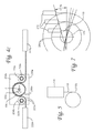
- FIG. 1 is a schematic of an embodiment of a REELEX-type winding system.
- FIG. 2 is a perspective view of the traverse and mandrel of FIG. 1 .
- FIG. 3 is a partial perspective view of the traverse and mandrel of FIG. 1 with parts removed for visualization.
- FIGS. 4 a -4 c are schematics of a rotation system for the reciprocating element of the traverse showing a carriage of the traverse in a first end position with a rotation gear in a first position, a second middle position with the rotation gear rotated into a second position, and a third end position with the rotation gear rotated into a third position.
- FIG. 5 is a schematic showing wire exiting a wire guide tangent a mandrel.
- FIG. 6 is a partial schematic of the traverse of FIG. 1 showing an adjustment mechanism.
- FIG. 7 is a schematic showing wire exiting a wire guide tangent a mandrel and tangent a coil with the wire guide moving in two axes.
- FIG. 8 a is a perspective view of another embodiment of a traverse and mandrel with parts removed for visualization, with a carriage and wire guide of the traverse in a first position.
- FIG. 8 b is a perspective view of the embodiment of the traverse and mandrel of FIG. 8 a with the carriage and wire guide in a second position.
- FIG. 9 is a front perspective view of another embodiment of a traverse.
- FIGS. 10 a -10 c are respectively a back perspective view and back views of another embodiment of a traverse.
- FIG. 1 One embodiment of a winding system 100 for winding wire 110 is seen in FIG. 1 .
- System 100 is a REELEX-type winding system and is shown with a payoff or payout unit 112 , a dancer/accumulator (tensioner) 114 , a take-up unit 116 , and a controller 118 .
- the payoff unit 112 is shown as including a large source reel 122 of wire 110 and a motor 124 that is used to control the speed at which the wire 110 is dispensed off of the reel 122 .
- the dancer/accumulator or tensioner 114 is shown with upper sheaves 142 and lower sheaves 144 around which the wire 110 wraps, a pneumatic cylinder 146 that applies pressure to the lower sheaves 144 of the tensioner 114 to effect a desired tension, and a distance or height sensor 148 (e.g., a laser or potentiometer system) that senses the location of the lower sheave 144 relative to the upper sheave 142 .
- a distance or height sensor 148 e.g., a laser or potentiometer system
- the height sensor 148 is coupled to the payoff unit 112 and can provide feedback information to the payoff unit 112 , thereby informing the payoff unit to increase its speed if the amount of wire in the accumulator is low, and informing the payoff unit to decrease its speed if the amount of wire in the accumulator is high.
- the feedback information may be provided to the take-up unit 116 and used to decrease or increase the speed thereof.
- the take-up unit 116 is shown to include a buffer 162 , a traverse 164 , a motorized spindle 166 , and a mandrel 170 .
- the traverse has a carriage that moves back and forth (reciprocates) above the surface of the mandrel 170 as the mandrel is spinning on the spindle 166 , thereby causing wire 110 to be directed onto the mandrel 170 .
- an element of the traverse that directs the wire onto the mandrel also rotates back and forth about an axis perpendicular to the reciprocation.
- the function of the entire system 100 is to cause wire 110 to be wound in a figure-eight pattern in a manner forming a payout hole extending radially out from the mandrel 170 .
- the controller 118 is coupled to the take-up system 116 and can provide speed control information to direct the take-up system 116 to run at a desired rate. For example, the controller 118 may direct the take-up system 116 to cause the spindle 166 to run at a constant speed, or may cause the take-up system 116 to have the line speed be constant, thereby requiring the spindle speed to slow down over a period of time.
- Mandrel 170 is comprised of a central hollow cylindrical element 170 a that extends around and is coupled to the spindle 166 , and a plurality of segments 170 b radially attached to the central element 170 a .
- Each segment 170 b of the mandrel is shown with an outer surface that is bowed out (convex) in two directions.
- Each segment is coupled to the central element 170 a via at least one arm or rod (not shown) which are arranged to rotate so that the segments 170 b can move from a first collapsed position (not shown) where the segments are closer to the central element 170 a and to each other, to a second expanded or extended position shown in FIG. 2 where the segments 170 b are further away from the central element 170 a and are spaced further from each other.
- the segments In the first collapsed position, the segments may touch each other or be very closely adjacent to each other.
- the segments take the shape of a bumpy barrel.
- the segments In the second expanded or extended position seen in FIGS. 2 and 3 , the segments are spaced from one another and their outer surfaces appear at any cross-section to define a circle, although again, the circle may be slightly bumpy.
- a lock may be provided to keep the segments in the expanded position and/or in the collapsed position.
- end-forms 177 may be provided that “sandwich” the mandrel segments 170 b and extend radially from the central element 170 a .
- the end-forms 177 are shaped substantially as disks. At least one of the end-forms 177 (e.g., the outer end-form) may be removed from the mandrel so that a coil of wire may be removed from the mandrel after a winding is completed.
- an end-form arm (not shown) is provided and may be activated to cause automated removal of the outer end-form 177 when the mandrel is not spinning.
- the traverse 164 is formed as a cantilevered hollow beam 164 a having a longitudinal slot 201 through which a carriage 205 extends.
- the carriage 205 is driven by a motorized cam arm 207 of the take-up unit 116 ( FIG. 1 ) which is coupled thereto and which causes the carriage 205 to reciprocate back and forth in the beam 164 a .
- the carriage 205 is coupled by a rotating tube 208 to a wire guide 210 which has one end located close to the mandrel 170 .
- Wire 110 that is to be wound on the mandrel is threaded through the carriage 205 and the tube 208 and is guided by the wire guide 210 so that it is laid down on the mandrel 170 at a desired location.
- the carriage travels in (i.e., reciprocates in) the longitudinal slot 201 of the beam 164 a at desired speeds and along desired distances as controlled by the take-up system 116 as optionally informed by the controller 118 in order to form the figure-eight pattern in a manner forming a payout hole.
- the tube 208 reciprocates with the carriage and is caused to rotate back and forth, thereby causing the wire guide 210 to reciprocate and rotate as well.
- an end of the wire 110 is captured by the mandrel 170 , and the mandrel is spun by the spindle 166 as the traverse 164 reciprocates and guides the wire onto the mandrel in a figure-eight pattern with a payout hole.
- the traverse makes one complete cycle for each two revolutions of the mandrel, a figure-eight will be wound on the surface of the mandrel. With each two revolutions of the mandrel, the figure-eights will be wound, essentially in the same location. This location may be called “location zero”.
- the figure-eights will lie at different locations other than location zero. For instance, if the traverse is set with a 5% (plus) speed bias, the traverse will have completed its cycle before the mandrel has reached its starting point. When the mandrel has made its two revolutions (720 degrees), the traverse, by virtue of its+5% bias will be into its new cycle by thirty-six degrees (0.05 ⁇ 720). As a result, the next figure-eight will be thirty-six degrees ahead (i.e., in the same direction as the rotation of the mandrel) of the previous figure-eight.
- the second figure-eight will lie behind (i.e., in the direction opposite the rotation of the mandrel direction) the first one. If the traverse speed bias is set to +5% and allowed to continue, eventually, after twenty spindle revolutions, the tenth figure-eight will have advanced 360 degrees and will lie on top of the first wound figure-eight. If, instead of allowing this to continue, the traverse speed bias is changed to ⁇ 5% after sixteen mandrel revolutions, the ninth and tenth figure-eight for that layer will not be present. There will be a void on the surface of the mandrel for this first layer that is seventy-two degrees of the mandrel surface.
- Belt terminating blocks 222 a , 222 b are attached, e.g., by rivets, bolts or screws, to side wall 220 a .
- the belt terminating blocks 222 a , 222 b hold a flexible toothed belt 225 in place inside slot 201 of beam 164 a .
- Tensioners 223 may be attached to the blocks in order control tension on the belt.
- the ends of the belt 225 may be attached by rivets, bolts, or screws to the tensioners of the terminating blocks 222 a , 222 b .
- the carriage 205 is provided with two side plates 230 a , 230 b , a bottom plate 230 c , and a top plate 230 d .
- the bottom plate 230 c and the top plate 230 d support axles 233 a , 233 b , 233 c of rollers 234 a , 234 b , and toothed roller or gear 236 which are all free to rotate about their respective axles which are perpendicular to the horizontal axis of the hollow beam 164 a .
- the flexible toothed belt 225 is threaded between the support rollers 234 a , 234 b and the gear 236 with teeth 236 a of gear 236 engaging aligned grooves 225 a of the belt 225 . As seen best in FIGS.
- support rollers 234 a and 234 b are axially aligned, and the center of gear 236 is offset from the support rollers so that the belt 225 assumes an open-loop configuration with the ends of the belt extending parallel to the horizontal axis of the hollow beam 164 a .
- Bearings may be provided between the side plates 230 a , 230 b of the carriage and the side walls 220 a , 220 b of the hollow beam 164 a , between the bottom plate 230 c of the carriage and the bottom rails 220 d , 220 e of the hollow beam 164 a , and between the top plate 230 d of the carriage and the top rails 220 f , 220 g of the hollow beam, so that as the cam arm 206 moves back and forth, the carriage 205 may reciprocate easily inside the slot 201 . As seen best in FIGS.
- gear 236 rides along the toothed belt 225 and is caused to rotate clockwise and counterclockwise about its axis X.
- gear 236 is an element of the traverse that both reciprocates and rotates.
- the gear 236 can be controlled to rotate a desired amount.
- gear 236 is caused to rotate ninety degrees in one direction and ninety degrees in another direction.
- the entire stroke of cam arm 207 causes a total rotation of 180 degrees in gear 236 .
- gear 236 is caused to rotate a total rotation of less than 180 degrees.
- gear 236 is caused to rotate a total rotation of more than 180 degrees.
- Tube 208 extends into the gear 236 and is affixed thereto.
- tube 208 similarly reciprocates and rotates.
- the tube 208 extends from the gear 236 , through the bottom plate 230 c of the carriage 205 and is coupled to a wire guide 210 which is shown as having the wire exiting therefrom at the bottom of a front face 210 a of the guide.
- wire guide 210 similarly reciprocates and rotates.
- guide 210 moves laterally from a center position shown in FIG. 2 (where gear 236 is as shown in FIG. 4 b ) to a first end position (where gear 236 is as shown in FIG.
- the guide 210 rotates, e.g., 90 degrees, so that the wire 110 exiting the wire guide 210 at the bottom of the front face thereof is laid down adjacent the end form 177 .
- gear 236 is as shown in FIG. 4 a in a third position rotated again as shown by the arrow
- the guide rotates, e.g., 180 degrees, so that the wire 110 exiting the wire guide at the bottom of the front face thereof is laid down adjacent the other end form.
- the front of the wire guide traverses an arc (e.g., a half oval) as it rotates and translates simultaneously.
- the traverse 164 also moves laterally away from the mandrel 170 .
- the path of the wire 110 is from the source reel 122 ( FIG. 1 ), via the tensioner 114 and buffer 162 to the carriage 205 of the traverse 116 , and then through the hollow tube 208 to the wire guide 210 .
- the carriage 205 may be provided with feed wheels 239 a , 239 b which are supported by one or more flanges 239 c attached to the top plate 230 d of the carriage.
- the wheels rotate about axles that are perpendicular to both the longitudinal axis of the beam 164 a and the (vertical) axis of the wire feed.
- the wheels 239 a , 239 b keep the wire 110 centered and fed vertically down through the carriage 205 and through the hollow tube 208 to the wire guide 210 .
- the wire guide 210 is a hollow rectangular box attached to hollow tube 208 (e.g., by bolts or screws) which extends upward therefrom to the carriage 205 .
- the wire guide 210 may have a front face 210 a , side faces 210 b , 210 c and a rear face 210 d .
- the side faces 210 b , 210 c may be used to support one or more rollers 241 a , 241 b which direct the wire 110 so that it exits the guide 210 (at a terminal location) substantially tangent to the mandrel segments 170 b , thereby reducing stress on the wire.
- the rollers 241 a , 241 b may be used to gently curve the wire 110 a desired amount depending upon the relative location of the front face 210 a of the guide 210 relative to the mandrel 170 .
- a wire guide is provided with a lubricious tube through which the wire 110 extends.
- the tube may extend from the bottom of the front face of the wire guide to the bottom of the tube 208 , or to a location in the tube 208 , or to the carriage 205 , or to above the carriage. If the tube extends from a terminal at the bottom of the front face of the wire guide to above the carriage, in one embodiment, rollers 239 a , 239 b above the carriage may be eliminated, and there likewise may be no need for rollers 241 a , 241 b in the guide 210 .
- the wire guide 210 is arranged so that the wire 110 exits the guide at a location that approximates (i.e., is directly adjacent) the surface of the mandrel 170 or the surface of the wound wire on the mandrel 170 .
- the wire guide 210 is arranged so that at least a portion of the wire guide 210 is directly adjacent the surface of the mandrel 170 or the surface of the wound wire on the mandrel 170 .
- “approximating” or being “directly adjacent” a surface means being within 1 cm (0.4 inch) of the respective surface at at least one location along the throw of the wire guide.
- the bottom of the wire guide is located between the end-forms 177 of the mandrel during most or all of the winding procedure. More particularly, if the outer circular edges of the end-forms 177 define an imaginary cylinder, the bottom of the wire guide will be located within the wall boundary of that imaginary cylinder during the majority (e.g., more than 50%), the vast majority (e.g., more than 90%) or the entire of the winding procedure.
- the wire guide 210 is arranged so that when the wire guide is at an end position and is rotated relative to a middle position, the wire 110 exits the guide directly adjacent the end-form 177 .
- the positioning of the wire 110 is so exact such that at an end position, the wire 110 may be within 0.5 cm (0.2 inches) of the end-form 177 as it laid down. In another embodiment, the positioning of the wire 110 is so exact such that at an end position, the wire 110 may touch the end-form 177 as it is laid down.
- the wire guide 210 is arranged so that when the wire 110 exits the guide, the wire is substantially tangent to the mandrel segments 170 b .
- substantially tangent means within ten degrees (10°) of a tangent.
- the throw of the carriage and wire guide can be shorter than what would be required if the wire guide did not rotate, and the speed of the point where the wire is placed down will exceed the speed of the lateral movement of the guide tube.
- the speed of the mandrel rotation and the laying down of the wire may be substantially increased relative to prior art figure-eight winding systems.
- the wire guide in order for the bottom of the wire guide 210 to approximate the surface of the mandrel 170 and then the surface of the wound wire as it is being wound around the mandrel, the wire guide is adapted to move radially away from the mandrel in order to approximate the surface of the coil as it is wound.
- a sensor (not shown) is provided to inform movement of the traverse away from the mandrel.
- movement of the traverse away from the mandrel is controlled by a controller, e.g., controller 118 , based on the diameter of the wire (which may be entered by an operator), the size of the mandrel (which may likewise be entered by the operator) and the number of reciprocations of the traverse (which may be tracked by the controller).
- the cantilevered beam 164 a of the traverse, and hence the wire guide 210 are automatically moved radially (e.g., vertically) away from the surface of the mandrel as wire is wound around the mandrel.
- the bottom of the wire guide from where the wire is laid onto the mandrel or coil can be maintained to be directly adjacent the mandrel or coil.
- the screw jacks 270 are controlled by a sensor (not shown) such as an optical or inductive sensor which senses the distance from the bottom of the wire guide 210 to the mandrel or to the wire wound around the mandrel, or by a controller which mathematically calculates the movement of based on the amount of wire that has been wound.
- motorized support pins that travel in two axes such as a line or a controlled arc (e.g., a curved path) are used to support the platform 260 .
- the platform 260 , and hence the cantilevered beam 164 a , carriage 205 and wire guide 210 are moved radially away from the mandrel 170 in two directions (e.g., vertically and horizontally).
- wire guide 210 is directly adjacent the mandrel 170 at the beginning of the winding process with wire being substantially tangent the mandrel.
- the wire guide 210 is moved along two axes so that the wire guide is still directly adjacent the mandrel and the wire is laid down substantially tangent the mandrel.
- an intermediate position and an ending position are shown for the wire guide 210 as coil 290 is formed.
- the wire guide 210 can be moved at an angle of approximately 18 degrees relative to a horizontal so that the wire is continually laid down substantially tangent the mandrel. In one embodiment, the wire guide is moved at one or more angles between 15 and 21 degrees from a horizontal during the winding process.
- FIGS. 8 a and 8 b another embodiment of a traverse 416 is seen where the wire guide 510 has been modified relative to the wire guide 210 of FIGS. 2 and 3 .
- the traverse 416 is the same as traverse 116 of FIGS. 2 and 3 such that it includes a beam 464 a , a carriage 505 driven by a cam arm 507 , a belt 525 threaded between support rollers 534 a , 534 b and gear 536 , a rotating tube 508 , etc.
- FIGS. 8 a and 8 b another embodiment of a traverse 416 is seen where the wire guide 510 has been modified relative to the wire guide 210 of FIGS. 2 and 3 .
- the traverse 416 is the same as traverse 116 of FIGS. 2 and 3 such that it includes a beam 464 a , a carriage 505 driven by a cam arm 507 , a belt 525 threaded between support rollers 534 a , 534 b
- wire guide 510 has a hollow rectangular box portion 511 that is attached to the hollow tube 508 (e.g., by bolts or screws) so that it moves and rotates with the tube 508 as seen by comparing FIGS. 8 a and 8 b which respectively show the traverse at a middle and end of a throw.
- the box 511 supports legs 510 a , 510 b , which in turn may be used to support one or more rollers or roller supports.
- legs 510 a and 510 b support an upper roller 541 a and a lower roller 541 b , and a roller support 541 c (seen best in FIG.
- rollers 541 d , 541 e which support rollers 541 d , 541 e which are located adjacent lower roller 541 b .
- the legs 510 a , 510 b are curved so that roller 541 b is offset relative to roller 541 a .
- the rollers direct the wire so that it exits the guide 510 substantially tangent to the mandrel segments 170 b , thereby reducing stress on the wire. More particularly, the rollers 541 a , 541 b , 541 d , 541 e may be used to gently curve the wire a desired amount depending upon the relative location of the front face of the guide 510 relative to the mandrel 170 .
- traverse 816 is similar in many ways to the embodiments of FIGS. 2, 3, 4 a - 4 c , and 8 a - 8 b , except that the traverse 816 is situated lateral (to the side of) the mandrel 170 rather than above the mandrel.
- a platform 950 for supporting the traverse 816 and other elements such as an oil pot or greaser (not shown) that is used to provide lubrication to the moving parts of the traverse.
- an oil pot or greaser (not shown) that is used to provide lubrication to the moving parts of the traverse.
- end-forms 177 of the mandrel 170 are in the shape of disks with flat inner faces facing each other. In another embodiment the end-forms 177 of the mandrel 170 are shaped as cymbals with the inner surfaces diverging from each other as they extend away from the mandrel 170 . The end-forms 177 may be caused to assume other shapes as desired.
- the mandrel 170 is barrel-shaped. In another embodiment, the mandrel is cylindrical. In other embodiments, the mandrel 170 may take other forms.
- a traverse 1016 is provided which is nearly identical to the traverse 816 of FIG. 9 , and the elements of traverse 1016 that are identical to that of traverse 816 are shown with the same numbering as traverse 816 .
- traverse 1016 is shown with a carriage 905 , cam arm 907 , rotating tube 908 , wire guide 910 with arms 910 a , 910 b , belt 925 , belt tensioner 922 a , roller 934 c , etc. which are oriented at a rotation of ninety degrees relative to the embodiments of FIGS. 2, 3, 4 a - 4 c , and 8 a - 8 b .
- the traverse 1016 functions substantially as traverse 116 of FIGS. 2 and 3 , traverse 416 of FIGS. 8 a and 8 b , and traverse 816 of FIG. 9 with the wire guide 910 rotating with tube 908 and reciprocating relative to the mandrel as the carriage reciprocates in the cantilever beam 816 a .
- the embodiment of FIGS. 10 a -10 c also shows a counterbalance (weight) 1080 which is not provided in the embodiment of FIG. 9 .
- the counterbalance 1080 is attached via a clamp 1083 to the rotating tube 908 on the end 908 a of the tube 908 opposite the wire guide 910 .
- counterbalance 1080 is an adjustable counterbalance that includes first and second sections 1080 a , 1080 b which are attached to each other, e.g., via a screw 1085 , and with at least one of the sections extending through a slot 1083 a defined in clamp 1083 .
- first and second sections 1080 a , 1080 b are attached to each other, e.g., via a screw 1085 , and with at least one of the sections extending through a slot 1083 a defined in clamp 1083 .
- the counterbalance may be adjusted by loosening the screw, moving the counterbalance along the slot 1083 a to a desired location, and then tightening the screw.
- a method for winding a coil of wire in a figure-eight pattern includes rotating a mandrel about which the wire is to be wound, and feeding the wire onto the mandrel via a reciprocating, rotating element of a traverse that reciprocates back and forth relative to the rotating mandrel in a direction parallel to an axis of rotation of the mandrel and simultaneously rotates back and forth about an axis perpendicular to the axis of reciprocation.
- the reciprocating, rotating element is a wire guide and the method includes rotating the wire guide one hundred eighty degrees as it moves from one end of its throw to the other end of its throw.
- a method involves providing a sensor to inform movement of the traverse away from the mandrel. In another embodiment, a method involves controlling movement of the traverse away from the mandrel based on the diameter of the wire and the number of reciprocations of the traverse.
- the processing system may be a laptop computer, a desktop computer, or a mainframe computer.
- the processing system may also include a processor (e.g., a microprocessor, microcontroller, digital signal processor, programmable logic controller, or general purpose computer) for executing any of the methods and described above.
- the processing system may further include a memory such as a semiconductor memory device (e.g., a RAM, ROM, PROM, EEPROM, or Flash-Programmable RAM), a magnetic memory device (e.g., a diskette or fixed disk), an optical memory device (e.g., a CD-ROM), a PC card (e.g., PCMCIA card), or other memory device.
- a semiconductor memory device e.g., a RAM, ROM, PROM, EEPROM, or Flash-Programmable RAM
- a magnetic memory device e.g., a diskette or fixed disk
- an optical memory device e.g., a CD-ROM
- PC card e.
- This memory may be used to store, by way of example only, parameters for movement of the platform supporting the cantilever beam based on the wire thickness, parameters for controlling overall line speed, parameters for generating a payout hole size and shape in the wound coil as it is wound, and instructions for performing the methods described above.
Landscapes
- Winding Filamentary Materials (AREA)
- Guides For Winding Or Rewinding, Or Guides For Filamentary Materials (AREA)
- Coiling Of Filamentary Materials In General (AREA)
Priority Applications (1)
| Application Number | Priority Date | Filing Date | Title |
|---|---|---|---|
| US15/133,873 US9540208B2 (en) | 2015-04-24 | 2016-04-20 | Apparatus and methods for winding coil using traverse with rotating element |
Applications Claiming Priority (2)
| Application Number | Priority Date | Filing Date | Title |
|---|---|---|---|
| US201562152308P | 2015-04-24 | 2015-04-24 | |
| US15/133,873 US9540208B2 (en) | 2015-04-24 | 2016-04-20 | Apparatus and methods for winding coil using traverse with rotating element |
Publications (2)
| Publication Number | Publication Date |
|---|---|
| US20160311640A1 US20160311640A1 (en) | 2016-10-27 |
| US9540208B2 true US9540208B2 (en) | 2017-01-10 |
Family
ID=57144271
Family Applications (1)
| Application Number | Title | Priority Date | Filing Date |
|---|---|---|---|
| US15/133,873 Active US9540208B2 (en) | 2015-04-24 | 2016-04-20 | Apparatus and methods for winding coil using traverse with rotating element |
Country Status (8)
| Country | Link |
|---|---|
| US (1) | US9540208B2 (pl) |
| EP (1) | EP3286121B1 (pl) |
| CN (1) | CN107735346B (pl) |
| BR (1) | BR112017021762B1 (pl) |
| HU (1) | HUE051019T2 (pl) |
| PL (1) | PL3286121T3 (pl) |
| PT (1) | PT3286121T (pl) |
| WO (1) | WO2016172185A1 (pl) |
Families Citing this family (8)
| Publication number | Priority date | Publication date | Assignee | Title |
|---|---|---|---|---|
| US10358316B2 (en) * | 2017-03-21 | 2019-07-23 | Reelex Packaging Solutions, Inc. | Apparatus and methods for winding and cutting wire or cable |
| US10647540B2 (en) | 2017-12-21 | 2020-05-12 | Reel Power Licensing Corp. | Low tension application coiler |
| US10538410B2 (en) | 2018-03-06 | 2020-01-21 | Reelex Packaging Solutions, Inc. | Coiled wire winding spool with self-centering removable endform assembly |
| CN111787900B (zh) * | 2018-06-26 | 2023-01-24 | 株式会社汤山制作所 | 发药装置 |
| US11169351B2 (en) | 2019-01-17 | 2021-11-09 | Facebook, Inc. | Systems and methods for installing fiber optic cable about a powerline conductor |
| CN112897234B (zh) * | 2021-01-22 | 2025-03-28 | 西安英利科电气科技有限公司 | 一种制导光纤线包的缠绕装置 |
| WO2023048658A2 (en) * | 2021-05-25 | 2023-03-30 | Domeks Maki̇ne Li̇mi̇ted Şi̇rketi̇ | Cable packaging method in the form of spool or coil with three or more winding stations and a machine thereof |
| CN117415251A (zh) * | 2023-11-22 | 2024-01-19 | 广西江潮珠宝首饰有限公司 | 一种可调节金属丝线缠绕工艺及设备 |
Citations (34)
| Publication number | Priority date | Publication date | Assignee | Title |
|---|---|---|---|---|
| US2634922A (en) | 1949-07-28 | 1953-04-14 | Jr Walter P Taylor | Package |
| US3061238A (en) | 1957-08-14 | 1962-10-30 | James W Newman | Winding flexible material |
| US3178130A (en) | 1962-10-26 | 1965-04-13 | Jr Walter P Taylor | Winding flexible material |
| US3375988A (en) | 1966-09-26 | 1968-04-02 | Du Pont | Figure 8 coil winder |
| US3655140A (en) | 1970-03-02 | 1972-04-11 | Windings Inc | Machine for winding flexible material |
| US3701489A (en) | 1968-03-01 | 1972-10-31 | William D Goldsworthy | Apparatus for winding filament about three axes of a mandrel |
| US3730795A (en) | 1968-12-18 | 1973-05-01 | Koppers Co Inc | Filament winding method |
| US3747861A (en) | 1971-09-15 | 1973-07-24 | Windings Inc | Apparatus and method for winding flexible material for twistless payout through a straight radial opening |
| US4085902A (en) | 1976-05-28 | 1978-04-25 | Windings, Inc. | Straight hole formation with moving guide path |
| US4238084A (en) | 1973-07-06 | 1980-12-09 | Kataoka Machine Product Co., Ltd. | Method of controlling winding tension |
| US4353772A (en) | 1980-02-15 | 1982-10-12 | Messerschmitt-Bolkow-Blohm Gesellschaft Mit Beschrankter Haftung | Apparatus for winding force transmitting elements of fiber reinforced materials |
| US4406419A (en) | 1981-05-08 | 1983-09-27 | Windings, Inc. | Method and apparatus for winding flexible material |
| US4523723A (en) | 1983-09-14 | 1985-06-18 | Windings, Inc. | Winding flexible material with layer shifting |
| US4884764A (en) | 1986-06-16 | 1989-12-05 | James Mackie & Sons Limited | Yarn winding machine |
| US5470026A (en) | 1993-10-01 | 1995-11-28 | Windings, Inc. | Uniform width payout hole |
| US5678778A (en) | 1995-03-24 | 1997-10-21 | Windings, Inc. | High speed, dual head, on-line winding apparatus |
| US5810272A (en) | 1996-03-28 | 1998-09-22 | Widings, Inc. | Snap-on tube and locking collar for guiding filamentary material through a wall panel of a container containing wound filamentary material |
| US5938260A (en) | 1998-01-09 | 1999-08-17 | Windings, Inc. | Hand carrier for shrunk wrap coils of filamentary material |
| US5979812A (en) | 1998-04-21 | 1999-11-09 | Windings, Inc. | Coil with large payout hole and tube for kinkless payout |
| US6086012A (en) | 1998-09-21 | 2000-07-11 | Windings, Inc. | Combined fiber containers and payout tube and plastic payout tubes |
| US6341741B1 (en) | 1998-09-21 | 2002-01-29 | Windings, Inc. | Molded fiber and plastic tubes |
| US6491163B1 (en) | 2001-06-26 | 2002-12-10 | Windings, Inc. | Re-user case |
| US6702213B2 (en) | 2000-07-24 | 2004-03-09 | Frank W. Kotzur | Molded fiber and plastic tubes |
| US6766627B2 (en) | 2001-05-14 | 2004-07-27 | Windings, Inc. | Machine for boxing wound coils of filamentary material |
| USD541145S1 (en) | 2004-11-08 | 2007-04-24 | Windings, Inc. | Reel-less REELEX wire consumer package |
| US7249726B2 (en) | 2004-09-27 | 2007-07-31 | Reelex Packaging Solutions, Inc. | Programmed density of wound coils |
| US8079539B2 (en) | 2010-01-26 | 2011-12-20 | Delta Electronics, Inc. | Built-in module for inverter and having tension control with integrated tension and velocity closed loops |
| US8191337B2 (en) | 2008-12-10 | 2012-06-05 | Reelex Packaging Solutions, Inc. | Blower type stretch wrapper module for coils |
| US20130146696A1 (en) | 2011-12-13 | 2013-06-13 | Timothy Copp | Package and locking ring for dispensing wound material from a container |
| US20130283735A1 (en) | 2012-04-30 | 2013-10-31 | Timothy M. Copp | Apparatus for dividing heat-shrinkable plastic film into different temperature regions |
| US20140069056A1 (en) | 2012-09-13 | 2014-03-13 | Mark Swanson | Apparatus for producing heat-shrinkable packaging with integrated hand-hold |
| US20140075883A1 (en) | 2012-09-17 | 2014-03-20 | Reelex Packaging Solutions, Inc. | Trolley apparatus for unloading and supporting heavy coils of wound filament material from a winding machine to a packaging table |
| US20140208700A1 (en) | 2013-01-29 | 2014-07-31 | Reelex Packaging Solutions, Inc. | Heat isolation apparatus for heat-shrinkable packaging |
| US8794438B2 (en) | 2012-04-27 | 2014-08-05 | Reelex Packaging Solutions, Inc. | Assembly with shrink bag container having non-shrunk integral handle |
Family Cites Families (8)
| Publication number | Priority date | Publication date | Assignee | Title |
|---|---|---|---|---|
| US2634916A (en) * | 1949-07-05 | 1953-04-14 | Jr Walter P Taylor | Winding |
| US2767938A (en) * | 1953-03-26 | 1956-10-23 | Jr Walter P Taylor | Winding flexible material |
| CA1164851A (en) * | 1981-08-17 | 1984-04-03 | Ali Pan | Reeling of cable |
| EP1089933B1 (de) * | 1998-06-12 | 2003-10-08 | Maschinenfabrik Rieter Ag | Fadenchangierung |
| ITMI20011851A1 (it) * | 2001-09-03 | 2003-03-03 | Sp El Srl | Dispositivo e apparecchiatura a guidafilo magnetico per l'avvolgimento di un filo su supporti cilindrici |
| JP4414779B2 (ja) * | 2004-02-06 | 2010-02-10 | 株式会社ブリヂストン | 線材の巻取方法 |
| FR2974026B1 (fr) * | 2011-04-13 | 2014-09-19 | Snecma | Machine d'enroulement d'une texture fibreuse sur un mandrin d'impregnation |
| CN102556761B (zh) * | 2012-02-07 | 2013-04-17 | 西北工业大学 | 一种柔性材料绕制设备 |
-
2016
- 2016-04-20 PL PL16783747T patent/PL3286121T3/pl unknown
- 2016-04-20 HU HUE16783747A patent/HUE051019T2/hu unknown
- 2016-04-20 BR BR112017021762-7A patent/BR112017021762B1/pt active IP Right Grant
- 2016-04-20 PT PT167837475T patent/PT3286121T/pt unknown
- 2016-04-20 US US15/133,873 patent/US9540208B2/en active Active
- 2016-04-20 EP EP16783747.5A patent/EP3286121B1/en active Active
- 2016-04-20 CN CN201680023723.0A patent/CN107735346B/zh active Active
- 2016-04-20 WO PCT/US2016/028401 patent/WO2016172185A1/en not_active Ceased
Patent Citations (38)
| Publication number | Priority date | Publication date | Assignee | Title |
|---|---|---|---|---|
| US2634922A (en) | 1949-07-28 | 1953-04-14 | Jr Walter P Taylor | Package |
| US3061238A (en) | 1957-08-14 | 1962-10-30 | James W Newman | Winding flexible material |
| US3178130A (en) | 1962-10-26 | 1965-04-13 | Jr Walter P Taylor | Winding flexible material |
| US3375988A (en) | 1966-09-26 | 1968-04-02 | Du Pont | Figure 8 coil winder |
| US3701489A (en) | 1968-03-01 | 1972-10-31 | William D Goldsworthy | Apparatus for winding filament about three axes of a mandrel |
| US3730795A (en) | 1968-12-18 | 1973-05-01 | Koppers Co Inc | Filament winding method |
| US3655140A (en) | 1970-03-02 | 1972-04-11 | Windings Inc | Machine for winding flexible material |
| US3747861A (en) | 1971-09-15 | 1973-07-24 | Windings Inc | Apparatus and method for winding flexible material for twistless payout through a straight radial opening |
| US4238084A (en) | 1973-07-06 | 1980-12-09 | Kataoka Machine Product Co., Ltd. | Method of controlling winding tension |
| US4085902A (en) | 1976-05-28 | 1978-04-25 | Windings, Inc. | Straight hole formation with moving guide path |
| US4353772A (en) | 1980-02-15 | 1982-10-12 | Messerschmitt-Bolkow-Blohm Gesellschaft Mit Beschrankter Haftung | Apparatus for winding force transmitting elements of fiber reinforced materials |
| US4406419A (en) | 1981-05-08 | 1983-09-27 | Windings, Inc. | Method and apparatus for winding flexible material |
| US4523723A (en) | 1983-09-14 | 1985-06-18 | Windings, Inc. | Winding flexible material with layer shifting |
| US4884764A (en) | 1986-06-16 | 1989-12-05 | James Mackie & Sons Limited | Yarn winding machine |
| US5470026A (en) | 1993-10-01 | 1995-11-28 | Windings, Inc. | Uniform width payout hole |
| US5678778A (en) | 1995-03-24 | 1997-10-21 | Windings, Inc. | High speed, dual head, on-line winding apparatus |
| US5803394A (en) | 1995-03-24 | 1998-09-08 | Windings, Inc. | High speed dual head on-line winding apparatus |
| US5810272A (en) | 1996-03-28 | 1998-09-22 | Widings, Inc. | Snap-on tube and locking collar for guiding filamentary material through a wall panel of a container containing wound filamentary material |
| US5938260A (en) | 1998-01-09 | 1999-08-17 | Windings, Inc. | Hand carrier for shrunk wrap coils of filamentary material |
| US5979812A (en) | 1998-04-21 | 1999-11-09 | Windings, Inc. | Coil with large payout hole and tube for kinkless payout |
| US6086012A (en) | 1998-09-21 | 2000-07-11 | Windings, Inc. | Combined fiber containers and payout tube and plastic payout tubes |
| US6109554A (en) | 1998-09-21 | 2000-08-29 | Windings, Inc. | Combined fiber containers and payout tubes and plastic payout tubes |
| US6341741B1 (en) | 1998-09-21 | 2002-01-29 | Windings, Inc. | Molded fiber and plastic tubes |
| US6702213B2 (en) | 2000-07-24 | 2004-03-09 | Frank W. Kotzur | Molded fiber and plastic tubes |
| US6766627B2 (en) | 2001-05-14 | 2004-07-27 | Windings, Inc. | Machine for boxing wound coils of filamentary material |
| US7100346B2 (en) | 2001-05-14 | 2006-09-05 | Windings, Inc. | Machine for boxing wound coils of filamentary material |
| US6491163B1 (en) | 2001-06-26 | 2002-12-10 | Windings, Inc. | Re-user case |
| US7249726B2 (en) | 2004-09-27 | 2007-07-31 | Reelex Packaging Solutions, Inc. | Programmed density of wound coils |
| USD541145S1 (en) | 2004-11-08 | 2007-04-24 | Windings, Inc. | Reel-less REELEX wire consumer package |
| US8191337B2 (en) | 2008-12-10 | 2012-06-05 | Reelex Packaging Solutions, Inc. | Blower type stretch wrapper module for coils |
| US8079539B2 (en) | 2010-01-26 | 2011-12-20 | Delta Electronics, Inc. | Built-in module for inverter and having tension control with integrated tension and velocity closed loops |
| US20130146696A1 (en) | 2011-12-13 | 2013-06-13 | Timothy Copp | Package and locking ring for dispensing wound material from a container |
| US8794438B2 (en) | 2012-04-27 | 2014-08-05 | Reelex Packaging Solutions, Inc. | Assembly with shrink bag container having non-shrunk integral handle |
| US20130283735A1 (en) | 2012-04-30 | 2013-10-31 | Timothy M. Copp | Apparatus for dividing heat-shrinkable plastic film into different temperature regions |
| US20140069056A1 (en) | 2012-09-13 | 2014-03-13 | Mark Swanson | Apparatus for producing heat-shrinkable packaging with integrated hand-hold |
| US20140075883A1 (en) | 2012-09-17 | 2014-03-20 | Reelex Packaging Solutions, Inc. | Trolley apparatus for unloading and supporting heavy coils of wound filament material from a winding machine to a packaging table |
| US20140077469A1 (en) | 2012-09-17 | 2014-03-20 | Reelex Packaging Solutions, Inc. | Trolley apparatus for unloading and supporting heavy coils of wound filament material from a winding machine to a packaging table |
| US20140208700A1 (en) | 2013-01-29 | 2014-07-31 | Reelex Packaging Solutions, Inc. | Heat isolation apparatus for heat-shrinkable packaging |
Non-Patent Citations (5)
| Title |
|---|
| U.S. Appl. No. 13/573,362, filed Sep. 12, 2012, Timothy M. Copp et al. |
| U.S. Appl. No. 13/887,502, filed May 6, 2013, Timothy M. Copp et al. |
| U.S. Appl. No. 13/950,908, filed Jul. 25, 2013, Timothy M. Copp et al. |
| U.S. Appl. No. 14/306,632, filed Jun. 17, 2014, Mark Swanson et al. |
| U.S. Appl. No. 14/740,571, filed Jun. 16, 2015, Frank W. Kotzur et al. |
Also Published As
| Publication number | Publication date |
|---|---|
| WO2016172185A1 (en) | 2016-10-27 |
| EP3286121A1 (en) | 2018-02-28 |
| CN107735346A (zh) | 2018-02-23 |
| HUE051019T2 (hu) | 2021-01-28 |
| EP3286121B1 (en) | 2020-07-22 |
| US20160311640A1 (en) | 2016-10-27 |
| EP3286121A4 (en) | 2018-11-07 |
| PL3286121T3 (pl) | 2020-12-28 |
| CN107735346B (zh) | 2019-01-08 |
| PT3286121T (pt) | 2020-10-09 |
| BR112017021762A2 (pt) | 2018-07-10 |
| BR112017021762B1 (pt) | 2022-04-19 |
Similar Documents
| Publication | Publication Date | Title |
|---|---|---|
| US9540208B2 (en) | Apparatus and methods for winding coil using traverse with rotating element | |
| US10273113B2 (en) | Apparatus and methods for winding coil | |
| JP4403521B2 (ja) | フィラメントワインディング装置 | |
| CN101780901B (zh) | 丝条卷绕装置及纺丝机 | |
| KR20100097061A (ko) | 용접 와이어 바꿔 감기 방법 및 그 장치 | |
| CN100480157C (zh) | 纱的卷绕方法及其装置 | |
| JP2000034060A (ja) | 糸を円錐体形状のスプ―ルに巻取る方法と装置 | |
| KR102088154B1 (ko) | 코일을 와인딩하기 위한 장치 및 방법 | |
| CN1018537B (zh) | 合成纱线卷绕设备中纱线在卷装上分布的控制方法和机构 | |
| US2296421A (en) | Winding apparatus | |
| CN1656003A (zh) | 用于将连续送进的线在一个筒管上卷绕成一个线筒的方法及卷绕机 | |
| CN113060592B (zh) | 一种避免丝线打结的自动放线装置 | |
| CN212451797U (zh) | 一种捻线机的卷线机构 | |
| CN1263668C (zh) | 一根连续送入的纱线的卷绕方法 | |
| CN105750359A (zh) | 一种自平衡校直装置及排线系统 | |
| US7690179B2 (en) | System and method for maintaining the location of a fiber doff inner-diameter-tow at the point of payout within a constant inertial reference frame | |
| KR20210060565A (ko) | 필라멘트 와인딩 장치 | |
| KR101277422B1 (ko) | 제2 이동이 모니터링되는 와인더 | |
| CN1031933C (zh) | 络纱机 | |
| CN209081117U (zh) | 一种焊锡丝绕线机 | |
| WO2008125965A2 (en) | Method for winding a filiform element into a coil and winding machine implementing said method. | |
| US3462992A (en) | Tube drawing machines | |
| JP5291058B2 (ja) | 糸の巻き取り方法とその装置 | |
| US9624066B2 (en) | High speed winding machine with angular rotary spindle, and a method for using the same | |
| DE3718391C2 (pl) |
Legal Events
| Date | Code | Title | Description |
|---|---|---|---|
| AS | Assignment |
Owner name: REELEX PACKAGING SOLUTIONS, INC., NEW YORK Free format text: ASSIGNMENT OF ASSIGNORS INTEREST;ASSIGNOR:MOORE, BRIAN;REEL/FRAME:038335/0113 Effective date: 20160420 |
|
| STCF | Information on status: patent grant |
Free format text: PATENTED CASE |
|
| MAFP | Maintenance fee payment |
Free format text: PAYMENT OF MAINTENANCE FEE, 4TH YEAR, LARGE ENTITY (ORIGINAL EVENT CODE: M1551); ENTITY STATUS OF PATENT OWNER: LARGE ENTITY Year of fee payment: 4 |