US9512732B2 - Locking spacer assembly inserted between rotor blades - Google Patents
Locking spacer assembly inserted between rotor blades Download PDFInfo
- Publication number
- US9512732B2 US9512732B2 US14/055,091 US201314055091A US9512732B2 US 9512732 B2 US9512732 B2 US 9512732B2 US 201314055091 A US201314055091 A US 201314055091A US 9512732 B2 US9512732 B2 US 9512732B2
- Authority
- US
- United States
- Prior art keywords
- end piece
- root portion
- fastener
- root
- attachment slot
- Prior art date
- Legal status (The legal status is an assumption and is not a legal conclusion. Google has not performed a legal analysis and makes no representation as to the accuracy of the status listed.)
- Expired - Fee Related, expires
Links
- 125000006850 spacer group Chemical group 0.000 title claims abstract description 53
- 238000003780 insertion Methods 0.000 claims description 4
- 230000037431 insertion Effects 0.000 claims description 4
- 230000001154 acute effect Effects 0.000 claims 12
- 239000007789 gas Substances 0.000 description 13
- 239000012530 fluid Substances 0.000 description 10
- 230000000712 assembly Effects 0.000 description 4
- 238000000429 assembly Methods 0.000 description 4
- 239000000567 combustion gas Substances 0.000 description 4
- 238000002485 combustion reaction Methods 0.000 description 4
- 239000000203 mixture Substances 0.000 description 4
- 238000011144 upstream manufacturing Methods 0.000 description 3
- 230000004323 axial length Effects 0.000 description 2
- 230000000295 complement effect Effects 0.000 description 2
- 238000010586 diagram Methods 0.000 description 2
- 238000000034 method Methods 0.000 description 2
- 238000012986 modification Methods 0.000 description 2
- 230000004048 modification Effects 0.000 description 2
- 230000005611 electricity Effects 0.000 description 1
- 239000000446 fuel Substances 0.000 description 1
- 238000004519 manufacturing process Methods 0.000 description 1
- 230000037361 pathway Effects 0.000 description 1
Images


Classifications
-
- F—MECHANICAL ENGINEERING; LIGHTING; HEATING; WEAPONS; BLASTING
- F01—MACHINES OR ENGINES IN GENERAL; ENGINE PLANTS IN GENERAL; STEAM ENGINES
- F01D—NON-POSITIVE DISPLACEMENT MACHINES OR ENGINES, e.g. STEAM TURBINES
- F01D5/00—Blades; Blade-carrying members; Heating, heat-insulating, cooling or antivibration means on the blades or the members
- F01D5/30—Fixing blades to rotors; Blade roots ; Blade spacers
- F01D5/32—Locking, e.g. by final locking blades or keys
- F01D5/323—Locking of axial insertion type blades by means of a key or the like parallel to the axis of the rotor
-
- F—MECHANICAL ENGINEERING; LIGHTING; HEATING; WEAPONS; BLASTING
- F01—MACHINES OR ENGINES IN GENERAL; ENGINE PLANTS IN GENERAL; STEAM ENGINES
- F01D—NON-POSITIVE DISPLACEMENT MACHINES OR ENGINES, e.g. STEAM TURBINES
- F01D11/00—Preventing or minimising internal leakage of working-fluid, e.g. between stages
- F01D11/005—Sealing means between non relatively rotating elements
- F01D11/006—Sealing the gap between rotor blades or blades and rotor
- F01D11/008—Sealing the gap between rotor blades or blades and rotor by spacer elements between the blades, e.g. independent interblade platforms
-
- F—MECHANICAL ENGINEERING; LIGHTING; HEATING; WEAPONS; BLASTING
- F01—MACHINES OR ENGINES IN GENERAL; ENGINE PLANTS IN GENERAL; STEAM ENGINES
- F01D—NON-POSITIVE DISPLACEMENT MACHINES OR ENGINES, e.g. STEAM TURBINES
- F01D5/00—Blades; Blade-carrying members; Heating, heat-insulating, cooling or antivibration means on the blades or the members
- F01D5/30—Fixing blades to rotors; Blade roots ; Blade spacers
- F01D5/3023—Fixing blades to rotors; Blade roots ; Blade spacers of radial insertion type, e.g. in individual recesses
- F01D5/303—Fixing blades to rotors; Blade roots ; Blade spacers of radial insertion type, e.g. in individual recesses in a circumferential slot
- F01D5/3038—Fixing blades to rotors; Blade roots ; Blade spacers of radial insertion type, e.g. in individual recesses in a circumferential slot the slot having inwardly directed abutment faces on both sides
-
- F—MECHANICAL ENGINEERING; LIGHTING; HEATING; WEAPONS; BLASTING
- F01—MACHINES OR ENGINES IN GENERAL; ENGINE PLANTS IN GENERAL; STEAM ENGINES
- F01D—NON-POSITIVE DISPLACEMENT MACHINES OR ENGINES, e.g. STEAM TURBINES
- F01D5/00—Blades; Blade-carrying members; Heating, heat-insulating, cooling or antivibration means on the blades or the members
- F01D5/30—Fixing blades to rotors; Blade roots ; Blade spacers
- F01D5/3053—Fixing blades to rotors; Blade roots ; Blade spacers by means of pins
-
- F—MECHANICAL ENGINEERING; LIGHTING; HEATING; WEAPONS; BLASTING
- F01—MACHINES OR ENGINES IN GENERAL; ENGINE PLANTS IN GENERAL; STEAM ENGINES
- F01D—NON-POSITIVE DISPLACEMENT MACHINES OR ENGINES, e.g. STEAM TURBINES
- F01D5/00—Blades; Blade-carrying members; Heating, heat-insulating, cooling or antivibration means on the blades or the members
- F01D5/30—Fixing blades to rotors; Blade roots ; Blade spacers
- F01D5/32—Locking, e.g. by final locking blades or keys
-
- F—MECHANICAL ENGINEERING; LIGHTING; HEATING; WEAPONS; BLASTING
- F05—INDEXING SCHEMES RELATING TO ENGINES OR PUMPS IN VARIOUS SUBCLASSES OF CLASSES F01-F04
- F05D—INDEXING SCHEME FOR ASPECTS RELATING TO NON-POSITIVE-DISPLACEMENT MACHINES OR ENGINES, GAS-TURBINES OR JET-PROPULSION PLANTS
- F05D2240/00—Components
- F05D2240/80—Platforms for stationary or moving blades
-
- F—MECHANICAL ENGINEERING; LIGHTING; HEATING; WEAPONS; BLASTING
- F05—INDEXING SCHEMES RELATING TO ENGINES OR PUMPS IN VARIOUS SUBCLASSES OF CLASSES F01-F04
- F05D—INDEXING SCHEME FOR ASPECTS RELATING TO NON-POSITIVE-DISPLACEMENT MACHINES OR ENGINES, GAS-TURBINES OR JET-PROPULSION PLANTS
- F05D2260/00—Function
- F05D2260/30—Retaining components in desired mutual position
Definitions
- the present invention generally involves a turbomachine. More specifically, the invention relates to locking spacer assemblies for securing rotor blades to a rotor disk of the turbomachine.
- turbomachines such as a gas turbine or steam turbine include a shaft, multiple rotor disks coupled to the shaft and various rotor blades mounted to the rotor disks.
- a conventional gas turbine includes a rotatable shaft with various rotor blades mounted to discs in the compressor and turbine sections thereof.
- Each rotor blade includes an airfoil over which pressurized air, combustion gases or other fluids such as steam flows, and a platform at the base of the airfoil that defines a radially inner boundary for the air or fluid flow.
- the rotor blades are typically removable, and therefore include a suitable root portion such as a T-type root portion that is configured to engage a complementary attachment slot in the perimeter of the rotor disk.
- the root may either be an axial-entry root or a circumferential-entry root that engages with corresponding axial or circumferential slots formed in the disk perimeter.
- a typical root includes a neck of minimum cross sectional area and root protrusions that extend from the root into a pair of lateral recesses located within the attachment slot.
- a single attachment slot is formed between forward and aft continuous circumferential posts or hoops that extend circumferentially around the entire perimeter of forward and aft faces of the rotor disk.
- the cross-sectional shape of the circumferential attachment slot includes lateral recesses defined by the forward and aft rotor disk posts or hoops that cooperate with the root protrusions of the rotor blades to radially retain the individual blades during turbine operation.
- rotor or compressor blades are inserted into and around the circumferential slot and rotated approximately ninety degrees to bring the root protrusions of the rotor blades into contact with the lateral recesses to define a complete stage of rotor blades around the circumference of the rotor disks.
- the rotor blades include platforms at the airfoil base that may be in abutting engagement around the slot.
- spacers may be installed in the circumferential slot between adjacent rotor blade platforms. Once all of the blades (and spacers) have been installed, a final remaining space or spaces in the attachment slot is typically filled with a specifically designed spacer assembly, as generally known in the art.
- a common technique used to facilitate the insertion of the final spacer assembly into the circumferential slot is to include a non-axi symmetric loading slot in the rotor disc.
- Various conventional spacer assemblies have been designed to eliminate the need for a loading slot in the rotor disk.
- these assemblies include complex devices.
- These conventional assemblies are generally difficult to assemble, costly to manufacture and may result in rotor imbalance. Accordingly, there is a need for an improved locking spacer assembly that is relatively easy to assemble within the final space between platforms of adjacent rotor blades of a turbomachine such as compressor and/or turbine rotor blades of a gas turbine.
- the locking spacer assembly includes a first end piece that is configured to fit into a space between the platforms of the adjacent rotor blades.
- the first end piece comprises a platform portion and a root portion.
- the root portion defines a first projection having a profile that is adapted to project into a recess portion of the attachment slot.
- the platform portion and the root portion define a first inner surface that is angled with respect to a radially extending plane that is perpendicular to an axial centerline of the locking spacer assembly.
- a second end piece is configured to fit between the first inner surface and a sidewall portion of the attachment slot.
- the second end piece includes a platform portion and a root portion.
- the root portion defines a second projection having a profile that is adapted to project into a recess portion of the attachment slot.
- the platform portion and the root portion define a second inner surface that is angled with respect to a radially extending plane that is perpendicular to an axial centerline of the locking spacer assembly.
- the second inner surface is configured to mate with the first inner surface.
- a borehole extends through the platform portion of the first end piece and the root portion of the second end piece and a fastener extends through the borehole. One end of the fastener is configured to engage with the root portion of the second end piece.
- the rotor assembly comprises a rotor disk having a forward post and an aft post.
- the forward and the aft posts at least partially define a continuous circumferentially extending attachment slot.
- the rotor assembly further includes a plurality of rotor blades. Each of the plurality of rotor blades extends from one of a plurality of platforms. Each of the plurality of platforms is secured to the attachment slot by an inwardly extending root.
- a locking spacer assembly is disposed in a space between at least two of the plurality of platforms.
- the locking spacer assembly comprises a first end piece that is configured to fit into the space between the platforms.
- the first end piece includes a platform portion and a root portion.
- the root portion defines a first projection having a profile that is adapted to project into a recess portion of the attachment slot.
- the platform portion and the root portion define a first inner surface that is angled with respect to a radially extending plane that is perpendicular to an axial centerline of the locking spacer assembly.
- a second end piece is configured to fit between the first inner surface and a sidewall portion of the attachment slot.
- the second end piece includes a platform portion and a root portion.
- the root portion defines a second projection having a profile that is adapted to project into a recess portion of the attachment slot.
- the platform portion and the root portion define a second inner surface that is angled with respect to a radially extending plane that is perpendicular to an axial centerline of the locking spacer assembly.
- the second inner surface is configured to mate with the first inner surface.
- a borehole extends through the platform portion of the first end piece and the root portion of the second end piece and a fastener extends through the borehole. One end of the fastener is configured to engage with the root portion of the second end piece.
- the turbomachine includes a compressor, a combustor and a turbine. At least one of the compressor or the turbine comprises a rotor disk having forward and aft posts. The forward and aft posts at least partially define a continuous circumferentially extending attachment slot.
- the turbomachine further includes a plurality of rotor blades. Each of the rotor blades extends from a corresponding one platform of a plurality of platforms. Each of the plurality of platforms is secured to the attachment slot by an inwardly extending root.
- a locking spacer assembly is disposed in a space between at least two of the plurality of platforms. The locking spacer assembly comprises a first end piece that is configured to fit into the space between the platforms.
- the first end piece includes a platform portion and a root portion.
- the root portion defines a first projection having a profile that is adapted to project into a recess portion of the attachment slot.
- the platform portion and the root portion define a first inner surface that is angled with respect to a radially extending plane that is perpendicular to an axial centerline of the locking spacer assembly.
- a second end piece is configured to fit between the first inner surface and a sidewall portion of the attachment slot.
- the second end piece includes a platform portion and a root portion.
- the root portion defines a second projection having a profile that is adapted to project into a recess portion of the attachment slot.
- the platform portion and the root portion define a second inner surface that is angled with respect to a radially extending plane that is perpendicular to an axial centerline of the locking spacer assembly.
- the second inner surface is configured to mate with the first inner surface.
- a borehole extends through the platform portion of the first end piece and the root portion of the second end piece and a fastener extends through the borehole. One end of the fastener is configured to engage with the root portion of the second end piece.
- FIG. 1 is a functional diagram of an exemplary gas turbine within the scope of the present invention
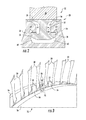
- FIG. 2 is a partial sectional view of an embodiment of a root and attachment slot configuration for circumferential entry rotor blades
- FIG. 3 is a partial perspective view of an exemplary rotor disk including final or load-in spaces into which a locking spacer assembly may be inserted;
- FIG. 4 is a top view of a portion of the rotor disk as shown in FIG. 3 , according to one embodiment of the present invention.
- FIG. 5 is a is an exploded view of the components of an embodiment of the locking spacer assembly in accordance with various aspects of the present invention.
- FIG. 6 is a top view of the locking spacer assembly as shown in FIG. 5 , according to one embodiment of the present invention.
- FIG. 7 is a top view of the locking spacer assembly as shown in FIG. 5 , according to one embodiment of the present invention.
- FIG. 8 is a top view of the locking spacer assembly as shown in FIG. 5 , according to one embodiment of the present invention.
- FIG. 9 , FIG. 10 , FIG. 11 , FIG. 12 , FIG. 13 and FIG. 14 are sequential assembly views of a locking spacer assembly according to one embodiment of the present invention.
- FIG. 15 is a partial perspective view of a portion of a rotor disk including a locking spacer assembly according to one embodiment of the present invention.
- upstream and downstream refer to the relative direction with respect to fluid flow in a fluid pathway.
- upstream refers to the direction from which the fluid flows
- downstream refers to the direction to which the fluid flows.
- radially refers to the relative direction in a plane that is substantially perpendicular to an axial centerline of a particular component
- axially refers to the relative direction in a plane that is substantially parallel to an axial centerline of a particular component.
- FIG. 1 provides a functional diagram of one embodiment of a turbomachine, in this case an exemplary gas turbine 10 which may incorporate various embodiments of the present invention.
- the gas turbine 10 generally includes a compressor section 12 including a compressor 14 disposed at an upstream end of the gas turbine 10 , a combustion section 16 having at least one combustor 18 downstream from the compressor 14 , and a turbine section 20 including a turbine 22 that is downstream from the combustion section 14 .
- a shaft 24 extends along an axial centerline 26 of the gas turbine 10 at least partially through the compressor 14 and/or the turbine 22 .
- the shaft 24 may comprise of a plurality of individual shafts.
- Each rotor disk 28 is configured to receive a plurality of radially extending rotor blades 30 that are circumferentially spaced around and removably fixed to the rotor disk 28 .
- the rotor blades 30 may be configured for use within the compressor 14 such as a compressor rotor blade 32 or for use within the turbine 22 such as a turbine bucket or turbine rotor blade 34 .
- Each blade 30 has a longitudinal centerline axis 36 and includes an airfoil portion 38 having a leading edge 40 and a trailing edge 42 .
- a working fluid 44 such as air is routed into the compressor 14 where it is progressively compressed in part by the compressor rotor blades 32 as it is routed towards the combustion section 16 .
- a compressed working fluid 46 flows from the compressor 14 and is supplied to the combustion section 16 .
- the compressed working fluid 46 is distributed to each of the combustors 18 where it is mixed with a fuel to provide a combustible mixture.
- the combustible mixture is burned to produce combustion gases 48 at a relatively high temperature and high velocity.
- the combustion gases 48 are routed through the turbine 22 where thermal and kinetic energy is transferred to the turbine rotor blades 34 , thereby causing the shaft 24 to rotate.
- the shaft 24 is coupled to a generator (not shown) to produce electricity.
- FIG. 2 is an enlarged cross section view of a portion of an exemplary rotor disk 28 including an exemplary rotor blade 30 having a T-type root and attachment slot configuration.
- each rotor blade 30 also may include a platform 50 that provides a portion of a radially inner boundary for airflow, combustion gas flow or other fluid flow such as steam over the airfoils 38 during operation of the gas turbine 10 .
- each rotor blade 30 includes an integral root portion 52 that extends radially inward from the platform 50 .
- the root portion 52 slides into and along a circumferentially extending attachment slot 54 at least partially defined by forward and aft hoop or post components 56 of the rotor disk 28 , as is generally known in the art.
- the circumferentially extending attachment slot 54 may be machined, cast or otherwise defined by the rotor disk 28 .
- the root portion 52 may include protrusions 58 that are received into lateral recesses 60 defined within the attachment slot 54 and at least partially defined by recessed wall portions 62 of the post components 56 .
- the forward and aft post components 56 and/or the rotor disk 28 may further define sidewall portions 64 of the attachment slot 54 . It should be readily appreciated that the configuration of the root portion 52 and attachment slot 54 provided in FIG. 2 is for illustrative purposes only, and that the root and slot configuration may vary widely within the scope and spirit of the present subject matter.
- FIG. 3 is a partial perspective view of a portion of an exemplary rotor disk 28 , and particularly illustrates a plurality of the rotor blades 30 configured in an attachment slot 54 ( FIG. 2 ) between the forward and aft post components 56 of the rotor disk 28 .
- each of the rotor blades 30 includes a platform 50 .
- conventional spacers 64 are disposed between the platforms 50 of adjacent rotor blades 30 , as is generally known in the art.
- FIG. 4 is a top view of a portion of the rotor disk 28 as shown in FIG. 3 , according to one embodiment of the present invention.
- one or more final or load-in spaces 68 having a circumferential width 70 , are defined between adjacent rotor blade 30 platforms 50 .
- the final or load-in spaces 68 are generally used to insert the rotor blades 30 into the attachment slot 54 during assembly and/or disassembly of the rotor blades 30 to the rotor disk 28 .
- the final or load-in spaces 68 can be filled by various embodiments of a locking spacer assembly 100 which is described in greater detail below.
- the locking spacer assembly 100 can be used to fill final spaces 68 between platforms 50 of adjacent rotor blades 30 including the compressor rotor blades 32 located within the compressor 14 and/or the turbine rotor blades 34 located within the turbine 22 .
- the locking spacer assembly 100 will be generally described below as being installed between platforms 50 of adjacent rotor blades 30 , wherein the platforms 50 may be part of a compressor rotor blade 32 or a turbine rotor blade 34 so as to fully encompass both applications.
- FIG. 5 is an exploded view of the components of a locking spacer assembly 100 herein referred to as “assembly 100 ” according to one embodiment of the present invention.
- the assembly 100 includes a first end piece 102 , a second end piece 104 and a fastener 106 .
- the first end piece 102 and the second end piece 104 are configured to fit into the final or load-in spaces 68 ( FIG. 2 ) between the platforms 50 of adjacent rotor blades 30 ( FIG. 4 ).
- the end pieces 102 , 104 thus, have any dimensional configuration such that the width, length, thickness, or any other characteristics enables the end pieces 102 , 104 to be inserted between the platforms 50 .
- the end pieces 102 , 104 may generally have a circumferential width 108 ( FIG. 4 ) in order to fit snugly between the platforms 50 of adjacent airfoils or rotor blades 30 .
- the first end piece 102 comprises a platform portion 110 and a root portion 112 .
- the platform portion 110 generally has a radial height 114 , an axial length 116 and a circumferential width 118 .
- the root portion 112 extends radially inwardly from the platform portion 110 .
- the platform portion 110 and the root portion 112 define a first inner surface 120 .
- the first inner surface 120 is angled at an angle ⁇ with respect to a radially extending plane that is perpendicular to an axial plane and/or axial centerline that extends through the locker spacer assembly 100 and/or the first end piece 102 .
- the angle ⁇ the first inner surface 120 is greater than zero degrees and less than ninety degrees.
- the root portion 112 defines a first projection 122 .
- the first projection 122 has an outer profile that is adapted to project into a first lateral recess 124 of the attachment slot 54 .
- the first projection 122 may have a top portion that is substantially curved to mirror the curve of the post components 56 .
- the first projection 122 may include a bottom portion that extends outwardly at the corner formed between the post components 56 and the first lateral recess 124 so as to project into the illustrated t-type attachment slot 54 .
- the first projection 122 can have any desired outer profile and need not have the particular outer profile illustrated in FIG. 5 .
- the outer profile of the first projection 122 will depend in large part on the particular shape and configuration of the attachment slot 54 .
- an arcuate groove 126 or other stress relief feature such as a blend or fillet is defined by the first end piece 102 proximate to a location where the first projection 122 is defined or extends generally axially outwardly from the root portion 112 of the first end piece 102 .
- the arcuate groove 126 may be included to provide a point of low stress or a location for stress relief on the first end piece 102 .
- the arcuate groove 126 may be located on the root portion 112 at a corner formed between the forward post component 56 and the first lateral recess 124 .
- the second end piece 104 is configured to fit between the first inner surface 120 of the first end piece 102 and one of the sidewall portions 64 of the attachment slot 54 .
- the second end piece 104 comprises a platform portion 128 and a root portion 130 .
- the platform portion 128 generally has a radial height 132 , an axial length 134 and a circumferential width 136 .
- the root portion 130 extends radially inwardly from the platform portion 128 .
- the platform portion 128 and the root portion 130 define a second inner surface 138 .
- the second inner surface 138 is configured to mate with the first inner surface 120 .
- the first and second inner surfaces 120 , 138 may be flat or congruently curved or slotted.
- the second inner surface 138 is angled with respect to a radially extending plane that is perpendicular to an axial plane that extends through the locker spacer assembly 100 and/or the second end piece 104 .
- the angle of the second inner surface 138 is greater than zero degrees and less than ninety degrees.
- the angle of the first inner surface 120 and the angle of the second inner surface 138 are substantially similar.
- the angle of the first inner surface 120 and the angle of the second inner surface 138 are congruent.
- the root portion 130 defines a second projection 140 .
- the second projection 140 has an outer profile that is adapted to project into a second lateral recess 142 of the attachment slot 54 .
- the second projection 140 may have a top portion that is substantially curved to mirror the curve of the post components 56 .
- the second projection 140 may include a bottom portion that extends outwardly at the corner formed between the post components 56 and the second lateral recess 142 so as to project into the illustrated t-type attachment slot 54 .
- the second projection 140 can have any desired profile and need not have the particular profile illustrated in FIG. 5 .
- the profile of the second projection 140 will depend in large part on the particular shape and configuration of the attachment slot 54 .
- an arcuate groove 144 or other stress relief feature such as a blend or fillet is defined by the second end piece 104 proximate to a location where the second projection 140 is defined or extends generally axially outwardly from the root portion 130 of the second end piece 104 .
- the arcuate groove 144 may be included to provide a point of low stress or a location for stress relief on the second end piece 104 .
- the arcuate groove 144 may be located on the root portion 130 at corners formed between the aft post component 56 and the second lateral recess 142 .
- the second projection 140 can have any desired profile and need not have the particular profile illustrated in FIG. 5 .
- the profile of the second projection 140 will depend in large part on the particular shape and configuration of the attachment slot 54 .
- a borehole 146 extends continuously through the first end piece 102 and the second end piece 104 .
- the borehole 146 may be at least partially defined by the first and second end pieces 102 , 104 .
- the borehole 146 extends continuously through the first end piece 102 and the second end piece 104 .
- the borehole 146 extends through the platform portion 110 of the first end piece 102 and the root portion 130 of the second end piece 104 .
- the borehole 146 extends through a bottom wall 148 defined by the root portion 130 of the second end piece 104 .
- the borehole 146 extends generally radially through the first and second end pieces 102 , 104 .
- the borehole 146 may be threaded in at least one of the first end piece 102 or the second end piece 104 .
- the borehole 146 includes a counter bore 150 or step feature defined within the platform portion 110 of the first end piece 102 .
- the fastener 106 may include any fastener such as a screw, bolt, pin or the like that extends through the borehole 146 .
- the fastener 106 may include threads 152 disposed along the shank of the fastener 106 .
- the threads 152 may be complementary to the threads defined within the first and/or second end pieces 102 , 104 .
- FIG. 6 , FIG. 7 and FIG. 8 provide top views of the locker spacer assembly 100 as shown in FIG. 5 , according to various embodiments of the present invention.
- a recess 154 may be formed on the platform portion 110 of the first end piece 102 .
- the recess 154 may be formed on the platform portion 128 of the second end piece 104 .
- the recess 154 may be configured to receive a complimentary collar 156 formed on the platform portion 110 of the first end piece 102 or on the platform portion 128 of the second end piece 104 when the first end piece 102 and the second end piece 104 are installed into the attachment slot 54 .
- the recess 154 and the collar 156 may be rectangular, trapezoidal, arcuate or any shape so as to create an interlocking action between the first and second end pieces 102 , 104 .
- FIG. 9 , FIG. 10 , FIG. 11 , FIG. 12 , FIG. 13 and FIG. 14 are sequential assembly views of a locking spacer assembly 100 according to one embodiment of the present invention.
- the root portion 130 of the second end piece 104 is lowered into the attachment slot 54 between the opposing sidewall portions 64 .
- the second projection 140 is positioned within the second lateral recess 142 .
- the root portion 112 of first end piece 102 is lowered into the attachment slot 54 adjacent to the second end piece 104 such that the first inner surface 120 and the second inner surface 138 face one another.
- the substantially similar or congruent angles of the first and second inner surfaces 120 , 136 allow the first end piece 102 to be positioned into the attachment slot 54 and the first projection 122 to be inserted into the first lateral recess 124 with the second end piece 104 being in position within the attachment slot 54 .
- the fastener 106 is then inserted into the borehole 146 and turned, threaded, hammered or otherwise translated through the borehole 146 until the fastener 106 engages with the second end piece 102 , thereby locking the locking spacer assembly into position and securing the adjacent rotor blades 30 to the rotor disk 28 .
- the fastener 106 extends through the bottom wall 148 of the second end piece 104 .
- the fastener 106 may engage a bottom wall portion 158 of the attachment slot 54 , thus creating an upwardly or radially acting force 160 between the first and second projections 120 , 130 and upper wall portions 162 of the first and second lateral recesses 124 , 140 , thereby locking the locking spacer assembly into position and securing the adjacent rotor blades 30 to the rotor disk 28 .
- disassembly of the locker spacer assembly 100 may be achieved by simply reversing the assembly steps described herein.
- FIG. 15 is a partial perspective view of a portion of a rotor disk 28 including the locking spacer assembly 100 installed into the attachment slot 54 .
Landscapes
- Engineering & Computer Science (AREA)
- Mechanical Engineering (AREA)
- General Engineering & Computer Science (AREA)
- Structures Of Non-Positive Displacement Pumps (AREA)
- Turbine Rotor Nozzle Sealing (AREA)
Priority Applications (5)
| Application Number | Priority Date | Filing Date | Title |
|---|---|---|---|
| US14/055,091 US9512732B2 (en) | 2013-10-16 | 2013-10-16 | Locking spacer assembly inserted between rotor blades |
| DE201410114697 DE102014114697A1 (de) | 2013-10-16 | 2014-10-09 | Verriegelnde Abstandshalteranordnung |
| JP2014207662A JP6563631B2 (ja) | 2013-10-16 | 2014-10-09 | ロック用スペーサアセンブリ |
| CH01574/14A CH708769A2 (de) | 2013-10-16 | 2014-10-15 | Verriegelnde Abstandshalteranordnung zur Einführung in einen umlaufenden Befestigungsschlitz zwischen Plattformen benachbarter Laufschaufeln. |
| CN201410858078.7A CN104675448B (zh) | 2013-10-16 | 2014-10-16 | 锁定间隔组件 |
Applications Claiming Priority (1)
| Application Number | Priority Date | Filing Date | Title |
|---|---|---|---|
| US14/055,091 US9512732B2 (en) | 2013-10-16 | 2013-10-16 | Locking spacer assembly inserted between rotor blades |
Publications (2)
| Publication Number | Publication Date |
|---|---|
| US20150101347A1 US20150101347A1 (en) | 2015-04-16 |
| US9512732B2 true US9512732B2 (en) | 2016-12-06 |
Family
ID=52738176
Family Applications (1)
| Application Number | Title | Priority Date | Filing Date |
|---|---|---|---|
| US14/055,091 Expired - Fee Related US9512732B2 (en) | 2013-10-16 | 2013-10-16 | Locking spacer assembly inserted between rotor blades |
Country Status (5)
| Country | Link |
|---|---|
| US (1) | US9512732B2 (enExample) |
| JP (1) | JP6563631B2 (enExample) |
| CN (1) | CN104675448B (enExample) |
| CH (1) | CH708769A2 (enExample) |
| DE (1) | DE102014114697A1 (enExample) |
Cited By (5)
| Publication number | Priority date | Publication date | Assignee | Title |
|---|---|---|---|---|
| US10858941B2 (en) * | 2018-05-23 | 2020-12-08 | Safran Aircraft Engines | Shutter for turbine machine having an absent rectifier blade |
| US11319821B2 (en) * | 2018-04-18 | 2022-05-03 | Siemens Energy Global GmbH & Co. KG | Locking spacer assembly, corresponding blade assembly, method for installing a locking spacer |
| US11396822B2 (en) * | 2020-08-25 | 2022-07-26 | General Electric Company | Blade dovetail and retention apparatus |
| US20250215802A1 (en) * | 2022-04-08 | 2025-07-03 | Siemens Energy Global GmbH & Co. KG | Locking spacer assemblies and method for installing a locking spacer assembly |
| US12435637B2 (en) * | 2023-04-04 | 2025-10-07 | Ge Infrastructure Technology Llc | Method for turbine blade and assembly with dovetail arrangement for enlarged rotor groove |
Families Citing this family (10)
| Publication number | Priority date | Publication date | Assignee | Title |
|---|---|---|---|---|
| US9341071B2 (en) | 2013-10-16 | 2016-05-17 | General Electric Company | Locking spacer assembly |
| US9518471B2 (en) | 2013-10-16 | 2016-12-13 | General Electric Company | Locking spacer assembly |
| US9464531B2 (en) | 2013-10-16 | 2016-10-11 | General Electric Company | Locking spacer assembly |
| US9416670B2 (en) * | 2013-10-16 | 2016-08-16 | General Electric Company | Locking spacer assembly |
| US10047865B2 (en) * | 2015-12-07 | 2018-08-14 | General Electric Company | Steam turbine rotor seal radial key member, related assembly and steam turbine |
| US10519970B2 (en) * | 2017-02-09 | 2019-12-31 | DOOSAN Heavy Industries Construction Co., LTD | Compressor blade locking mechanism in disk with tangential groove |
| US11359501B2 (en) | 2018-03-28 | 2022-06-14 | Siemens Energy Global GmbH & Co. KG | Locking spacer assembly, corresponding blade assembly, method for installing a locking spacer |
| US11486261B2 (en) | 2020-03-31 | 2022-11-01 | General Electric Company | Turbine circumferential dovetail leakage reduction |
| JP7347404B2 (ja) | 2020-11-30 | 2023-09-20 | 株式会社デンソー | 電力変換装置 |
| US12221899B2 (en) * | 2023-06-15 | 2025-02-11 | General Electric Company | Methods and apparatuses for blade locking |
Citations (26)
| Publication number | Priority date | Publication date | Assignee | Title |
|---|---|---|---|---|
| US2857134A (en) * | 1954-03-17 | 1958-10-21 | Parsons C A & Co Ltd | Assembly of blades for turbines and the like |
| US3627448A (en) | 1969-12-31 | 1971-12-14 | Westinghouse Electric Corp | Locking arrangement for side-entry blades |
| US3721506A (en) * | 1971-05-25 | 1973-03-20 | Gen Electric | Split-nut blade locking assembly |
| US4684325A (en) | 1985-02-12 | 1987-08-04 | Rolls-Royce Plc | Turbomachine rotor blade fixings and method for assembly |
| US4859149A (en) | 1989-03-10 | 1989-08-22 | General Motors Corporation | Blade locking system |
| USH1258H (en) | 1992-09-16 | 1993-12-07 | The United States Of America As Represented By The Secretary Of The Air Force | Blade lock screw |
| US6135717A (en) | 1998-06-17 | 2000-10-24 | Abb Patent Gmbh | Lock for moving blades of a turbine rotor |
| US20010022936A1 (en) | 2000-03-14 | 2001-09-20 | Achim Zimmermamm | Blade lock and process for manufacturing a blade lock |
| US6638006B2 (en) | 2001-02-03 | 2003-10-28 | Rolls-Royce Plc | Turbine blade locking device |
| US20040037703A1 (en) | 2001-12-21 | 2004-02-26 | Paolo Arinci | System for connecting and locking rotor blades of an axial compressor |
| US6929453B2 (en) | 2003-12-11 | 2005-08-16 | Siemens Westinghouse Power Corporation | Locking spacer assembly for slotted turbine component |
| US7114927B2 (en) | 2003-10-06 | 2006-10-03 | Alstom Technology Ltd. | Fixing method for the blading of a fluid-flow machine and fixing arrangement |
| US20060248900A1 (en) * | 2005-05-05 | 2006-11-09 | Gabriel Suciu | Accessory gearbox |
| US20070280831A1 (en) | 2006-06-05 | 2007-12-06 | United Technologies Corporation | Rotor disk and blade arrangement |
| US7435055B2 (en) | 2005-03-29 | 2008-10-14 | Siemens Power Generation, Inc. | Locking spacer assembly for a turbine engine |
| US20090016889A1 (en) | 2006-01-02 | 2009-01-15 | Joachim Krutzfeldt | Locking Sub-Assembly for Closing The Remaining Gap Between The First and The Last blade of a Blade Ring Which Are Inserted in a Circumferential Groove of a Turbomachine, and Corresponding Turbomachine |
| US7581931B2 (en) | 2006-10-13 | 2009-09-01 | Siemens Energy, Inc. | Gas turbine belly band seal anti-rotation structure |
| US20110110782A1 (en) | 2009-11-11 | 2011-05-12 | General Electric Company | Locking spacer assembly for a circumferential entry airfoil attachment system |
| US20110164983A1 (en) | 2010-01-05 | 2011-07-07 | General Electric Company | Locking Spacer Assembly |
| US20110255978A1 (en) * | 2010-04-16 | 2011-10-20 | Brian Denver Potter | Locking Assembly For Circumferential Attachments |
| US8176598B2 (en) | 2009-08-03 | 2012-05-15 | General Electric Company | Locking spacer assembly for a circumferential dovetail rotor blade attachment system |
| US20150101349A1 (en) | 2013-10-16 | 2015-04-16 | General Electric Company | Locking spacer assembly |
| US20150101351A1 (en) | 2013-10-16 | 2015-04-16 | General Electric Company | Locking spacer assembly |
| US20150101350A1 (en) | 2013-10-16 | 2015-04-16 | General Electric Company | Locking spacer assembly |
| US20150101348A1 (en) | 2013-10-16 | 2015-04-16 | General Electric Company | Locking spacer assembly |
| US20150101346A1 (en) | 2013-10-16 | 2015-04-16 | General Electric Company | Locking spacer assembly |
Family Cites Families (2)
| Publication number | Priority date | Publication date | Assignee | Title |
|---|---|---|---|---|
| DE10310431A1 (de) * | 2003-03-11 | 2004-09-23 | Alstom Technology Ltd | Rotor-Schluss |
| EP1803899A1 (de) * | 2006-01-02 | 2007-07-04 | Siemens Aktiengesellschaft | Schlussbaugruppe für einen Schaufelkranz einer Strömungsmaschine |
-
2013
- 2013-10-16 US US14/055,091 patent/US9512732B2/en not_active Expired - Fee Related
-
2014
- 2014-10-09 JP JP2014207662A patent/JP6563631B2/ja not_active Expired - Fee Related
- 2014-10-09 DE DE201410114697 patent/DE102014114697A1/de not_active Ceased
- 2014-10-15 CH CH01574/14A patent/CH708769A2/de not_active Application Discontinuation
- 2014-10-16 CN CN201410858078.7A patent/CN104675448B/zh not_active Expired - Fee Related
Patent Citations (26)
| Publication number | Priority date | Publication date | Assignee | Title |
|---|---|---|---|---|
| US2857134A (en) * | 1954-03-17 | 1958-10-21 | Parsons C A & Co Ltd | Assembly of blades for turbines and the like |
| US3627448A (en) | 1969-12-31 | 1971-12-14 | Westinghouse Electric Corp | Locking arrangement for side-entry blades |
| US3721506A (en) * | 1971-05-25 | 1973-03-20 | Gen Electric | Split-nut blade locking assembly |
| US4684325A (en) | 1985-02-12 | 1987-08-04 | Rolls-Royce Plc | Turbomachine rotor blade fixings and method for assembly |
| US4859149A (en) | 1989-03-10 | 1989-08-22 | General Motors Corporation | Blade locking system |
| USH1258H (en) | 1992-09-16 | 1993-12-07 | The United States Of America As Represented By The Secretary Of The Air Force | Blade lock screw |
| US6135717A (en) | 1998-06-17 | 2000-10-24 | Abb Patent Gmbh | Lock for moving blades of a turbine rotor |
| US20010022936A1 (en) | 2000-03-14 | 2001-09-20 | Achim Zimmermamm | Blade lock and process for manufacturing a blade lock |
| US6638006B2 (en) | 2001-02-03 | 2003-10-28 | Rolls-Royce Plc | Turbine blade locking device |
| US20040037703A1 (en) | 2001-12-21 | 2004-02-26 | Paolo Arinci | System for connecting and locking rotor blades of an axial compressor |
| US7114927B2 (en) | 2003-10-06 | 2006-10-03 | Alstom Technology Ltd. | Fixing method for the blading of a fluid-flow machine and fixing arrangement |
| US6929453B2 (en) | 2003-12-11 | 2005-08-16 | Siemens Westinghouse Power Corporation | Locking spacer assembly for slotted turbine component |
| US7435055B2 (en) | 2005-03-29 | 2008-10-14 | Siemens Power Generation, Inc. | Locking spacer assembly for a turbine engine |
| US20060248900A1 (en) * | 2005-05-05 | 2006-11-09 | Gabriel Suciu | Accessory gearbox |
| US20090016889A1 (en) | 2006-01-02 | 2009-01-15 | Joachim Krutzfeldt | Locking Sub-Assembly for Closing The Remaining Gap Between The First and The Last blade of a Blade Ring Which Are Inserted in a Circumferential Groove of a Turbomachine, and Corresponding Turbomachine |
| US20070280831A1 (en) | 2006-06-05 | 2007-12-06 | United Technologies Corporation | Rotor disk and blade arrangement |
| US7581931B2 (en) | 2006-10-13 | 2009-09-01 | Siemens Energy, Inc. | Gas turbine belly band seal anti-rotation structure |
| US8176598B2 (en) | 2009-08-03 | 2012-05-15 | General Electric Company | Locking spacer assembly for a circumferential dovetail rotor blade attachment system |
| US20110110782A1 (en) | 2009-11-11 | 2011-05-12 | General Electric Company | Locking spacer assembly for a circumferential entry airfoil attachment system |
| US20110164983A1 (en) | 2010-01-05 | 2011-07-07 | General Electric Company | Locking Spacer Assembly |
| US20110255978A1 (en) * | 2010-04-16 | 2011-10-20 | Brian Denver Potter | Locking Assembly For Circumferential Attachments |
| US20150101349A1 (en) | 2013-10-16 | 2015-04-16 | General Electric Company | Locking spacer assembly |
| US20150101351A1 (en) | 2013-10-16 | 2015-04-16 | General Electric Company | Locking spacer assembly |
| US20150101350A1 (en) | 2013-10-16 | 2015-04-16 | General Electric Company | Locking spacer assembly |
| US20150101348A1 (en) | 2013-10-16 | 2015-04-16 | General Electric Company | Locking spacer assembly |
| US20150101346A1 (en) | 2013-10-16 | 2015-04-16 | General Electric Company | Locking spacer assembly |
Cited By (5)
| Publication number | Priority date | Publication date | Assignee | Title |
|---|---|---|---|---|
| US11319821B2 (en) * | 2018-04-18 | 2022-05-03 | Siemens Energy Global GmbH & Co. KG | Locking spacer assembly, corresponding blade assembly, method for installing a locking spacer |
| US10858941B2 (en) * | 2018-05-23 | 2020-12-08 | Safran Aircraft Engines | Shutter for turbine machine having an absent rectifier blade |
| US11396822B2 (en) * | 2020-08-25 | 2022-07-26 | General Electric Company | Blade dovetail and retention apparatus |
| US20250215802A1 (en) * | 2022-04-08 | 2025-07-03 | Siemens Energy Global GmbH & Co. KG | Locking spacer assemblies and method for installing a locking spacer assembly |
| US12435637B2 (en) * | 2023-04-04 | 2025-10-07 | Ge Infrastructure Technology Llc | Method for turbine blade and assembly with dovetail arrangement for enlarged rotor groove |
Also Published As
| Publication number | Publication date |
|---|---|
| CH708769A2 (de) | 2015-04-30 |
| JP2015078692A (ja) | 2015-04-23 |
| CN104675448A (zh) | 2015-06-03 |
| DE102014114697A1 (de) | 2015-04-16 |
| JP6563631B2 (ja) | 2019-08-21 |
| CN104675448B (zh) | 2017-11-28 |
| US20150101347A1 (en) | 2015-04-16 |
Similar Documents
| Publication | Publication Date | Title |
|---|---|---|
| US9512732B2 (en) | Locking spacer assembly inserted between rotor blades | |
| US9464531B2 (en) | Locking spacer assembly | |
| US9416670B2 (en) | Locking spacer assembly | |
| US9518471B2 (en) | Locking spacer assembly | |
| US9341071B2 (en) | Locking spacer assembly | |
| US20150101350A1 (en) | Locking spacer assembly | |
| US8523529B2 (en) | Locking spacer assembly for a circumferential entry airfoil attachment system | |
| US8206116B2 (en) | Method for loading and locking tangential rotor blades and blade design | |
| US10480338B2 (en) | Bladed rotor arrangement including axial projection | |
| JP6408888B2 (ja) | タービンバケット閉鎖組立体及びその組立方法 | |
| US20070059182A1 (en) | Turbine airfoil with curved squealer tip | |
| US10830082B2 (en) | Systems including rotor blade tips and circumferentially grooved shrouds | |
| US20100166561A1 (en) | Turbine blade root configurations | |
| US20150204237A1 (en) | Turbine blade and method for enhancing life of the turbine blade | |
| US20150098832A1 (en) | Method and system for relieving turbine rotor blade dovetail stress | |
| EP2918785B1 (en) | A bladed rotor | |
| WO2013181006A1 (en) | Turbine cooling apparatus | |
| US20160040537A1 (en) | Turbine blade mid-span shroud assembly | |
| KR101513062B1 (ko) | 증기터빈 | |
| KR101529532B1 (ko) | 증기터빈 | |
| KR101513061B1 (ko) | 증기터빈 | |
| US20170254211A1 (en) | Bladed rotor arrangement | |
| US20180094529A1 (en) | Attachment system for a turbine airfoil usable in a gas turbine engine |
Legal Events
| Date | Code | Title | Description |
|---|---|---|---|
| AS | Assignment |
Owner name: GENERAL ELECTRIC COMPANY, NEW YORK Free format text: ASSIGNMENT OF ASSIGNORS INTEREST;ASSIGNORS:POTTER, BRIAN DENVER;HEALY, MICHAEL JAMES;HANSEN, CHRISTIAN MICHAEL;REEL/FRAME:031415/0909 Effective date: 20131010 |
|
| STCF | Information on status: patent grant |
Free format text: PATENTED CASE |
|
| MAFP | Maintenance fee payment |
Free format text: PAYMENT OF MAINTENANCE FEE, 4TH YEAR, LARGE ENTITY (ORIGINAL EVENT CODE: M1551); ENTITY STATUS OF PATENT OWNER: LARGE ENTITY Year of fee payment: 4 |
|
| FEPP | Fee payment procedure |
Free format text: MAINTENANCE FEE REMINDER MAILED (ORIGINAL EVENT CODE: REM.); ENTITY STATUS OF PATENT OWNER: LARGE ENTITY |
|
| LAPS | Lapse for failure to pay maintenance fees |
Free format text: PATENT EXPIRED FOR FAILURE TO PAY MAINTENANCE FEES (ORIGINAL EVENT CODE: EXP.); ENTITY STATUS OF PATENT OWNER: LARGE ENTITY |
|
| STCH | Information on status: patent discontinuation |
Free format text: PATENT EXPIRED DUE TO NONPAYMENT OF MAINTENANCE FEES UNDER 37 CFR 1.362 |
|
| FP | Lapsed due to failure to pay maintenance fee |
Effective date: 20241206 |