US9510744B2 - Endoscope - Google Patents
Endoscope Download PDFInfo
- Publication number
- US9510744B2 US9510744B2 US13/158,139 US201113158139A US9510744B2 US 9510744 B2 US9510744 B2 US 9510744B2 US 201113158139 A US201113158139 A US 201113158139A US 9510744 B2 US9510744 B2 US 9510744B2
- Authority
- US
- United States
- Prior art keywords
- heat
- heat pipe
- shaft
- endoscope
- headpiece
- Prior art date
- Legal status (The legal status is an assumption and is not a legal conclusion. Google has not performed a legal analysis and makes no representation as to the accuracy of the status listed.)
- Active, expires
Links
- 238000001816 cooling Methods 0.000 claims abstract description 40
- 230000008878 coupling Effects 0.000 claims description 68
- 238000010168 coupling process Methods 0.000 claims description 68
- 238000005859 coupling reaction Methods 0.000 claims description 68
- 230000005540 biological transmission Effects 0.000 claims description 19
- 230000003287 optical effect Effects 0.000 claims description 9
- RYGMFSIKBFXOCR-UHFFFAOYSA-N Copper Chemical compound [Cu] RYGMFSIKBFXOCR-UHFFFAOYSA-N 0.000 description 9
- 230000008901 benefit Effects 0.000 description 7
- 239000010949 copper Substances 0.000 description 7
- 229910052802 copper Inorganic materials 0.000 description 7
- 238000009413 insulation Methods 0.000 description 7
- 239000002609 medium Substances 0.000 description 6
- 238000001356 surgical procedure Methods 0.000 description 6
- 241001465754 Metazoa Species 0.000 description 5
- 239000004411 aluminium Substances 0.000 description 5
- XAGFODPZIPBFFR-UHFFFAOYSA-N aluminium Chemical compound [Al] XAGFODPZIPBFFR-UHFFFAOYSA-N 0.000 description 5
- 229910052782 aluminium Inorganic materials 0.000 description 5
- 239000002826 coolant Substances 0.000 description 5
- 238000004519 manufacturing process Methods 0.000 description 5
- 230000032258 transport Effects 0.000 description 4
- 239000004020 conductor Substances 0.000 description 3
- 239000000463 material Substances 0.000 description 3
- 229940127554 medical product Drugs 0.000 description 3
- ORQBXQOJMQIAOY-UHFFFAOYSA-N nobelium Chemical compound [No] ORQBXQOJMQIAOY-UHFFFAOYSA-N 0.000 description 3
- 239000007787 solid Substances 0.000 description 3
- 238000009834 vaporization Methods 0.000 description 3
- 230000008016 vaporization Effects 0.000 description 3
- 230000008859 change Effects 0.000 description 2
- 239000011248 coating agent Substances 0.000 description 2
- 238000000576 coating method Methods 0.000 description 2
- 230000000694 effects Effects 0.000 description 2
- 239000012530 fluid Substances 0.000 description 2
- 238000010438 heat treatment Methods 0.000 description 2
- 239000007788 liquid Substances 0.000 description 2
- 239000000126 substance Substances 0.000 description 2
- 239000006163 transport media Substances 0.000 description 2
- 238000004026 adhesive bonding Methods 0.000 description 1
- 230000002411 adverse Effects 0.000 description 1
- 230000033228 biological regulation Effects 0.000 description 1
- 230000001419 dependent effect Effects 0.000 description 1
- 230000005484 gravity Effects 0.000 description 1
- 230000017525 heat dissipation Effects 0.000 description 1
- 230000010354 integration Effects 0.000 description 1
- 238000012423 maintenance Methods 0.000 description 1
- 230000005855 radiation Effects 0.000 description 1
- 238000005476 soldering Methods 0.000 description 1
- 229910052724 xenon Inorganic materials 0.000 description 1
- FHNFHKCVQCLJFQ-UHFFFAOYSA-N xenon atom Chemical compound [Xe] FHNFHKCVQCLJFQ-UHFFFAOYSA-N 0.000 description 1
Images


Classifications
-
- A—HUMAN NECESSITIES
- A61—MEDICAL OR VETERINARY SCIENCE; HYGIENE
- A61B—DIAGNOSIS; SURGERY; IDENTIFICATION
- A61B1/00—Instruments for performing medical examinations of the interior of cavities or tubes of the body by visual or photographical inspection, e.g. endoscopes; Illuminating arrangements therefor
- A61B1/12—Instruments for performing medical examinations of the interior of cavities or tubes of the body by visual or photographical inspection, e.g. endoscopes; Illuminating arrangements therefor with cooling or rinsing arrangements
-
- A—HUMAN NECESSITIES
- A61—MEDICAL OR VETERINARY SCIENCE; HYGIENE
- A61B—DIAGNOSIS; SURGERY; IDENTIFICATION
- A61B1/00—Instruments for performing medical examinations of the interior of cavities or tubes of the body by visual or photographical inspection, e.g. endoscopes; Illuminating arrangements therefor
- A61B1/00064—Constructional details of the endoscope body
- A61B1/00066—Proximal part of endoscope body, e.g. handles
-
- A—HUMAN NECESSITIES
- A61—MEDICAL OR VETERINARY SCIENCE; HYGIENE
- A61B—DIAGNOSIS; SURGERY; IDENTIFICATION
- A61B1/00—Instruments for performing medical examinations of the interior of cavities or tubes of the body by visual or photographical inspection, e.g. endoscopes; Illuminating arrangements therefor
- A61B1/00112—Connection or coupling means
- A61B1/00121—Connectors, fasteners and adapters, e.g. on the endoscope handle
-
- A—HUMAN NECESSITIES
- A61—MEDICAL OR VETERINARY SCIENCE; HYGIENE
- A61B—DIAGNOSIS; SURGERY; IDENTIFICATION
- A61B1/00—Instruments for performing medical examinations of the interior of cavities or tubes of the body by visual or photographical inspection, e.g. endoscopes; Illuminating arrangements therefor
- A61B1/06—Instruments for performing medical examinations of the interior of cavities or tubes of the body by visual or photographical inspection, e.g. endoscopes; Illuminating arrangements therefor with illuminating arrangements
- A61B1/0661—Endoscope light sources
- A61B1/0676—Endoscope light sources at distal tip of an endoscope
-
- A—HUMAN NECESSITIES
- A61—MEDICAL OR VETERINARY SCIENCE; HYGIENE
- A61B—DIAGNOSIS; SURGERY; IDENTIFICATION
- A61B1/00—Instruments for performing medical examinations of the interior of cavities or tubes of the body by visual or photographical inspection, e.g. endoscopes; Illuminating arrangements therefor
- A61B1/06—Instruments for performing medical examinations of the interior of cavities or tubes of the body by visual or photographical inspection, e.g. endoscopes; Illuminating arrangements therefor with illuminating arrangements
- A61B1/0661—Endoscope light sources
- A61B1/0684—Endoscope light sources using light emitting diodes [LED]
-
- A—HUMAN NECESSITIES
- A61—MEDICAL OR VETERINARY SCIENCE; HYGIENE
- A61B—DIAGNOSIS; SURGERY; IDENTIFICATION
- A61B1/00—Instruments for performing medical examinations of the interior of cavities or tubes of the body by visual or photographical inspection, e.g. endoscopes; Illuminating arrangements therefor
- A61B1/12—Instruments for performing medical examinations of the interior of cavities or tubes of the body by visual or photographical inspection, e.g. endoscopes; Illuminating arrangements therefor with cooling or rinsing arrangements
- A61B1/128—Instruments for performing medical examinations of the interior of cavities or tubes of the body by visual or photographical inspection, e.g. endoscopes; Illuminating arrangements therefor with cooling or rinsing arrangements provided with means for regulating temperature
-
- G—PHYSICS
- G02—OPTICS
- G02B—OPTICAL ELEMENTS, SYSTEMS OR APPARATUS
- G02B23/00—Telescopes, e.g. binoculars; Periscopes; Instruments for viewing the inside of hollow bodies; Viewfinders; Optical aiming or sighting devices
- G02B23/24—Instruments or systems for viewing the inside of hollow bodies, e.g. fibrescopes
- G02B23/2476—Non-optical details, e.g. housings, mountings, supports
- G02B23/2484—Arrangements in relation to a camera or imaging device
-
- F—MECHANICAL ENGINEERING; LIGHTING; HEATING; WEAPONS; BLASTING
- F28—HEAT EXCHANGE IN GENERAL
- F28D—HEAT-EXCHANGE APPARATUS, NOT PROVIDED FOR IN ANOTHER SUBCLASS, IN WHICH THE HEAT-EXCHANGE MEDIA DO NOT COME INTO DIRECT CONTACT
- F28D15/00—Heat-exchange apparatus with the intermediate heat-transfer medium in closed tubes passing into or through the conduit walls ; Heat-exchange apparatus employing intermediate heat-transfer medium or bodies
- F28D15/02—Heat-exchange apparatus with the intermediate heat-transfer medium in closed tubes passing into or through the conduit walls ; Heat-exchange apparatus employing intermediate heat-transfer medium or bodies in which the medium condenses and evaporates, e.g. heat pipes
- F28D15/04—Heat-exchange apparatus with the intermediate heat-transfer medium in closed tubes passing into or through the conduit walls ; Heat-exchange apparatus employing intermediate heat-transfer medium or bodies in which the medium condenses and evaporates, e.g. heat pipes with tubes having a capillary structure
-
- F—MECHANICAL ENGINEERING; LIGHTING; HEATING; WEAPONS; BLASTING
- F28—HEAT EXCHANGE IN GENERAL
- F28D—HEAT-EXCHANGE APPARATUS, NOT PROVIDED FOR IN ANOTHER SUBCLASS, IN WHICH THE HEAT-EXCHANGE MEDIA DO NOT COME INTO DIRECT CONTACT
- F28D21/00—Heat-exchange apparatus not covered by any of the groups F28D1/00 - F28D20/00
- F28D2021/0019—Other heat exchangers for particular applications; Heat exchange systems not otherwise provided for
- F28D2021/005—Other heat exchangers for particular applications; Heat exchange systems not otherwise provided for for medical applications
Definitions
- the invention relates to an endoscope having at least one light source and a passive cooling in order to lead away lost heat produced by the light source, in proximal direction.
- the present invention relates in particular to a medical endoscope, which is used as a viewing instrument during minimal invasive surgery.
- a medical endoscope such as this, the elongated shaft is partially inserted into the body through an artificially created or natural opening.
- endoscopes have one or more light sources which are integrated in the endoscope shaft and are in the form of light-emitting diodes (LEDs).
- LEDs light-emitting diodes
- the advantage of one or more light sources which are integrated in the shaft of the endoscope is that there is no need for an optical waveguide which is required when using an external light source, thus improving the ergonomics of the endoscope.
- the lack of external light sources and optical waveguides also reduces the production and procurement costs of endoscopes.
- an endoscope which has a light source integrated in the shaft is subject to the technical problem that the light source produces lost heat in its vicinity in the shaft during operation, which also heats the shaft severely, in particular in the area of the distal end of the shaft, where the light source or sources is or are arranged.
- An endoscope which is used for surgery is subject to the regulations of medical product law.
- the outside of the endoscope shaft must not exceed a temperature of 41° C., in order to prevent heat-dependent damage being caused to tissue in the human or animal body.
- a heat pipe whose distal end is thermally conductively coupled to the light source is provided for leading away the lost heat from the light source which is arranged in the distal area of the shaft and is in the form of an LED.
- a heat pipe such as this is a heat transmitter which uses the heat of vaporization of a substance which is contained in the heat pipe to allow a high heat flow density, that is to say large amounts of heat can be transported in a small cross-sectional area.
- No additional auxiliary power, such as a circulation pump is required to circulate the substance which is provided as the heat transport medium in the heat pipe, thus minimizing the maintenance effort and operating costs of a heat pipe such as this.
- the heat carrier medium is vaporized at the “warm” end of the heat pipe, with the vapour being passed to the “cold” end, where the vapour condenses again.
- Latent heat is therefore used for leading away heat, as a result of which the thermal conduction in a heat pipe is many times greater than the thermal conduction in, for example, copper.
- liquid which is used as the heat transport medium is fed back by means of capillaries to the vaporization end on the basis of the wicking principle.
- the condensed fluid therefore flows back to the vaporization end of the heat pipe in the capillary independently of the orientation, that is to say to that end of the heat pipe which is coupled to the light source.
- heat pipes therefore operate in any desired orientations with respect to the force of gravity.
- the heat pipe extends proximally over a short length of the shaft of the endoscope, and a thermally conductive wire, for example a copper wire, is connected to the proximal end of the heat pipe, with the wire extending further proximally, and with its proximal end being thermally conductively connected to the inside of the shaft of the endoscope.
- a thermally conductive wire for example a copper wire
- JP 2007 007 321 A discloses an endoscope in the distal area of whose shaft a light source, which is in the form of an LED, is arranged, with a pipeline being laid in the shaft, for cooling or for leading away the lost heat from the LED, through which pipeline air is passed for cooling.
- the endoscope shaft is therefore cooled by means of an external cooling circuit, with a cooling medium, for example a gaseous or liquid cooling medium, being passed through the shaft.
- a cooling medium for example a gaseous or liquid cooling medium
- the disadvantage of a cooling concept such as this is that external cooling lines, circulation pumps and a reservoir for the cooling medium are required, for example, for the cooling circuit, which on the one hand increases the production effort and cost of an endoscope such as this, and on the other hand also adversely affects the ergonomics of the endoscope, because the endoscope must be connected to external cooling lines of the cooling circuit, which have a disturbing effect when the endoscope is being handled during a surgical procedure.
- an object of the present invention to improve an endoscope of the type mentioned initially such that the lost heat is led away reliably from the at least one light source that is arranged in the shaft of the endoscope, with little production effort and cost.
- an endoscope comprising an elongated shaft having a distal end, a distal area and a proximal end, a headpiece arranged at the proximal end of the shaft, the headpiece having a housing, at least one light source arranged in the shaft in the distal area thereof and producing lost heat, a passive cooling, the passive cooling having at least one heat pipe arranged in the shaft and being thermally coupled to the at least one light source in order to lead away the lost heat in proximal direction, the at least one heat pipe extending into the headpiece, a heat sink body arranged in the headpiece and thermally coupled to the at least one heat pipe, the heat sink body absorbing the lost heat from the at least one heat pipe and emitting the lost heat to the environment.
- the endoscope according to the invention therefore exploits the advantages of a heat pipe for leading away of the lost heat produced by the at least one light source in the distal area of the shaft, thus avoiding a cooling circuit, and therefore connections for supplying a cooling medium and connections for leading away the cooling medium, and external cooling lines. Since the at least one heat pipe extends into the headpiece in which a heat sink body is arranged, the lost heat is transported at a high transmission rate to the headpiece, where the heat is emitted to the large-area housing of the headpiece, that is to say to a large area and, via this or directly, to the environment. In the latter case, the heat sink body may itself be a part of the housing of the headpiece.
- the headpiece Since, in the case of a medical endoscope, the headpiece is arranged outside the human or animal body during a surgical procedure, leading away the heat via the headpiece to the environment does not lead to damage caused by heat to tissue within the human or animal body.
- the shaft of the endoscope is therefore adequately protected against heating, as a result of which the endoscope according to the invention meets the legal requirements for the maximum temperature of the shaft.
- the headpiece which has a larger area than the endoscope shaft, is well able to absorb the heat from the heat body, which likewise has a large area, and to emit it to the environment.
- the design of the endoscope according to the invention with a heat pipe for leading away the lost heat produced by the at least one light source results overall in the capability to produce the endoscope at very low cost and in a simple design form, as a result of which the endoscope according to the invention is also suitable for use as a disposable endoscope.
- the shaft is thermally insulated on the inside from the at least one heat pipe.
- the measure mentioned above advantageously avoids the heat pipe from emitting heat to the shaft and the shaft being heated above the maximum permissible temperature in this way.
- the insulation can be implemented by providing insulation on the outside of the heat pipe, for example a heat-insulating coating, and/or by providing insulation on the inside of the shaft, that is to say by providing a heat-insulating coating on the inner wall of the shaft, and/or by arranging a heat-insulating tube between the shaft inner wall and the outer wall of the at least one heat pipe.
- electronic and/or electrical components are arranged in a cavity in the heat sink body.
- the heat sink body in the headpiece of the endoscope emits not only the heat emitted from the heat pipe to the headpiece, but also the lost heat which is produced by the electronic or electrical components.
- Electronic or electrical components such as these are provided in the endoscope in particular if the endoscope is a video endoscope with a camera in the distal area of the shaft or in the headpiece.
- a distal end of the at least one heat pipe is thermally conductively connected to the at least one light source by means of a heat coupling element.
- a heat coupling element may be a solid body whose material has high thermal conductivity, for example copper or aluminium.
- the heat coupling element in this case preferably makes contact over as large an area as possible with the at least one light source and the at least one heat pipe without there being any air gaps in these touching areas, and this can be achieved by soldering, adhesive bonding or the like.
- the heat sink body surrounds a proximal end area of the at least one heat pipe, and makes direct contact with it.
- the at least one heat pipe comprises a first heat pipe which is coupled to the at least one light source and extends to an intermediate area in the shaft between the distal and proximal ends thereof, and at least one second heat pipe which is thermally coupled to the first heat pipe, which second heat pipe extends from the intermediate area into the headpiece, and is thermally coupled to the heat sink body.
- This measure on the one hand has the advantage that it is also possible to provide endoscopes with very long shafts with the cooling concept according to the invention via a cascade of heat pipes.
- this measure has the advantage that endoscopes with semi-flexible shafts can also be equipped with the cooling concept according to the invention, by a plurality of heat pipes, each having only a shorter length than the shaft and being connected one behind the other to form a non-rigid arrangement.
- first heat pipe and the at least one second heat pipe are also preferable for the first heat pipe and the at least one second heat pipe to partially overlap in the intermediate area in the longitudinal direction of the shaft.
- This measure advantageously contributes to improved heat transmission between the individual heat pipes, and therefore to leading away the lost heat into the headpiece of the endoscope in an improved manner.
- first heat pipe and the at least one second heat pipe are thermally conductively connected to one another in the intermediate area by means of a heat coupling element which surrounds the first and the at least one second heat pipe.
- the heat coupling element is composed of a material which is very highly thermally conductive, for example of copper or aluminium.
- the “cold” end of the respective distal side heat pipe emits the lost heat to the “warm” end of the respectively following heat pipe, which then transports the heat losses further proximally.
- the heat coupling element is flexible.
- a flexible heat coupling element such as this may, for example, be in the form of one or more flexible wires which, for example, are manufactured from copper.
- the at least one second heat pipe can rotate relative to the shaft about a longitudinal axis of the at least one second heat pipe, the at least one second heat pipe being connected on the one hand to a camera, which is arranged in the distal area of the shaft, and on the other hand to a rotating drive, in order to allow the camera to rotate relative to the shaft about its own optical axis.
- the endoscope is a video endoscope which has a camera arranged in the distal area of the shaft.
- a video endoscope which has a camera arranged in the distal area of the shaft.
- oblique viewing optics in which the viewing direction through the endoscope is directed obliquely with respect to the longitudinal axis of the shaft of the endoscope, provision is normally made for the capability to rotate the shaft and the camera relative to one another.
- the background to this relative rotation capability is that the shaft is rotated about its own longitudinal axis in order to change the viewing direction.
- the camera can therefore rotate relative to the shaft, in such a way that the perceived image can always be kept upright by relative rotation of the camera with respect to the shaft.
- the camera has an image sensor and an objective arranged in front of it.
- the present application states that the camera can rotate or is rotated, this also means that only the image sensor can rotate or is rotated relative to the shaft, while the objective is fixed to the shaft, or that both the image sensor and the objective can rotate or are rotated relative to the shaft.
- the at least one second heat pipe therefore advantageously has two functions, specifically on the one hand to lead away the lost heat from the at least one light source proximally, and on the other hand the transmission of the torque from the rotating drive to the camera. Further parts for the rotating drive for the camera are advantageously saved in this way, thus saving costs and production effort.
- the rotating drive has a magnetic coupling, which has a driving actuating element, which is arranged externally on the shaft, and a driven element, which interacts magnetically with the actuating element and is arranged in the shaft, and to which the at least one second heat pipe is coupled in rotationally fixed manner relative to one another.
- the at least one second heat pipe is preferably passed through the driven element, such that the proximal end of the at least one second heat pipe engages in the heat sink body.
- the driven element is in this case preferably a magnetically acting ring, to which the at least one second heat pipe is coupled in rotationally fixed manner to one another.
- the distal end of the at least one second heat pipe is in this case preferably coupled to the camera via a spindle, in particular a flexible spindle, in rotationally fixed manner relative to one another.
- a further preferred refinement provides that the at least one second heat pipe can rotate relative to the heat coupling element.
- the at least one light source is normally arranged in the distal area of the shaft in rotationally fixed manner relative to the shaft, and the first heat pipe correspondingly as well, the measure mentioned above results in a refinement of simple design, by means of which the at least one second heat pipe can on the one hand transmit a torque from the rotating drive to the camera, while on the other hand the heat coupling element ensures a good thermally conductive connection between the first heat pipe and the at least one second heat pipe.
- the heat coupling element is therefore used as a rotating bearing for the at least one second heat pipe, in which case air gaps can be avoided by means of an appropriate heat coupling medium (for example a gel) in order to ensure good heat transmission from the heat coupling element to the at least one second heat pipe.
- the second heat pipe is likewise arranged such that it can rotate relative to the heat sink body, for example by being mounted in it such that it can rotate, while the heat sink body is arranged in the headpiece in rotationally fixed manner.
- At least two heat pipes are thermally coupled to the at least one light source.
- the heat dissipation from the at least one light source is further improved by the provision of at least two heat pipes, which are coupled to the at least one light source.
- the at least two heat pipes may in this case extend from the at least one light source to the heat sink body in the headpiece, or the individual heat pipes extend from the at least one light source into an intermediate area of the shaft, where they are then thermally coupled to the at least one second heat pipe, while only the second heat pipe extends to the heat sink body in the headpiece.
- the refinement mentioned above also covers the situation in which two or more light sources are arranged in the distal area of the shaft of the endoscope, and a total of two or more heat pipes are thermally coupled to these light sources, in which case it is self-evident that the number of light sources need not correspond to the number of heat pipes. It is therefore possible for the endoscope to have two or more light sources and only one heat pipe, or only one light source and two or more heat pipes, which is or are thermally coupled to the light source or to the light sources.
- the at least two heat pipes prefferably be jointly thermally coupled via the heat coupling element to the at least one light source.
- FIG. 1 shows a side view of a first exemplary embodiment of an endoscope
- FIG. 2 shows a longitudinal section through the endoscope shown in FIG. 1 , along a line II-II in FIG. 1 , illustrating a shaft of the endoscope, partially enlarged;
- FIG. 3 shows a perspective illustration of the endoscope in FIG. 1 , without a shaft and without a housing of a headpiece;
- FIG. 4 shows an enlarged illustration of the detail IV in FIG. 2 ;
- FIG. 5 shows an enlarged illustration of the detail V in FIG. 2 ;
- FIG. 6 shows an enlarged illustration of the detail VI in FIG. 3 ;
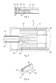
- FIG. 7 shows a side view of a further exemplary embodiment of an endoscope
- FIG. 8 shows a longitudinal section through the endoscope along the line VIII-VIII in FIG. 7 ;
- FIG. 9 shows a perspective illustration of the endoscope in FIG. 7 , without a shaft and without a housing of a headpiece;
- FIG. 10 shows an enlarged illustration of the detail X in FIG. 8 ;
- FIG. 11 shows an enlarged illustration of the detail XI in FIG. 8 ;
- FIG. 12 shows an enlarged illustration of the detail XII in FIG. 8 ;
- FIG. 13 shows an enlarged illustration of the detail XIII in FIG. 9 ;
- FIG. 14 shows an enlarged illustration of the detail XIV in FIG. 9 ;
- FIG. 15 shows an enlarged illustration of the detail XV in FIG. 9 .
- FIG. 1 shows an endoscope, in particular a medical video endoscope, which is provided with the general reference symbol 10 .
- FIGS. 2 to 6 illustrate further details of the endoscope 10 , to which reference will likewise be made in the following text.
- the endoscope 10 generally has an elongated shaft 12 and a headpiece 14 with a housing 16 at a proximal end 18 of the shaft 12 .
- a distal end of the shaft 12 is provided with the reference symbol 20 in FIG. 1 .
- a light source 22 is arranged in a distal area of the shaft 12 which is shown on its own in particular in FIGS. 4 and 6 , and the light source 22 is preferably in the form of a high-power light-emitting diode (LED or OLED).
- the light source 22 produces lost heat during operation.
- the endoscope 10 In order to lead away the lost heat from the light source 22 , in order to prevent the shaft 12 from being heated above the maximum permissible temperature of 41° C. in accordance with the medical product law, particularly in the area of its distal end 20 , the endoscope 10 has a passive cooling, which has a heat pipe 24 arranged in the shaft 12 .
- the heat pipe 24 has a distal end 26 , which is thermally coupled to the light source 22 .
- the thermal coupling is provided via a heat coupling element 28 , which is manufactured as a solid body composed of a highly thermally conductive material, for example copper or aluminium.
- the heat coupling element 28 has an extension 30 in the form of a sleeve, as is illustrated in FIG. 4 , which receives the distal end 26 of the heat pipe 24 without an air gap, in order to ensure that heat is transmitted particularly well from the heat coupling element 28 to the heat pipe 24 .
- the heat coupling element 28 is itself thermally conductively connected over an area to the rear face of the light source 22 .
- the heat pipe 24 extends through the shaft 12 into the headpiece 14 , that is to say it projects into the housing 16 of the headpiece 14 .
- a heat sink body 32 is arranged in the headpiece 14 , and the heat pipe 24 is thermally coupled to it.
- a proximal end 34 of the heat pipe 24 is thermally conductively connected to the heat sink body 32 in an inner sleeve 36 of the heat sink body 32 .
- the heat sink body 32 is itself thermally conductively connected over an area to the housing 16 , such that the heat sink body 32 can transmit the heat absorbed from the heat pipe 24 to the housing 16 of the headpiece 14 , and the heat is then emitted to the environment from the headpiece 14 .
- the heat sink body 32 is tubular or in the form of a rod, and has an external circumference with a large area, with the headpiece 14 likewise having a large area.
- the external diameter of the heat sink body 32 and the external diameter of the housing 16 of the headpiece are greater than the external diameter of the shaft 12 .
- the heat sink body 32 may also itself be part of the housing 16 , and can then emit the absorbed heat directly to the environment.
- the headpiece 14 When the endoscope 10 is being used in a surgical procedure, the headpiece 14 is located outside the human or animal body, as a result of which the heat emitted via the headpiece 14 causes no damage to the environment. In contrast, the outside of the shaft 12 remains below the maximum permissible temperature, at least in the area which is inserted into the human or animal body during the surgical procedure.
- electronic and/or electrical components 40 are arranged in a cavity, which is formed by a sleeve-like extension 38 , in the heat sink body 32 , and their lost heat is likewise transmitted from the heat sink body 32 to the housing 16 .
- the heat pipe 24 is thermally isolated from the inner face of the shaft 12 . This can be achieved by insulating sheathing of the heat pipe 24 itself or by insulation on the inner face of the shaft 12 , as will also be described later with reference to a further exemplary embodiment.
- the endoscope 10 furthermore has a camera 42 which, for example, has a CCD or CMOS-based image sensor 43 , which is arranged in the distal area of the shaft 12 .
- An objective 44 is arranged on the light entrance side in front of the image sensor 43 .
- An electrical line 46 is provided for the light source 22
- an electrical line 48 is provided for the image sensor 43 , and these electrical lines extend from the light source 22 and from the image sensor 43 , respectively, into the headpiece 14 , as is illustrated in FIGS. 2 and 5 .
- the electrical lines 46 and 48 lead to corresponding electrical connections (not illustrated) at the proximal end of the headpiece 14 .
- heat pipe 24 there is a heat pipe 24 provided. Accordingly, there are capillaries and a heat carrier medium in the heat pipe 24 , with the heat carrier medium being vaporized by the lost heat absorbed from the light source 22 at the distal end, and being condensed again at the proximal end 34 of the heat pipe 24 , from where the heat carrier medium passes back again to the distal end by virtue of the capillary effect.
- the heat carrier medium therefore stores heat in the form of latent heat, which is transported proximally, where it is emitted again in the form of latent heat.
- the heat transmission capability of a heat pipe is many times greater than the heat transport capability of, for example, a copper wire.
- an endoscope which is provided with the general reference symbol 50 , will be described in the following text with reference to FIGS. 7 to 15 .
- the endoscope 50 is a medical video endoscope.
- the endoscope 50 has a shaft 52 and a headpiece 54 with a housing 56 .
- the headpiece 54 is arranged at a proximal end 58 of the shaft 52 .
- a distal end of the shaft 52 is provided with the reference symbol 60 .
- a first light source 62 and a second light source 64 are arranged in the distal area of the shaft 52 .
- the light sources 62 and 64 are in the form of LEDs or OLEDs.
- the light sources 62 and 64 produce lost heat during operation, as has already been described in conjunction with the previous exemplary embodiment.
- the endoscope 50 has a first heat pipe 66 , which is thermally coupled to the light sources 62 and 64 , and a further heat pipe 68 , which is thermally coupled to the light sources 62 and 64 .
- a heat coupling element 70 is provided for the thermal coupling between the heat pipes 66 and 68 and the light sources 62 and 64 , into which the distal ends of the heat pipes 66 and 68 are inserted, as far as possible without any air gap, from the proximal side, with the heat coupling element 70 itself being thermally conductively connected to the light sources 62 and 64 .
- the heat coupling element 70 is once again in the form of a solid body, which is manufactured from a highly thermally conductive material, for example copper or aluminium.
- the first heat pipe 66 and the further heat pipe 68 extend into an intermediate area 72 (cf. FIGS. 8, 9 and 11 ), which is located between the distal end 60 and the proximal end 58 of the shaft 52 .
- the intermediate area 72 there is no need for the intermediate area 72 to be located in the centre between the distal end 60 and the proximal end 58 , and, instead, it can also be arranged at points other than those illustrated.
- the first heat pipe 66 and the further heat pipe 68 are thermally coupled to a second heat pipe 74 .
- a further heat coupling element 76 is arranged in the intermediate area 72 for this purpose and is thermally conductively connected both to the proximal ends of the first heat pipe 66 and of the heat pipe 68 , and to the distal end of the second heat pipe 74 .
- the heat coupling element 76 surrounds the proximal ends of the heat pipes 66 and 68 on the one hand, and the distal end of the second heat pipe 74 , on the other hand. This once again ensures good heat transmission from the heat pipes 66 and 68 to the second heat pipe 74 .
- the heat coupling element 76 can itself be designed to be flexible, such that the arrangement, in the form of a cascade, consisting of the heat pipes 66 , 68 on the one hand and the second heat pipe 74 on the other hand is articulated to a certain extent in the intermediate area 72 , thus allowing the shaft 52 of the endoscope 50 also to be designed, in particular, to be semi-flexible.
- the second heat pipe 74 now extends into the headpiece 54 , in which it is thermally coupled to a heat sink body 78 , in which case reference is made with respect to the thermal coupling and the configuration of the heat sink body 78 to the description of the heat sink body 32 in the previous exemplary embodiment, and electronic and/or electrical components can once again be arranged in the heat sink body 78 in this case.
- the endoscope 50 furthermore has a camera 80 , which is arranged in the distal area of the shaft 52 and has, for example, a CCD or CMOS version of an image sensor 81 .
- the camera 80 On the distal side of the image sensor 81 , the camera 80 has an objective 82 .
- the objective 82 has oblique viewing optics 84 , thus allowing the viewing direction of the endoscope 50 to include an angle other than 0°, for example a 30° angle, with the longitudinal axis of the shaft 52 .
- the oblique viewing optics 84 may also be integrated in the objective 82 .
- a rotating drive 86 which is in the form of a magnetic coupling, is correspondingly provided for the camera 80 (image sensor 81 ) on the headpiece 54 .
- the rotating drive 86 has a driving actuating element 88 , which is arranged externally on the shaft 52 at the proximal end 58 , and is in the form of a hand wheel.
- the actuating element 88 has a plurality of magnets 90 on its inner circumference. The magnetic poles are illustrated by N and S in FIG. 12 .
- the rotating drive 86 furthermore has a driven element 92 which interacts magnetically with the actuating element 88 and likewise has a plurality of magnets 94 (cf. FIG. 9 ), whose poles are likewise illustrated by N and S in FIG. 12 . Because of the magnetic force link between the magnets 90 on the actuating element 88 and the magnet 94 on the driven element 92 , the driven element 92 follows a rotational movement of the actuating element 88 in the same rotation direction.
- the second heat pipe 74 is coupled to the driven element 92 , passing through it, in rotationally fixed manner so that rotation of the driven element 92 about its longitudinal axis results in the second heat pipe 74 being rotated in the same rotation direction.
- the second heat pipe 74 is likewise received in the shaft such that it can rotate about its longitudinal axis relative to the shaft 52 .
- the second heat pipe 74 is therefore used not only for heat transport of the lost heat from the light sources 62 and 64 into the headpiece 54 , but also as a torque transmission element for the camera 80 .
- the second heat pipe 74 is surrounded by a tube 96 which, for example, is manufactured from copper or aluminium, or in general from a thermally highly conductive material.
- the second heat pipe 74 is mounted such that it can rotate in the intermediate area 72 in the heat coupling element 76 , while the heat coupling element 76 is itself held such that it cannot rotate, in the same way as the first heat pipe 66 and the second heat pipe 68 , as well as the light sources 62 and 64 .
- the rotatable bearing of the second heat pipe 74 in the heat coupling element 76 is realized such that a good heat transmission from the heat pipes 66 and 68 to the second heat pipe 74 is ensured.
- a proximal end 98 of the second heat pipe 74 is likewise mounted in the headpiece 54 such that it can rotate in the heat sink body 78 .
- a torque transmission element 102 extends distally from a distal end 100 of the second heat pipe 74 and is in this case in the form of a flexible spindle, which is particularly advantageous when the rotation axis of the camera 80 is not aligned with the longitudinal axis of the second heat pipe 74 , as is illustrated in particular in FIG. 8 .
- the torque transmission element 102 is coupled to a distal end 103 of the tube 96 in rotationally fixed manner relative to one another.
- the shaft 52 In order to vary the viewing direction of the endoscope 50 , the shaft 52 is rotated about its longitudinal axis, and in order not to change the orientation of the camera 80 , the actuating element 88 is held fixedly, as a result of which the second heat pipe 74 is likewise held fixedly via the driven element 92 and the camera 80 is held fixedly via the torque transmission element 102 , thus preventing the camera 80 from rotating about its own optical axis, as a result of which the shaft 52 rotates about the camera 80 .
- the shaft 52 is thermally isolated from the heat pipes 66 , 68 and 74 .
- the shaft 52 is provided on the inside with thermal insulation 104 , which is in the form of an intermediate tube composed of a thermally insulated material.
- the thermal insulation 104 in this case extends from the distal end of the shaft 52 to the proximal end of the shaft, part of which projects into the headpiece 54 , as is illustrated in FIGS. 8 and 12 .
- the heat pipes 66 , 68 and 74 may also be sheathed with thermal insulation (not shown) on the outside.
- the endoscope 50 may also have more than the two light sources 62 and 64 and a greater number of heat pipes 66 , 68 , in which case, however, a total of two heat pipes 66 , 68 is advantageous for two light sources 62 and 64 , because the shaft 52 may possibly have a very small diameter.
- the heat pipe cascade comprising the first heat pipe 66 , the further heat pipe 68 and the second heat pipe 74 may also be formed in three, four etc., stages, rather than the two stages as in the present case.
Landscapes
- Health & Medical Sciences (AREA)
- Life Sciences & Earth Sciences (AREA)
- Physics & Mathematics (AREA)
- Surgery (AREA)
- Optics & Photonics (AREA)
- Engineering & Computer Science (AREA)
- Medical Informatics (AREA)
- General Health & Medical Sciences (AREA)
- Pathology (AREA)
- Nuclear Medicine, Radiotherapy & Molecular Imaging (AREA)
- Biomedical Technology (AREA)
- Heart & Thoracic Surgery (AREA)
- Biophysics (AREA)
- Molecular Biology (AREA)
- Animal Behavior & Ethology (AREA)
- Radiology & Medical Imaging (AREA)
- Public Health (AREA)
- Veterinary Medicine (AREA)
- Astronomy & Astrophysics (AREA)
- General Physics & Mathematics (AREA)
- Microelectronics & Electronic Packaging (AREA)
- Multimedia (AREA)
- Endoscopes (AREA)
- Instruments For Viewing The Inside Of Hollow Bodies (AREA)
Abstract
Description
Claims (49)
Applications Claiming Priority (3)
| Application Number | Priority Date | Filing Date | Title |
|---|---|---|---|
| DE102010024003A DE102010024003A1 (en) | 2010-06-11 | 2010-06-11 | endoscope |
| DE102010024003 | 2010-06-11 | ||
| DE102010024003.6 | 2010-06-11 |
Publications (2)
| Publication Number | Publication Date |
|---|---|
| US20110306834A1 US20110306834A1 (en) | 2011-12-15 |
| US9510744B2 true US9510744B2 (en) | 2016-12-06 |
Family
ID=44398260
Family Applications (1)
| Application Number | Title | Priority Date | Filing Date |
|---|---|---|---|
| US13/158,139 Active 2032-06-30 US9510744B2 (en) | 2010-06-11 | 2011-06-10 | Endoscope |
Country Status (3)
| Country | Link |
|---|---|
| US (1) | US9510744B2 (en) |
| EP (1) | EP2394567B8 (en) |
| DE (1) | DE102010024003A1 (en) |
Cited By (4)
| Publication number | Priority date | Publication date | Assignee | Title |
|---|---|---|---|---|
| US10823953B2 (en) | 2017-08-18 | 2020-11-03 | Schölly Fiberoptic GmbH | Video endoscope |
| US11109742B2 (en) | 2017-10-25 | 2021-09-07 | Schölly Fiberoptic GmbH | Magnetic coupling |
| US11737649B2 (en) | 2019-09-05 | 2023-08-29 | Karl Storz Se & Co. Kg | Apparatus for heat dissipation and use of such apparatus |
| US11744449B2 (en) | 2020-03-27 | 2023-09-05 | Altek Biotechnology Corporation | Endoscopy system |
Families Citing this family (35)
| Publication number | Priority date | Publication date | Assignee | Title |
|---|---|---|---|---|
| EP2668892B1 (en) * | 2011-10-27 | 2016-01-06 | Olympus Corporation | Endoscope |
| KR102027251B1 (en) * | 2012-11-22 | 2019-10-01 | 삼성전자주식회사 | Endoscope |
| DE102013001026A1 (en) * | 2013-01-22 | 2014-07-24 | Karl Storz Gmbh & Co. Kg | Endoscopic and / or medical device and cooling device for an endoscope or a medical instrument |
| US20140275763A1 (en) * | 2013-03-15 | 2014-09-18 | Lucent Medical Systems, Inc. | Partially disposable endoscopic device |
| US9814607B2 (en) | 2013-05-07 | 2017-11-14 | The University Of Akron | Low-power method and device for cooling prosthetic limb socket based on phase change |
| CN105358892B (en) * | 2013-06-12 | 2017-04-26 | 建筑机械公司 | Pipe inspection device |
| JP6210764B2 (en) * | 2013-07-10 | 2017-10-11 | オリンパス株式会社 | Electronic endoscope |
| AU2015240552B2 (en) * | 2014-04-04 | 2019-04-04 | Boston Scientific Scimed, Inc. | Medical system and related methods for diagnosis and treatment |
| DE102014107205A1 (en) | 2014-05-22 | 2015-11-26 | Karl Storz Gmbh & Co. Kg | Optical medical instrument, in particular endoscope or exoscope |
| CN105181149B (en) * | 2014-06-20 | 2018-08-21 | 国家电网公司 | A kind of portable all insulation pressure resistance infrared measurement of temperature endoscope |
| US10702137B2 (en) * | 2016-03-14 | 2020-07-07 | Intuitive Surgical Operations, Inc.. | Endoscopic instrument with compliant thermal interface |
| DE102016004664A1 (en) * | 2016-04-18 | 2017-10-19 | Kastriot Merlaku | Drive system for a digital camera of any kind, preferably for a mobile phone digital camera |
| US9927113B2 (en) | 2016-05-26 | 2018-03-27 | Karl Storz Imaging, Inc. | Heat sink structure and LED heat sink assemblies |
| DE102016014247B4 (en) | 2016-11-30 | 2020-10-08 | Karl Storz Se & Co. Kg | Video endoscope and method for operating a video endoscope |
| DE102017105817A1 (en) | 2017-03-17 | 2018-09-20 | First Sensor Lewicki GmbH | Illumination device for attachment in an optical diagnostic device |
| CN110520029A (en) | 2017-05-09 | 2019-11-29 | 直观外科手术操作公司 | For improving the device and method of the heat-sinking capability of medical instrument |
| JP7115493B2 (en) * | 2017-11-01 | 2022-08-09 | ソニーグループ株式会社 | Surgical arm system and surgical arm control system |
| CN108986600B (en) * | 2018-07-17 | 2020-11-03 | 杭州电子科技大学 | A composite thermal diaphragm cooling device for solar telescopes |
| DE102018120696A1 (en) | 2018-08-24 | 2020-02-27 | Karl Storz Se & Co. Kg | Endoscope with a movable component |
| DE102019100147B4 (en) * | 2019-01-04 | 2022-07-28 | Olympus Winter & Ibe Gmbh | video endoscope |
| WO2020185596A1 (en) | 2019-03-11 | 2020-09-17 | Integrated Endoscopy, Inc. | Cordless disposable endoscope |
| DE102019003839A1 (en) | 2019-06-03 | 2020-12-03 | Karl Storz Se & Co. Kg | Endoscope, method for operating an endoscope and method for manufacturing an endoscope |
| DE102019116583A1 (en) * | 2019-06-19 | 2020-12-24 | Karl Storz Se & Co. Kg | Instrument shaft with several channels and its manufacture |
| DE102019004433A1 (en) | 2019-06-22 | 2020-12-24 | Karl Storz Se & Co. Kg | Video endoscope and handle for a video endoscope |
| DE102019212199A1 (en) * | 2019-08-14 | 2021-02-18 | Richard Wolf Gmbh | Light applicator |
| CN110496286B (en) * | 2019-08-21 | 2021-12-14 | 柯纬祺 | Optical rod for trachea cannula |
| EP4093260A4 (en) | 2020-01-24 | 2024-06-05 | Integrated Endoscopy, Inc. | WIRELESS CAMERA SYSTEM FOR ENDOSCOPE |
| US11561387B2 (en) | 2020-03-12 | 2023-01-24 | Integrated Endoscopy, Inc. | Endoscope designs and methods of manufacture |
| CN113448075A (en) * | 2020-03-27 | 2021-09-28 | 荣晶生物科技股份有限公司 | endoscopy system |
| JP2021168841A (en) * | 2020-04-17 | 2021-10-28 | エア・ウォーター株式会社 | Endoscope device and endoscopy system |
| CN111887798B (en) * | 2020-08-31 | 2025-06-17 | 深圳市精锋医疗科技股份有限公司 | Electronic endoscopes and surgical robots |
| TWI843897B (en) * | 2020-09-30 | 2024-06-01 | 模里西斯商鴻建裕醫療投資股份有限公司 | Disposable integrated endoscope |
| WO2024036639A1 (en) * | 2022-08-19 | 2024-02-22 | 武汉迈瑞医疗技术研究院有限公司 | Endoscopic apparatus and system thereof |
| DE102023117345A1 (en) | 2023-06-30 | 2025-01-02 | Karl Storz Se & Co. Kg | endoscope with cooling device |
| WO2025117855A1 (en) * | 2023-11-29 | 2025-06-05 | Resnent, Llc | Modular endoscope assembly |
Citations (18)
| Publication number | Priority date | Publication date | Assignee | Title |
|---|---|---|---|---|
| DE29613103U1 (en) | 1996-06-19 | 1997-10-16 | Wilkens, Jan Henrik, Dr., 66424 Homburg | Endoscope head |
| JPH11299775A (en) * | 1998-04-16 | 1999-11-02 | Hitachi Medical Corp | Ultrasonic diagnostic device |
| WO2004011848A2 (en) | 2002-07-25 | 2004-02-05 | Dahm Jonathan S | Method and apparatus for using light emitting diodes for curing |
| US20060183977A1 (en) * | 2003-10-06 | 2006-08-17 | Olympus Corporation | Endoscope |
| US20060268552A1 (en) | 2005-05-31 | 2006-11-30 | Irion Klaus M | Light source for endoscopy or microscopy |
| EP1738679A2 (en) | 2005-07-01 | 2007-01-03 | Invendo Medical Gmbh | Cooling device for electronic components, particularly for an endoscope |
| JP2007007321A (en) | 2005-07-04 | 2007-01-18 | Olympus Medical Systems Corp | Endoscope |
| JP2007007322A (en) | 2005-07-04 | 2007-01-18 | Olympus Medical Systems Corp | Endoscope |
| JP2007229261A (en) | 2006-03-01 | 2007-09-13 | Fujinon Corp | Endoscope |
| US20080151046A1 (en) | 2006-12-22 | 2008-06-26 | Ge Inspection Technologies, Lp | Heat protection systems and methods for remote viewing devices |
| US20080208297A1 (en) | 2005-01-25 | 2008-08-28 | Allux Medical, Inc. | Optical Therapy Devices, Systems, Kits and Methods for Providing Therapy to a body Cavity |
| US20080208006A1 (en) | 2004-09-24 | 2008-08-28 | Mina Farr | Opto-electronic illumination and vision module for endoscopy |
| JP2009011612A (en) * | 2007-07-05 | 2009-01-22 | Olympus Corp | Endoscope |
| JP2009247620A (en) * | 2008-04-07 | 2009-10-29 | Olympus Corp | Endoscope apparatus and adapter |
| US20100003633A1 (en) | 2008-07-01 | 2010-01-07 | Ivoclar Vivadent Ag | Apparatus for light-curing a dental object |
| US20100087712A1 (en) * | 2008-10-08 | 2010-04-08 | Olympus Corporation | Endoscope |
| DE102009049196A1 (en) | 2009-10-13 | 2010-05-20 | Daimler Ag | Vehicle is provided with heat source, heat sink and heat pipes which are connected with heat source, heat sink and control element |
| EP2311366A1 (en) | 2009-10-19 | 2011-04-20 | Richard Wolf GmbH | LED lighting module |
-
2010
- 2010-06-11 DE DE102010024003A patent/DE102010024003A1/en not_active Withdrawn
-
2011
- 2011-06-09 EP EP11169262.0A patent/EP2394567B8/en active Active
- 2011-06-10 US US13/158,139 patent/US9510744B2/en active Active
Patent Citations (22)
| Publication number | Priority date | Publication date | Assignee | Title |
|---|---|---|---|---|
| DE29613103U1 (en) | 1996-06-19 | 1997-10-16 | Wilkens, Jan Henrik, Dr., 66424 Homburg | Endoscope head |
| JPH11299775A (en) * | 1998-04-16 | 1999-11-02 | Hitachi Medical Corp | Ultrasonic diagnostic device |
| WO2004011848A2 (en) | 2002-07-25 | 2004-02-05 | Dahm Jonathan S | Method and apparatus for using light emitting diodes for curing |
| US20050158687A1 (en) * | 2002-07-25 | 2005-07-21 | Dahm Jonathan S. | Method and apparatus for using light emitting diodes for curing |
| US20060183977A1 (en) * | 2003-10-06 | 2006-08-17 | Olympus Corporation | Endoscope |
| US20080208006A1 (en) | 2004-09-24 | 2008-08-28 | Mina Farr | Opto-electronic illumination and vision module for endoscopy |
| US20080208297A1 (en) | 2005-01-25 | 2008-08-28 | Allux Medical, Inc. | Optical Therapy Devices, Systems, Kits and Methods for Providing Therapy to a body Cavity |
| EP1731862A1 (en) | 2005-05-31 | 2006-12-13 | Karl Storz GmbH & Co. KG | Lightsource for endoscopy or microscopy |
| US20060268552A1 (en) | 2005-05-31 | 2006-11-30 | Irion Klaus M | Light source for endoscopy or microscopy |
| EP1738679A2 (en) | 2005-07-01 | 2007-01-03 | Invendo Medical Gmbh | Cooling device for electronic components, particularly for an endoscope |
| US7914448B2 (en) | 2005-07-01 | 2011-03-29 | invendo medical, GmbH | Cooling means for electronic components preferably of an endoscope |
| JP2007007321A (en) | 2005-07-04 | 2007-01-18 | Olympus Medical Systems Corp | Endoscope |
| JP2007007322A (en) | 2005-07-04 | 2007-01-18 | Olympus Medical Systems Corp | Endoscope |
| JP2007229261A (en) | 2006-03-01 | 2007-09-13 | Fujinon Corp | Endoscope |
| US20080151046A1 (en) | 2006-12-22 | 2008-06-26 | Ge Inspection Technologies, Lp | Heat protection systems and methods for remote viewing devices |
| JP2009011612A (en) * | 2007-07-05 | 2009-01-22 | Olympus Corp | Endoscope |
| JP2009247620A (en) * | 2008-04-07 | 2009-10-29 | Olympus Corp | Endoscope apparatus and adapter |
| US20100003633A1 (en) | 2008-07-01 | 2010-01-07 | Ivoclar Vivadent Ag | Apparatus for light-curing a dental object |
| US20100087712A1 (en) * | 2008-10-08 | 2010-04-08 | Olympus Corporation | Endoscope |
| DE102009049196A1 (en) | 2009-10-13 | 2010-05-20 | Daimler Ag | Vehicle is provided with heat source, heat sink and heat pipes which are connected with heat source, heat sink and control element |
| EP2311366A1 (en) | 2009-10-19 | 2011-04-20 | Richard Wolf GmbH | LED lighting module |
| US20110092772A1 (en) | 2009-10-19 | 2011-04-21 | Richard Wolf Gmbh | Endoscopic instument with an led illumination module |
Non-Patent Citations (1)
| Title |
|---|
| European Search Report; Application No. EP 11 16 9262; Issued: Aug. 29, 2011; Mailing Date: Sep. 5, 2011; 8 pages. |
Cited By (5)
| Publication number | Priority date | Publication date | Assignee | Title |
|---|---|---|---|---|
| US10823953B2 (en) | 2017-08-18 | 2020-11-03 | Schölly Fiberoptic GmbH | Video endoscope |
| US11109742B2 (en) | 2017-10-25 | 2021-09-07 | Schölly Fiberoptic GmbH | Magnetic coupling |
| US11737649B2 (en) | 2019-09-05 | 2023-08-29 | Karl Storz Se & Co. Kg | Apparatus for heat dissipation and use of such apparatus |
| US11957303B2 (en) | 2019-09-05 | 2024-04-16 | Karl Storz Se & Co. Kg | Apparatus for heat dissipation and use of such apparatus |
| US11744449B2 (en) | 2020-03-27 | 2023-09-05 | Altek Biotechnology Corporation | Endoscopy system |
Also Published As
| Publication number | Publication date |
|---|---|
| EP2394567A1 (en) | 2011-12-14 |
| EP2394567B8 (en) | 2018-02-07 |
| US20110306834A1 (en) | 2011-12-15 |
| EP2394567B1 (en) | 2017-12-06 |
| DE102010024003A1 (en) | 2011-12-15 |
Similar Documents
| Publication | Publication Date | Title |
|---|---|---|
| US9510744B2 (en) | Endoscope | |
| US10111577B2 (en) | Endoscopic instrument with an LED illumination module | |
| US10823953B2 (en) | Video endoscope | |
| US9757019B2 (en) | Optical medical instrument | |
| JP5178239B2 (en) | Medical system | |
| US8246230B2 (en) | Disposable attachable light source unit for an endoscope | |
| US20090315986A1 (en) | Endoscope apparatus | |
| US10983332B2 (en) | Device for heat dissipation from an endoscopic illumination apparatus | |
| US20130131451A1 (en) | Medical endoscope with a cooling device for mounted electric components | |
| US9468365B2 (en) | Compact light source | |
| US20220257106A1 (en) | Heat removal infrastructures for endoscopes | |
| JP5927086B2 (en) | Light source device | |
| US11744449B2 (en) | Endoscopy system | |
| JP2010264172A (en) | Cooling device and endoscope apparatus including the same | |
| JP5525987B2 (en) | End of the endoscope | |
| JP2011206159A (en) | Endoscope | |
| JP2007007322A (en) | Endoscope | |
| JPH10178571A (en) | Image pickup device | |
| AU2019265796B2 (en) | Flexible light guide and heat sink for endoscopic systems | |
| JP2007007321A (en) | Endoscope | |
| US8142188B2 (en) | Light curing device/base station combination | |
| JP2009022588A (en) | Illumination device and endoscope provided with the illumination device | |
| JP5509003B2 (en) | Endoscope | |
| US20110224488A1 (en) | Endoscope apparatus | |
| KR102884302B1 (en) | Endoscope having the LED light source |
Legal Events
| Date | Code | Title | Description |
|---|---|---|---|
| AS | Assignment |
Owner name: KARL STORZ GMBH & CO. KG, GERMANY Free format text: ASSIGNMENT OF ASSIGNORS INTEREST;ASSIGNORS:SCHRADER, STEPHEN;OGINSKI, STEFAN;BRUEGGEMANN, DANIEL;SIGNING DATES FROM 20110715 TO 20110719;REEL/FRAME:026744/0936 Owner name: TECHNISCHE UNIVERSITAT BERLIN, GERMANY Free format text: ASSIGNMENT OF ASSIGNORS INTEREST;ASSIGNORS:SCHRADER, STEPHEN;OGINSKI, STEFAN;BRUEGGEMANN, DANIEL;SIGNING DATES FROM 20110715 TO 20110719;REEL/FRAME:026744/0936 |
|
| AS | Assignment |
Owner name: KARL STORZ GMBH & CO. KG, GERMANY Free format text: ASSIGNMENT OF ASSIGNORS INTEREST;ASSIGNOR:TECHNISCHE UNIVERSITAT BERLIN;REEL/FRAME:027169/0940 Effective date: 20110819 |
|
| STCF | Information on status: patent grant |
Free format text: PATENTED CASE |
|
| AS | Assignment |
Owner name: KARL STORZ SE & CO. KG, GERMANY Free format text: CHANGE OF NAME;ASSIGNOR:KARL STORZ GMBH & CO. KG;REEL/FRAME:045373/0627 Effective date: 20170911 |
|
| MAFP | Maintenance fee payment |
Free format text: PAYMENT OF MAINTENANCE FEE, 4TH YEAR, LARGE ENTITY (ORIGINAL EVENT CODE: M1551); ENTITY STATUS OF PATENT OWNER: LARGE ENTITY Year of fee payment: 4 |
|
| MAFP | Maintenance fee payment |
Free format text: PAYMENT OF MAINTENANCE FEE, 8TH YEAR, LARGE ENTITY (ORIGINAL EVENT CODE: M1552); ENTITY STATUS OF PATENT OWNER: LARGE ENTITY Year of fee payment: 8 |