US9507115B2 - Method for determining the edges of an overlapping region between a color filter and a black matrix - Google Patents
Method for determining the edges of an overlapping region between a color filter and a black matrix Download PDFInfo
- Publication number
- US9507115B2 US9507115B2 US14/418,192 US201514418192A US9507115B2 US 9507115 B2 US9507115 B2 US 9507115B2 US 201514418192 A US201514418192 A US 201514418192A US 9507115 B2 US9507115 B2 US 9507115B2
- Authority
- US
- United States
- Prior art keywords
- gray
- overlapping region
- color filter
- black matrix
- area
- Prior art date
- Legal status (The legal status is an assumption and is not a legal conclusion. Google has not performed a legal analysis and makes no representation as to the accuracy of the status listed.)
- Active
Links
- 239000011159 matrix material Substances 0.000 title claims abstract description 100
- 238000000034 method Methods 0.000 title claims abstract description 43
- 238000005259 measurement Methods 0.000 claims abstract description 72
- 239000000758 substrate Substances 0.000 claims description 13
- 238000004519 manufacturing process Methods 0.000 description 4
- 230000008901 benefit Effects 0.000 description 3
- 241001270131 Agaricus moelleri Species 0.000 description 1
- 230000009286 beneficial effect Effects 0.000 description 1
- 239000003086 colorant Substances 0.000 description 1
- 230000003247 decreasing effect Effects 0.000 description 1
- 230000000694 effects Effects 0.000 description 1
- 238000003384 imaging method Methods 0.000 description 1
- 239000010409 thin film Substances 0.000 description 1
Images




Classifications
-
- G—PHYSICS
- G02—OPTICS
- G02B—OPTICAL ELEMENTS, SYSTEMS OR APPARATUS
- G02B7/00—Mountings, adjusting means, or light-tight connections, for optical elements
- G02B7/003—Alignment of optical elements
-
- G—PHYSICS
- G01—MEASURING; TESTING
- G01M—TESTING STATIC OR DYNAMIC BALANCE OF MACHINES OR STRUCTURES; TESTING OF STRUCTURES OR APPARATUS, NOT OTHERWISE PROVIDED FOR
- G01M11/00—Testing of optical apparatus; Testing structures by optical methods not otherwise provided for
-
- G—PHYSICS
- G02—OPTICS
- G02B—OPTICAL ELEMENTS, SYSTEMS OR APPARATUS
- G02B5/00—Optical elements other than lenses
- G02B5/003—Light absorbing elements
-
- G—PHYSICS
- G02—OPTICS
- G02B—OPTICAL ELEMENTS, SYSTEMS OR APPARATUS
- G02B5/00—Optical elements other than lenses
- G02B5/20—Filters
- G02B5/22—Absorbing filters
-
- G—PHYSICS
- G02—OPTICS
- G02F—OPTICAL DEVICES OR ARRANGEMENTS FOR THE CONTROL OF LIGHT BY MODIFICATION OF THE OPTICAL PROPERTIES OF THE MEDIA OF THE ELEMENTS INVOLVED THEREIN; NON-LINEAR OPTICS; FREQUENCY-CHANGING OF LIGHT; OPTICAL LOGIC ELEMENTS; OPTICAL ANALOGUE/DIGITAL CONVERTERS
- G02F1/00—Devices or arrangements for the control of the intensity, colour, phase, polarisation or direction of light arriving from an independent light source, e.g. switching, gating or modulating; Non-linear optics
- G02F1/01—Devices or arrangements for the control of the intensity, colour, phase, polarisation or direction of light arriving from an independent light source, e.g. switching, gating or modulating; Non-linear optics for the control of the intensity, phase, polarisation or colour
- G02F1/13—Devices or arrangements for the control of the intensity, colour, phase, polarisation or direction of light arriving from an independent light source, e.g. switching, gating or modulating; Non-linear optics for the control of the intensity, phase, polarisation or colour based on liquid crystals, e.g. single liquid crystal display cells
- G02F1/1306—Details
- G02F1/1309—Repairing; Testing
-
- G—PHYSICS
- G02—OPTICS
- G02F—OPTICAL DEVICES OR ARRANGEMENTS FOR THE CONTROL OF LIGHT BY MODIFICATION OF THE OPTICAL PROPERTIES OF THE MEDIA OF THE ELEMENTS INVOLVED THEREIN; NON-LINEAR OPTICS; FREQUENCY-CHANGING OF LIGHT; OPTICAL LOGIC ELEMENTS; OPTICAL ANALOGUE/DIGITAL CONVERTERS
- G02F1/00—Devices or arrangements for the control of the intensity, colour, phase, polarisation or direction of light arriving from an independent light source, e.g. switching, gating or modulating; Non-linear optics
- G02F1/01—Devices or arrangements for the control of the intensity, colour, phase, polarisation or direction of light arriving from an independent light source, e.g. switching, gating or modulating; Non-linear optics for the control of the intensity, phase, polarisation or colour
- G02F1/13—Devices or arrangements for the control of the intensity, colour, phase, polarisation or direction of light arriving from an independent light source, e.g. switching, gating or modulating; Non-linear optics for the control of the intensity, phase, polarisation or colour based on liquid crystals, e.g. single liquid crystal display cells
- G02F1/133—Constructional arrangements; Operation of liquid crystal cells; Circuit arrangements
- G02F1/1333—Constructional arrangements; Manufacturing methods
- G02F1/1335—Structural association of cells with optical devices, e.g. polarisers or reflectors
-
- G—PHYSICS
- G09—EDUCATION; CRYPTOGRAPHY; DISPLAY; ADVERTISING; SEALS
- G09G—ARRANGEMENTS OR CIRCUITS FOR CONTROL OF INDICATING DEVICES USING STATIC MEANS TO PRESENT VARIABLE INFORMATION
- G09G3/00—Control arrangements or circuits, of interest only in connection with visual indicators other than cathode-ray tubes
- G09G3/20—Control arrangements or circuits, of interest only in connection with visual indicators other than cathode-ray tubes for presentation of an assembly of a number of characters, e.g. a page, by composing the assembly by combination of individual elements arranged in a matrix no fixed position being assigned to or needed to be assigned to the individual characters or partial characters
- G09G3/2007—Display of intermediate tones
-
- G—PHYSICS
- G02—OPTICS
- G02F—OPTICAL DEVICES OR ARRANGEMENTS FOR THE CONTROL OF LIGHT BY MODIFICATION OF THE OPTICAL PROPERTIES OF THE MEDIA OF THE ELEMENTS INVOLVED THEREIN; NON-LINEAR OPTICS; FREQUENCY-CHANGING OF LIGHT; OPTICAL LOGIC ELEMENTS; OPTICAL ANALOGUE/DIGITAL CONVERTERS
- G02F1/00—Devices or arrangements for the control of the intensity, colour, phase, polarisation or direction of light arriving from an independent light source, e.g. switching, gating or modulating; Non-linear optics
- G02F1/01—Devices or arrangements for the control of the intensity, colour, phase, polarisation or direction of light arriving from an independent light source, e.g. switching, gating or modulating; Non-linear optics for the control of the intensity, phase, polarisation or colour
- G02F1/13—Devices or arrangements for the control of the intensity, colour, phase, polarisation or direction of light arriving from an independent light source, e.g. switching, gating or modulating; Non-linear optics for the control of the intensity, phase, polarisation or colour based on liquid crystals, e.g. single liquid crystal display cells
- G02F1/133—Constructional arrangements; Operation of liquid crystal cells; Circuit arrangements
- G02F1/1333—Constructional arrangements; Manufacturing methods
- G02F1/1335—Structural association of cells with optical devices, e.g. polarisers or reflectors
- G02F1/133509—Filters, e.g. light shielding masks
- G02F1/133512—Light shielding layers, e.g. black matrix
-
- G—PHYSICS
- G02—OPTICS
- G02F—OPTICAL DEVICES OR ARRANGEMENTS FOR THE CONTROL OF LIGHT BY MODIFICATION OF THE OPTICAL PROPERTIES OF THE MEDIA OF THE ELEMENTS INVOLVED THEREIN; NON-LINEAR OPTICS; FREQUENCY-CHANGING OF LIGHT; OPTICAL LOGIC ELEMENTS; OPTICAL ANALOGUE/DIGITAL CONVERTERS
- G02F1/00—Devices or arrangements for the control of the intensity, colour, phase, polarisation or direction of light arriving from an independent light source, e.g. switching, gating or modulating; Non-linear optics
- G02F1/01—Devices or arrangements for the control of the intensity, colour, phase, polarisation or direction of light arriving from an independent light source, e.g. switching, gating or modulating; Non-linear optics for the control of the intensity, phase, polarisation or colour
- G02F1/13—Devices or arrangements for the control of the intensity, colour, phase, polarisation or direction of light arriving from an independent light source, e.g. switching, gating or modulating; Non-linear optics for the control of the intensity, phase, polarisation or colour based on liquid crystals, e.g. single liquid crystal display cells
- G02F1/133—Constructional arrangements; Operation of liquid crystal cells; Circuit arrangements
- G02F1/1333—Constructional arrangements; Manufacturing methods
- G02F1/1335—Structural association of cells with optical devices, e.g. polarisers or reflectors
- G02F1/133509—Filters, e.g. light shielding masks
- G02F1/133514—Colour filters
-
- G—PHYSICS
- G09—EDUCATION; CRYPTOGRAPHY; DISPLAY; ADVERTISING; SEALS
- G09G—ARRANGEMENTS OR CIRCUITS FOR CONTROL OF INDICATING DEVICES USING STATIC MEANS TO PRESENT VARIABLE INFORMATION
- G09G2310/00—Command of the display device
- G09G2310/02—Addressing, scanning or driving the display screen or processing steps related thereto
- G09G2310/0264—Details of driving circuits
- G09G2310/027—Details of drivers for data electrodes, the drivers handling digital grey scale data, e.g. use of D/A converters
Definitions
- the present disclosure relates to the technical field of display, and in particular, to a method for determining edges of an overlapping region between a color filter and a black matrix.
- the size of a color filter and the overlapping region between the color filter and a black matrix should be strictly controlled to avoid light leakage or overlaps between adjacent color filters.
- the overlapping region between a color filter and a black matrix is determined mainly through the difference of gray-scale values at the edges of the color filter and the black matrix. Specifically, the edges of the overlapping region can be determined through the following steps.
- an area to be detected is imaged by a charge-coupled element.
- the area to be detected comprises color filters 1 each having a different color.
- the color filters of different colors in FIG. 1 are filled by different patterns.
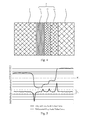
- FIG. 2 shows a magnified version of the measurement area to be detected 9 which are indicated by the dashed box in the area to be detected in FIG. 1 .
- the measurement area to be detected 9 comprises an overlapping region 2 , and a color filter 1 and a black matrix 3 on each side of the overlapping region.
- the gray-scale value is indicated by the density of the filled pattern. The larger the gray-scale value is, the sparser the filled pattern is, and vice versa.
- an original gray-scale value curve is drawn as shown in FIG. 3 based on the variation of the gray-scale value from left to right in the measurement area to be detected 9 , and a differential gray-scale value curve is obtained by calculating the difference of the original gray-scale value curve.
- the overlapping region 2 usually comprises a first overlapping region 21 and a second overlapping region 22 having different gray-scale values. Therefore, as shown in FIG. 3 , the original gray-scale value curve basically comprises four phases, and the corresponding differential gray-scale value curve comprises three distinct extremums.
- An engineer can set an extremum range T d , namely the range between the two double-dot lines as shown in FIG. 3 .
- a detecting device will be able to obtain the three distinct extremums based on the predetermined extremum range T d .
- the overlapping region 2 between the color filter 1 and the black matrix 3 can be determined by the first distinct extremum and the third distinct extremum existing along a direction from left to right.
- the inventor found that, as shown in FIGS. 4 and 5 , if the engineer fails to set an appropriate extremum range, and if the light intensity is low when imaging, there might be four distinct extremums. Obviously, in such a case, the edges of the overlapping region 2 determined by the above method will not be what they actually are.
- the edges of the overlapping region 2 will also shift, which will render the overlapping region 2 wider or narrower.
- the number of the extremums will be increased (five as shown in FIG. 5 ) or decreased (two as shown in FIG. 7 ), in which case, it will be impossible to determine the edges of the overlapping region 2 through the existing method.
- the objective of the present disclosure is to provide a method for determining edges of an overlapping region between a color filter and a black matrix, so as to solve the technical problem that, when the light intensity is inappropriate or the width of the overlapping region changes, the edges of an overlapping region between a color filter and a black matrix cannot be determined accurately.
- the present disclosure provides a method for determining edges of an overlapping region between a color filter and a black matrix, which comprises the following steps.
- a measurement area to be detected is acquired, the measurement area to be detected including a color filter, a black matrix, and an overlapping region therebetween.
- An original gray-scale value curve and a differential gray-scale value curve of the measurement area to be detected are drawn, and extremums of the differential gray-scale value curve are determined based on a predetermined extremum range.
- a gray-scale value of the overlapping region between the color filter and the black matrix is obtained according to gray-scale values of the color filter and the black matrix in the measurement area to be detected and based on a first preset rule.
- a threshold value is established according to the gray-scale values of the color filter, the black matrix, and the overlapping region and based on a second preset rule. According to two intersections of the threshold value and the original gray-scale value curve, two extremums of the differential gray-scale value curve which are the closest to said two intersections respectively are obtained. And then according to the two extremums, the edges of the overlapping region between the color filter and the black matrix are determined.
- the step of obtaining the measurement area to be detected which includes a color filter, a black matrix, and an overlapping region therebetween further comprises the following steps.
- An area to be detected which includes color filters each having a different color is acquired based on a third preset rule. Gray-scale values of the color filters and the black matrix in the area to be detected are obtained.
- a measurement area to be detected which includes a color filter, a black matrix, and an overlapping region therebetween is acquired for each of the color filters each having a different color.
- the method further comprises the following steps.
- a benchmark area on a same color filter substrate is acquired, the benchmark area including color filters each having a different color, and a matching area of the benchmark area is determined.
- Gray-scale values of the color filters each having a different color and the black matrix in the benchmark area are obtained.
- a benchmark measurement area to be detected which includes a color filter, a black matrix, and an overlapping region therebetween is acquired.
- An original gray-scale value curve and a differential gray-scale value curve of the benchmark measurement area are drawn, and an extremum range are set and stored for determining extremums of the differential gray-scale value curve.
- an original threshold value is determined according to the original gray-scale value curve.
- the method further comprises the following steps. Light intensity is adjusted, and under each light intensity, gray-scale values of the color filter, the black matrix, and the overlapping region therebetween in the benchmark measurement area are obtained so as to generate a table of benchmark gray-scale values.
- gray-scale values of a corresponding color filter and a corresponding black matrix are found out from the table of benchmark gray-scale values, and a gray-scale value of a corresponding overlapping region is obtained from the table of benchmark gray-scale values.
- a threshold value is established according to the original threshold value, the gray-scale values of the color filter and the black matrix in the measurement area to be detected, and the gray-scale values of the corresponding color filter, black matrix and overlapping region in the table of benchmark gray-scale values.
- the overlapping region includes a first overlapping region and a second overlapping region having different gray-scale values.
- a threshold value is established according to a smaller one of the gray-scale values of the color filter and the black matrix in the measurement area to be detected, a larger one of the gray-scale values of the corresponding color filter and black matrix in the table of benchmark gray-scale values, and a larger one of obtained gray-scale values of the first overlapping region and the second overlapping region in the overlapping region, based on the original threshold value.
- an area to be detected is acquired according to the matching area and a position thereof in the benchmark area.
- the method further comprises, after determining the edges of the overlapping region between the color filter and the black matrix according to the two extremums, the following steps.
- An original gray-scale value curve is fitted by Gauss curve fitting method or binomial differential method, and a width value of the overlapping region is obtained based on the determined edges of the overlapping region between the color filter and the black matrix.
- the present disclosure achieves the following beneficial effects.
- the technical solutions provided in the embodiments of the present disclosure provide a method for determining edges of an overlapping region between a color filter and a black matrix, which can prevent the situation where, due to an inappropriate light intensity or a shift of color filter substrate in its manufacturing process, the edges of the overlapping region determined are not what they actually are.
- the method is easy to operate, and is helpful in improving the accuracy and stability of determining the overlapping region.
- FIG. 1 schematically shows a measurement area to be detected according to the technical background, or a benchmark area according to the embodiments of the present disclosure
- FIG. 2 schematically shows a larger version 1 of a measurement area according to FIG. 1 ;
- FIG. 3 shows an original gray-scale value curve and a differential gray-scale value curve according to FIG. 2 ;
- FIG. 4 schematically shows a larger version 2 of the measurement area according to FIG. 1 ;
- FIG. 5 shows an original gray-scale value curve and a differential gray-scale value curve according to FIG. 4 ;
- FIG. 6 schematically shows a larger version 3 of the measurement area according to FIG. 1 ;
- FIG. 7 shows an original gray-scale value curve and a differential gray-scale value curve according to FIG. 6 ;
- FIG. 8 schematically shows a flow chart 1 of a method for determining edges of an overlapping region between a color filter and a black matrix according to the embodiments of the present disclosure
- FIG. 9 schematically shows a flow chart 2 of the method for determining the edges of an overlapping region between a color filter and a black matrix according to the embodiments of the present disclosure
- FIG. 10 schematically shows a flow chart 3 of the method for determining the edges of an overlapping region between a color filter and a black matrix according to the embodiments of the present disclosure
- FIG. 11 schematically shows an area to be detected according to the embodiments of the present disclosure
- FIG. 12 shows a larger version of a measurement area according to FIG. 11 ;
- FIG. 13 schematically shows an original gray-scale value curve and a differential gray-scale value curve according to FIG. 12 .
- the present embodiment provides a method for determining edges of an overlapping region between a color filter and a black matrix. As shown in FIG. 8 , the method comprises the following steps.
- step S 101 a measurement area to be detected, which includes a color filter, a black matrix, and an overlapping region therebetween, is acquired.
- step S 102 an original gray-scale value curve and a differential gray-scale value curve of the measurement area to be detected are drawn, and extremums of the differential gray-scale value curve are determined according to a predetermined extremum range.
- step S 103 a gray-scale value of the overlapping region between the color filter and the black matrix is obtained according to the gray-scale values of the color filter and the black matrix in the measurement area to be detected, based on a first preset rule.
- step S 104 a threshold value is established according to the gray-scale values of the color filter, the black matrix, and the overlapping region, based on a second preset rule.
- step S 105 according to two intersections of the threshold value and the original gray-scale value curve, two extremums of the differential gray-scale value curve which are the closest to said two intersections respectively are obtained, and then the edges of the overlapping region between the color filter and the black matrix are determined based on said two extremums.
- the technical solution provided in the present embodiment provides a method for determining edges of an overlapping region between a color filter and a black matrix, which can prevent the situation where, due to an inappropriate light intensity or a shift of color filter substrate in its manufacturing process, the edges of the overlapping region determined are not what they actually are.
- the method is easy to operate, and is helpful in improving the accuracy and stability of determining the overlapping region.
- a benchmark area should be determined first, and some reference values should also be determined based on the benchmark area.
- specific steps are as follows.
- step S 201 a benchmark area on a same color filter substrate is determined, the benchmark area including color filters each having a different color, and then a matching area of the benchmark area is determined.
- the benchmark area is an area selected on the color filter substrate, having an appropriate light intensity, and with overlapping regions 2 which are around each of the color filters 1 having basically a same width.
- the matching area 7 determined in the benchmark area comprises an area on an array substrate which corresponds to a thin film transistor. The determination of the matching area 7 is helpful in acquiring an area to be detected which is similar to the benchmark area, which will facilitate the analysis of the area to be detected based on the benchmark area.
- step S 202 the gray-scale values of the color filters each having a different color and the black matrix in the benchmark area are acquired.
- a gray-scale value reference area 8 is selected from a larger area in each of the color filters 1 and the black matrix 2 , and an average gray-scale value of the gray-scale value reference area 8 defaults to a gray-scale value of a corresponding color filter 1 or a corresponding black matrix 2 .
- the gray-scale value reference area 8 is usually located near the center of the larger area in the color filter 1 or in the black matrix 3 .
- step S 203 for each of the color filters each having a different color, a benchmark measurement area is acquired, the benchmark measurement area including a color filter, a black matrix, and an overlapping region therebetween.
- the benchmark measurement area 9 acquired from FIG. 1 is as shown in FIG. 2 .
- step S 204 an original gray-scale value curve and a differential gray-scale value curve of the benchmark measurement area are drawn, and an extremum range is set for determining extremums of the differential gray-scale value curve.
- an original gray-scale value curve and a differential gray-scale value curve can be drawn according to the distribution of the gray-scale value of the benchmark measurement area 9 .
- the original gray-scale value curve can be divided into phase a, phase b, phase c, and phase d according to the four phases thereof, and G a , G b , G c , and G d are used to indicate the gray-scale values of the four phases respectively.
- an extremum range T d is needed.
- the determination of the extremum range should be based on the distribution the differential gray-scale value curve, ensuring that the extremum range T d , on the one hand, covers those less distinct extremums, and on the other, excludes those distinct extremums.
- the differential gray-scale value curve moves mostly around a line indicating a gray-scale value of zero, and thus only several extremums (three in FIG. 3 ) are obviously larger or smaller than zero. Therefore, the extremum range T d can be set to be a range between two values located symmetrically around the line indicating the gray-scale value of zero, such as ⁇ 10, ⁇ 30, etc.
- step S 205 an original threshold value is determined according to the original gray-scale value curve.
- the original threshold value T S should enable the four phases of the original gray-scale value curve to be distributed evenly at two sides of the original threshold value T S . That is, phase a and phase d having larger gray-scale values are located above the original threshold value T S , and phase b and phase c having smaller gray-scale values are located below the original threshold value T S .
- the original threshold value T S should be: MAX (G b , G c ) ⁇ T S ⁇ MIN (G a , G d ).
- a table of benchmark gray-scale values should be established for use in analyzing the area to be detected.
- Specific steps for establishing the table of benchmark gray-scale values are: adjusting light intensity, and obtaining gray-scale values of the color filter 1 , the black matrix 3 , and the overlapping region 2 therebetween in the benchmark measurement area under each light intensity; and generating and storing a table of benchmark gray-scale values.
- the benchmark measurement area 9 as shown in FIG.
- the light intensity is increased gradually from zero, and for each increment of light intensity, four average gray-scale values of the four areas, namely a black matrix 3 , a first overlapping region 21 , a first overlapping region 22 , as well as a color filter 1 in the benchmark measurement area 9 , which are respectively expressed by G a1 , G b1 , G c1 , and G d1 , are recorded, until the gray-scale value of one of the four areas reaches saturation (for CCD with a 8 bit gray-scale value, the saturation gray-scale value is 255).
- a color filter substrate it is irradiated by a 100 W light source, and the light intensity is increased by 1 W each time.
- the average gray-scale value of a color filter 1 in a benchmark measurement area 9 reaches 255.
- a table of benchmark gray-scale values as follows can be obtained.
- the gray-scale value of the color filter 1 increases distinctly as the light intensity is increased.
- the first step thereof is to acquire a measurement area to be detected 9 , which is shown in FIG. 10 and comprises the following steps.
- step S 301 based on a third preset rule, an area to be detected, which includes color filters each having a different color, is acquired.
- an area to be detected is acquired according to the matching area 7 and the position thereof in the benchmark area.
- the acquired area to be detected has a matching area 7 which matches the matching area 7 in the benchmark area with a matching degree being larger than a preset value (e.g., 95%), and the position of the matching area 7 in the area to be detected is the same as that of the matching area 7 in the benchmark area.
- the area to be detected can be analyzed effectively, and the edges of the overlapping region 2 between the color filter 1 and a black matrix 3 can be determined.
- the acquired area to be detected has structures and shapes similar to the benchmark area, and comprises color filters 1 each having a different color.
- the light intensity is lower when the area to be detected is acquired than when the benchmark area is acquired. Therefore, by comparing FIG. 11 with FIG. 1 , it can be judged from the density of the filled pattern that the gray-scale value of the color filter 1 in the area to be detected is smaller than that of the color filter 1 in the benchmark area.
- step S 302 the gray-scale values of the color filters and the black matrix in the area to be detected are obtained.
- a gray-scale value reference area 8 is selected from a larger area in each of the color filters 1 and the black matrix 3 .
- An average gray-scale value of the gray-scale value reference area 8 is used to indicate a gray-scale value of the color filter 1 or the black matrix 2 .
- step S 303 for each of the color filters each having a different color, said measurement area to be detected, which includes a color filter, a black matrix, and an overlapping region therebetween, is acquired.
- a measurement area to be detected 9 of a color filter is acquired from the area to be detected as shown in FIG. 11 .
- the gray-scale value of the color filter 1 in the benchmark measurement area 9 is larger than that of the color filter 1 in the measurement area to be detected 9 , and the gray-scale value of each of other areas remains almost the same.
- the differential gray-scale value curve of the measurement area to be detected has three extremums.
- a gray-scale value of the overlapping region 2 between the color filter 1 and the black matrix 3 is obtained.
- gray-scale values of a corresponding color filter 1 and a corresponding black matrix 3 are found out from the table of benchmark gray-scale values based on the gray-scales value of the color filter 1 and the black matrix 3 in the measurement area to be detected 9 , and then a gray-scale value of the overlapping region 2 is obtained from the table of benchmark gray-scale values.
- the gray-scale values of the color filter 1 and the black matrix 3 that are equal to or closest to each other are found out from the table of benchmark gray-scale values.
- the gray-scale values of the color filter 1 and the black matrix are respectively 91 and 142
- the table of benchmark gray-scale values it can be obtained that the gray-scale values of the first overlapping region 21 and the second overlapping region 22 of the overlapping region 2 are respectively 36 and 78 .
- a threshold value T′ S can be established based on a second preset rule.
- the threshold value T′ S is established based on the original threshold value T S , the gray-scale values of the color filter 1 and the black matrix 3 in the measurement area to be detected 9 , and the gray-scale values of the corresponding color filter 1 , black matrix 3 , and overlapping region 2 in the table of benchmark gray-scale values.
- the obtained overlapping region 2 in the benchmark measurement area 9 comprises a first overlapping region 21 and a second overlapping region 22 having different gray-scale values.
- the acquired measurement area to be detected 9 also comprises a first overlapping region 21 and a second overlapping region 22 having different gray-scale values.
- the threshold value T′ S is established based on a smaller one of the gray-scale values of the color filter 1 and the black matrix 3 in the measurement area to be detected 9 , a larger one of the gray-scale values of the corresponding color filter 1 and the corresponding black matrix 3 in the table of benchmark gray-scale values, and a larger one of the obtained gray-scale values of the first overlapping region 21 and the second overlapping region 22 of the overlapping region 22 , and also based on the original threshold value T S . That is, the threshold value T′ S is established based on the following formula:
- T S ′ ( t 2 - t 1 t 3 - t 1 ) * T S + t 1 * ( t 2 - t 3 t 3 - t 1 ) .
- t 1 MAX (G b , G c )
- t 2 MIN (G′ a , G′ d )
- t 3 MAX (G a , G d )
- G′ a and G′ b refer to the gray-scale values of the color filter 1 and the black matrix 3 in the measurement area to be detected 9 respectively.
- the threshold value T′ S (as shown by the dot double-line) is smaller than the original threshold value T S (as shown by the dot line).
- the two extremums on the differential gray-scale value curve being closest to the two intersections are the leftmost extremum and the rightmost extremum respectively.
- each extremum of the differential gray-scale value curve exactly corresponds to an edge of an area of the measurement area to be detected 9 .
- the edges of the overlapping region 2 between the color filter 1 and the black matrix 3 can be obtained based on the two extremums.
- the method for determining the edges of the overlapping region 2 also apply to the situations where the light intensity is inappropriate or the width of the overlapping region varies, and consequently the number of the extremums obtained based on the extremum range T d is not three.
- the measurement area to be detected 9 might comprises five areas according to the gray-scale values, and the overlapping region 2 comprises a first overlapping region 21 , a second overlapping region 22 , and a third overlapping region 23 having different gray-scale values. Accordingly, as shown in FIG.
- the original gray-scale value curve corresponding to the measurement area to be detected 9 comprises five phases, and has four distinct extremums based on the obtained differential gray-scale value curve and the extremum range T d .
- intersections of the threshold value T′ S and the original gray-scale value curve are obtained based on the established threshold value T′ S , and the two extremums closest to said two intersections are the leftmost extremum and the rightmost extremum respectively.
- the edges of the overlapping region 2 between the color filter 1 and the black matrix 3 can be obtained based on the two extremums.
- the measurement to be detected 9 might comprise only three areas based on the gray-scale values, and there is no obvious difference in the overlapping region 2 .
- the original gray-scale value curve corresponding to the measurement area to be detected 9 comprises three phases, and has merely two distinct extremums based on the obtained differential gray-scale value curve and the extremum range.
- intersections of the threshold value T′ S and the original gray-scale value curve are obtained based on the established threshold value T′ S , and the two extremums closest to the two intersections are the leftmost extremum and the rightmost extremum respectively.
- the edges of the overlapping region 2 between the color filter 1 and the black matrix 3 can be obtained based on the two extremums.
- the leftmost extremum corresponds to the edges of the black matrix 3 .
- the color filter 1 on the right side of the rightmost extremum is the color filter 1 , and on the left side thereof is the overlapping region 2 , and therefore, the rightmost extremum corresponds to the edges of the color filter 1 .
- the method for determining the edges of the overlapping region provided in the present disclosure is to determine the edges of the black matrix 3 and the color filter 1 first, and then obtain the edges of the overlapping region 2 .
- an original gray-scale value curve can be fitted by Gauss curve fitting method or binomial differential method, and based on the determined edges of the overlapping region 2 between the color filter 1 and the black matrix 3 , the position of the edges under sub-pixel precision is obtained, thereby obtaining a width value of the overlapping region 2 .
- FIG. 1 or FIG. 11 comprises only one measurement area 9 .
- the widths of the overlapping region 2 around the color filter 1 are not necessarily the same. In practice, to better know the widths of the overlapping regions 2 each around the color filter 1 , it is necessary to acquire at least one measurement area 9 from each edge of the color filter 1 , which will not be described in detail in the present embodiment.
Landscapes
- Physics & Mathematics (AREA)
- General Physics & Mathematics (AREA)
- Optics & Photonics (AREA)
- Nonlinear Science (AREA)
- Chemical & Material Sciences (AREA)
- Crystallography & Structural Chemistry (AREA)
- Engineering & Computer Science (AREA)
- Mathematical Physics (AREA)
- Analytical Chemistry (AREA)
- Computer Hardware Design (AREA)
- Theoretical Computer Science (AREA)
- Image Analysis (AREA)
- Facsimile Image Signal Circuits (AREA)
- Color Image Communication Systems (AREA)
Applications Claiming Priority (4)
| Application Number | Priority Date | Filing Date | Title |
|---|---|---|---|
| CN201410837283.5 | 2014-12-26 | ||
| CN201410837283 | 2014-12-26 | ||
| CN201410837283.5A CN104460104B (zh) | 2014-12-26 | 2014-12-26 | 确定彩色滤色块与黑矩阵的交叠区域的边缘的方法 |
| PCT/CN2015/071234 WO2016101376A1 (zh) | 2014-12-26 | 2015-01-21 | 确定彩色滤色块与黑矩阵的交叠区域的边缘的方法 |
Publications (2)
| Publication Number | Publication Date |
|---|---|
| US20160246026A1 US20160246026A1 (en) | 2016-08-25 |
| US9507115B2 true US9507115B2 (en) | 2016-11-29 |
Family
ID=52906402
Family Applications (1)
| Application Number | Title | Priority Date | Filing Date |
|---|---|---|---|
| US14/418,192 Active US9507115B2 (en) | 2014-12-26 | 2015-01-21 | Method for determining the edges of an overlapping region between a color filter and a black matrix |
Country Status (3)
| Country | Link |
|---|---|
| US (1) | US9507115B2 (zh) |
| CN (1) | CN104460104B (zh) |
| WO (1) | WO2016101376A1 (zh) |
Families Citing this family (4)
| Publication number | Priority date | Publication date | Assignee | Title |
|---|---|---|---|---|
| CN107678200B (zh) * | 2017-10-26 | 2021-03-30 | 惠科股份有限公司 | 显示面板 |
| CN110517318B (zh) * | 2019-08-28 | 2022-05-17 | 昆山国显光电有限公司 | 定位方法和装置、存储介质 |
| CN116399869A (zh) * | 2021-12-27 | 2023-07-07 | 致茂电子(苏州)有限公司 | 用于助焊剂检测的照射光调整方法及使用该方法的检测设备 |
| CN114815256B (zh) * | 2022-04-15 | 2023-10-03 | 青岛虚拟现实研究院有限公司 | 虚拟现实头戴设备的屏幕参数调整方法、设备、存储介质 |
Citations (7)
| Publication number | Priority date | Publication date | Assignee | Title |
|---|---|---|---|---|
| US20060055985A1 (en) * | 2004-09-13 | 2006-03-16 | Canon Kabushiki Kaisha | Color-noise reduction circuit and image-sensing apparatus therewith |
| JP2010097109A (ja) | 2008-10-20 | 2010-04-30 | Toppan Printing Co Ltd | カラーフィルタ検査方法 |
| JP2011257262A (ja) | 2010-06-09 | 2011-12-22 | Toppan Printing Co Ltd | カラーフィルタ基板のムラ検査装置 |
| CN102520537A (zh) | 2011-12-02 | 2012-06-27 | 深圳市华星光电技术有限公司 | 一种自动光学检测方法和光学自动检测设备 |
| CN102854195A (zh) | 2012-09-21 | 2013-01-02 | 京东方科技集团股份有限公司 | 彩色滤光片上缺陷坐标的检测方法 |
| CN103033343A (zh) | 2012-12-13 | 2013-04-10 | 京东方科技集团股份有限公司 | 检测彩色滤光片中亚像素偏移的方法及装置 |
| CN103759644A (zh) | 2014-01-23 | 2014-04-30 | 广州市光机电技术研究院 | 一种滤光片表面缺陷的分离细化智能检测方法 |
Family Cites Families (1)
| Publication number | Priority date | Publication date | Assignee | Title |
|---|---|---|---|---|
| JP2009175556A (ja) * | 2008-01-25 | 2009-08-06 | Fujifilm Corp | カラーフィルタ及びその製造方法、ならびに液晶表示装置 |
-
2014
- 2014-12-26 CN CN201410837283.5A patent/CN104460104B/zh active Active
-
2015
- 2015-01-21 US US14/418,192 patent/US9507115B2/en active Active
- 2015-01-21 WO PCT/CN2015/071234 patent/WO2016101376A1/zh not_active Ceased
Patent Citations (7)
| Publication number | Priority date | Publication date | Assignee | Title |
|---|---|---|---|---|
| US20060055985A1 (en) * | 2004-09-13 | 2006-03-16 | Canon Kabushiki Kaisha | Color-noise reduction circuit and image-sensing apparatus therewith |
| JP2010097109A (ja) | 2008-10-20 | 2010-04-30 | Toppan Printing Co Ltd | カラーフィルタ検査方法 |
| JP2011257262A (ja) | 2010-06-09 | 2011-12-22 | Toppan Printing Co Ltd | カラーフィルタ基板のムラ検査装置 |
| CN102520537A (zh) | 2011-12-02 | 2012-06-27 | 深圳市华星光电技术有限公司 | 一种自动光学检测方法和光学自动检测设备 |
| CN102854195A (zh) | 2012-09-21 | 2013-01-02 | 京东方科技集团股份有限公司 | 彩色滤光片上缺陷坐标的检测方法 |
| CN103033343A (zh) | 2012-12-13 | 2013-04-10 | 京东方科技集团股份有限公司 | 检测彩色滤光片中亚像素偏移的方法及装置 |
| CN103759644A (zh) | 2014-01-23 | 2014-04-30 | 广州市光机电技术研究院 | 一种滤光片表面缺陷的分离细化智能检测方法 |
Non-Patent Citations (1)
| Title |
|---|
| International Search Report and Written Opinion, Jan. 21, 2015, China. |
Also Published As
| Publication number | Publication date |
|---|---|
| CN104460104A (zh) | 2015-03-25 |
| US20160246026A1 (en) | 2016-08-25 |
| CN104460104B (zh) | 2017-07-21 |
| WO2016101376A1 (zh) | 2016-06-30 |
Similar Documents
| Publication | Publication Date | Title |
|---|---|---|
| US9507115B2 (en) | Method for determining the edges of an overlapping region between a color filter and a black matrix | |
| US9134615B2 (en) | Exposure method for glass substrate of liquid crystal display | |
| US9646370B2 (en) | Automatic detection method for defects of a display panel | |
| US8743214B2 (en) | Display screen for camera calibration | |
| US20180211368A1 (en) | Method and device for adjusting contrast | |
| CN105069453B (zh) | 一种图像校正方法及装置 | |
| CN204229078U (zh) | 摩尔纹调试装置 | |
| CN107516325A (zh) | 基于亚像素边缘的圆心检测方法 | |
| US11322100B2 (en) | Gray scale setting method, display substrate and display apparatus | |
| US20210325299A1 (en) | Digital assessment of chemical dip tests | |
| CN104853180B (zh) | 图像获取系统的校正方法 | |
| CN104732207A (zh) | 高精度与高抗干扰性定位PCB板Mark点的方法及装置 | |
| CN108961345B (zh) | 一种尿液试纸中有效颜色的确定方法及确定装置 | |
| US20170162090A1 (en) | Device and method for testing transparency effect of transparent display substrate | |
| CN108022219B (zh) | 一种二维图像灰度修正方法 | |
| CN111179184B (zh) | 基于随机抽样一致性的鱼眼图像有效区域提取方法 | |
| WO2016026238A1 (zh) | 图像的边界判别方法、装置和显示面板 | |
| US20090220151A1 (en) | Device for adjusting image color difference value and adjusting method thereof | |
| CN104298844A (zh) | 获取点阵法测量光学遥感载荷在轨mtf测量精度的方法 | |
| WO2018076591A1 (zh) | 用于设备的方法、制造掩膜版或显示基板的方法及系统 | |
| JP6390248B2 (ja) | 情報処理装置、ぼけ具合計算方法、及びプログラム | |
| US8947649B2 (en) | Apparatus and method for determining optical center in camera module | |
| CN103713471B (zh) | 一种关键尺寸测试的校正装置和方法 | |
| WO2017080295A1 (zh) | 元件的定位方法和系统 | |
| US10204407B2 (en) | Measurement method and measurement device of critical dimension of sub-pixel |
Legal Events
| Date | Code | Title | Description |
|---|---|---|---|
| AS | Assignment |
Owner name: SHENZHEN CHINA STAR OPTOELECTRONICS TECHNOLOGY CO. Free format text: ASSIGNMENT OF ASSIGNORS INTEREST;ASSIGNORS:SHI, KAI;CHEN, LINDOU;REEL/FRAME:036383/0246 Effective date: 20150320 |
|
| STCF | Information on status: patent grant |
Free format text: PATENTED CASE |
|
| MAFP | Maintenance fee payment |
Free format text: PAYMENT OF MAINTENANCE FEE, 4TH YEAR, LARGE ENTITY (ORIGINAL EVENT CODE: M1551); ENTITY STATUS OF PATENT OWNER: LARGE ENTITY Year of fee payment: 4 |
|
| MAFP | Maintenance fee payment |
Free format text: PAYMENT OF MAINTENANCE FEE, 8TH YEAR, LARGE ENTITY (ORIGINAL EVENT CODE: M1552); ENTITY STATUS OF PATENT OWNER: LARGE ENTITY Year of fee payment: 8 |