US9502796B2 - Plug connector for differential data transmission - Google Patents
Plug connector for differential data transmission Download PDFInfo
- Publication number
- US9502796B2 US9502796B2 US13/816,837 US201113816837A US9502796B2 US 9502796 B2 US9502796 B2 US 9502796B2 US 201113816837 A US201113816837 A US 201113816837A US 9502796 B2 US9502796 B2 US 9502796B2
- Authority
- US
- United States
- Prior art keywords
- plug
- contact carrier
- electric contacts
- connector
- connector according
- Prior art date
- Legal status (The legal status is an assumption and is not a legal conclusion. Google has not performed a legal analysis and makes no representation as to the accuracy of the status listed.)
- Active
Links
- 230000005540 biological transmission Effects 0.000 title claims description 6
- 230000015572 biosynthetic process Effects 0.000 claims description 14
- 238000005755 formation reaction Methods 0.000 claims description 14
- 238000002347 injection Methods 0.000 claims description 5
- 239000007924 injection Substances 0.000 claims description 5
- 239000012777 electrically insulating material Substances 0.000 claims description 2
- 238000010276 construction Methods 0.000 claims 2
- 230000037431 insertion Effects 0.000 claims 2
- 238000003780 insertion Methods 0.000 claims 2
- 239000000463 material Substances 0.000 claims 2
- 239000011324 bead Substances 0.000 description 3
- 238000009413 insulation Methods 0.000 description 2
- 238000012986 modification Methods 0.000 description 2
- 230000004048 modification Effects 0.000 description 2
- 230000010287 polarization Effects 0.000 description 2
- 230000008054 signal transmission Effects 0.000 description 2
- 125000006850 spacer group Chemical group 0.000 description 2
- 239000000969 carrier Substances 0.000 description 1
- 239000004020 conductor Substances 0.000 description 1
- 230000000694 effects Effects 0.000 description 1
- 238000005516 engineering process Methods 0.000 description 1
- 239000011796 hollow space material Substances 0.000 description 1
- 238000001746 injection moulding Methods 0.000 description 1
- 239000011810 insulating material Substances 0.000 description 1
- 230000002452 interceptive effect Effects 0.000 description 1
- 239000012811 non-conductive material Substances 0.000 description 1
- 230000002093 peripheral effect Effects 0.000 description 1
- 230000001681 protective effect Effects 0.000 description 1
- 230000005855 radiation Effects 0.000 description 1
- 238000005476 soldering Methods 0.000 description 1
Images


Classifications
-
- H—ELECTRICITY
- H01—ELECTRIC ELEMENTS
- H01R—ELECTRICALLY-CONDUCTIVE CONNECTIONS; STRUCTURAL ASSOCIATIONS OF A PLURALITY OF MUTUALLY-INSULATED ELECTRICAL CONNECTING ELEMENTS; COUPLING DEVICES; CURRENT COLLECTORS
- H01R12/00—Structural associations of a plurality of mutually-insulated electrical connecting elements, specially adapted for printed circuits, e.g. printed circuit boards [PCB], flat or ribbon cables, or like generally planar structures, e.g. terminal strips, terminal blocks; Coupling devices specially adapted for printed circuits, flat or ribbon cables, or like generally planar structures; Terminals specially adapted for contact with, or insertion into, printed circuits, flat or ribbon cables, or like generally planar structures
- H01R12/70—Coupling devices
- H01R12/71—Coupling devices for rigid printing circuits or like structures
- H01R12/72—Coupling devices for rigid printing circuits or like structures coupling with the edge of the rigid printed circuits or like structures
- H01R12/722—Coupling devices for rigid printing circuits or like structures coupling with the edge of the rigid printed circuits or like structures coupling devices mounted on the edge of the printed circuits
- H01R12/724—Coupling devices for rigid printing circuits or like structures coupling with the edge of the rigid printed circuits or like structures coupling devices mounted on the edge of the printed circuits containing contact members forming a right angle
-
- H—ELECTRICITY
- H01—ELECTRIC ELEMENTS
- H01R—ELECTRICALLY-CONDUCTIVE CONNECTIONS; STRUCTURAL ASSOCIATIONS OF A PLURALITY OF MUTUALLY-INSULATED ELECTRICAL CONNECTING ELEMENTS; COUPLING DEVICES; CURRENT COLLECTORS
- H01R13/00—Details of coupling devices of the kinds covered by groups H01R12/70 or H01R24/00 - H01R33/00
- H01R13/46—Bases; Cases
- H01R13/502—Bases; Cases composed of different pieces
- H01R13/504—Bases; Cases composed of different pieces different pieces being moulded, cemented, welded, e.g. ultrasonic, or swaged together
-
- H—ELECTRICITY
- H01—ELECTRIC ELEMENTS
- H01R—ELECTRICALLY-CONDUCTIVE CONNECTIONS; STRUCTURAL ASSOCIATIONS OF A PLURALITY OF MUTUALLY-INSULATED ELECTRICAL CONNECTING ELEMENTS; COUPLING DEVICES; CURRENT COLLECTORS
- H01R13/00—Details of coupling devices of the kinds covered by groups H01R12/70 or H01R24/00 - H01R33/00
- H01R13/646—Details of coupling devices of the kinds covered by groups H01R12/70 or H01R24/00 - H01R33/00 specially adapted for high-frequency, e.g. structures providing an impedance match or phase match
- H01R13/6461—Means for preventing cross-talk
- H01R13/6471—Means for preventing cross-talk by special arrangement of ground and signal conductors, e.g. GSGS [Ground-Signal-Ground-Signal]
-
- H—ELECTRICITY
- H01—ELECTRIC ELEMENTS
- H01R—ELECTRICALLY-CONDUCTIVE CONNECTIONS; STRUCTURAL ASSOCIATIONS OF A PLURALITY OF MUTUALLY-INSULATED ELECTRICAL CONNECTING ELEMENTS; COUPLING DEVICES; CURRENT COLLECTORS
- H01R13/00—Details of coupling devices of the kinds covered by groups H01R12/70 or H01R24/00 - H01R33/00
- H01R13/648—Protective earth or shield arrangements on coupling devices, e.g. anti-static shielding
- H01R13/658—High frequency shielding arrangements, e.g. against EMI [Electro-Magnetic Interference] or EMP [Electro-Magnetic Pulse]
- H01R13/6581—Shield structure
- H01R13/6585—Shielding material individually surrounding or interposed between mutually spaced contacts
-
- H—ELECTRICITY
- H01—ELECTRIC ELEMENTS
- H01R—ELECTRICALLY-CONDUCTIVE CONNECTIONS; STRUCTURAL ASSOCIATIONS OF A PLURALITY OF MUTUALLY-INSULATED ELECTRICAL CONNECTING ELEMENTS; COUPLING DEVICES; CURRENT COLLECTORS
- H01R13/00—Details of coupling devices of the kinds covered by groups H01R12/70 or H01R24/00 - H01R33/00
- H01R13/46—Bases; Cases
- H01R13/50—Bases; Cases formed as an integral body
- H01R13/501—Bases; Cases formed as an integral body comprising an integral hinge or a frangible part
-
- H—ELECTRICITY
- H01—ELECTRIC ELEMENTS
- H01R—ELECTRICALLY-CONDUCTIVE CONNECTIONS; STRUCTURAL ASSOCIATIONS OF A PLURALITY OF MUTUALLY-INSULATED ELECTRICAL CONNECTING ELEMENTS; COUPLING DEVICES; CURRENT COLLECTORS
- H01R13/00—Details of coupling devices of the kinds covered by groups H01R12/70 or H01R24/00 - H01R33/00
- H01R13/46—Bases; Cases
- H01R13/502—Bases; Cases composed of different pieces
- H01R13/506—Bases; Cases composed of different pieces assembled by snap action of the parts
-
- H—ELECTRICITY
- H01—ELECTRIC ELEMENTS
- H01R—ELECTRICALLY-CONDUCTIVE CONNECTIONS; STRUCTURAL ASSOCIATIONS OF A PLURALITY OF MUTUALLY-INSULATED ELECTRICAL CONNECTING ELEMENTS; COUPLING DEVICES; CURRENT COLLECTORS
- H01R13/00—Details of coupling devices of the kinds covered by groups H01R12/70 or H01R24/00 - H01R33/00
- H01R13/62—Means for facilitating engagement or disengagement of coupling parts or for holding them in engagement
- H01R13/629—Additional means for facilitating engagement or disengagement of coupling parts, e.g. aligning or guiding means, levers, gas pressure electrical locking indicators, manufacturing tolerances
- H01R13/631—Additional means for facilitating engagement or disengagement of coupling parts, e.g. aligning or guiding means, levers, gas pressure electrical locking indicators, manufacturing tolerances for engagement only
- H01R13/6315—Additional means for facilitating engagement or disengagement of coupling parts, e.g. aligning or guiding means, levers, gas pressure electrical locking indicators, manufacturing tolerances for engagement only allowing relative movement between coupling parts, e.g. floating connection
-
- H—ELECTRICITY
- H01—ELECTRIC ELEMENTS
- H01R—ELECTRICALLY-CONDUCTIVE CONNECTIONS; STRUCTURAL ASSOCIATIONS OF A PLURALITY OF MUTUALLY-INSULATED ELECTRICAL CONNECTING ELEMENTS; COUPLING DEVICES; CURRENT COLLECTORS
- H01R13/00—Details of coupling devices of the kinds covered by groups H01R12/70 or H01R24/00 - H01R33/00
- H01R13/648—Protective earth or shield arrangements on coupling devices, e.g. anti-static shielding
- H01R13/658—High frequency shielding arrangements, e.g. against EMI [Electro-Magnetic Interference] or EMP [Electro-Magnetic Pulse]
- H01R13/6581—Shield structure
- H01R13/6582—Shield structure with resilient means for engaging mating connector
- H01R13/6583—Shield structure with resilient means for engaging mating connector with separate conductive resilient members between mating shield members
-
- H—ELECTRICITY
- H01—ELECTRIC ELEMENTS
- H01R—ELECTRICALLY-CONDUCTIVE CONNECTIONS; STRUCTURAL ASSOCIATIONS OF A PLURALITY OF MUTUALLY-INSULATED ELECTRICAL CONNECTING ELEMENTS; COUPLING DEVICES; CURRENT COLLECTORS
- H01R13/00—Details of coupling devices of the kinds covered by groups H01R12/70 or H01R24/00 - H01R33/00
- H01R13/648—Protective earth or shield arrangements on coupling devices, e.g. anti-static shielding
- H01R13/658—High frequency shielding arrangements, e.g. against EMI [Electro-Magnetic Interference] or EMP [Electro-Magnetic Pulse]
- H01R13/6581—Shield structure
- H01R13/6585—Shielding material individually surrounding or interposed between mutually spaced contacts
- H01R13/6586—Shielding material individually surrounding or interposed between mutually spaced contacts for separating multiple connector modules
- H01R13/6587—Shielding material individually surrounding or interposed between mutually spaced contacts for separating multiple connector modules for mounting on PCBs
-
- H—ELECTRICITY
- H01—ELECTRIC ELEMENTS
- H01R—ELECTRICALLY-CONDUCTIVE CONNECTIONS; STRUCTURAL ASSOCIATIONS OF A PLURALITY OF MUTUALLY-INSULATED ELECTRICAL CONNECTING ELEMENTS; COUPLING DEVICES; CURRENT COLLECTORS
- H01R13/00—Details of coupling devices of the kinds covered by groups H01R12/70 or H01R24/00 - H01R33/00
- H01R13/648—Protective earth or shield arrangements on coupling devices, e.g. anti-static shielding
- H01R13/658—High frequency shielding arrangements, e.g. against EMI [Electro-Magnetic Interference] or EMP [Electro-Magnetic Pulse]
- H01R13/6591—Specific features or arrangements of connection of shield to conductive members
- H01R13/6596—Specific features or arrangements of connection of shield to conductive members the conductive member being a metal grounding panel
-
- H—ELECTRICITY
- H01—ELECTRIC ELEMENTS
- H01R—ELECTRICALLY-CONDUCTIVE CONNECTIONS; STRUCTURAL ASSOCIATIONS OF A PLURALITY OF MUTUALLY-INSULATED ELECTRICAL CONNECTING ELEMENTS; COUPLING DEVICES; CURRENT COLLECTORS
- H01R13/00—Details of coupling devices of the kinds covered by groups H01R12/70 or H01R24/00 - H01R33/00
- H01R13/73—Means for mounting coupling parts to apparatus or structures, e.g. to a wall
- H01R13/74—Means for mounting coupling parts in openings of a panel
- H01R13/746—Means for mounting coupling parts in openings of a panel using a screw ring
-
- H—ELECTRICITY
- H01—ELECTRIC ELEMENTS
- H01R—ELECTRICALLY-CONDUCTIVE CONNECTIONS; STRUCTURAL ASSOCIATIONS OF A PLURALITY OF MUTUALLY-INSULATED ELECTRICAL CONNECTING ELEMENTS; COUPLING DEVICES; CURRENT COLLECTORS
- H01R2107/00—Four or more poles
-
- H—ELECTRICITY
- H01—ELECTRIC ELEMENTS
- H01R—ELECTRICALLY-CONDUCTIVE CONNECTIONS; STRUCTURAL ASSOCIATIONS OF A PLURALITY OF MUTUALLY-INSULATED ELECTRICAL CONNECTING ELEMENTS; COUPLING DEVICES; CURRENT COLLECTORS
- H01R4/00—Electrically-conductive connections between two or more conductive members in direct contact, i.e. touching one another; Means for effecting or maintaining such contact; Electrically-conductive connections having two or more spaced connecting locations for conductors and using contact members penetrating insulation
- H01R4/02—Soldered or welded connections
- H01R4/027—Soldered or welded connections comprising means for positioning or holding the parts to be soldered or welded
Definitions
- the invention relates to a plug-in connector for a differential signal and data transmission, with several electric contacts, each being arranged in pairs in a segment of a cruciform connector structure.
- Such a plug-in connector is required to ensure a best-possible transmission of signals over multiple twin-axial cable connections.
- Plug-in connectors with their four pairs of wires being provided for signal transmission, are almost considered prior art, even if various protective publications contradict it.
- EP 0 755 100 B1 already describes a “set of contacts for cables with twisted, individually insulated pairs of wires”, in which four pairs of wires each are arranged in paired contact fasteners each at the exterior sides of a square connector body.
- EP 0 809 331 B1 shows a multi-polar plug-in connection system, in which one pair of wires each is accepted in a separate guidance body, with the guidance body being separated by a cruciform structure, formed by a vertical and a horizontal separating wall.
- the cruciform structure for the plug-in connector is embodied from two walls, placed perpendicularly onto each other as the even-sided, longitudinally expanding and electrically conductive insulating cross,
- corner sections with an internal edge are formed in the cruciform structure of the contact carrier, which show accepting grooves, in which axially-parallel aligned electric contacts are arranged,
- the insulating cross is at least partially encompassed by an approximately cruciform contact carrier, made from an electrically insulating material, and
- the invention relates to a round plug-in connector, accepting four differentially embodied signal lines with four chambers, separated from each other, for optimally insulating the four differential signal lines.
- a cruciform longitudinal structure of the round plug-in connector is provided with one differential signal line inserted into the respective segments, thus two individual lines each.
- a contact carrier comprising an insulating material, which is intended as the carrier for electric contacts and comprises the insulating cross, in the form such that the contact carrier is injection molded directly around the shielding cross, and can be pushed onto the insulating cross or can be latched thereon in several parts.
- connection ends are angled by approximately 90°, with here different lengths of the contacts result in order to yield a circular connection formation on the circuit board.
- An insulating circular body is pushed onto this arrangement, showing four reference circle segments in their plug-in part, in which two of the electric contacts each are located.
- the insulating round body is always (provided with) a metallic, conductive housing in the form of a front-plate insert for the counter connector or even a complete electrically conducting housing surrounding the circuit board, inside which the internal plug-in connector can be connected to a counter-connector supplied from the outside.
- a positioning aid is provided, which at the connection side is fixated at the plug-in connector and shows bore holes according to the arrangement of the connections of the circuit board,
- connection ends are precisely aligned to the connections of the circuit board.
- a gradual height distribution inside the circular arrangement of the bore holes is advantageous so that not all contacts of the circuit board must be connected by the positioning aid at the same time.
- the electric contacts are embodied as wire contacts and are each snapped in longitudinal grooves in respective grooves in the four segments of the contact carrier so that the round body pushed over it securely accepts the contacts.
- the electric contacts are optionally embodied as male or female contacts.
- the preferred round plug-in connector shown here is presented in a straight and an angular version and is designed for a direct assembly on circuit boards.
- a rectangular or square shape is also possible for the plug-in connector.
- the plug-in connector initially shows no additional insulating external cover because the final assembly together with the circuit board occurs at least inside an insulating housing comprising all components.
- the plug-in connector may also be inserted into an electrically conductive sheath directly surrounding it.
- applications are also provided to arrange one or more plug-in connectors fixated on a circuit board within an electrically non-conductive housing, with the plug-in connector being inserted into an electrically conductive front-plate insert inside an electrically conductive front plate so that the front-plate insert simultaneously forms a fastening option for the counter-connector to be plugged in.
- the plug-in connector and/or the round body are supported in a “floating fashion”, i.e. only held on the circuit board, while the supplied counter-connector is advantageously held in a screwed connection of a front plate insert.
- the screwed connection is formed as a sheath, namely reaching beyond the round plug-in connector without the two being connected to each other in a fixed fashion, however an insulating effect is yielded via the screen spring.
- a straight design of the plug-in connector is intended to be assembled perpendicular on a circuit board.
- FIG. 1 an isometric view of the screen cross
- FIG. 2.0 an isometric view of a screen cross with a contact carrier injection molded around it;
- FIG. 2.1 an isometric view of a contact carrier to be pushed onto the screen cross
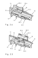
- FIG. 2.2 an isometric view of two contact carrier-halves for a mutual pushing onto the screen cross;
- FIG. 2.3 an isometric view of a contact carrier comprising two longitudinal halves to be snapped onto the screen cross;
- FIG. 2.4 an isometric view of a contact carrier comprising four segments to be snapped onto the screen cross;
- FIG. 3 a view of an electric contact
- FIG. 4 an isometric view of a round body
- FIG. 5 an isometric view of assembled contacts in the contact carrier, positioned on the screen cross;
- FIG. 6 an isometric view of a positioning aid
- FIG. 7 an isometric view of a completely assembled plug-in connector
- FIG. 8 a view of the connector side of the plug-in connector in a front-plate application
- FIG. 9 a view of the connector side of an angular plug-in connector on a circuit board in a front-plate application of a front plate
- FIG. 10 a straight plug-in connector, assembled perpendicular on a circuit board, surrounded by a front-plate insert.
- FIG. 1 shows an electrically conductive, axially expanding screen cross 10 for a plug-in connector 1 , with here by the cruciform structure four semi-open quadrants 16 develop with electric contacts 30 are to be arranged in pairs therein.
- the screen cross 10 is here formed from two walls 11 , 12 aligned perpendicular in reference to each other, with here at both sides of the vertical wall 11 the angular version shown comprising two vertical walls 13 abutting the horizontal wall 12 , in order to separate the upper and lower contacts 30 to be arranged here at a later time.
- the vertical and horizontal walls 11 , 12 each comprised on one side of axially-parallel aligned grooves 18 , in which beads 26 intended for this purpose engage the respective sides of the contact carrier 20 and serve for guiding the contact carriers 20 described in the following.
- the plug-in side geometry of the screen cross is predetermined by standards.
- first and second snap formations are provided at the external edges of the vertical and horizontal walls 11 , 12 and are respectively opposite thereto.
- formations 15 . 1 are here provided for latching a contact carrier 20 and the second latching formations 15 . 2 for a round body 40 to be pushed on at a later time.
- a ground pin 17 is provided at the screen cross 10 for an electric contacting with a circuit board 65 .
- FIG. 2.1 shows the basic example of a one-part contact carrier 20 . 1 with here the screen cross 10 can be inserted into its inner hollow space 29 .
- one equal sided inner edge 22 each is axially aligned at an angle of approx. 45°, which edge in turn comprises two accepting grooves 23 respectively provided side-by-side.
- the accepting grooves show different sections:
- a first section 24 . 1 shows an angular internal edge
- a second constricted section 24 . 2 is embodied as a round groove
- a third section 24 . 3 also comprising a round groove, but showing a larger diameter than the second section 24 . 2 .
- axial slots 27 with latching hooks 28 are provided along the external edges of the contact carrier 20 . 1 , with two opposite round bodies 40 each being intended to latch on the one side the screen cross 10 to the first latch formations 15 . 1 and the two second latch formations 15 . 2 , perpendicular in reference thereto, to latch to the round body 40 to be pushed onto the contact carrier 20 . 1
- FIG. 2.0 shows a particular embodiment disclosing such a similar contact carrier 20 . 1 connected by injection molding directly and in one piece with the screen cross 10 .
- FIG. 2.2 shows a multi-part contact carrier 20 . 2 with here two segment parts being provided, each of which can be pushed from a side axially onto the screen cross and held together with a pin-shaped latching means 25 . 1 encompassing the screen cross 10 in the middle at both sides of the latch formations 15 . 1 , 15 . 2 .
- respective recesses 21 . 2 are provided at the centered meeting sections of the respective external edges 21 of the contact carrier 20 . 2 .
- FIG. 2.3 shows a multi-part contact carrier, which comprises two individual segments 20 . 3 , embodied as similar half-shells and placed onto each other, surrounding the screen cross 10 , latched to each other.
- FIG. 2.4 shows four individual segments, but four similar segments 20 . 4 , arranged around the screen cross 10 , assembled and each latched to each other with latching means 25 . 2 .
- FIG. 2.5 ultimately shows a one-part contact carrier 20 . 5 here formed from four segments 20 . 6 each connected to each other via a film joint 20 . 7 , placed around the screen cross 10 , and with their ends can be latched to each other via latching means 25 . 3 .
- the different versions of the contact carrier are each called contact carrier 20 for reasons of simplification, because the external contours each show the same functional features.
- FIG. 3 shows the wire-shaped electric contact 30 , which comprises differently shaped sections, according to the differently shaped sections 24 in the accepting grooves 23 of the different contact carrier versions 20 .
- the plug-in side 31 of the electric contact 30 is either embodied as a pin or a socket, while the soldered side 32 . 1 is respectively angled by approx. 90° in reference to the axis.
- the lengths of the electric contacts 30 vary, with always the 1 st section 32 . 1 with the angled soldered side being embodied shorter or longer.
- next 2 nd section 32 . 2 in which the contact shows a four-sided form, which is inserted into the 1 st section 24 . 1 with the angular edge in the contact carrier 20 .
- This way a first rough alignment of the soldered sides is yielded for the later assembly on the circuit board 65 .
- the 3 rd section 32 . 3 is altogether provided for latching and holding the contact 30 in the second section 24 . 2 of the contact carrier 20 , while the 4 th section 32 . 4 , with a slightly larger diameter, is inserted into the long guiding groove 24 . 3 of the 3 rd section of the contact carrier 20 .
- the round body 40 is shown, which shall be pushed onto the cruciform structure comprising a screen cross 10 and a contact carrier 20 .
- the external round body 40 essentially showing round contours and comprising an electrically non-conductive material, is adjusted with its interior to the external cross shape of the contact carrier 20 .
- two opposite longitudinal slots 44 with latching hooks 45 are provided, with two latch formations 15 . 2 of the shielding cross 10 engaging for fixation.
- a circumferential annular groove 46 is formed in the round body 40 with the end of the longitudinal slot 44 , with a so-called screen spring 60 to be engaged, here.
- the screen spring may show a form deviating from the one shown here, though.
- the round body 40 shows a plug-in side 41 with four reference circle segments 42 , with respectively two bore holes 43 being formed therein for the plug-in sides 31 of the electric contacts 30 embodied as sockets or pins.
- the vertical and horizontal walls 11 , 12 of the screen cross 10 engage between these reference circle segments 42 , at least partially.
- FIG. 5 shows an already partially assembled plug-in connector, which comprises a screen cross 10 with the pushed-on contact carrier 20 as well as the electric contacts 30 inserted therein.
- FIG. 6 shows a positioning aid 50 for the alignment of the soldered sides 32 . 1 of the electric contacts 30 , which are assembled at the round body 40 and inserted via a fixation pin 55 on the circuit board 65 .
- the positioning aid 50 is first embodied as a flat disk 51 with two quarter-circle sections 52 on an elevated level.
- the soldered sides 32 . 1 of the electric contacts 30 are only inserted into the bore holes 53 . 1 at the higher sections 52 and subsequently the remaining contacts (are inserted) into the bore holes 53 . 2 of the flat section 5 . 1
- the bore holes 53 . 1 , 53 . 2 are arranged in the positioning aid 50 .
- a borehole 54 is additionally required for the ground pin 17 of the screen cross 10 . Furthermore, at the side facing the round body 40 two pins 57 are formed for fastening in the round body 40 , while at the opposite side at least one fixation pin 55 is provided for the circuit board 65 .
- a spacer is formed, not shown in greater detail here, in the form of an elevated, equal sided cross, for a distanced placement of the positioning aid on the circuit board 65 .
- FIG. 7 shows a plug-in connector 1 , confectioned to a certain extent, with additionally a positioning aid 50 being fastened thereat.
- the screen spring 60 in the circumferential groove 46 is discernible on the round body 40 , by which the contacting to a front plate insert 75 is ensured, described in the following.
- a screen spring 60 here shown in the form of a helical spring, accepts the ground contact between the screen cross 10 via the second latch formation 15 . 2 to the metallic, electrically conductive front plate insert 75 .
- a front plate insert 75 is provided for the round plug-in connector 1 , into which the round body 40 can be inserted, with via the screen spring 60 a contacting of the ground currents to the general housing mass being ensured by the front plate 70 .
- each of the four segments 42 of the complete plug-in connector 1 is hermetically and optimally sealed against external voltages with the electric contacts 30 arranged therein.
- FIG. 9 shows an angular plug-in connector 1 in a connection-side perspective, fixed on a circuit board 65 and “floating” in an insulating sheath, with a front-plate insert 75 being inserted.
- the plug-in connector 1 is here relatively exposed, the contacting with the screen spring is encased by the front plate insert 75 being screwed to a front plate 70 , with a counter plug to be contacted however being screwed tight to the front plate insert 75 or can be fastened by way of latching.
- a front plate insert 75 is shown, pushed onto the plug-in connector 2 .
- an insulation of the signals, secure from interfering radiation, is provided for the plug-in connector 1 , 2 at least by the front plate insert 75 .
Landscapes
- Details Of Connecting Devices For Male And Female Coupling (AREA)
- Coupling Device And Connection With Printed Circuit (AREA)
Applications Claiming Priority (4)
| Application Number | Priority Date | Filing Date | Title |
|---|---|---|---|
| DE102010034269.6 | 2010-08-13 | ||
| DE102010034269 | 2010-08-13 | ||
| DE102010034269 | 2010-08-13 | ||
| PCT/DE2011/075190 WO2012041310A1 (de) | 2010-08-13 | 2011-08-10 | Steckverbinder für differenzielle datenübertragung |
Publications (2)
| Publication Number | Publication Date |
|---|---|
| US20130137310A1 US20130137310A1 (en) | 2013-05-30 |
| US9502796B2 true US9502796B2 (en) | 2016-11-22 |
Family
ID=44862232
Family Applications (1)
| Application Number | Title | Priority Date | Filing Date |
|---|---|---|---|
| US13/816,837 Active US9502796B2 (en) | 2010-08-13 | 2011-08-10 | Plug connector for differential data transmission |
Country Status (11)
| Country | Link |
|---|---|
| US (1) | US9502796B2 (pl) |
| EP (1) | EP2603952B1 (pl) |
| JP (1) | JP5602947B2 (pl) |
| KR (1) | KR101465921B1 (pl) |
| CN (1) | CN103329359B (pl) |
| DE (1) | DE102010051954B3 (pl) |
| DK (1) | DK2603952T3 (pl) |
| ES (1) | ES2571404T3 (pl) |
| HU (1) | HUE027586T2 (pl) |
| PL (1) | PL2603952T3 (pl) |
| WO (1) | WO2012041310A1 (pl) |
Cited By (3)
| Publication number | Priority date | Publication date | Assignee | Title |
|---|---|---|---|---|
| US10763623B2 (en) * | 2017-10-10 | 2020-09-01 | HARTING Electronics GmbH | Printed circuit board connector having a shielding element |
| US20210184405A1 (en) * | 2019-12-13 | 2021-06-17 | TE Connectivity Services Gmbh | Cable connector |
| US20220069492A1 (en) * | 2018-12-17 | 2022-03-03 | Amphenol Tuchel Industrial GmbH | Multi-part printed circuit board adapter plug |
Families Citing this family (25)
| Publication number | Priority date | Publication date | Assignee | Title |
|---|---|---|---|---|
| DE102011052792B4 (de) * | 2011-08-18 | 2014-05-22 | HARTING Electronics GmbH | Isolierkörper mit Schirmkreuz |
| DE102012105256A1 (de) | 2012-06-18 | 2013-12-19 | HARTING Electronics GmbH | Isolierkörper eines Steckverbinders |
| DE102012105257B4 (de) | 2012-06-18 | 2018-06-07 | HARTING Electronics GmbH | Isolierkörper eines Steckverbinders |
| DE202012007577U1 (de) * | 2012-08-07 | 2012-09-13 | Rosenberger Hochfrequenztechnik Gmbh & Co. Kg | Steckverbinder |
| FR2997799B1 (fr) * | 2012-11-06 | 2015-01-30 | Souriau | Systeme pour connecter une embase de connecteur sur un boitier electronique et procede de montage de ce systeme |
| DE102012022004B3 (de) * | 2012-11-12 | 2014-02-06 | HARTING Electronics GmbH | Isolierkörper mit Schirmkreuz |
| DE102012111646B4 (de) * | 2012-11-30 | 2016-08-18 | HARTING Electronics GmbH | Isolierkörper mit integriertem Schirmelement |
| DE202013012011U1 (de) | 2013-02-05 | 2015-02-03 | HARTING Electronics GmbH | Steckverbindergehäuse |
| CN204067664U (zh) * | 2014-08-12 | 2014-12-31 | 泰科电子(上海)有限公司 | 电连接器 |
| DE202015100245U1 (de) * | 2015-01-21 | 2016-02-02 | FILTEC GmbH Filtertechnologie für die Elektronikindustrie | Steckerbuchsenanordnung umfassend eine abgeschirmte Steckerbuchse für Leiterplatten oder Platinen |
| CN104836043A (zh) * | 2015-05-12 | 2015-08-12 | 上海航天科工电器研究院有限公司 | 一种方圆形弯插连接器 |
| WO2017132959A1 (en) * | 2016-02-04 | 2017-08-10 | Harting (Zhuhai) Manufacturing Co., Ltd. | Plug connector with integrated galvanic separation |
| USD845246S1 (en) | 2016-07-26 | 2019-04-09 | Eaton Intelligent Power Limited | Electrical connector housing with asymmetric rectangular hot terminal edge slots and terminals with a rectangular edge protrusion |
| DE102017115914B3 (de) | 2017-07-14 | 2018-10-31 | HARTING Electronics GmbH | Leiterkartensteckverbinder mit einem Schirmelement |
| WO2019130038A1 (en) * | 2017-12-27 | 2019-07-04 | Drägerwerk AG & Co. KGaA | Rack mount |
| DE102018103639B3 (de) | 2018-02-19 | 2019-06-06 | Harting Electric Gmbh & Co. Kg | Leiterkartensteckverbinder mit einem Schirmanbindungselement |
| JP6709817B2 (ja) * | 2018-03-27 | 2020-06-17 | 矢崎総業株式会社 | コネクタ |
| JP6900927B2 (ja) * | 2018-04-04 | 2021-07-14 | 株式会社オートネットワーク技術研究所 | コネクタ |
| DE102018121582A1 (de) * | 2018-09-04 | 2020-03-05 | Rosenberger Hochfrequenztechnik Gmbh & Co. Kg | Elektrische Verteilervorrichtung, Montageverfahren und Signalübertragungssystem |
| DE102019106980B3 (de) * | 2019-03-19 | 2020-07-02 | Harting Electric Gmbh & Co. Kg | Kontaktträger und Steckverbinder für eine geschirmte hybride Kontaktanordnung |
| EP3829008A1 (en) | 2019-11-26 | 2021-06-02 | TE Connectivity Germany GmbH | Cable retainer insert and connector for shielding transfer |
| CN111430973B (zh) * | 2020-03-11 | 2021-06-11 | 上海航天科工电器研究院有限公司 | 一种8芯圆形1394信号接触件 |
| CN111541069B (zh) * | 2020-03-24 | 2021-11-23 | 上海航天科工电器研究院有限公司 | 一种全链路可靠屏蔽差分对结构 |
| DE102021102252A1 (de) | 2021-02-01 | 2022-08-04 | HARTING Electronics GmbH | Elektrisches Gerät, Geräteanschlussteil für das elektrische Gerät sowie Verfahren zur Herstellung eines elektrischen Gerätes |
| US11611168B2 (en) * | 2021-07-26 | 2023-03-21 | Te Connectivity Solutions Gmbh | Cable connector with contact holder latching to the outer shell |
Citations (24)
| Publication number | Priority date | Publication date | Assignee | Title |
|---|---|---|---|---|
| US4449779A (en) * | 1979-05-23 | 1984-05-22 | Hampshire Michael J | Electrical connector |
| EP0755100A2 (en) | 1996-02-29 | 1997-01-22 | Telesafe AS | Contact set for twisted pair cable with individually shielded pairs |
| EP0809331A1 (de) | 1996-05-23 | 1997-11-26 | BKS Kabel-Service AG | Mehrpoliges Steckersystem mit einer Steckdose und mindestens einem Stecker zum elektrischen und mechanischen Verbinden von elektrischen Leitern |
| JPH10340759A (ja) | 1997-05-30 | 1998-12-22 | Molex Inc | シールド電気コネクタ |
| US6077122A (en) | 1997-10-30 | 2000-06-20 | Thomas & Bett International, Inc. | Electrical connector having an improved connector shield and a multi-purpose strain relief |
| US6080018A (en) | 1998-06-30 | 2000-06-27 | The Whitaker Corporation | Grounding arrangement for a shielded cable connector |
| US6238246B1 (en) * | 1998-06-30 | 2001-05-29 | The Whitaker Corporation | Grounding bracket for a shielded cable connector |
| JP2002151207A (ja) | 2000-10-17 | 2002-05-24 | Molex Inc | 基板接続用コネクタ及びプラグコネクタの製造方法 |
| US20020115346A1 (en) | 1998-01-15 | 2002-08-22 | Maxwell Yip | Shielded outlet having contact tails shield |
| US6805590B2 (en) * | 2001-05-17 | 2004-10-19 | Yazaki Corporation | Multipolar connector |
| US6863545B2 (en) * | 2002-01-07 | 2005-03-08 | Molex Incorporated | Automotive connector with improved retention ability |
| DE202004014020U1 (de) | 2004-09-09 | 2006-02-09 | Krauss-Maffei Wegmann Gmbh & Co. Kg | Steckverbinder zur Leitungsdurchführung durch eine Öffnung einer Trennwand eines insbesondere militärischen Gerätes |
| US20060068618A1 (en) | 2004-09-27 | 2006-03-30 | Hon Hai Precision Ind. Co., Ltd. | Connector assembly having auxiliary device to support the connector against tilting |
| US20060246780A1 (en) | 2005-05-02 | 2006-11-02 | Tyco Electronics Corporation | Electrical connector with enhanced jack interface |
| CN1885623A (zh) | 2005-06-24 | 2006-12-27 | 哈廷电子有限公司及两合公司 | 用于差分信号传输的印刷电路板插接连接器 |
| US20070259568A1 (en) | 2005-09-13 | 2007-11-08 | Mackillop William J | Matched impedance shielded pair interconnection system for high reliability applications |
| EP1858117A1 (en) | 2006-05-17 | 2007-11-21 | Bel Fuse Ltd. | High speed data plug and method for assembling same |
| CN101127419A (zh) | 2006-07-31 | 2008-02-20 | 德尔菲技术公司 | 带直角接线端子插针的电连接器 |
| FR2921522A1 (fr) | 2007-09-20 | 2009-03-27 | Souriau Soc Par Actions Simpli | Connecteur pour cables ethernet et kit pour connecteur |
| US7575476B2 (en) * | 2007-08-01 | 2009-08-18 | Tyco Electronics Corporation | Power distribution module and header assembly therefor |
| US7736159B1 (en) | 2009-04-07 | 2010-06-15 | Tyco Electronics Corporation | Pluggable connector with differential pairs |
| US7811115B1 (en) * | 2008-12-12 | 2010-10-12 | Tyco Electronics Corporation | Connector assembly with two stage latch |
| US20120034809A1 (en) * | 2009-04-09 | 2012-02-09 | Phoenix Contact Gmbh & Co. Kg | Electrical plug-in connector and electrical plug-in connection |
| US9099814B2 (en) * | 2013-07-16 | 2015-08-04 | Delphi Technologies, Inc. | Shielded electrical header assembly |
Family Cites Families (1)
| Publication number | Priority date | Publication date | Assignee | Title |
|---|---|---|---|---|
| WO1999023727A1 (en) * | 1997-10-30 | 1999-05-14 | Thomas & Betts International, Inc. | Electrical connector having an improved connector shield and a multi-purpose strain relief |
-
2010
- 2010-11-19 DE DE102010051954A patent/DE102010051954B3/de active Active
-
2011
- 2011-08-10 CN CN201180039509.1A patent/CN103329359B/zh active Active
- 2011-08-10 KR KR1020137006329A patent/KR101465921B1/ko active IP Right Grant
- 2011-08-10 DK DK11775722.9T patent/DK2603952T3/en active
- 2011-08-10 PL PL11775722T patent/PL2603952T3/pl unknown
- 2011-08-10 JP JP2013524349A patent/JP5602947B2/ja not_active Expired - Fee Related
- 2011-08-10 ES ES11775722T patent/ES2571404T3/es active Active
- 2011-08-10 US US13/816,837 patent/US9502796B2/en active Active
- 2011-08-10 HU HUE11775722A patent/HUE027586T2/en unknown
- 2011-08-10 WO PCT/DE2011/075190 patent/WO2012041310A1/de active Application Filing
- 2011-08-10 EP EP11775722.9A patent/EP2603952B1/de active Active
Patent Citations (27)
| Publication number | Priority date | Publication date | Assignee | Title |
|---|---|---|---|---|
| US4449779A (en) * | 1979-05-23 | 1984-05-22 | Hampshire Michael J | Electrical connector |
| EP0755100A2 (en) | 1996-02-29 | 1997-01-22 | Telesafe AS | Contact set for twisted pair cable with individually shielded pairs |
| EP0809331A1 (de) | 1996-05-23 | 1997-11-26 | BKS Kabel-Service AG | Mehrpoliges Steckersystem mit einer Steckdose und mindestens einem Stecker zum elektrischen und mechanischen Verbinden von elektrischen Leitern |
| US5895292A (en) | 1996-05-23 | 1999-04-20 | Bks Kabel Service Ag | Multipolar connector system with an outlet and at least one connector for electrical and mechanical connection of electrical conductors |
| JPH10340759A (ja) | 1997-05-30 | 1998-12-22 | Molex Inc | シールド電気コネクタ |
| US6077122A (en) | 1997-10-30 | 2000-06-20 | Thomas & Bett International, Inc. | Electrical connector having an improved connector shield and a multi-purpose strain relief |
| US20020115346A1 (en) | 1998-01-15 | 2002-08-22 | Maxwell Yip | Shielded outlet having contact tails shield |
| US6080018A (en) | 1998-06-30 | 2000-06-27 | The Whitaker Corporation | Grounding arrangement for a shielded cable connector |
| US6238246B1 (en) * | 1998-06-30 | 2001-05-29 | The Whitaker Corporation | Grounding bracket for a shielded cable connector |
| JP2002151207A (ja) | 2000-10-17 | 2002-05-24 | Molex Inc | 基板接続用コネクタ及びプラグコネクタの製造方法 |
| US6805590B2 (en) * | 2001-05-17 | 2004-10-19 | Yazaki Corporation | Multipolar connector |
| US6863545B2 (en) * | 2002-01-07 | 2005-03-08 | Molex Incorporated | Automotive connector with improved retention ability |
| DE202004014020U1 (de) | 2004-09-09 | 2006-02-09 | Krauss-Maffei Wegmann Gmbh & Co. Kg | Steckverbinder zur Leitungsdurchführung durch eine Öffnung einer Trennwand eines insbesondere militärischen Gerätes |
| US20080045072A1 (en) | 2004-09-09 | 2008-02-21 | Andreas Heckmann | Plug-In Connector for Guiding a Cable Through an Opening of a Separating Wall of an, in Particular, Military Device |
| US20060068618A1 (en) | 2004-09-27 | 2006-03-30 | Hon Hai Precision Ind. Co., Ltd. | Connector assembly having auxiliary device to support the connector against tilting |
| US20060246780A1 (en) | 2005-05-02 | 2006-11-02 | Tyco Electronics Corporation | Electrical connector with enhanced jack interface |
| US7195518B2 (en) * | 2005-05-02 | 2007-03-27 | Tyco Electronics Corporation | Electrical connector with enhanced jack interface |
| CN1885623A (zh) | 2005-06-24 | 2006-12-27 | 哈廷电子有限公司及两合公司 | 用于差分信号传输的印刷电路板插接连接器 |
| US20070259568A1 (en) | 2005-09-13 | 2007-11-08 | Mackillop William J | Matched impedance shielded pair interconnection system for high reliability applications |
| EP1858117A1 (en) | 2006-05-17 | 2007-11-21 | Bel Fuse Ltd. | High speed data plug and method for assembling same |
| CN101127419A (zh) | 2006-07-31 | 2008-02-20 | 德尔菲技术公司 | 带直角接线端子插针的电连接器 |
| US7575476B2 (en) * | 2007-08-01 | 2009-08-18 | Tyco Electronics Corporation | Power distribution module and header assembly therefor |
| FR2921522A1 (fr) | 2007-09-20 | 2009-03-27 | Souriau Soc Par Actions Simpli | Connecteur pour cables ethernet et kit pour connecteur |
| US7811115B1 (en) * | 2008-12-12 | 2010-10-12 | Tyco Electronics Corporation | Connector assembly with two stage latch |
| US7736159B1 (en) | 2009-04-07 | 2010-06-15 | Tyco Electronics Corporation | Pluggable connector with differential pairs |
| US20120034809A1 (en) * | 2009-04-09 | 2012-02-09 | Phoenix Contact Gmbh & Co. Kg | Electrical plug-in connector and electrical plug-in connection |
| US9099814B2 (en) * | 2013-07-16 | 2015-08-04 | Delphi Technologies, Inc. | Shielded electrical header assembly |
Cited By (5)
| Publication number | Priority date | Publication date | Assignee | Title |
|---|---|---|---|---|
| US10763623B2 (en) * | 2017-10-10 | 2020-09-01 | HARTING Electronics GmbH | Printed circuit board connector having a shielding element |
| US20220069492A1 (en) * | 2018-12-17 | 2022-03-03 | Amphenol Tuchel Industrial GmbH | Multi-part printed circuit board adapter plug |
| US11881645B2 (en) * | 2018-12-17 | 2024-01-23 | Amphenol Tuchel Industrial GmbH | Multi-part printed circuit board adapter plug |
| US20210184405A1 (en) * | 2019-12-13 | 2021-06-17 | TE Connectivity Services Gmbh | Cable connector |
| US11095076B2 (en) * | 2019-12-13 | 2021-08-17 | TE Connectivity Services Gmbh | Cable connector |
Also Published As
| Publication number | Publication date |
|---|---|
| KR101465921B1 (ko) | 2014-11-26 |
| JP2013537693A (ja) | 2013-10-03 |
| ES2571404T3 (es) | 2016-05-25 |
| DE102010051954B3 (de) | 2012-02-09 |
| JP5602947B2 (ja) | 2014-10-08 |
| CN103329359B (zh) | 2016-06-01 |
| EP2603952A1 (de) | 2013-06-19 |
| HUE027586T2 (en) | 2016-10-28 |
| KR20130045388A (ko) | 2013-05-03 |
| DK2603952T3 (en) | 2016-05-17 |
| CN103329359A (zh) | 2013-09-25 |
| EP2603952B1 (de) | 2016-03-02 |
| WO2012041310A1 (de) | 2012-04-05 |
| US20130137310A1 (en) | 2013-05-30 |
| PL2603952T3 (pl) | 2016-08-31 |
Similar Documents
| Publication | Publication Date | Title |
|---|---|---|
| US9502796B2 (en) | Plug connector for differential data transmission | |
| RU2633388C2 (ru) | Модуль штекерного соединителя | |
| CN108346869B (zh) | 线缆连接器 | |
| US8840434B2 (en) | Rotatable plug-type connector | |
| US6948977B1 (en) | Connector assembly and assembly method | |
| KR20160029836A (ko) | 플러그 커넥터 | |
| JP2013025956A (ja) | シールドコネクタ及びシールドコネクタの組立方法 | |
| US9722348B2 (en) | System having a plurality of plug-in connectors and multiple plug-in connector | |
| CN107925183B (zh) | 插拔连接器 | |
| JP2015520498A (ja) | 差込式コネクタの絶縁体 | |
| KR20150004905A (ko) | 플러그 커넥터의 절연 바디 | |
| KR20160030136A (ko) | 삽입형 커넥터 | |
| CN111213292B (zh) | 具有屏蔽元件的印刷电路板插接连接器 | |
| KR101601819B1 (ko) | 스타 쿼드 케이블용 플러그 커넥터 | |
| KR200494760Y1 (ko) | 무방향성 선-기판 커넥터 | |
| CN110870146B (zh) | 具有屏蔽元件的印刷电路板插接连接器 | |
| US11450989B2 (en) | Plug-in connector with ground terminal region | |
| TW201911685A (zh) | 轉接器總成及轉接器 | |
| JP2001357944A (ja) | プラグコネクタ | |
| US20230198187A1 (en) | Electrical Plug Connector and Method for Assembling an Electrical Plug Connector | |
| TW201347319A (zh) | 同軸連接器 | |
| US20230231342A1 (en) | Connection element and electronic component part with multiple plug-in positions for two-wire technology | |
| CN113841302B (zh) | 用于屏蔽混合触头组件的触头载体及插接连接器 | |
| TWI656700B (zh) | 垂直式高速連接器及其導電模組 | |
| TWM646261U (zh) | 連接器 |
Legal Events
| Date | Code | Title | Description |
|---|---|---|---|
| AS | Assignment |
Owner name: HARTING ELECTRONICS GMBH & CO. KG, GERMANY Free format text: ASSIGNMENT OF ASSIGNORS INTEREST;ASSIGNOR:GENAU, MELANIE;REEL/FRAME:029805/0884 Effective date: 20130205 |
|
| AS | Assignment |
Owner name: HARTING ELECTRONICS GMBH, GERMANY Free format text: CHANGE OF NAME;ASSIGNOR:HARTING ELECTRONICS GMBH & CO. KG;REEL/FRAME:030334/0234 Effective date: 20130225 |
|
| STCF | Information on status: patent grant |
Free format text: PATENTED CASE |
|
| MAFP | Maintenance fee payment |
Free format text: PAYMENT OF MAINTENANCE FEE, 4TH YEAR, LARGE ENTITY (ORIGINAL EVENT CODE: M1551); ENTITY STATUS OF PATENT OWNER: LARGE ENTITY Year of fee payment: 4 |
|
| MAFP | Maintenance fee payment |
Free format text: PAYMENT OF MAINTENANCE FEE, 8TH YEAR, LARGE ENTITY (ORIGINAL EVENT CODE: M1552); ENTITY STATUS OF PATENT OWNER: LARGE ENTITY Year of fee payment: 8 |