US9501085B2 - Method and apparatus for pulse generation - Google Patents
Method and apparatus for pulse generation Download PDFInfo
- Publication number
- US9501085B2 US9501085B2 US11/701,051 US70105107A US9501085B2 US 9501085 B2 US9501085 B2 US 9501085B2 US 70105107 A US70105107 A US 70105107A US 9501085 B2 US9501085 B2 US 9501085B2
- Authority
- US
- United States
- Prior art keywords
- waveform
- description
- segment
- generator
- pulse
- Prior art date
- Legal status (The legal status is an assumption and is not a legal conclusion. Google has not performed a legal analysis and makes no representation as to the accuracy of the status listed.)
- Active, expires
Links
Images

Classifications
-
- G—PHYSICS
- G06—COMPUTING OR CALCULATING; COUNTING
- G06F—ELECTRIC DIGITAL DATA PROCESSING
- G06F1/00—Details not covered by groups G06F3/00 - G06F13/00 and G06F21/00
- G06F1/02—Digital function generators
- G06F1/022—Waveform generators, i.e. devices for generating periodical functions of time, e.g. direct digital synthesizers
Definitions
- the present invention relates to test instruments and, in particular, to the generation of pulse waveforms for testing.
- the generation of testing signals for devices has become increasing important as testing has moved towards 100 percent testing, exhaustive multiple parameter testing and lifetime testing. All of these trends have created a need for easily selected and produced pulse waveforms.
- the desire waveforms may include multiple pulses, multi-level pulses or both.
- a method and apparatus for generating a desired pulse waveform including: dividing the desired pulse waveform into a plurality of line segments; assigning to each line segment at least a segment identification, a segment initial value, and a segment duration to form a waveform description; providing the waveform description to a pulse generator.
- the pulse generator is operable to produce a waveform corresponding to the waveform description and to output the produced waveform.
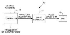
- FIG. 1 is a block diagram of an example of a waveform generator according to the invention.
- FIG. 2 is a graphical representation of an example of a waveform description according to the invention.
- a waveform generator 10 includes a controller 12 and a pulse generator 14 .
- the waveform generator 10 supplies a pulse waveform to a device under test (DUT) 16 .
- DUT device under test
- a desired waveform is input to the controller 12 and a waveform description corresponding thereto is provided by the controller 12 to the pulse generator 14 .
- the pulse generator 14 then produces the pulse waveform according to the waveform description.
- the pulse generator 14 may be, for example, a digitally controlled voltage source that is programmed to supply output signal waveforms in response to the waveform description.
- the controller 12 may be, for example, a general purpose computer, a programmable controller, a FPGA, or similar devices.
- an example desired waveform is shown.
- the waveform is divided into a series of line segments indicated by the broken lines.
- An example waveform description is listed below the desired waveform.
- For each line segment there is at least a segment identification (e.g., Seg 1 , Seg 2 . . . ), an initial value (e.g., V A , V B . . . ) and a duration (e.g., D A , D B . . . ). It is also possible to specify a final value for each segment, but using the initial value of the next segment is simpler.
- the controller 12 may have stored waveform descriptions that are selected by a user or additional test control devices, based on a desired waveform input selection, or the controller 12 may create waveform descriptions as needed based on the input of desired input waveforms themselves. Also, combinations of stored and as-needed descriptions may be used.
- the pulse generator 14 assembles each of the line segments in the waveform description into a pulse waveform for application to the DUT 16 .
- a segment may also include a trigger value (e.g., T A , T A . . . ).
- the trigger values can be used to synchronize one or more additional desired pulse waveforms.
- the trigger value may specify another waveform generator and when a segment in that waveform generator is to occur.
- each segment may also have an impedance state (e.g., L and H). If the state is H, the waveform generator 10 appears to be disconnected from the DUT 16 . If the state is L, the DUT 16 sees the appropriate load impedance (e.g., 50 ohms).
- the method and apparatus of the invention provides a simple control interface (e.g., tables of segments) which includes a convenient way of handling wide ranges of time bases (e.g., nanoseconds to multiple seconds)
Landscapes
- Engineering & Computer Science (AREA)
- Theoretical Computer Science (AREA)
- Physics & Mathematics (AREA)
- General Engineering & Computer Science (AREA)
- General Physics & Mathematics (AREA)
- Tests Of Electronic Circuits (AREA)
Abstract
Description
Claims (6)
Priority Applications (2)
| Application Number | Priority Date | Filing Date | Title |
|---|---|---|---|
| US11/701,051 US9501085B2 (en) | 2007-02-01 | 2007-02-01 | Method and apparatus for pulse generation |
| JP2008020232A JP4953019B2 (en) | 2007-02-01 | 2008-01-31 | Method and apparatus for pulse generation |
Applications Claiming Priority (1)
| Application Number | Priority Date | Filing Date | Title |
|---|---|---|---|
| US11/701,051 US9501085B2 (en) | 2007-02-01 | 2007-02-01 | Method and apparatus for pulse generation |
Publications (2)
| Publication Number | Publication Date |
|---|---|
| US20080186065A1 US20080186065A1 (en) | 2008-08-07 |
| US9501085B2 true US9501085B2 (en) | 2016-11-22 |
Family
ID=39675626
Family Applications (1)
| Application Number | Title | Priority Date | Filing Date |
|---|---|---|---|
| US11/701,051 Active 2030-06-10 US9501085B2 (en) | 2007-02-01 | 2007-02-01 | Method and apparatus for pulse generation |
Country Status (2)
| Country | Link |
|---|---|
| US (1) | US9501085B2 (en) |
| JP (1) | JP4953019B2 (en) |
Families Citing this family (1)
| Publication number | Priority date | Publication date | Assignee | Title |
|---|---|---|---|---|
| FR2973971B1 (en) * | 2011-04-08 | 2013-05-10 | Centre Nat Rech Scient | DIRECT DIGITAL SYNTHESIS SIGNAL SYNTHESIZER WITH VARIABLE AMPLITUDE INCREMENT GENERATOR |
Citations (11)
| Publication number | Priority date | Publication date | Assignee | Title |
|---|---|---|---|---|
| JPS6436116A (en) | 1987-07-31 | 1989-02-07 | Nec Corp | Timing pulse generating circuit |
| JPH10319096A (en) | 1997-05-21 | 1998-12-04 | Advantest Corp | Semiconductor testing device |
| JPH1195862A (en) | 1997-09-19 | 1999-04-09 | Ando Electric Co Ltd | Pattern generation circuit |
| US5945822A (en) * | 1996-09-05 | 1999-08-31 | Advantest Corporation | Programmable load circuit |
| US6119257A (en) * | 1997-02-21 | 2000-09-12 | Advantest Corporation | Semiconductor device testing apparatus capable of high speed test operation |
| US20020080202A1 (en) * | 2000-10-16 | 2002-06-27 | Brother Kogyo Kabushiki Kaisha | Ink ejection apparatus |
| US6545513B2 (en) * | 2001-05-17 | 2003-04-08 | Denso Corporation | Electric load drive apparatus |
| US6636124B1 (en) * | 2001-11-30 | 2003-10-21 | Analog Technologies, Inc. | Method and apparatus for accurate pulse width modulation |
| US7023153B2 (en) * | 2002-06-19 | 2006-04-04 | Kabushiki Kaisha Yaskawa Denki | Motor control device |
| US7068082B2 (en) * | 2003-07-25 | 2006-06-27 | Kabushiki Kaisha Toshiba | Gate driving circuit and semiconductor device |
| JP2006333272A (en) | 2005-05-27 | 2006-12-07 | Tektronix Japan Ltd | Data pattern generator |
Family Cites Families (4)
| Publication number | Priority date | Publication date | Assignee | Title |
|---|---|---|---|---|
| JPH0787298B2 (en) * | 1986-02-24 | 1995-09-20 | 株式会社日立製作所 | Periodic function signal generator |
| US5818238A (en) * | 1996-03-15 | 1998-10-06 | Symetrix Corporation | Apparatus for measuring current and other parameters of an electornic device in response to an applied voltage |
| US6018246A (en) * | 1997-10-17 | 2000-01-25 | Hewlett-Packard Company | Network analyzer measurement method for high dynamic range devices |
| JP2001343429A (en) * | 2000-06-01 | 2001-12-14 | Sony Corp | Test apparatus and test method for semiconductor device |
-
2007
- 2007-02-01 US US11/701,051 patent/US9501085B2/en active Active
-
2008
- 2008-01-31 JP JP2008020232A patent/JP4953019B2/en not_active Expired - Fee Related
Patent Citations (11)
| Publication number | Priority date | Publication date | Assignee | Title |
|---|---|---|---|---|
| JPS6436116A (en) | 1987-07-31 | 1989-02-07 | Nec Corp | Timing pulse generating circuit |
| US5945822A (en) * | 1996-09-05 | 1999-08-31 | Advantest Corporation | Programmable load circuit |
| US6119257A (en) * | 1997-02-21 | 2000-09-12 | Advantest Corporation | Semiconductor device testing apparatus capable of high speed test operation |
| JPH10319096A (en) | 1997-05-21 | 1998-12-04 | Advantest Corp | Semiconductor testing device |
| JPH1195862A (en) | 1997-09-19 | 1999-04-09 | Ando Electric Co Ltd | Pattern generation circuit |
| US20020080202A1 (en) * | 2000-10-16 | 2002-06-27 | Brother Kogyo Kabushiki Kaisha | Ink ejection apparatus |
| US6545513B2 (en) * | 2001-05-17 | 2003-04-08 | Denso Corporation | Electric load drive apparatus |
| US6636124B1 (en) * | 2001-11-30 | 2003-10-21 | Analog Technologies, Inc. | Method and apparatus for accurate pulse width modulation |
| US7023153B2 (en) * | 2002-06-19 | 2006-04-04 | Kabushiki Kaisha Yaskawa Denki | Motor control device |
| US7068082B2 (en) * | 2003-07-25 | 2006-06-27 | Kabushiki Kaisha Toshiba | Gate driving circuit and semiconductor device |
| JP2006333272A (en) | 2005-05-27 | 2006-12-07 | Tektronix Japan Ltd | Data pattern generator |
Also Published As
| Publication number | Publication date |
|---|---|
| US20080186065A1 (en) | 2008-08-07 |
| JP2008193689A (en) | 2008-08-21 |
| JP4953019B2 (en) | 2012-06-13 |
Similar Documents
| Publication | Publication Date | Title |
|---|---|---|
| JPH04218785A (en) | Ic tester | |
| KR870004454A (en) | Test Pattern Generator | |
| US9501085B2 (en) | Method and apparatus for pulse generation | |
| EP1947467A1 (en) | Testing apparatus and performance board | |
| US8400179B1 (en) | Method for load-line correction of pulsed measurements | |
| EP2772861A1 (en) | Semiconductor test device and semiconductor test method | |
| JPH0481675A (en) | Apparatus for testing semiconductor device | |
| CN103915120A (en) | Memory bar voltage testing device and method thereof | |
| KR101039845B1 (en) | Timing generating device and method using ffigeA | |
| US6535831B1 (en) | Method for sourcing three level data from a two level tester pin faster than the maximum rate of a tester | |
| JPWO2003040739A1 (en) | Semiconductor device test equipment | |
| JP5171811B2 (en) | Test apparatus and electronic device | |
| CA2529404A1 (en) | Method and system for depicting digital display elements | |
| CN111028800B (en) | Signal compensation method, apparatus, system, electronic device and storage medium | |
| US8451030B2 (en) | Output device and test apparatus | |
| US20250164594A1 (en) | Multiple output instrument calibrator | |
| CN104764942A (en) | Automatic test equipment and its control method | |
| RU2225013C2 (en) | Automated system testing electrical quantities of electron equipment | |
| US11326948B2 (en) | Method and system for generating an electromagnetic signal | |
| KR20010004387A (en) | Device and method for testing Memory module | |
| US7246017B2 (en) | Waveform measuring apparatus for measuring waveform data and writing measurement data to acquisition memory | |
| JP4678347B2 (en) | Mixed signal LSI tester and test pattern generation method | |
| CN101233417A (en) | Programmable Pin Electronics Driver | |
| JPH01121779A (en) | Ic testing device | |
| CN121856601A (en) | Waveform excitation signal generation method and device of automatic test system |
Legal Events
| Date | Code | Title | Description |
|---|---|---|---|
| AS | Assignment |
Owner name: KEITHLEY INSTRUMENTS, INC., OHIO Free format text: ASSIGNMENT OF ASSIGNORS INTEREST;ASSIGNORS:HULBERT, PETE;RAYMAN, MICHAEL;GOTTLOB, TRISH;AND OTHERS;REEL/FRAME:019394/0395 Effective date: 20070529 |
|
| AS | Assignment |
Owner name: KEITHLEY INSTRUMENTS, INC., OHIO Free format text: ASSIGNMENT OF ASSIGNORS INTEREST;ASSIGNORS:HULBERT, PETE;RAYMAN, MICHAEL;GOTTLOB, TRISH;AND OTHERS;REEL/FRAME:019470/0506 Effective date: 20070529 |
|
| AS | Assignment |
Owner name: KEITHLEY INSTRUMENTS, LLC, OHIO Free format text: ASSIGNMENT OF ASSIGNORS INTEREST;ASSIGNOR:KEITHLEY INSTRUMENTS, INC.;REEL/FRAME:039946/0639 Effective date: 20161004 |
|
| STCF | Information on status: patent grant |
Free format text: PATENTED CASE |
|
| MAFP | Maintenance fee payment |
Free format text: PAYMENT OF MAINTENANCE FEE, 4TH YEAR, LARGE ENTITY (ORIGINAL EVENT CODE: M1551); ENTITY STATUS OF PATENT OWNER: LARGE ENTITY Year of fee payment: 4 |
|
| MAFP | Maintenance fee payment |
Free format text: PAYMENT OF MAINTENANCE FEE, 8TH YEAR, LARGE ENTITY (ORIGINAL EVENT CODE: M1552); ENTITY STATUS OF PATENT OWNER: LARGE ENTITY Year of fee payment: 8 |