US9497693B2 - Extension carrier discovery for carrier aggregation - Google Patents
Extension carrier discovery for carrier aggregation Download PDFInfo
- Publication number
- US9497693B2 US9497693B2 US14/344,989 US201214344989A US9497693B2 US 9497693 B2 US9497693 B2 US 9497693B2 US 201214344989 A US201214344989 A US 201214344989A US 9497693 B2 US9497693 B2 US 9497693B2
- Authority
- US
- United States
- Prior art keywords
- user equipment
- base station
- small cell
- secondary carrier
- carrier link
- Prior art date
- Legal status (The legal status is an assumption and is not a legal conclusion. Google has not performed a legal analysis and makes no representation as to the accuracy of the status listed.)
- Active, expires
Links
- 230000002776 aggregation Effects 0.000 title description 30
- 238000004220 aggregation Methods 0.000 title description 30
- 230000005540 biological transmission Effects 0.000 claims abstract description 102
- 238000005259 measurement Methods 0.000 claims description 113
- 230000011664 signaling Effects 0.000 claims description 81
- 238000004891 communication Methods 0.000 claims description 68
- 238000000034 method Methods 0.000 claims description 47
- 125000004122 cyclic group Chemical group 0.000 claims description 19
- 238000013468 resource allocation Methods 0.000 claims description 14
- 230000001934 delay Effects 0.000 claims description 11
- 239000000969 carrier Substances 0.000 description 23
- 230000002829 reductive effect Effects 0.000 description 14
- 230000001360 synchronised effect Effects 0.000 description 14
- 238000010586 diagram Methods 0.000 description 9
- 230000008054 signal transmission Effects 0.000 description 9
- 230000010267 cellular communication Effects 0.000 description 8
- 230000006870 function Effects 0.000 description 6
- 230000008901 benefit Effects 0.000 description 4
- 230000015556 catabolic process Effects 0.000 description 4
- 238000006731 degradation reaction Methods 0.000 description 4
- 230000004044 response Effects 0.000 description 4
- 238000005516 engineering process Methods 0.000 description 3
- 230000008569 process Effects 0.000 description 3
- 230000006399 behavior Effects 0.000 description 2
- 230000003247 decreasing effect Effects 0.000 description 2
- 230000003111 delayed effect Effects 0.000 description 2
- 238000001914 filtration Methods 0.000 description 2
- 230000007774 longterm Effects 0.000 description 2
- 238000010295 mobile communication Methods 0.000 description 2
- 230000004048 modification Effects 0.000 description 2
- 238000012986 modification Methods 0.000 description 2
- 238000012546 transfer Methods 0.000 description 2
- 108010076504 Protein Sorting Signals Proteins 0.000 description 1
- 230000004308 accommodation Effects 0.000 description 1
- 230000002411 adverse Effects 0.000 description 1
- 239000011324 bead Substances 0.000 description 1
- 230000008859 change Effects 0.000 description 1
- 230000001419 dependent effect Effects 0.000 description 1
- 230000008030 elimination Effects 0.000 description 1
- 238000003379 elimination reaction Methods 0.000 description 1
- 238000005562 fading Methods 0.000 description 1
- 238000009432 framing Methods 0.000 description 1
- 230000010354 integration Effects 0.000 description 1
- 230000002452 interceptive effect Effects 0.000 description 1
- 230000014759 maintenance of location Effects 0.000 description 1
- 238000007726 management method Methods 0.000 description 1
- 238000004519 manufacturing process Methods 0.000 description 1
- 238000013507 mapping Methods 0.000 description 1
- 238000007620 mathematical function Methods 0.000 description 1
- 230000036961 partial effect Effects 0.000 description 1
- 238000012545 processing Methods 0.000 description 1
Images


Classifications
-
- H—ELECTRICITY
- H04—ELECTRIC COMMUNICATION TECHNIQUE
- H04W—WIRELESS COMMUNICATION NETWORKS
- H04W48/00—Access restriction; Network selection; Access point selection
- H04W48/16—Discovering, processing access restriction or access information
-
- H—ELECTRICITY
- H04—ELECTRIC COMMUNICATION TECHNIQUE
- H04L—TRANSMISSION OF DIGITAL INFORMATION, e.g. TELEGRAPHIC COMMUNICATION
- H04L1/00—Arrangements for detecting or preventing errors in the information received
- H04L1/20—Arrangements for detecting or preventing errors in the information received using signal quality detector
-
- H—ELECTRICITY
- H04—ELECTRIC COMMUNICATION TECHNIQUE
- H04L—TRANSMISSION OF DIGITAL INFORMATION, e.g. TELEGRAPHIC COMMUNICATION
- H04L27/00—Modulated-carrier systems
- H04L27/26—Systems using multi-frequency codes
- H04L27/2601—Multicarrier modulation systems
-
- H—ELECTRICITY
- H04—ELECTRIC COMMUNICATION TECHNIQUE
- H04L—TRANSMISSION OF DIGITAL INFORMATION, e.g. TELEGRAPHIC COMMUNICATION
- H04L5/00—Arrangements affording multiple use of the transmission path
- H04L5/0001—Arrangements for dividing the transmission path
- H04L5/0003—Two-dimensional division
- H04L5/0005—Time-frequency
- H04L5/0007—Time-frequency the frequencies being orthogonal, e.g. OFDM(A), DMT
- H04L5/001—Time-frequency the frequencies being orthogonal, e.g. OFDM(A), DMT the frequencies being arranged in component carriers
-
- H—ELECTRICITY
- H04—ELECTRIC COMMUNICATION TECHNIQUE
- H04L—TRANSMISSION OF DIGITAL INFORMATION, e.g. TELEGRAPHIC COMMUNICATION
- H04L5/00—Arrangements affording multiple use of the transmission path
- H04L5/003—Arrangements for allocating sub-channels of the transmission path
- H04L5/0048—Allocation of pilot signals, i.e. of signals known to the receiver
-
- H—ELECTRICITY
- H04—ELECTRIC COMMUNICATION TECHNIQUE
- H04W—WIRELESS COMMUNICATION NETWORKS
- H04W48/00—Access restriction; Network selection; Access point selection
- H04W48/08—Access restriction or access information delivery, e.g. discovery data delivery
- H04W48/12—Access restriction or access information delivery, e.g. discovery data delivery using downlink control channel
-
- H—ELECTRICITY
- H04—ELECTRIC COMMUNICATION TECHNIQUE
- H04W—WIRELESS COMMUNICATION NETWORKS
- H04W72/00—Local resource management
- H04W72/04—Wireless resource allocation
- H04W72/044—Wireless resource allocation based on the type of the allocated resource
- H04W72/0453—Resources in frequency domain, e.g. a carrier in FDMA
-
- H—ELECTRICITY
- H04—ELECTRIC COMMUNICATION TECHNIQUE
- H04L—TRANSMISSION OF DIGITAL INFORMATION, e.g. TELEGRAPHIC COMMUNICATION
- H04L5/00—Arrangements affording multiple use of the transmission path
- H04L5/0001—Arrangements for dividing the transmission path
- H04L5/0014—Three-dimensional division
- H04L5/0016—Time-frequency-code
-
- H—ELECTRICITY
- H04—ELECTRIC COMMUNICATION TECHNIQUE
- H04W—WIRELESS COMMUNICATION NETWORKS
- H04W84/00—Network topologies
- H04W84/02—Hierarchically pre-organised networks, e.g. paging networks, cellular networks, WLAN [Wireless Local Area Network] or WLL [Wireless Local Loop]
- H04W84/04—Large scale networks; Deep hierarchical networks
- H04W84/042—Public Land Mobile systems, e.g. cellular systems
- H04W84/045—Public Land Mobile systems, e.g. cellular systems using private Base Stations, e.g. femto Base Stations, home Node B
-
- H—ELECTRICITY
- H04—ELECTRIC COMMUNICATION TECHNIQUE
- H04W—WIRELESS COMMUNICATION NETWORKS
- H04W88/00—Devices specially adapted for wireless communication networks, e.g. terminals, base stations or access point devices
- H04W88/08—Access point devices
- H04W88/085—Access point devices with remote components
Definitions
- This matter relates to carrier aggregation, and more particularly to balancing the conflicting demands of mobility performance and power consumption in a user equipment through novel cell discovery techniques.
- LTE Long Term Evolution
- WCDMA Wideband Code Division Multiple Access
- HSDPA High Speed Downlink Packet Access
- OFDMA Orthogonal Frequency Division Multiple Access
- SC-FDMA Single-Carrier Frequency Division Multiple Access
- SC-FDMA is closely related to OFDMA and was chosen for uplink to provide a lower peak-to-average power ratio. Such a ratio is not as important in downlink and thus OFDMA is suitable for downlink.
- OFDMA is advantageous in that it enables the high data rates that are envisioned for 4G systems.
- data is sent in a serial fashion.
- each data symbol must occupy a relatively brief timespan so as to achieve the desired high data rate. For example, if a system is to achieve 100 Mbps and the data is sent serially, each binary data symbol would have a period of just 0.01 ⁇ s. If the channel were perfect, such a symbol length would be no problem. But the channel for real-world cellular communication systems is far from perfect: there are lots of buildings, structures, and other obstacles that reflect the signal and introduce multipath. In a multipath channel, various delayed versions of the signal are received in addition to any un-reflected signal.
- OFDMA inter-symbol interference
- OFDMA modulates a high-speed serial data stream onto a parallel stream of various subcarriers. Each subcarrier has a relatively slow data rate, which mitigates the ISI.
- the subcarriers are readily produced through Fourier transform processes. Thus, a handset need have just a single oscillator to produce all the required subcarriers, which eases production costs. Because OFDMA enables robust high-speed and spectrally efficient data transmission at relatively low cost, older technologies such as CDMA are being rapidly phased out in favor of OFDMA systems such as LTE.
- LTE is advantageous as compared to older technologies, it still faces numerous technical challenges.
- the desired downlink data rate for LTE is 100 Mbps.
- the LTE coding rate is reduced accordingly.
- the LTE goal of 100 Mbps remains largely theoretical in many environments.
- the channel bandwidth is the maximum single channel bandwidth under the LTE standard for any given carrier.
- each subcarrier is separated by 15 KHz from adjacent subcarriers. Thus, any given amount of bandwidth can only accommodate so many subcarriers.
- the subcarriers are arranged in resource blocks. A 20 MHz channel can thus accommodate only 100 resource blocks. If the channel conditions are such that the subcarriers in each resource block are modulated at a relatively low coding rate, then there is only so much data that can be sent through a 20 MHz channel. In contrast, higher data rates can be achieved with higher coding rates such as 64 QAM. But a handset cannot readily decode 64 QAM unless the channel is of good quality. It is thus often the case that LTE data rate goals cannot be achieved even using the maximum 20 MHz channel bandwidth.
- Carrier aggregation allows a communication system such as an LTE system to get around this bandwidth bottleneck.
- the user equipment may receive (or may transmit) data on multiple carriers.
- Each carrier is referred to as a component carrier.
- a base station could use 5 component carriers to provide five 20 MHz channels between it and the handset.
- carrier aggregation thus greatly aids in achieving high data rates, it comes with assorted technical challenges as well. By and large, the data demands for given handset are such that carrier aggregation is not necessary. It is only during periods win which a user equipment is running a data-hungry application such as downloading high-definition video that carrier aggregation becomes necessary.
- Each secondary component carrier may also be denoted as an “extension carrier” in that the bandwidth is being extended through carrier aggregation.
- the secondary component carriers may be denoted as “inter-frequency carriers” in that they are of different frequencies as compared to the primary component carrier.
- a user equipment corresponds to a mobile user that is moving away from the serving base station to a neighboring one, that UE should be able to discover this neighboring base station so that a handoff decision can be made.
- this handoff decision is based on the received signal quality at the UE. As the UE gets closer to a neighboring base station and farther away from the serving base station, there will be a point when the signals from the neighboring base station are of better quality than those received from the serving base station. When this signal quality difference is deemed sufficient, the UE should be handed off to the neighboring base station. The neighboring base station thus becomes the serving base station pursuant to the handoff.
- an Event A3 is defined as a measurement event in TS 36.331, V10.2.0, 2011-06 regarding such a handoff decision.
- hysteresis is used to minimize “ping-ponging” (repeated handing off back and forth with regard to a pair of base stations).
- the UE makes a radio link quality (RLQ) measurement of the neighboring base station as well as an RLQ measurement for the serving base station.
- RLQ Neighbor ⁇ Hysteresis>RLQ Serving where RLQ neighbor is the radio link quality of a neighbor cell and RLQS erving is the radio link quality of the serving cell.
- This handoff decision can be made by the serving base station based upon the RLQ measurements by the UE.
- the radio link quality measurements may be based on the Reference Signal Received Power (RSRP) or the Reference Signal Received Quality (RSRQ), both of which are defined in TS 36.214, V10.1.0, 2011-03. In general, both RSRP and RSRQ measurements are conducted based on received common reference signals.
- the RSRP/RSRQ measurements may be simply denoted as “measurements.” Alternatively, a combination of the RSRP/RSRQ measurements and a cell search may be denoted as “measurements.”
- the user equipment makes RSRP or RSRQ measurements for the serving cell and for identified neighbor cells once every 40 ms, for example.
- the periodicity of the RSRP or RSRQ measurements can depend upon the particular user equipment being implemented. It may also depend on whether the user equipment is in a Discontinuous Reception (DRX) state or in a no-DRX state.
- DRX Discontinuous Reception
- the user equipment needs to continuously conduct cell search for yet-unidentified cells, in addition to RSRP or RSRQ measurements for the identified neighbor cells.
- the user equipment conducts the search for new cells utilizing the primary synchronization signals (PSS)/secondary synchronization signals (SSS), which are transmitted once per 5 ms.
- PSS primary synchronization signals
- SSS secondary synchronization signals
- Periodicity of the cell search is dependent upon the particular UE implementation and may also depend on whether the user equipment is in DRX state or in no-DRX state.
- the periodicity of the measurements and associated cell search greatly affects battery power consumption in the user equipment.
- mobility is enhanced if the user equipment conducts cell search and measurements very frequently but this mobility enhancement comes at the cost of increased power consumption, which is problematic for battery-powered devices.
- power consumption may be reduced if the user equipment conducts cell search and measurements relatively infrequently but this power consumption advantage comes at the cost of reduced mobility performance. A tradeoff must thus be made to balance mobility performance and power consumption.
- cell search/measurements not only for intra-frequency carrier corresponding to neighbor cells, but also for secondary component carriers.
- cell search/measurements for the inter-frequency or inter-Radio Access Technology (RAT) carrier may need more power consumption than those for the intra-frequency carrier.
- RAT Radio Access Technology
- a new beacon signal is introduced that provides an advantageous balance between mobility performance and power consumption.
- This beacon signal is carried by the secondary component carrier but is time synchronized with the primary component carrier or other reference carrier. Since the beacon signal transmissions are time synchronized with the primary component carrier, the user equipment can omit the conventional cell search. In this fashion, the user equipment can identify neighbor cells with just one attempt or just a few attempts of receiving the beacon signals. If the beacon signal has a cyclic prefix, the time synchronization with the primary component carrier need not be too precise.
- the secondary carrier may be transmitted by a network node removed from the base station such as through a remote radio head (RRH).
- RRH remote radio head
- the different propagation delays between the user equipment (UE) and the base station/RRH causes the secondary carrier to be received at the UE offset in time with regard to the primary component carrier time framing. But so long as this delay is within the cyclic prefix period, such a lack of perfect synchronization is harmless.
- the UE may be informed by the base station of the timing offset so that the UE can adjust its reception accordingly. In this fashion, the UE need not hunt for the beacon signal but can identify it within just a few attempts or less. As a result, the power consumptions for cell identification can be reduced.
- the discovery measurement rate or frequency by the UE for the secondary component carrier can also be reduced to further limit power consumption. Because of the time synchronization with the reference carrier, no degradation may be observed if the reference carrier mobility performance is maintained. In particular, no degradation in mobility performance occurs even as the measurement rate is decreased if the mobile speed is not high.
- performance requirements in a DRX system are specified in TS 36.133, V10.3.0, 2011-06 based on assumptions that the user equipment makes measurements once per every DRX cycle, even if the maximum value of the DRX cycle is 2.56 seconds. It can thus be expected that the measurement for the novel beacon signal disclosed herein may be reduced to once every 2.56 seconds yet still achieve satisfactory mobility performance in a low mobile speed scenario.
- the synchronization signals such as the primary synchronization signal (PSS) and the secondary synchronization signal (SSS) are modified with regard to conventional PSS/SSS signals.
- PSS primary synchronization signal
- SSS secondary synchronization signal
- the PSS/SSS signals are generated in specific subframes.
- the modified PSS/SSS signals disclosed herein involve a cell specific timing for each cell that must be discovered.
- the serving base station may notify the UE regarding the undiscovered cells' synchronization schedules. A first neighbor cell would transmit according to its assigned timing, a second neighbor cell would transmit according to its assigned timing, and so on. Because the UE has been informed of the various PSS/PSS timing offsets, it can readily discover the synchronization signals.
- the serving cell can notify the user equipment of the transmission timing of PSS/SSS for each cell using control signals in the primary carrier transmitted to the UE.
- These transmission timings are preferably all non-interfering such that the synchronization signals transmitted in the secondary carrier by one cell do not collide with the synchronization signals for another cell.
- the pilot pollution problems can be avoided for PSS/SSS.
- the user equipment can conduct cell search in the secondary carrier in high signal-to-interference (SIR) conditions, and therefore quickly identify cells yet have low power consumption.
- SIR signal-to-interference
- the user equipment can ignore inter-cell interference for the cell identification in the secondary carrier, and therefore the user equipment can avoid trying to conduct cell identification operations for lower SIR cells. As a result, the user equipment can significantly reduce time for the cell identification in the secondary carrier and thus save battery consumption.
- FIG. 1 is an illustration of a cellular communication network including a remote radio head providing a secondary component carrier that is discoverable in either a beacon signal embodiment or in a modified PSS/SSS embodiment.
- FIG. 2 is as modification of the cellular communication network of FIG. 1 in which the base station uses a common antenna or array of antennas to transmit the primary and secondary carriers.
- FIG. 2A shows a plurality of resource elements suitable for beacon signal transmission.
- FIG. 2B shows a plurality of resource elements suitable for beacon signal transmission that is just a subset of the suitable resource element of FIG. 2A .
- FIG. 3 illustrates a cellular communication network including a plurality of beacon-signal-transmitting remote radio heads.
- FIG. 3A illustrates a cellular communication network including a plurality of modified-PSS/SSS-transmitting remote radio heads.
- FIG. 4 illustrates the radio resource allocations for a plurality of beacon signals.
- FIG. 5 illustrates the synchronization of the primary carrier link with the secondary carrier links.
- FIG. 6 illustrates the secondary carrier links having various propagation delay offsets with regard to a synchronization with the primary carrier link.
- FIG. 7 illustrates the parts of a beacon signal OFDM symbol.
- FIG. 8 illustrates how the cyclic prefix enables the elimination of inter-symbol interference in the reception of various beacon signal symbols despite the presence of various propagation delay offsets, wherein the receiving window is synchronized with the primary carrier link.
- FIG. 8A illustrates a modification of the timing of FIG. 8 in which the receiving window is offset with regard to the primary carrier link.
- FIG. 9 illustrate the delay profile for the beacon signals from various remote radio heads as controlled through cyclic shifts.
- FIG. 9A illustrates a cellular communication network with a serving base station and a neighboring base station, where each of the base stations has its own constellation of remote radio heads.
- FIG. 10 illustrates the call flow for the establishment of a secondary carrier link for both the beacon signal embodiments and the modified PSS/SSS embodiments.
- FIG. 11 illustrates the call flow for the handoff of the secondary carrier link from a serving remote radio head to a target remote radio head for both the beacon signal embodiments and the modified PSS/SSS embodiments.
- FIG. 12 is a flowchart for the handoff method of FIG. 11 .
- FIG. 13 is a block diagram of a base station configured for either the beacon signal embodiments or the modified PSS/SSS embodiments.
- FIG. 13A is a block diagram of the secondary communication unit of FIG. 13 in a beacon signal embodiment.
- FIG. 13B is a block diagram of the secondary communication unit of FIG. 13 in a modified PSS/SS embodiment.
- FIG. 14 is a block diagram of the user equipment for either the beacon signal embodiments or the modified PSS/SSS embodiments.
- FIG. 14A is a block diagram of the secondary carrier communication section of FIG. 14 in a beacon signal embodiment.
- FIG. 14B is a block diagram of the secondary carrier communication section of FIG. 14 in a beacon signal embodiment.
- FIG. 15 illustrates the modified PSS/SSS transmission timing for several remote radio heads.
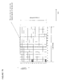
- FIG. 16 illustrates the OFDM symbol assignments for various PSS/SSS transmission timings with regard to the center resource blocks.
- FIG. 17 illustrates a neighbor cell list for identifying the PSS/SSS timing transmissions for a plurality of remote radio heads.
- FIG. 18 is a look-up table for identifying PSS/SSS timing transmissions as a function of the cell ID.
- FIG. 19 illustrates a modulo-four determination of the PSS/SSS timing transmissions as a function of the cell ID.
- the cellular communication systems disclosed herein enable an advantageous balance between power consumption and mobility performance with regard to discovery of inter-frequency cells in carrier aggregation.
- the disclosed systems and techniques may be applied to the discovery of small cells corresponding to remote radio heads.
- the serving base station itself may transmit a secondary component carrier that may be discovered as disclosed herein.
- the discovery techniques, of the present application apply to both the discovery of new cells as well as discovery of secondary component carriers from a serving base station.
- the discovery techniques involve the use of a novel beacon signal and/or the use of modified synchronization signals.
- the beacon signal embodiments will be addressed first
- a new beacon signal is provided for an inter-frequency carrier or secondary component carrier that is time synchronized with a primary or reference carrier.
- the beacon signal may be a new type of pilot signal or reference signal.
- the reference carrier may be the primary component carrier in carrier aggregation operations.
- the user equipment can omit the conventional cell search. Instead, the user equipment can identify neighbor cells with one attempt or at most a few attempts of receiving the beacon signals. As a result, the power consumption for cell identification can be reduced.
- the beacon signal transmission rate can be relatively slow so as to further reduce the power consumption in that the UE will need to make measurements at a correspondingly slower pace. Since the time synchronization with the reference carrier is used for cell identification, no degradation may be observed if the reference carrier mobility performance is maintained.
- the radio communication system (which may also be denoted as a mobile communication system) of FIG. 1 includes a base station 200 and a user equipment (UE) 100 .
- the base station communicates with the user equipment utilizing a primary carrier in a macro cell 50 , wherein the base station provide a radio communication service for the user equipment using the primary carrier.
- the primary carrier may be called a primary component carrier.
- the base station has a remote radio head 500 , which provides a radio communication service utilizing a secondary carrier for the user equipment at a small cell 51 , which is within the macro cell.
- the small cell may be denoted as a hot spot cell.
- one remote radio head is illustrated, but the base station may have more than one remote radio head within the macro cell.
- the secondary carrier is conventionally referred to as a secondary component carrier within the field of carrier aggregation.
- a link between the remote radio head and the user equipment is called a secondary carrier link 710 whereas a link between the base station and the user equipment is called a primary carrier link 720 .
- a link between the base station and the remote radio head is called an RRH link 730 .
- the base station is connected to a higher layer station, for example, an access gateway apparatus 300 in a backhaul connection 740 .
- the access gateway apparatus is connected to a core network (CN) 400 .
- the access gateway may be also referred to as MME/SGW (Mobility Management Entity/Serving Gateway).
- the base station communicates with the user equipment in the macro cell utilizing Evolve UTRA and UTRAN (alias: Long Term Evolution (LTE)) in the primary carrier link and in the secondary carrier link via the remote radio head.
- LTE Long Term Evolution
- the radio communication system may be an LTE Advanced system, a WiMAX, a WiFi system, or any other suitable system.
- the radio resource allocation in the communication links may be Frequency Division Duplex (FDD), Time Division Duplex (TDD), or a combination of these radio resource allocations.
- the primary carrier is 2 GHz whereas the secondary carrier is 3.5 GHz. These frequencies are just examples, and other carrier frequencies may be utilized in alternative embodiments.
- the base station communicates with the user equipment utilizing carrier aggregation operations, i.e. the base station communicates with the user equipment utilizing both the primary carrier link and the secondary carrier link simultaneously.
- the base station may communicates with the user equipment utilizing the carrier aggregation operations while the user equipment is located within the small cell 51 , whereas the base station may communicates with the user equipment utilizing only the primary carrier link if the user equipment is within the remainder of the macro cell outside of the small cell.
- the secondary carrier Since the base station is controlling the remote radio head, the secondary carrier is time synchronized with the primary carrier. Thus, signals transmitted in the secondary carrier are time synchronized with those in the primary carrier. This synchronization is exploited as discussed further herein to provide discovery techniques that achieve an advantageous balance between mobility performance and power consumption.
- FIG. 2 another system architecture is illustrated in FIG. 2 .
- the base station does not have a remote radio head 500 but instead transmits signals in the secondary carrier using the same antenna (or another co-located antenna or antenna array) as used to transmit the primary carrier.
- the small cell may be smaller than the macro cell as illustrated in FIG. 2 , or it may be the same size as the macro cell.
- This embodiment can apply to the carrier aggregation operations addressed in Annex J of TS 36.300, V10.4.0, 2011-06.
- the primary carrier is the same as a Release 8 LTE carrier
- the secondary carrier is a new type of carrier that is different from the Release 8 LTE carrier, at least in terms of cell search and measurements.
- the primary carrier is a Release 8 LTE carrier
- the primary carrier has common reference signals (CRS) and primary/secondary synchronization signals (PSS/SSS).
- the novel secondary carrier disclosed herein need not include common reference signals nor primary/secondary synchronization signals.
- the secondary carrier has beacon signals. Detailed explanation of these novel beacon signals are described herein.
- the primary carrier may be the same as a Release 9 or a Release 10 LTE carrier, instead of a Release 8 LTE carrier.
- the secondary carrier may be a carrier which has not only CRS and PSS/SSS, but also the beacon signals.
- the secondary carrier may be backward compatible for user equipment that does not support receiving the beacon signals but will still enable the disclosed novel user equipment that support receiving the beacon signals so as to reduce the power consumption for the cell search and measurements in these modified UEs.
- the beacon signals can be transmitted in a Release 8 LTE carrier, in a Release 9 LIE carrier, or in a Release 10 LTE carrier.
- the beacon signals may be transmitted in Multi-Broadcast Single Frequency Network (MBSFN) sub-frames, where CRS is transmitted only in the first OFDM symbol, i.e. no CRS is transmitted in OFDM symbols other than the first OFDM symbol.
- MRSFN Multi-Broadcast Single Frequency Network
- the beacon signals may be transmitted in the OFDM symbols other than the first OFDM symbol, as illustrated in FIG. 2A , in which a physical signal frame format for one sub-frame and one resource block in LTE is shown. As seen in FIG. 2A , the first OFDM symbol is reserved for the CRS signal.
- the beacon signals may be transmitted using resource elements that do not constitute an entire resource block as illustrated in FIG. 2B (with the first OFDM symbol again being reserved for the CRS transmission).
- the retention of the CRS signal enables backward compatibility with conventional Release 8 UEs.
- the user equipment makes cell search and measurements in a conventional fashion.
- the same mobility performance as realized in Release 8 LTE can be achieved for the primary carrier.
- the search and measurement for the secondary carrier using the beacon signals will be discussed further below.
- FIG. 3 illustrates another example radio communication system, in which a base station 200 has four remote radio heads, such as a remote radio head 500 A, a remote radio head 500 B, a remote radio head 500 C, and a remote radio head 500 D.
- Each remote radio head transmits its own beacon signals in downlink in the secondary carrier, and a user equipment 100 monitors the beacon signals for cell search and measurements in the secondary carrier.
- FIG. 4 illustrates an example of the radio resources for the beacon signals.
- a frequency resource #3 is assigned as the frequency radio resource for the beacon signals whereas a time resource #6 is assigned as time radio resource.
- each remote radio head has its own code resource.
- the code resource #0, #1, #2, and #3 may be assigned to remote radio heads 500 A, 500 B, 500 C, and 500 D, respectively.
- the code resource may be a combination of a Constant Amplitude Zero Autocorrelation (CAZAC) sequence (or Zadoff-Chu sequence) and cyclic shift as discussed below.
- CAZAC Constant Amplitude Zero Autocorrelation
- each remote radio head has its own frequency resource as opposed to assigning a unique code resource.
- the beacon signals for the remote radio heads may be multiplexed in the frequency domain instead of the code domain.
- time synchronization is achieved for all the secondary carrier links, i.e. the transmission timing of the time slots for all the secondary links are aligned with each other, as illustrated in FIG. 5 .
- Each time slot may correspond to a sub-frame or a radio frame.
- the remote radio heads will typically each have a different range to the UE as compared to the other remote radio heads, their beacon signals will arrive with correspondingly different propagation delays at the UE.
- the reception timing of the secondary carrier links at the UE will be asynchronous as shown in FIG. 6 .
- FIG. 6 shows the primary carrier link timing as received at the UE as well as the as-received-at-the-UE timing for a secondary carrier link 710 A, a secondary carrier link 710 B, a secondary carrier link 710 C, and a secondary carrier link 710 D.
- These secondary carrier links correspond, respectively, to remote radio heads 500 A, 500 B, 500 C, and 500 D of FIG. 3 .
- the secondary carriers were all time synchronized with the primary carrier at the remote radio heads, the different propagation delays causes corresponding timing offsets for the received secondary carriers as shown in FIG. 6 .
- the asynchronous reception resulting from these different propagation delays may be addressed in several fashions. For example, accommodation of these delays may be achieved through an appropriate cyclic prefix length as discussed further below with regard to FIG. 7 .
- the different propagation delays between the base station and the remote radio heads also causes offsets in secondary timing with regard to the primary carrier.
- These different propagation delays may be accommodated by utilizing RRH link 730 ( FIG. 1 ).
- the base station can measure the transfer delay for each RRH link and adjust the transmission timings for the corresponding remote radio heads so that the transmission timings are aligned with each other. More specifically, the base station may adjust the transmission timings for the secondary carriers so that the transmission timings are aligned with a transmission timing of the primary carrier.
- the transfer delay in the RRH link may depend on cable length in the RRH link and a processing delay in the remote radio head or in the base station.
- the transmission timings in the secondary carrier may be aligned with the downlink frame timing in the primary carrier. More specifically, the transmission timings in the secondary carrier may be aligned with the start of the downlink frame timing in the primary carrier.
- the downlink frame timing may be specified by the start of the downlink radio frame timing and its downlink radio frame number or its downlink sub-frame number.
- the radio base station may identify the downlink radio frame number or sub-frame number through control signaling to the UE such as through the use of broadcast channels, dedicated control signaling and other suitable control signals.
- uplink frame timing may be utilized for the time synchronization.
- time synchronization techniques may be utilized to achieve the time synchronization for the secondary carrier links.
- GPS may be used for the time synchronization.
- the frame timing of the secondary carrier links is specified so that the frame timings of the secondary carrier links are all time synchronized with each other.
- the time synchronization is achieved with reference to the primary carrier.
- the reception timing of the secondary carrier links at the UE is based on the primary carrier timing.
- the user equipment assumes that the frame timing for the secondary links are aligned with a corresponding frame timing in the primary carrier so that the UE receives the beacon signals according to this assumed timing.
- the user equipment has only to decode/demodulate the beacon signals transmitted by multiple remote radio heads in the predetermined radio resources as discussed with regard to FIG. 4 , and therefore power consumption for the cell discovery utilizing the beacon signals can be minimized. More detailed examples are shown below.
- the user equipment does not have to achieve time synchronization with multiple remote radio heads using conventional CRS and PSS/SSS signals because it can achieve the time synchronization by decoding the beacon signals, which are time-synchronized with the signals in the primary carrier link.
- the complexity for cell identification and measurements and associated power consumption are both reduced as compared to the use of conventional PSS/SSS techniques.
- the remote radio heads are shown transmitting their beacon signals to the user equipment.
- a common time and frequency domain resource may be used for all the beacon signals such that the beacon signals are differentiated through the use of different code resources.
- a different code may be assigned to each beacon signal.
- the code resource #0, #1, #2, and #3 of FIG. 4 may be assigned to remote radio heads 500 A, 500 B, 500 C and 500 D, respectively.
- a CAZAC (Constant Amplitude Zero AutoCorrelation) sequence may be used for each code. More specifically, Zadoff-Chu sequences may be used for the codes. Alternatively, Walsh sequences may be used for the codes.
- orthogonal sequences may be used for the codes.
- the code sequences for the various cells may each be partially orthogonal the other code sequences.
- some code sequence pairs may be orthogonal with each other, but others may not be orthogonal with each other.
- the code sequences do not interfere with each other.
- pilot pollution problems can be avoided, even when the beacon signals transmitted by a plurality of remote radio heads collide with each other upon reception at the UE.
- the power consumption for cell search and measurements can be reduced because the SIR for the beacon signals can be improved by avoiding pilot pollution problems.
- the beacon signal may have a physical layer format as illustrated in FIG. 7 .
- the beacon signal includes a cyclic prefix, a sequence part, and a guard period.
- the guard period may also be denoted as a blank part.
- the sequence part may comprise a CAZAC code.
- the user equipment may have a receiving window as illustrated in FIG. 8 .
- the received beacon signals from different remote radio heads are not time aligned with each other upon reception at UE 100 due to their different propagation delays. So long as these propagation delays are smaller than the cyclic prefix length, the user equipment can accurately demodulate and decode all the beacon signals.
- the user equipment may align the receiving window based on a timing of received signals in the primary carrier as shown in FIG. 8 .
- the received signals may be at least one of common reference signals, PSS/SSS, and other suitable signals.
- the user equipment may decide the position of the receiving window based on the timing of the received signals in the primary carrier and a time shift as illustrated in FIG. 8A .
- the base station may communicate the appropriate time shift amount to the UE using control signaling.
- the user equipment may obtain delay profiles for the beacon signals transmitted by each remote radio head as illustrated in FIG. 9 .
- the delay profiles for the beacon signals transmitted from each remote radio head may be shifted due to a cyclic shift of the Zadoff-Chu sequence, as illustrated in FIG. 9 .
- the cyclic shift for remote radio head 500 A is assumed to zero.
- the user equipment can easily make cell search and measurements for delay and received power level of the beacon signal for each remote radio head (or equivalently, for each small cell) in the secondary carrier.
- UE complexity for cell search and measurements in the second carrier can be reduced.
- the cyclic shift may be adjusted based on a range between the remote radio head and the base station (and/or to a size of the corresponding small cell).
- the cyclic shift may be adjusted based on a cell range to the base station (size of the macro cell).
- the cell range is large, it can be assumed that the remote radio heads in such a large cell are also similarly widely distributed, which leads to a corresponding large spread of delays for the received secondary carriers at the UE.
- the cyclic shift difference may be made relatively large in such a large cell.
- the macro cell is relatively small, the propagation delay spread for the beacon signals upon reception at the UE is also relatively small.
- the base station may notify the user equipment 100 of the cyclic shift for each remote radio head using control signaling.
- the control signaling may be transmitted in broadcast channels or in RRC signaling in the primary carrier.
- the physical random access channel (PRACH) or a physical channel similar to PRACH may be used for the beacon signals.
- PRACH is defined as a LTE physical channel in TS 36.211, V10.2.0, 2011-06.
- the remote radio head transmits signals similar to a random-access-preamble in the predetermined radio resource.
- the random access preamble may be assigned uniquely to the remote radio head by the base station.
- the base station identifies the random access preambles to the user equipment using appropriate control signaling.
- the beacon signals may be transmitted relatively infrequently. For example, the beacon signals may be transmitted once per second. Since time synchronization in the secondary carrier links is achieved by utilizing the primary carrier timing, the beacon signals do not have to be transmitted frequently. As a result, the user equipment has only to decode/demodulate the beacon signals according to the relatively infrequent transmission rate (e.g., once per second). Therefore the power consumption for the cell search and measurements can be minimized. Furthermore, the beacon signals are transmitted much less frequently than the common reference signals (CRS) or the synchronization signals (PSS/SSS) in LTE, and therefore power consumption at the network side (at the remote radio bead 500 ) can be reduced when no data is transmitted in the secondary carrier.
- CRS common reference signals
- PSS/SSS synchronization signals
- the beacon signal transmission period (i.e, the interval between consecutive beacon signal transmissions) may be very large, e.g. 1 or 2 seconds, or may be reasonably large, e.g. 100 milliseconds or 200 milliseconds. If the periodicity is very large, the power consumption for measurements and the interference issues can be reduced significantly, but the user equipment may need more time to detect neighbor remote radio heads and make measurements for them because it needs some measurement samples to achieve good accuracy. As a result, latency of mobility procedures may be increased, which adversely affects mobility performance. If the periodicity is reduced, the power consumption for cell search and measurements is increased the latency will be decreased. So, the periodicity of the beacon signals can be optimized based on the above aspects, such as power consumption for cell search measurements, latency of mobility procedures and the like.
- the periodicity of the beacon signals may be network configurable and the base station may inform the user equipment of the periodicity through control signaling.
- the user equipment does not support data transmissions/receptions simultaneously with decoding/demodulating the beacon signals in the secondary carrier.
- the base station may consider this configuration of the user equipment in its scheduling for the secondary carrier link. For example, the base station may avoid assigning radio resource to the user equipment in the secondary carrier during the times when the beacon signals are transmitted.
- the beacon signal may be denoted as an “extension carrier reference signal” or as an “extension carrier synchronization signal.”
- the beacon signals may be distributed in the frequency domain so that signal strength fluctuation due to Rayleigh fading may be suppressed and more accurate measurements for the radio link quality may be achieved.
- the base station may notify the user equipment of beacon signal information for each remote radio head.
- the information may be included in the control signaling, which notifies the user equipment of secondary carrier measurement information.
- suitable beacon signal information includes
- the above information is specified for each remote radio head, and therefore may be included in a neighbor cell list for the remote radio head.
- a remote radio head may correspond to a cell in the secondary carrier.
- the above beacon signal information may be signaled by broadcast information in the primary carrier link or by dedicated signaling in the primary carrier link.
- one time domain resource and frequency domain resource are specified for the beacon signals as illustrated in FIG. 4 .
- more than one time domain resource or more than one frequency domain resource may be configured for the remote radio heads. For example, if there are many remote radio heads, the number of code-domain resources may not be sufficient and more than one time domain resource or more than frequency domain resource may need to be used.
- FIG. 9A a base station 200 A has three remote radio heads 500 AA/ 500 AB/ 500 AC, and another base station 200 B has three remote radio heads 500 BA/ 500 BB/ 500 BC. It is assumed for this embodiment that the primary carrier signals transmitted by the base stations are time synchronized with each other.
- carrier aggregation operations if the user equipment communicates with the base station 200 A in the primary carrier, then that user equipment does not communicate with remote radio heads in the neighboring cells (e.g, remote radio heads 500 BA/ 500 BB/ 500 BC).
- remote radio heads 500 BA/ 500 BB/ 500 BC e.g., remote radio heads 500 BA/ 500 BB/ 500 BC.
- a serving base station corresponds to a base station which currently communicates with the user equipment 100 .
- carrier aggregation is only performed with the secondary component carriers corresponding to small cells (and their remote radio heads) within the serving base station's macro cell.
- the user equipment should communicate with a remote radio head which has the best radio link quality in the secondary carrier. Otherwise, the secondary carrier having the better radio link quality may interfere with a lower quality secondary carrier that is being currently used for carrier aggregation. In this sense, the user equipment may make cell search and measurements for remote radio heads that belong to neighbor base stations/macro cells. Based upon these measurements, the user equipment or the base station may release the secondary carrier link with the serving remote radio head so that it does not interfere with a remote radio head having a secondary carrier with better radio link quality as compared to the serving remote radio head.
- the base station If the user equipment makes measurements for remote radio heads which belongs to the serving base station and also for remote radio heads belonging to neighbor base stations, the base station notifies the user equipment of beacon signal information for the remote radio heads in the neighboring cells analogously as described above.
- the information may be included in a neighbor cell list for the secondary carrier.
- remote radio head 500 belongs to base station 200 such that the remote radio head and the base station may be considered to comprise a single apparatus. Therefore, communications between the base station and the remote radio head are omitted in FIG. 10 .
- the base station communicates with the user equipment utilizing only the primary carrier initially such that the secondary carrier link is established subsequent to the primary carrier communication.
- the base station communicates with the user equipment in the primary carrier link.
- the base station transmits downlink data to the user equipment and receives uplink data from the user equipment over the primary carrier link.
- the downlink and uplink data may correspond to sending/receiving e-mails, browsing web sites, downloading files, uploading files and the like. This data flow may be referred to as “traffic data.”
- a step S 802 a the base station transmits control signaling to the user equipment over the primary carrier link to command the user equipment 100 to make measurements for the secondary carriers. Pursuant to this command, the user equipment makes the measurements in a step 802 b .
- a step 802 c the user equipment transmits a measurement report to the base station 200 in the primary carrier link 720 .
- the measurement report identifies the remote radio head having the best downlink (DL) radio link quality.
- the control signaling in step S 801 may include information for the measurements.
- the control signaling may include at least one of carrier frequency for the secondary carriers, bandwidth of the secondary carrier links, identification numbers for the remote radio heads, measurement quantity, beacon signal information, and so on.
- the measurement quantity information may include an indicator of received power for the beacon signals or received quality of the beacon signals.
- the beacon signal information may identify the radio resource allocation for the beacon signals. More specifically, the information may include beacon signal periodicity, the frequency-domain resource allocation, the time-domain resource allocation, the code-resource allocation, and so on.
- the transmission power for the beacon signals may be included as well.
- rules for sending measurement reports to the base station 200 may also be included in the control signaling transmitted in step S 802 a .
- the rules may be criteria that are specified for Release 8 or Release 9 or Release 10 LTE, such as Event A1, A2, A3, A4, A5, A6 and the like. These rules are specified in TS 36.331, V10.2.0, 2011-06. Threshold value or Layer-3 filtering coefficient as well as time-to-trigger may also be identified through the control signaling.
- cell selection/reselection information may also be communicated through the control signaling. For example, idle-mode measurement information may also be included in the control signaling.
- the control signaling may be transmitted in the dedicated control signaling or in the broadcast information.
- the control signaling in step S 802 a may include an indicator whether or not a secondary carrier for the beacon signals is available in the serving base station's macro cell.
- the control signaling may be transmitted in step S 801 instead of step S 802 a.
- the user equipment measures the DL radio link quality in the secondary carrier by utilizing the secondary carrier's beacon signals.
- the DL radio link quality may be the received beacon signal power.
- the DL radio link quality may be the received beacon signal quality.
- the DL radio link quality may be based on the signal-to-interference ratio of the received beacon signal.
- the beacon signals format and measurements may be the same as described above.
- a step S 803 a the base station transmits control signaling to the user equipment over the primary carrier link to command the user equipment to establish the secondary carrier link with a particular remote radio head.
- this remote radio head is the one which has the best DL radio link quality identified in the measurement report of step 802 c .
- the control signaling of step S 803 a may include at least one of the following parameters:
- a step S 803 b the user equipment transmits a preamble to the remote radio head in the secondary carrier to establish the secondary carrier link between the user equipment and the remote radio head.
- the preamble may be a random access preamble.
- the preamble may be a pre-assigned dedicated preamble.
- the pre-assigned access signaling may be transmitted to the user equipment by the base station 200 in step S 803 a .
- the remote radio head transmits response signals to the preamble transmitted in step S 803 b . As a result, the secondary carrier link is established.
- step S 803 d the user equipment transmits control signaling to the base station over the primary carrier link and notifies the base station that the secondary carrier link has been successfully established.
- step S 803 d can be omitted.
- this control signaling may be transmitted to the base station via the remote radio head in the secondary carrier.
- a step S 804 a the base station communicates with the user equipment over the primary carrier link.
- Step S 804 a is thus the same as step S 801 .
- this communication with the base station may be conducted continuously during the steps shown in FIG. 10 .
- the remote radio head 500 communicates with the user equipment over the secondary carrier link. In this fashion, the user equipment communicates with the base station using carrier aggregation.
- the steps shown in FIG. 10 may be described in terms of the remote radio head acts as follows.
- the remote radio head operation comprises transmitting beacon signals in the secondary carrier (step S 802 b ).
- the user equipment operation includes making cell search and measurements using beacon signals transmitted by the remote radio head (steps S 802 a / 802 b / 802 c ), establishing the secondary carrier link with the remote radio heads 500 (steps S 803 a / 803 b / 803 c / 803 d ), and communicating with the base station using carrier aggregation (step S 804 a / 804 b ).
- the remote radio head may omit the beacon signal transmissions if no secondary carrier links exist, i.e. when there is no data to be transmitted in the secondary carrier.
- the remote radio head may start transmitting the beacon signals in the secondary carrier at the beginning of step S 802 b .
- the remote radio head can reduce power consumption when here is no data to be transmitted in the secondary carrier.
- FIG. 11 An example call flow for such a handoff is shown in FIG. 11 .
- the source/target remote radio heads 500 belong to the base station 200 .
- these radio heads constructively form a single apparatus with the base such that communications between the base station and the remote radio heads are omitted in FIG. 11 .
- the base station initially communicates with the user equipment utilizing the primary carrier in a step S 901 a and also by using the secondary carrier via the source remote radio head in a step S 901 b .
- the base station communicates with the user equipment using carrier aggregation operations in steps S 901 a and S 901 b .
- Steps S 901 a and S 90 b may be the same as steps 804 a and S 804 b , respectively, as discussed with regard to FIG. 10 .
- step S 902 a the base station transmits control signaling to the user equipment over the primary carrier link to command the user equipment 100 to make measurements of the secondary carrier.
- Step S 902 a thus corresponds to step S 802 a of FIG. 10 . If the control signaling in step S 902 a has already been transmitted to the user equipment such as in step S 901 a , this step may be omitted.
- the user equipment conducts the measurements for the secondary carrier.
- the user equipment conducts such measurements by determining the DL radio link quality for the serving remote radio head as well as for the target remote radio head(s).
- the DL radio link quality may be determined from the received beacon signals.
- the DL radio link quality may be at least one of received power of the beacon signals, received quality of the beacon signals, path loss, signal-to-interference ratio (SIR) of the beacon signals, channel state information, channel quality indicator, received signal strength indicator of the beacon signals, and other suitable parameters determined from the secondary carrier.
- SIR signal-to-interference ratio
- the user equipment determines whether or not a target remote radio head has a better DL radio link quality than the serving remote radio head. For example, the user equipment may be closer to the target remote radio head and further away from the serving radio head.
- FIG. 12 is a flow chart for the handoff process call flow shown in FIG. 11 .
- the user equipment measures the DL radio link, quality as discussed with regard to step 902 b .
- the user equipment determines whether a target remote radio head is closer than the serving remote radio head. For example, if the radio link quality of the neighbor (or target) remote radio head is higher than that of the serving remote radio head, it may be assumed that the neighbor remote radio head is closer to the user equipment than the serving remote radio head.
- RLQ Neighbor is the radio link quality of the neighbor remote radio head and RLQS erving is the radio link quality of the serving remote radio head.
- This equation is analogous to Event A3 or A6, which is specified in TS 36.331, V10.2.0, 2011-06. Other events such as Events A1, A2, A4, or A5 may be utilized in alternative embodiments.
- Step S 1002 If the neighbor remote radio head is determined to be closer than the serving remote radio head (a YES result for a step S 1002 ), the user equipment transmits a measurement report to the base station in a step S 1003 so as to notify the base station of this determination. Conversely, if the result of step S 1002 is a NO (where the neighbor remote radio head is not closer), the user equipment does not transmit the measurement report to the base station. Steps S 1001 and S 1002 of FIG. 12 thus correspond to step S 902 b in FIG. 11 .
- a step S 902 c the user equipment transmits a measurement report to the base station regarding the determination that the target remote radio head has a sufficiently higher radio link quality than that for the serving remote radio head.
- Step S 902 c in FIG. 11 thus corresponds to step S 1003 of FIG. 12 .
- the base station in a step S 902 d determines that the user equipment should handover to the neighbor remote radio head (the target remote radio head) in the secondary carrier.
- the base station transmits control signaling to the user equipment to order the user equipment to handover to the target remote radio head.
- the control signaling may be denoted as a “handover command.”
- the handover command may include connection information for the secondary carrier link 710 .
- the connection information may include at least one of a configuration measurement for the secondary carrier link, mobility control information for the secondary carrier link, radio resource control information for the secondary carrier link, and other suitable parameters.
- the radio resource control information for the secondary carrier link may include at least one of a MAC layer configuration for the secondary carrier link, a physical layer configuration in the secondary carrier link, and other suitable information.
- the parameters discussed with regard to step S 803 a of FIG. 10 may be included in the radio resource control information for the secondary carrier link in step S 903 a.
- a step S 903 b the user equipment transmits a preamble to the remote radio head in the secondary carrier to establish a connection between the user equipment 100 and the target remote radio head.
- the preamble may be a random access preamble.
- the preamble may be a pre-assigned dedicated preamble.
- the pre-assigned access signaling information may be transmitted to the user equipment by the base station in step S 903 a .
- the target remote radio head 500 transmits response signals to the UE in response to the preamble transmitted in step S 9036 . As a result, the secondary carrier link is established between the user equipment and the target remote radio head 500 .
- a step S 903 d the user equipment transmits control signaling to the base station to notify the base station that the handover to the target remote radio head has been successfully completed.
- the control signaling may be transmitted to the base station via the target remote radio head in the secondary carrier such that step S 903 d is omitted.
- a step S 904 a the base station communicates with the user equipment over the primary carrier link.
- Step S 904 a is thus the same as step S 901 a such that the communication over the primary carrier may be conducted continuously during the call flow of FIG. 11 .
- the remote radio head communicates with the user equipment in the secondary carrier link. In this fashion, the user equipment communicates with the base station using carrier aggregation operations.
- the call flow shown in FIG. 11 may be described in terms of the user equipment operation.
- the acts by the user equipment comprise making measurements for the secondary carrier link (steps S 902 a to S 902 b ) using the beacon signals transmitted by the serving remote radio head and neighbor remote radio heads, transmitting a measurement report to the base station (step S 902 c ), and conducting handover to the target remote radio head (steps S 903 a to S 903 d ).
- FIG. 13 illustrates a functional block diagram of the base station whereas FIG. 14 illustrates a functional diagram of the user equipment.
- the user equipment communicates with the base station utilizing carrier aggregation of the primary carrier and the secondary carrier.
- the remote radio head may be regarded as an antenna device or a radio device which belongs to the base station, the remote radio head is included as part of the base station in FIG. 13 . It will be appreciated, however, that the base station of FIG. 13 is just an embodiment such that alternative configurations may be implemented.
- the base station of FIG. 13 includes a secondary carrier communication section 202 , a primary carrier communication section 204 , a control section 206 , a backhaul communication section 208 , and a remote radio head 500 .
- Secondary carrier communication section 202 , primary carrier communication section 204 , control section 206 , and backhaul communication section 208 are all operatively coupled to each other.
- Secondary carrier communication section 202 is also operatively coupled to remote radio head 500 .
- the secondary carrier communication section communicates with the user equipment utilizing the secondary carrier link via the remote radio head.
- the secondary carrier communication section controls the transmission of the beacon signals in the secondary carrier.
- the beacon signals are transmitted to the user equipment via the remote radio head.
- secondary carrier communication section 202 may have a transmission and reception unit 2021 and a beacon signal transmission unit 2022 .
- the transmission and reception unit communicates with the user equipment over the secondary carrier link 710 , i.e. it transmits user data and control signaling to the user equipment and vice versa via the remote radio head in the secondary carrier link.
- the beacon signal transmission unit transmits the beacon signals via the remote radio head in the secondary carrier link. The details of the beacon signals are the same as the ones described above, and therefore are omitted here.
- the primary carrier communication section communicates with the user equipment utilizing the primary carrier link.
- a remote radio head may be used in the primary carrier link analogous to secondary carrier link.
- the primary carrier communication section transmits control signaling for the secondary carrier link to the user equipment and receives control signaling for the secondary carrier link from the user equipment.
- This control signaling may be the same as described in FIGS. 10 and 11 .
- a control section 206 controls the primary carrier link and the secondary carrier link. More specifically, the control section conducts the handover procedures and the establishment procedures for the secondary carrier link discussed with regard to FIGS. 10 and 11 .
- control section 206 may conduct other radio link connection control for the secondary carrier link.
- such other radio link connection control may be at least one of configuring/re-configuring/re-establishing/releasing the secondary carrier link.
- a backhaul communication section 208 has a backhaul link which is connected to the core network.
- the backhaul communication section transmits downlink data to the secondary carrier communication section and to the primary carrier communication section.
- the backhaul communication section receives uplink data from the secondary carrier communication section and from the primary carrier communication section.
- the downlink data is transmitted from the core network 400
- the uplink data is transmitted to the core network 400 .
- the user equipment has a secondary carrier communication section 102 and a primary carrier communication section 104 .
- Secondary carrier communication section 102 and primary carrier communication section 104 are connected to each other.
- Secondary carrier communication section 102 communicates with the base station via the remote radio head utilizing the secondary carrier link.
- secondary carrier communication section 102 makes cell search and measurements for the secondary carrier utilizing the beacon signals transmitted by the base station via the remote radio head in the secondary carrier as discussed above.
- secondary carrier communication section 102 may have a transmission and reception unit 1021 and a beacon signal reception unit 1022 .
- Transmission and reception unit 1021 communicates with the base station in secondary carrier link 710 , i.e. it transmits user data and control signaling to the base station and vice versa in secondary carrier link 710 .
- the beacon signal reception unit 1022 receives the beacon signals in the secondary carrier link 710 . More specifically, the beacon signal reception 1022 makes cell search and measurements for the secondary carrier utilizing the beacon signals as discussed above.
- the primary carrier communication section 104 communicates with the base station utilizing the primary carrier link 720 . Furthermore, the primary carrier communication section 102 receives control signaling for the secondary carrier link 710 from the base station 200 and transmits control signaling for the secondary carrier link 710 to the base station 200 . For example, the primary carrier communication section 102 may transmit measurement reports for the secondary carrier link 710 to the base station 200 in the primary carrier link 720 . In other examples, the primary carrier communication section 102 may receive a handover command for the secondary carrier link 710 , which is transmitted in the primary carrier link 720 as discussed with regard to FIGS. 10 and 11 .
- a remote radio head is utilized for the secondary carrier but it will be appreciated that other types of network nodes for carrier aggregation operations may be utilized.
- any suitable network node that communicates with the user equipment using radio signals may be utilized instead of the remote radio head in alternative embodiments.
- a remote radio head may be replaced with an antenna device or an antenna/radio device in some other embodiments.
- various kinds of devices may co-exist in the macro cell.
- the serving cell can notify the user equipment of the transmission timing of PSS/SSS for each cell in the secondary component carrier. Because other signals in the time frame and frequency resource for the modified PSS/SSS are not transmitted, the pilot pollution problems can be avoided for PSS/SSS. As a result, the user equipment can conduct cell search in the secondary component carrier in high signal-to-interference (SIR) conditions, and therefore quickly identify cells with low power consumptions.
- SIR signal-to-interference
- the user equipment can avoid inter-cell interference for the cell identification in the secondary carrier and associated low SIR conditions.
- the user equipment can significantly reduce time and battery consumption for the cell identification in the secondary carrier.
- FIGS. 1-2 System architectures for carrier aggregation using remote radio heads transmitting the modified PSS/SSS signals may be as described above with regard to FIGS. 1-2 .
- the primary carrier is the same as a Release 8 LTE carrier
- the secondary carrier is a new type carrier in terms of cell search and measurements.
- the secondary carrier has slightly-modified primary/secondary synchronization signals.
- the slightly-modified primary/secondary synchronization signals are denoted herein as modified PSS/SSS.
- the primary carrier may be the same as a Release 9 or Release 10 LTE carrier, instead of a Release 8 LTE carrier.
- FIG. 3A illustrates a macro cell with four remote radio heads 500 A, 500 B, 500 C, and 500 D. Each of these remote radio heads is configured to transmit the modified PSS/SSS signals.
- FIG. 15 illustrates an example of the radio resource allocation for the modified PSS/SSS for the remote radio heads of FIG. 3A .
- the modified PSS/SSS are transmitted in sub-frames #0 and #5 analogously to conventional PSS/SSS signal timing. In FIG. 15 , only the sub-frame #5 transmissions are shown but the same timing applies to sub-frame #0 transmissions.
- the modified PSS/SSS are the same as the Release 8 PSS/SSS, which is defined in TS 36.211, Section 6.11.1.
- the modified PSS/SSS are transmitted in the same frequency-domain radio resources as the Release 8 PSS/SSS.
- the modified PSS/SSS are transmitted in the center 6 resource blocks in a carrier.
- time-domain radio resource allocation for the modified PSS/SSS differs for the various remote radio heads.
- time-domain radio resource allocation for the modified PSS/SSS differs from conventional Release 8 PSS/SSS. More details of the time-domain resources are explained below.
- each remote radio head transmits modified PSS/SSS in its own transmission timing, which is different from the transmission timing for the remaining remote radio heads.
- the transmission timing of one remote radio head does not collide with that of another remote radio head.
- modified PSS/SSS transmitted by each remote radio head do not interfere with one another such that the user equipment can conduct cell search in high SIR conditions.
- Achieving a high SIR in cell search using the modified PSS/SSS is advantageous. For example, cell search is quickly conducted in high SIR conditions whereas cell search in low SIR conditions needs a lot of time. Therefore, the user equipment can reduce the power consumption for the cell search under high SIR conditions. In other words, transmitting the modified PSS/SSS in non-conflicting time-domain resources such that each cell has its own unique PSS/SSS transmission timing can improve received SIR of the modified PSS/SSS at the UE and as a result reduce power consumption.
- the use of conventional Release 8 PSS/SSS leads to degraded received SIR from the resulting pilot pollution.
- the user equipment can limit its cell search to only high-SIR scenarios so as to reduce power consumption but then area in which the user equipment can detect neighbor cells is reduced.
- the user equipment does not limit its search to high-SIR scenarios, the area in which the user equipment can detect neighbor cells is maintained but the power consumption increases.
- the use of the modified PSS/SSS disclosed herein does not degrade SIR.
- the user equipment can advantageously detect neighbor cells in a wide area with low power consumption.
- the modified PSS/SSS transmission timing for FIGS. 15 and 16 is:
- FIG. 16 shows some parts of resource elements in Sub-frame #5 and the center 6 resource blocks in which the modified PSS/SSS are transmitted.
- the remote radio head 500 A transmits the modified PSS/SSS in the same OFDM symbols as for conventional Release 8 PSS/SSS. That is, the remote radio head for a particular cell may transmit the modified PSS/SSS in the same transmission timing as the conventional PSS/SSS.
- the remote radio heads 500 B, 500 C, and 500 D transmit the modified PSS/SSS in OFDM symbols where cell-specific reference signals (CRS) are not transmitted. As a result, the modified PSS/SSS do not collide with CRS transmissions.
- CRS cell-specific reference signals
- the remote radio heads 500 A, 500 B, 500 C, and 500 D transmit the modified PSS/SSS in the sub-frames in which the Release 8 PSS/SSS are transmitted. Furthermore, only CRS are transmitted in resource elements other than the resource elements where the modified PSS/SSS are transmitted. That is, DL signals other than CRS and the modified PSS/SSS are DTXed in resource elements which consist of Sub-frames #0 and #5 and the center 6 resource blocks. As a result, signals transmitted by one remote radio head do not interfere with the modified PSS/SSS transmitted by other remote radio heads. It is noted that in case no CRS are transmitted in the secondary carrier (the additional carrier type), CRS would thus not be transmitted in the resource elements which consist of Sub-frame #0 and #5 and the center 6 resource blocks.
- the resource elements other than CRS and the modified PSS/SSS are DTXed in the resource elements which consist of Sub-frame #0/#5 and the center 6 resource blocks, the number of DTXed resource elements is not large and therefore overhead of the DTXed resource elements is not so large.
- guard period between OFDM symbols where one remote radio head transmits the modified PSS/SSS and those where another remote radio head transmits the modified PSS/SSS as illustrated in FIG. 16 .
- the OFDM symbols #3, #4, #7, #8, #11 correspond respectively to guard periods.
- the guard period can avoid interference between the modified PSS/SSS transmitted by remote radio heads, even when the modified PSS/SSS propagation delay for one remote radio head is different from that for another remote radio head. If the propagation-delay difference among cells is large, received power difference among cells is also large, and therefore a relatively small guard period, such as one-OFDM-symbol-length, may be sufficient to avoid inter-cell interference.
- the base station may notify the user equipment of transmission timing of the modified PSS/SSS for each remote radio head (each cell in the secondary carrier).
- the user equipment can identify DL transmission timing for the secondary carrier by utilizing the transmission timing and reception timing of the modified PSS/SSS.
- the base station may notify the user equipment of OFDM symbols of the modified PSS/SSS for each remote radio head (each cell in the secondary carrier).
- the base station 200 may notify the user equipment 100 of:
- the base station may notify the user equipment of the transmission timing of the modified PSS/SSS for each cell in the second carrier by utilizing the broadcast channel in the primary carrier.
- the transmission timing of the modified PSS/SSS for each cell in the second carrier may thus be included in system information transmitted in the primary carrier.
- the transmission timing may be included in a neighbor cell list transmitted in the primary carrier.
- the base station may notify the user equipment of the transmission timing of the modified PSS/SSS for each cell in the second carrier by utilizing Radio Resource Control (RRC) dedicated signaling in the primary carrier instead of the broadcast channels.
- RRC Radio Resource Control
- the RRC dedicated signaling may be called “signaling radio bearer” or “Dedicated Control Channel (DCCH)”.
- the base station may transmit neighbor cell list shown in FIG. 17 .
- the neighbor cell list may include the transmission timing of the modified PSS/SSS as an information element for each neighbor cell in addition to a physical cell ID and an individual cell offset. It is noted that the transmission timing is identified by the OFDM symbol index in FIG. 17 but other information to identify the transmission timing can also be used in the neighbor cell list.
- the number of cells identified in the neighbor cell list depends upon the number of remote radio heads deployed in the macro cell.
- an OFDM symbol index is utilized to identify the transmission timing of the modified PSS/SSS for each cell.
- another index such as a sub-frame number, a radio frame number, and the like, can also be utilized.
- a transmission timing of the modified PSS/SSS for each remote radio head may be determined by the cell identification number for each cell.
- the user equipment can identify the DL transmission timing for the secondary carrier by utilizing the transmission timing determined by the cell identification number and decoding results of the modified PSS/SSS.
- the transmission timing of the modified PSS/SSS for each remote radio head can be determined by the table shown in FIG. 18 that is indexed to the cell ID.
- the resulting look-up table defines a one-to-one mapping of the physical cell ID (cell identification number) and the transmission timing for the modified PSS/SSS in the corresponding remote radio head.
- the user equipment can identify the transmission timing of each remote radio head (each cell in the secondary carrier) by utilizing the cell identification number, which can be detected in decoding the modified PSS/SSS, and then utilizing the look-up table.
- the user equipment can thus identify DL radio frame timing of each remote radio head (each cell in the secondary carrier) by utilizing the cell identification number and the look-up table.
- the transmission timing of the modified PSS/SSS for each remote radio head can be determined applying a mathematical function on the cell ID such as the modulo 4 function of FIG. 19 .
- the transmission timing of the modified PSS/SSS is OFDM symbols #12 and #13.
- the user equipment can identify the transmission timing of each remote radio head (each cell in the secondary carrier) by utilizing the cell identification number, which can be detected in decoding the modified PSS/SSS and then applying the predetermined function on the cell ID.
- the base station may notify the user equipment 100 of whether the modified PSS/SSS should be utilized or not. If the modified PSS/SSS should not be utilized, the Release 8 PSS/SSS may be used in the secondary carrier. In this fashion, the remote radio heads are backward compatible with conventional Release 8 LTE UEs.
- the Release 8 PSS/SSS may be more useful than the modified PSS/SSS.
- the modified PSS/SSS may not provide any benefits because the DL radio frame timing is not synchronized among cells. That is, the modified PSS/SSS can be utilized in some deployment scenarios, but not in others. Therefore, it is useful to configure the modified PSS/SSS by the above control information, which the base station transmits to the user equipment.
- multiple remote radio heads in one base station is considered.
- multiple remote radio heads in more than one base station may be considered in some embodiments, as illustrated in FIG. 9A that was already discussed with regard to the beacon signal embodiment.
- the use equipment does not link to remote radio heads that are not in the serving base station's macro cell. Nevertheless, the user equipment should not use secondary carrier links that interfere with remote radio heads in the neighboring cell.
- the user equipment should conduct cell search and measurements for remote radio heads which belongs to neighbor base station to determine if any of their radio link qualities exceed that of the currently serving remote radio head. If such a link quality is identified, the base station may release the secondary carrier link with the serving remote radio head so that it does not interfere with the remote radio head which belongs to the neighbor base station.
- the base station notifies the user equipment of control information on the transmission timing of the modified PSS/SSS for these remote radio heads using the techniques as described above.
- the information for the neighboring cell's remote radio heads may be included in a neighbor cell list for the secondary carrier.
- step S 801 the base station 200 communicates with the user equipment 100 in the primary carrier link 720 .
- the base station transmits downlink data to the user equipment and receives uplink data from the user equipment in the primary carrier link as discussed previously.
- steps S 802 a to S 802 c the user equipment makes measurements for the secondary carrier and transmits a measurement report to the base station in the primary carrier link to notify the base station of the identification number of the remote radio head having the best DL radio link quality. More specifically, in step S 802 a , the base station transmits control signaling to the user equipment in the primary carrier link and orders for the user equipment to make measurements for the secondary carrier so that the user equipment detects a remote radio head with the best radio link quality in the secondary carrier.
- the control signaling may include information for the measurements.
- the control signaling may include at least one of carrier frequency for the secondary carrier, bandwidth of the secondary carrier link, identification number for remote radio heads, information on measurement quantity, information on the modified PSS/SSS transmitted by the remote radio heads and the like.
- the information on the modified PSS/SSS includes the transmission timing of the modified PSS/SSS as discussed above.
- the modified PSS/SSS information may include information on whether or not the modified PSS/SSS should be utilized. That is, the control signaling in the step S 802 a may include an indicator whether or not a carrier (secondary carrier) in which the modified PSS/SSS is transmitted is available in the base station's macro cell.
- a carrier secondary carrier
- rules for sending measurement reports to the base station may also be included in the information for the measurements.
- the rules may be criteria such as specified for Release 8, Release 9, or Release 10 LTE. These criteria include Event A1, A2, A3, A4, A5, A6 and the like.
- the rules are specified in TS 36.331, V10.2.0, 2011-06. Threshold value, a Layer-3 filtering coefficient, or a time-to-trigger may also be included in the information for the measurements.
- control signaling for cell selection/reselection may also be included in the information for the measurements. That is, control signaling for idle-mode measurements may also be included in the information for the measurements.
- the control signaling may be transmitted in the dedicated control signaling or in the broadcast information in the primary carrier.
- the control signaling may be transmitted in the step S 801 , instead of the step S 802 a.
- the user equipment 100 makes measurements for the DL radio link quality in the second carrier by utilizing the modified PSS/SSS and the reference signals in the secondary carrier.
- the user equipment measures the DL radio link quality by utilizing the reference signals.
- the reference signals may be cell-specific reference signals (CRS), channel state information reference signals (CSI-RS), or other reference signals.
- the DL radio link quality may be the received power of the reference signals.
- the DL radio link quality may be the received quality of the reference signals.
- the DL radio link quality may be the received signal-to-interference ratio of the reference signals.
- the user equipment may make measurements for the DL radio link quality by utilizing the modified PSS/SSS.
- step S 802 c the user equipment transmits to the base station a measurement report in the primary carrier link to notify the base station of the identification number for the remote radio head having the best DL radio link quality.
- the remaining steps in FIG. 10 are as described previously with regard to the beacon signal embodiment.
- the steps carried out by the network components for the modified PSS/SSS embodiment are also analogous to the beacon signal operations. The difference is that the modified PSS/SSS signals are transmitted and decoded instead of the beacon signals.
- Handoff to a target remote radio head from a source remote radio head in a PSS/SSS embodiment is also analogous to the handoff operation already described with regard to FIGS. 11 and 12 for the beacon signal embodiment.
- the previous description for the beacon signal embodiment may thus be used for the modified PSS/SSS signal embodiment by the replacement of the beacon signal by the modified PSS/SSS signals.
- the base station and user equipment configuration as discussed with regard to FIGS. 13 and 14 is also analogous to a modified PSS/SSS configuration.
- the difference is as shown in FIG. 13B for secondary communication section 202 , which may have a transmission and reception unit 2021 and a modified PSS/SSS transmission unit 2022 .
- the transmission and reception unit 2021 communicates with the user equipment in the secondary carrier link, i.e. it transmits user data and control signaling to the user equipment and vice versa via the remote radio head in the secondary carrier link.
- Modified PSS/SSS transmission unit 2022 transmits the modified PSS/SSS signals via the remote radio head in the secondary carrier link.
- Modified PSS/SSS transmission unit 2022 thus transmits the modified PSS/SSS signals according to this individual cell transmission timing assignment. For example, if the transmission timing of the modified PSS/SSS is determined by the physical cell ID, modified PSS/SSS transmission unit 2022 transmits the modified PSS/SSS at the transmission timing as determined from the physical cell ID.
- modified PSS/SSS transmission unit 2022 may decide the transmission timing of the modified PSS/SSS so that the transmission timing of the modified PSS/SSS does not collide with the transmission timing of the modified PSS/SSS for neighbor cells in the secondary carrier.
- modified PSS/SSS transmission unit 2022 may obtain information on the transmission timing of the PSS/SSS for the neighbor cells. The information can be exchanged in the base station or with neighbor base stations. If the information is exchanged with the neighbor base stations, such exchange may be conducted via secondary carrier communication section 202 , or the backhaul communication section 208 and the core network.
- the user equipment configuration is analogous to that already discussed with regard to the beacon signal embodiment illustrated in FIGS. 14 and 14A .
- secondary carrier communication section 102 of FIG. 14 makes cell search for the secondary carrier by utilizing the modified PSS/SSS and makes measurements for the secondary carrier by utilizing the reference signals.
- secondary carrier communication section 102 may have a transmission and reception unit 1021 and a cell search and measurement unit 1022 .
- cell search and measurement unit 1022 receives the modified PSS/SSS in the secondary carrier link. More specifically, cell search and measurement unit 1022 makes a cell search for the secondary carrier by utilizing the modified PSS/SSS. The cell search and measurement unit 1022 then makes measurements of the DL radio link quality by utilizing the reference signals.
- the cell search and measurement unit 1022 for a modified PSS/SSS embodiment makes a cell search based on the received modified PSS/SSS and the control information on the transmission timing of the modified PSS/SSS.
- cell search and measurement unit 1022 identifies DL radio frame timing for each cell by reception timing of the modified PSS/SSS and the information on the transmission timing of the modified PSS/SSS.
- cell search and measurement unit 1022 may identify the DL radio frame timing for each cell by the reception timing of the modified PSS/SSS and the transmission timing of the modified PSS/SSS as determined by the physical cell ID.
- the physical cell ID can be detected in decoding the modified PSS/SSS.
- cell search and measurement unit 1022 identifies the DL radio frame timing for each cell by reception timing of the modified PSS/SSS and the transmission timing of the modified PSS/SS which is indicated in the control information.
- the transmission timing may be indicated as illustrated in FIG. 17 .
- cell search and measurement unit 1022 identifies the DL radio frame timing for each cell by the reception timing of the modified PSS/SSS and the transmission timing of the modified PSS/SSS as determined by the look-up table and the physical cell ID.
- the physical cell ID can be detected in decoding the modified PSS/SSS.
- the modified PSS/SSS technique is not limited to remote radio head embodiments. Instead, the modified PSS/SSS technique may be applied to any suitable network node that communicates with the user equipment using a secondary carrier.
- the functions for the base station, the user equipment, and the remote radio head may be implemented by hardware, by a software module executed by a processor, or may further be implemented by a combination of both hardware and software.
- the software module may be arranged in a storing medium of an arbitrary format such as RAM (Random Access Memory), a flash memory, ROM (Read Only Memory), EPROM (Erasable Programmable ROM), EEPROM (Electronically Erasable and Programmable ROM), a register, a hard disk, a removable disk, and CD-ROM.
- Such a storing medium is connected to the processor so that the processor can write and read information into and from the storing medium.
- a storing medium may also be accumulated in the processor.
- Such a storing medium and processor may be arranged in ASIC.
- Such ASIC may be arranged in the base station apparatus, the user equipment, and the remote radio head.
- As a discrete component, such a storing medium and processor may be arranged, in the base station, the user equipment, and the remote radio head.
Landscapes
- Engineering & Computer Science (AREA)
- Signal Processing (AREA)
- Computer Networks & Wireless Communication (AREA)
- Computer Security & Cryptography (AREA)
- Quality & Reliability (AREA)
- Mobile Radio Communication Systems (AREA)
Priority Applications (1)
| Application Number | Priority Date | Filing Date | Title |
|---|---|---|---|
| US14/344,989 US9497693B2 (en) | 2011-09-16 | 2012-09-14 | Extension carrier discovery for carrier aggregation |
Applications Claiming Priority (5)
| Application Number | Priority Date | Filing Date | Title |
|---|---|---|---|
| US201161535424P | 2011-09-16 | 2011-09-16 | |
| US201161556611P | 2011-11-07 | 2011-11-07 | |
| US201161561651P | 2011-11-18 | 2011-11-18 | |
| US14/344,989 US9497693B2 (en) | 2011-09-16 | 2012-09-14 | Extension carrier discovery for carrier aggregation |
| PCT/US2012/055616 WO2013040487A1 (en) | 2011-09-16 | 2012-09-14 | Extension carrier discovery for carrier aggregation |
Publications (2)
| Publication Number | Publication Date |
|---|---|
| US20150003348A1 US20150003348A1 (en) | 2015-01-01 |
| US9497693B2 true US9497693B2 (en) | 2016-11-15 |
Family
ID=47883802
Family Applications (1)
| Application Number | Title | Priority Date | Filing Date |
|---|---|---|---|
| US14/344,989 Active 2033-04-25 US9497693B2 (en) | 2011-09-16 | 2012-09-14 | Extension carrier discovery for carrier aggregation |
Country Status (4)
| Country | Link |
|---|---|
| US (1) | US9497693B2 (ja) |
| EP (2) | EP3713169A1 (ja) |
| JP (1) | JP6190808B2 (ja) |
| WO (1) | WO2013040487A1 (ja) |
Cited By (2)
| Publication number | Priority date | Publication date | Assignee | Title |
|---|---|---|---|---|
| US20170093492A1 (en) * | 2015-09-30 | 2017-03-30 | Corning Optical Communications Wireless Ltd | Direct communicative coupling of a radio source to a remote unit for exchanging communications services with a distributed communications system (dcs) |
| US20180317217A1 (en) * | 2017-05-01 | 2018-11-01 | Qualcomm Incorporated | Forward compatibility in new radio systems |
Families Citing this family (49)
| Publication number | Priority date | Publication date | Assignee | Title |
|---|---|---|---|---|
| US8369280B2 (en) | 2011-07-01 | 2013-02-05 | Ofinno Techologies, LLC | Control channels in multicarrier OFDM transmission |
| US8842637B2 (en) | 2011-12-04 | 2014-09-23 | Ofinno Technologies, Llc | Carrier information transmission to wireless devices |
| JP6033561B2 (ja) * | 2012-03-19 | 2016-11-30 | 株式会社Nttドコモ | 通信システム、基地局装置及び通信方法 |
| US9497756B2 (en) | 2012-03-25 | 2016-11-15 | Comcast Cable Communications, Llc | Base station radio resource management |
| US9320062B2 (en) | 2012-04-17 | 2016-04-19 | Qualcomm Incorporated | Communication in a heterogeneous network with carrier aggregation |
| JP5899600B2 (ja) * | 2012-07-04 | 2016-04-06 | シャープ株式会社 | 無線通信システム、無線通信方法、移動局装置および基地局装置 |
| US20150271743A1 (en) * | 2012-10-08 | 2015-09-24 | Nokia Solutions And Networks Oy | Small Cell Discovery |
| KR101988506B1 (ko) | 2012-12-14 | 2019-09-30 | 삼성전자 주식회사 | 무선 이동통신 시스템에서 디스커버리 신호를 송/수신하는 방법 및 장치 |
| JP5902608B2 (ja) * | 2012-12-28 | 2016-04-13 | 株式会社Nttドコモ | 移動局及び無線基地局 |
| CN104854773B (zh) * | 2013-01-14 | 2018-05-11 | 英特尔Ip公司 | 无线网络中的能量采集设备 |
| US9743305B2 (en) * | 2013-01-17 | 2017-08-22 | Intel IP Corporation | Fast small cell discovery |
| JP6301065B2 (ja) * | 2013-04-04 | 2018-03-28 | 株式会社Nttドコモ | 無線基地局、ユーザ端末および無線通信方法 |
| US20160021585A1 (en) * | 2013-04-04 | 2016-01-21 | Nokia Solutions And Networks Oy | Avoiding Secondary Cell Configuration for High Speed User Equipment |
| EP2987370B1 (en) | 2013-04-15 | 2017-11-22 | Telefonaktiebolaget LM Ericsson (publ) | Secondary cell synchronization for carrier aggregation |
| GB2513870A (en) | 2013-05-07 | 2014-11-12 | Nec Corp | Communication system |
| KR102270317B1 (ko) * | 2013-07-30 | 2021-06-30 | 삼성전자주식회사 | 이동 통신 시스템에서 기지국의 디스커버리 신호 송수신 장치 및 방법 |
| JP6180844B2 (ja) * | 2013-08-02 | 2017-08-16 | 株式会社Nttドコモ | 基地局及び無線通信制御方法 |
| JP2016529803A (ja) * | 2013-08-05 | 2016-09-23 | 富士通株式会社 | セルの発見及び測定方法、基地局及びユーザ装置 |
| WO2015024156A1 (en) | 2013-08-19 | 2015-02-26 | Blackberry Limited | A wireless access network node having an off state |
| JP6219110B2 (ja) | 2013-09-26 | 2017-10-25 | 株式会社Nttドコモ | 無線基地局、ユーザ端末及び通信制御方法 |
| US9559797B2 (en) | 2013-09-27 | 2017-01-31 | Mediatek Inc. | Methods of discovery and measurements for small cells in OFDM/OFDMA systems |
| JP6459973B2 (ja) | 2013-11-25 | 2019-01-30 | ソニー株式会社 | 通信制御装置、通信制御方法及び端末装置 |
| EP2879434A1 (en) | 2013-11-28 | 2015-06-03 | NTT Docomo, Inc. | Macro-cell assisted small cell discovery and resource activation |
| EP2879440A1 (en) * | 2013-11-28 | 2015-06-03 | NTT Docomo, Inc. | Macro-cell assisted small cell discovery and resource activation |
| EP2879425B1 (en) * | 2013-11-28 | 2016-01-06 | NTT Docomo, Inc. | Macro-cell assisted small cell discovery and resource activation |
| US9942820B2 (en) * | 2013-12-02 | 2018-04-10 | Apple Inc. | Systems and methods for cross-cell carrier aggregation for coverage balance improvement |
| US10057004B2 (en) | 2013-12-11 | 2018-08-21 | Zte Wistron Telecom Ab | CSI-RS based cell discovery signal |
| EP3081037A4 (en) * | 2013-12-12 | 2017-08-09 | Intel Corporation | User equipment and method for cell association and beamforming training with a mmwave capable small cell |
| JP6382230B2 (ja) | 2014-01-22 | 2018-08-29 | パナソニック インテレクチュアル プロパティ コーポレーション オブ アメリカPanasonic Intellectual Property Corporation of America | 端末、基地局、送信方法及び受信方法 |
| JP6551690B2 (ja) * | 2014-02-21 | 2019-07-31 | パナソニック インテレクチュアル プロパティ コーポレーション オブ アメリカPanasonic Intellectual Property Corporation of America | 送信装置、受信装置、送信方法及び受信方法 |
| JP2017513295A (ja) | 2014-04-24 | 2017-05-25 | エルジー エレクトロニクス インコーポレイティド | 測定実行方法及び端末 |
| EP3836630B1 (en) * | 2014-09-12 | 2022-10-26 | NEC Corporation | Radio station, radio terminal, and method for terminal measurement |
| US10003986B2 (en) * | 2014-09-26 | 2018-06-19 | Futurewei Technologies, Inc. | Device, network, and method for communications with variable-duration reference signals |
| CN105578601B (zh) * | 2014-10-15 | 2019-02-12 | 普天信息技术有限公司 | 一种发现信号的冲突控制方法和系统 |
| US9998989B2 (en) * | 2015-07-09 | 2018-06-12 | Verizon Patent And Licensing Inc. | Wakeup method for devices in power saving mode |
| US10285129B2 (en) | 2015-07-09 | 2019-05-07 | Verizon Patent And Licensing Inc. | Wakeup system and method for devices in power saving mode |
| CN107926004B (zh) | 2015-08-06 | 2022-03-18 | 三星电子株式会社 | 用于执行载波间d2d通信的方法和装置 |
| US10548055B2 (en) * | 2015-12-08 | 2020-01-28 | Telefonaktiebolaget Lm Ericsson (Publ) | Network node, wireless device, methods and computer programs |
| WO2017097562A1 (en) * | 2015-12-08 | 2017-06-15 | Telefonaktiebolaget Lm Ericsson (Publ) | Network node, wireless device, methods and computer programs |
| US10498504B2 (en) * | 2016-08-12 | 2019-12-03 | Futurewei Technologies, Inc. | System and method for user equipment operations management |
| US10396928B2 (en) * | 2016-10-19 | 2019-08-27 | Zte Wistron Telecom Ab | User equipment cell search assistance by synchronization signal burst |
| CN108093445B (zh) * | 2016-11-23 | 2020-11-03 | 韩国电子通信研究院 | 无线单元选择方法及帧设定方法 |
| CN111954294B (zh) * | 2017-01-06 | 2021-08-20 | 华为技术有限公司 | 通信方法、接入网设备和终端 |
| BR112019016249A2 (pt) * | 2017-02-23 | 2020-04-07 | Maven Wireless Sweden Ab | portadoras agregadas de roteamento em um sistema de antenas distribuídas (das) |
| JP7504416B2 (ja) | 2017-02-27 | 2024-06-24 | Next Innovation合同会社 | 気泡の微細化方法 |
| WO2019028720A1 (en) * | 2017-08-10 | 2019-02-14 | Nokia Shanghai Bell Co., Ltd. | IDENTIFICATION AND LOCATION OF A SECONDARY ANCHOR SUPPORT |
| US10798706B1 (en) * | 2018-10-22 | 2020-10-06 | Sprint Spectrum L.P. | Method and system for operation of nearby access nodes on a common wideband carrier and on different respective narrowband carriers within the wideband carrier |
| EP4020823A1 (en) * | 2020-12-22 | 2022-06-29 | INTEL Corporation | A distributed radiohead system |
| EP4020853A1 (en) * | 2020-12-24 | 2022-06-29 | INTEL Corporation | A distributed radiohead system |
Citations (3)
| Publication number | Priority date | Publication date | Assignee | Title |
|---|---|---|---|---|
| US20080095108A1 (en) * | 2006-09-14 | 2008-04-24 | Malladi Durga P | Beacon assisted cell search in a wireless communication system |
| US20090129341A1 (en) * | 2007-11-21 | 2009-05-21 | Qualcomm Incorporated | Source initiated communication handover |
| US20100203890A1 (en) * | 2009-02-10 | 2010-08-12 | Qualcomm Incorporated | Method and apparatus for facilitating a beacon-assisted handover to a home node-b for users on an active call |
Family Cites Families (4)
| Publication number | Priority date | Publication date | Assignee | Title |
|---|---|---|---|---|
| EP2190236A1 (en) * | 2008-11-21 | 2010-05-26 | Alcatel, Lucent | A femtocell base station and a method of radio communication in a network comprising a femtocell base station |
| US8467786B2 (en) * | 2009-05-04 | 2013-06-18 | Motorola Mobility Llc | Communication devices and methods for providing services to communication devices in a communication system including a private cell |
| US8792328B2 (en) * | 2009-11-06 | 2014-07-29 | Intel Corporation | Radio-link reliability using multi-carrier capability in wireless broadband systems |
| JP6045843B2 (ja) * | 2012-07-31 | 2016-12-14 | 株式会社Nttドコモ | 通信システム、基地局装置、移動端末装置及び通信方法 |
-
2012
- 2012-09-14 EP EP20174941.3A patent/EP3713169A1/en active Pending
- 2012-09-14 WO PCT/US2012/055616 patent/WO2013040487A1/en active Application Filing
- 2012-09-14 EP EP12830967.1A patent/EP2756647A4/en not_active Withdrawn
- 2012-09-14 US US14/344,989 patent/US9497693B2/en active Active
- 2012-09-14 JP JP2014530902A patent/JP6190808B2/ja active Active
Patent Citations (4)
| Publication number | Priority date | Publication date | Assignee | Title |
|---|---|---|---|---|
| US20080095108A1 (en) * | 2006-09-14 | 2008-04-24 | Malladi Durga P | Beacon assisted cell search in a wireless communication system |
| US20090129341A1 (en) * | 2007-11-21 | 2009-05-21 | Qualcomm Incorporated | Source initiated communication handover |
| US20100203890A1 (en) * | 2009-02-10 | 2010-08-12 | Qualcomm Incorporated | Method and apparatus for facilitating a beacon-assisted handover to a home node-b for users on an active call |
| WO2010093645A1 (en) | 2009-02-10 | 2010-08-19 | Qualcomm Incorporated | Method and apparatus for facilitating a beacon-assisted handover to a home node-b for users on an active call |
Non-Patent Citations (4)
| Title |
|---|
| Extended European Search Report in counterpart European Application No. 12 83 0967.1 issued May 4, 2015 (6 pages). |
| Office Action in counterpart European Patent Application No. 12 830 967.1 issued on Sep. 14, 2016 (5 pages). |
| Office Action in counterpart Japanese Patent Application No. 2014-530902 issued on Sep. 6, 2016 (11 pages). |
| Pantech; "Multiple TA for CA with RRH and repeater"; 3GPP TSG RAN WG1 Meeting #66, R1-112695; Athens, Greece; Aug. 22-26, 2011 (8 pages). |
Cited By (6)
| Publication number | Priority date | Publication date | Assignee | Title |
|---|---|---|---|---|
| US20170093492A1 (en) * | 2015-09-30 | 2017-03-30 | Corning Optical Communications Wireless Ltd | Direct communicative coupling of a radio source to a remote unit for exchanging communications services with a distributed communications system (dcs) |
| US20180131438A1 (en) * | 2015-09-30 | 2018-05-10 | Corning Optical Communications Wireless Ltd. | Direct communicative coupling of a radio source to a remote unit for exchanging communications services with a distributed communications system (dcs) |
| US10020885B2 (en) * | 2015-09-30 | 2018-07-10 | Corning Optical Communications Wireless Ltd | Direct communicative coupling of a radio source to a remote unit for exchanging communications services with a distributed communications system (DCS) |
| US10187150B2 (en) * | 2015-09-30 | 2019-01-22 | Corning Optical Communications Wireless Ltd | Direct communicative coupling of a radio source to a remote unit for exchanging communications services with a distributed communications system (DCS) |
| US20180317217A1 (en) * | 2017-05-01 | 2018-11-01 | Qualcomm Incorporated | Forward compatibility in new radio systems |
| US10555310B2 (en) * | 2017-05-01 | 2020-02-04 | Qualcomm Incorporated | Forward compatibility in new radio systems |
Also Published As
| Publication number | Publication date |
|---|---|
| EP2756647A4 (en) | 2015-06-03 |
| JP6190808B2 (ja) | 2017-08-30 |
| EP2756647A1 (en) | 2014-07-23 |
| JP2014526844A (ja) | 2014-10-06 |
| WO2013040487A1 (en) | 2013-03-21 |
| EP3713169A1 (en) | 2020-09-23 |
| US20150003348A1 (en) | 2015-01-01 |
Similar Documents
| Publication | Publication Date | Title |
|---|---|---|
| US9497693B2 (en) | Extension carrier discovery for carrier aggregation | |
| US10897780B2 (en) | Random access channel (RACH) timing adjustment | |
| CN109804575B (zh) | 用于考虑到测量过程而改变srs切换的方法和设备 | |
| JP6426294B2 (ja) | 無線電気通信ネットワークにおけるネットワークノードおよび方法 | |
| KR101990479B1 (ko) | 빠른 적응적 송신 및 수신을 이용하여 통신하기 위한 디바이스, 네트워크, 및 방법 | |
| JP6671372B2 (ja) | 端末装置および通信方法 | |
| CN108141884B (zh) | 基于测量的随机接入配置 | |
| AU2007357681B2 (en) | Improvements in, or relating to, E-UTRAN and handover | |
| US9820159B2 (en) | Radio resource management in inter-operator time sharing of frequency spectrum | |
| EP2798891B1 (en) | A user equipment and a radio network node, and methods therein | |
| US10841888B2 (en) | Method of detecting synchronization reference signal from neighboring terminal by terminal to which V2V technology is applied, and terminal performing the same | |
| US20180019857A1 (en) | Controlling simultaneous transmission/reception of a radio node in a system with tdd cells | |
| WO2017022748A1 (ja) | 端末装置、基地局装置および通信方法 | |
| EP2721896A1 (en) | Methods and nodes for random access | |
| US20170310415A1 (en) | D2d operation approaches in cellular networks | |
| CN106797552B (zh) | 用于d2d操作的发射器和/或接收器确定 | |
| US20180115967A1 (en) | Method for receiving data in unlicensed band and device using same |
Legal Events
| Date | Code | Title | Description |
|---|---|---|---|
| AS | Assignment |
Owner name: NTT DOCOMO, INC., JAPAN Free format text: ASSIGNMENT OF ASSIGNORS INTEREST;ASSIGNOR:DOCOMO INNOVATIONS, INC.;REEL/FRAME:033322/0199 Effective date: 20120928 Owner name: DOCOMO INNOVATIONS, INC., CALIFORNIA Free format text: ASSIGNMENT OF ASSIGNORS INTEREST;ASSIGNORS:ISHII, HIROYUKI;KISHIYAMA, YOSHIHISA;SIGNING DATES FROM 20110916 TO 20120926;REEL/FRAME:033322/0161 |
|
| STCF | Information on status: patent grant |
Free format text: PATENTED CASE |
|
| MAFP | Maintenance fee payment |
Free format text: PAYMENT OF MAINTENANCE FEE, 4TH YEAR, LARGE ENTITY (ORIGINAL EVENT CODE: M1551); ENTITY STATUS OF PATENT OWNER: LARGE ENTITY Year of fee payment: 4 |
|
| MAFP | Maintenance fee payment |
Free format text: PAYMENT OF MAINTENANCE FEE, 8TH YEAR, LARGE ENTITY (ORIGINAL EVENT CODE: M1552); ENTITY STATUS OF PATENT OWNER: LARGE ENTITY Year of fee payment: 8 |