US948780A - Thill-tug. - Google Patents
Thill-tug. Download PDFInfo
- Publication number
- US948780A US948780A US45422108A US1908454221A US948780A US 948780 A US948780 A US 948780A US 45422108 A US45422108 A US 45422108A US 1908454221 A US1908454221 A US 1908454221A US 948780 A US948780 A US 948780A
- Authority
- US
- United States
- Prior art keywords
- tug
- buckle
- strap
- rivet
- thill
- Prior art date
- Legal status (The legal status is an assumption and is not a legal conclusion. Google has not performed a legal analysis and makes no representation as to the accuracy of the status listed.)
- Expired - Lifetime
Links
- 238000005725 Campbell reaction Methods 0.000 description 1
- 238000005452 bending Methods 0.000 description 1
- 238000010276 construction Methods 0.000 description 1
- 230000037431 insertion Effects 0.000 description 1
- 238000003780 insertion Methods 0.000 description 1
- 238000004519 manufacturing process Methods 0.000 description 1
- 239000002184 metal Substances 0.000 description 1
- 238000009958 sewing Methods 0.000 description 1
Images
Classifications
-
- B—PERFORMING OPERATIONS; TRANSPORTING
- B68—SADDLERY; UPHOLSTERY
- B68B—HARNESS; DEVICES USED IN CONNECTION THEREWITH; WHIPS OR THE LIKE
- B68B3/00—Traction harnesses; Traction harnesses combined with devices referred to in group B68B1/00
Definitions
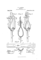
- Figure 1 is a perspective view of the tug and attached billet, the buckle being omitted and the rivet and its washer shown inline for insertion.
- Fig. 2 is a perspective view of the tug and billet with the buckle in place and the parts riveted together.
- Fig. 3 is a longitudinal section of the parts as shown in Fig. 2.
- 'Fig 4 shows the tug displayed, with the outside strap broken away to expose the billet nut.
- Fig. 5 is a longitudinal section of the lower part of the tug, showing a modified billet connection.
- l is the foundation piece, to which is fastened the strap loop 2, and on the outside of which is the longitudinal strap 3, sewed or Specification of Letters Patent.
- This free end 4 is slotted at 5 to receive the tongue of the buckle.
- the free end 4 has the rivet holes 6 and 7, and the foundation piece l has the rivet holes 8 and 9, which holes are adapted to be brought into alinement with the rivet holes in the free end il when the buckle is in place, by bending said free end over upon itself, and then all of these parts may be secured by a single fastener, such as a rivet l0 and its washer ll, as shown in Figs. 2 and 3.
- the tug is designed to be put upon the market without an attached buckle, and in the form shown in Fig. l, and when the purchaser has selected the desired buckle it is slipped into the free end and the rivet inserted and all of the parts secured, ready for use. But the tug may be put upon the marketwith the buckle in place and the parts riveted, and then if the purchaser wishes a differentkind of buckle, it is only necessary to cut out the rivet, put in the preferred buckle and rivet the parts together anew, and this may be done without marring the sewing or injuriously affecting or marring any of the parts.
- the construction enables a dealer to meet every wish or fancy of the buyer as to kind, style or finish of buckle quickly and inexpensively.
- the parts will be bent to shape by the manufacturer so as to facilitate the work of the dealer in applying the buckle.
- a nut 12 at the base of the tug is inserted between the foundation piece l and the strap 3 and the billet strap 13 has a screw-eye 14 which may be applied to and removed from this nut at pleasure as the user employs a double or single girth.
- the nut is practically concealed, and hence is inconspicuous at all times.
- Fig. 5 illustrates the fact that the tug may be supplied with the ordinary dee and billet.
- the dee l5 has attached to it the billet as in the former instance, and the dee is secured to the foundation strap by the clip 16, which is of metal bent to shape to receive the dee and conform to the curvature of the tug and is riveted or otherwise fastened to the foundation piece.
- the strap 3 is sewed down over and aboutl the clip.
- the two forms of billet-attaching devices have in common a member which is permanently secured to the tugs foundation piece and in effect concealed in it.
- a thill tug adapted for interchange of buckles, comprising a foundation piece, and a strap permanently attached to the foundation piece and having a buckle-receiving free end, the foundation piece and its attached strap having both of their ends supplied with holes and the buckle-receiving free end likewise having oppositely arranged holes, all of which holes being brought into alinement when the foundation piece and strap are bent around to complete the tug, to adapt the holes to receive a fastener for uniting these parts and the buckle.
- a thill tug having a foundation piece with rivet holes near its opposite ends, a strap loop fixed to said foundation piece, a strap xed to the foundation piece for a portion of its length and having a free end to engage a buckle bar and slotted for the passage of the tongue of the buckle and provided with rivet holes near opposite ends of the slot so that When this free end is bent around the buckle bar and the ends of the foundation piece are brought opposite one another the several rivet holes Will be brought into alineinent to receive a rivet by which all of the parts may be united, thereby permitting interchange of buckles.
- a thill tug adapted for interchange of buckles, and comprising a foundation piece having near its opposite ends rivet holes, a strap permanently fastened to said foundation piece throughout a greater portion of its length and provided with a buckle-receiving free end which is also provided with rivet holes, all of said rivet holes adapted to be brought into alineinent with each other when the foundation piece and its attached strap are bent around to complete the tug, a buckle applied to said bucklereceiving end, and a rivet passed through the several rivet holes and serving to unite all of these parts.
Landscapes
- Engineering & Computer Science (AREA)
- Mechanical Engineering (AREA)
- Slide Fasteners, Snap Fasteners, And Hook Fasteners (AREA)
Description
W. J.v CAMPBELL.
THILL TUG.
APPLICATION FILED SEPT. zz, 190s.
Patented Feb.8,1910.
ITED SATES TFT FFIQE.
lWILLIAM J. CAMPBELL, OF DAYTON, VIRGINIA, ASSIGNOR OF ONE-HALF TO ROBERT L. CAMPBELL, OF DAYTON, VIRGINIA.
THILL-TUG.
To all whom it may concern:
Be it known that I, IVILLIAM J. CAMP- BELL, a citizen of the United States, residing at Dayton, in the county of Rockingham and State of Virginia, have invented a certain new and useful Improvement in Thill-Tugs, of which the following is a full, clear, and exact description.
Buyers of thill or shaft tugs often express preferences for the kind, finish or style of buckle used thereon, and it has been the common practice of manufacturers to sup ply these tugs with buckles permanently attached, so that many styles of tugs, varying only in the kind, style or finish of buckles, had to be kept in stock in order to satisfy buyers. It is not always possible to remove the buckle from the finished tugs and replace it with one preferred by the buyer, and even when this is done, the removed buckle is usually useless stock. In order to meet this condition of the trade, I have devised a tug, complete as an article of manufacture and trade, in which the bucklesecuring strap is left unfastened but ready to receive the preferred buckle and the parts then capable of being secured by a suitable fastener, such as a rivet, and the tug thus made ready for use without delay. It is also a matter of utility and economy to make thill tugs interchangeable for single and double girths, and this I effect by concealing a nut in the tug and supplying` a screwthreaded billet eye which may be applied to and detached from the nut at pleasure and so adapt the tug for either style of girth or bellyband.
In the accompanying drawings, illustrating the invention, in the several figures of which like parts are similarly designated, Figure 1 is a perspective view of the tug and attached billet, the buckle being omitted and the rivet and its washer shown inline for insertion. Fig. 2 is a perspective view of the tug and billet with the buckle in place and the parts riveted together. Fig. 3 is a longitudinal section of the parts as shown in Fig. 2. 'Fig 4 shows the tug displayed, with the outside strap broken away to expose the billet nut. Fig. 5 is a longitudinal section of the lower part of the tug, showing a modified billet connection.
l is the foundation piece, to which is fastened the strap loop 2, and on the outside of which is the longitudinal strap 3, sewed or Specification of Letters Patent.
Application led September 22, 1908.
Patented Feb. 8, 1910. serial No. 454,221.
otherwise securely fastened to piece l from one end to the loop 2, and left free or unattached for the rest of its length. This free end 4 is slotted at 5 to receive the tongue of the buckle. The free end 4 has the rivet holes 6 and 7, and the foundation piece l has the rivet holes 8 and 9, which holes are adapted to be brought into alinement with the rivet holes in the free end il when the buckle is in place, by bending said free end over upon itself, and then all of these parts may be secured by a single fastener, such as a rivet l0 and its washer ll, as shown in Figs. 2 and 3.
The tug is designed to be put upon the market without an attached buckle, and in the form shown in Fig. l, and when the purchaser has selected the desired buckle it is slipped into the free end and the rivet inserted and all of the parts secured, ready for use. But the tug may be put upon the marketwith the buckle in place and the parts riveted, and then if the purchaser wishes a differentkind of buckle, it is only necessary to cut out the rivet, put in the preferred buckle and rivet the parts together anew, and this may be done without marring the sewing or injuriously affecting or marring any of the parts.
The construction enables a dealer to meet every wish or fancy of the buyer as to kind, style or finish of buckle quickly and inexpensively.
The parts will be bent to shape by the manufacturer so as to facilitate the work of the dealer in applying the buckle. Between the foundation piece l and the strap 3 is inserted a nut 12 at the base of the tug, and the billet strap 13 has a screw-eye 14 which may be applied to and removed from this nut at pleasure as the user employs a double or single girth. The nut is practically concealed, and hence is inconspicuous at all times.
Fig. 5 illustrates the fact that the tug may be supplied with the ordinary dee and billet. In this case the dee l5 has attached to it the billet as in the former instance, and the dee is secured to the foundation strap by the clip 16, which is of metal bent to shape to receive the dee and conform to the curvature of the tug and is riveted or otherwise fastened to the foundation piece. The strap 3 is sewed down over and aboutl the clip.
The two forms of billet-attaching devices have in common a member which is permanently secured to the tugs foundation piece and in effect concealed in it.
By my invention a very simple and useful tug is furnished, by which two urgent needs of buyers may be readily and effectively supplied.
What I claim is 1. A thill tug, adapted for interchange of buckles, comprising a foundation piece, and a strap permanently attached to the foundation piece and having a buckle-receiving free end, the foundation piece and its attached strap having both of their ends supplied with holes and the buckle-receiving free end likewise having oppositely arranged holes, all of which holes being brought into alinement when the foundation piece and strap are bent around to complete the tug, to adapt the holes to receive a fastener for uniting these parts and the buckle.
2. A thill tug, having a foundation piece with rivet holes near its opposite ends, a strap loop fixed to said foundation piece, a strap xed to the foundation piece for a portion of its length and having a free end to engage a buckle bar and slotted for the passage of the tongue of the buckle and provided with rivet holes near opposite ends of the slot so that When this free end is bent around the buckle bar and the ends of the foundation piece are brought opposite one another the several rivet holes Will be brought into alineinent to receive a rivet by which all of the parts may be united, thereby permitting interchange of buckles.
3. A thill tug, adapted for interchange of buckles, and comprising a foundation piece having near its opposite ends rivet holes, a strap permanently fastened to said foundation piece throughout a greater portion of its length and provided with a buckle-receiving free end which is also provided with rivet holes, all of said rivet holes adapted to be brought into alineinent with each other when the foundation piece and its attached strap are bent around to complete the tug, a buckle applied to said bucklereceiving end, and a rivet passed through the several rivet holes and serving to unite all of these parts.
In testimony whereof I have hereunto set my hand this 21st day of Sept. A. D. 1908.
IVILLIAM J. CAMPBELL. lVitnesses:
L. E. RUEBUSH, Jon K. RUnBUsH.
Priority Applications (1)
| Application Number | Priority Date | Filing Date | Title |
|---|---|---|---|
| US45422108A US948780A (en) | 1908-09-22 | 1908-09-22 | Thill-tug. |
Applications Claiming Priority (1)
| Application Number | Priority Date | Filing Date | Title |
|---|---|---|---|
| US45422108A US948780A (en) | 1908-09-22 | 1908-09-22 | Thill-tug. |
Publications (1)
| Publication Number | Publication Date |
|---|---|
| US948780A true US948780A (en) | 1910-02-08 |
Family
ID=3017195
Family Applications (1)
| Application Number | Title | Priority Date | Filing Date |
|---|---|---|---|
| US45422108A Expired - Lifetime US948780A (en) | 1908-09-22 | 1908-09-22 | Thill-tug. |
Country Status (1)
| Country | Link |
|---|---|
| US (1) | US948780A (en) |
-
1908
- 1908-09-22 US US45422108A patent/US948780A/en not_active Expired - Lifetime
Similar Documents
| Publication | Publication Date | Title |
|---|---|---|
| US926634A (en) | Buckle. | |
| US970184A (en) | Buckle and strap loop. | |
| US260905A (en) | Thomas a | |
| US187834A (en) | Improvement in harness-trimmings | |
| US482764A (en) | Thill-tug | |
| US335143A (en) | Horse-collar pad | |
| US206307A (en) | Improvement in shaft-tugs | |
| US306484A (en) | Hitching device | |
| US191235A (en) | Improvement in whiffletree-fastenings | |
| US689459A (en) | Strap-end retainer. | |
| US545575A (en) | Shaft-tug loop | |
| US281080A (en) | Blinder for bridles | |
| US731808A (en) | Cross-line buckle. | |
| US420244A (en) | Head-check loop | |
| US397939A (en) | Tug attachment | |
| US7265A (en) | Habjstess-hahe | |
| US451891A (en) | Albert ii | |
| US923316A (en) | Cross-line buckle. | |
| US284590A (en) | Hame-tug | |
| US394780A (en) | Strap-connection | |
| US378689A (en) | Chaeles j | |
| US383122A (en) | Rosette attachment for bridles | |
| US202201A (en) | Improvement in horse-collars | |
| US590065A (en) | Hame-tug | |
| US836920A (en) | Hame-tug. |