US9479290B2 - Method and apparatus for transmitting and receiving information in a broadcasting/communication system - Google Patents
Method and apparatus for transmitting and receiving information in a broadcasting/communication system Download PDFInfo
- Publication number
- US9479290B2 US9479290B2 US13/599,551 US201213599551A US9479290B2 US 9479290 B2 US9479290 B2 US 9479290B2 US 201213599551 A US201213599551 A US 201213599551A US 9479290 B2 US9479290 B2 US 9479290B2
- Authority
- US
- United States
- Prior art keywords
- bits
- parity
- punctured
- indicates
- parameter pair
- Prior art date
- Legal status (The legal status is an assumption and is not a legal conclusion. Google has not performed a legal analysis and makes no representation as to the accuracy of the status listed.)
- Active, expires
Links
- 238000000034 method Methods 0.000 title claims abstract description 37
- 238000004891 communication Methods 0.000 title claims abstract description 22
- 230000005540 biological transmission Effects 0.000 claims description 51
- 101100340610 Mus musculus Igdcc3 gene Proteins 0.000 claims description 35
- 238000012937 correction Methods 0.000 claims description 11
- 230000010363 phase shift Effects 0.000 claims description 5
- 230000011664 signaling Effects 0.000 description 33
- 238000004904 shortening Methods 0.000 description 29
- 230000008859 change Effects 0.000 description 8
- 238000010586 diagram Methods 0.000 description 8
- 238000012545 processing Methods 0.000 description 6
- 230000015556 catabolic process Effects 0.000 description 2
- 238000006731 degradation reaction Methods 0.000 description 2
- 238000005562 fading Methods 0.000 description 2
- 230000008569 process Effects 0.000 description 2
- 230000007423 decrease Effects 0.000 description 1
- 238000012217 deletion Methods 0.000 description 1
- 230000037430 deletion Effects 0.000 description 1
- 238000011161 development Methods 0.000 description 1
- 230000000694 effects Effects 0.000 description 1
- 230000006872 improvement Effects 0.000 description 1
- 239000011159 matrix material Substances 0.000 description 1
- 238000011160 research Methods 0.000 description 1
Images

Classifications
-
- H—ELECTRICITY
- H04—ELECTRIC COMMUNICATION TECHNIQUE
- H04L—TRANSMISSION OF DIGITAL INFORMATION, e.g. TELEGRAPHIC COMMUNICATION
- H04L1/00—Arrangements for detecting or preventing errors in the information received
- H04L1/004—Arrangements for detecting or preventing errors in the information received by using forward error control
- H04L1/0056—Systems characterized by the type of code used
- H04L1/0067—Rate matching
- H04L1/0068—Rate matching by puncturing
-
- H—ELECTRICITY
- H04—ELECTRIC COMMUNICATION TECHNIQUE
- H04L—TRANSMISSION OF DIGITAL INFORMATION, e.g. TELEGRAPHIC COMMUNICATION
- H04L1/00—Arrangements for detecting or preventing errors in the information received
- H04L1/004—Arrangements for detecting or preventing errors in the information received by using forward error control
- H04L1/0056—Systems characterized by the type of code used
- H04L1/0057—Block codes
-
- H—ELECTRICITY
- H04—ELECTRIC COMMUNICATION TECHNIQUE
- H04L—TRANSMISSION OF DIGITAL INFORMATION, e.g. TELEGRAPHIC COMMUNICATION
- H04L1/00—Arrangements for detecting or preventing errors in the information received
- H04L1/004—Arrangements for detecting or preventing errors in the information received by using forward error control
- H04L1/0072—Error control for data other than payload data, e.g. control data
-
- H—ELECTRICITY
- H04—ELECTRIC COMMUNICATION TECHNIQUE
- H04L—TRANSMISSION OF DIGITAL INFORMATION, e.g. TELEGRAPHIC COMMUNICATION
- H04L1/00—Arrangements for detecting or preventing errors in the information received
- H04L1/004—Arrangements for detecting or preventing errors in the information received by using forward error control
- H04L1/0056—Systems characterized by the type of code used
- H04L1/0064—Concatenated codes
- H04L1/0065—Serial concatenated codes
-
- H—ELECTRICITY
- H04—ELECTRIC COMMUNICATION TECHNIQUE
- H04L—TRANSMISSION OF DIGITAL INFORMATION, e.g. TELEGRAPHIC COMMUNICATION
- H04L1/00—Arrangements for detecting or preventing errors in the information received
- H04L2001/0092—Error control systems characterised by the topology of the transmission link
- H04L2001/0093—Point-to-multipoint
Definitions
- the present invention relates generally to transmission and reception of information in a broadcasting/communication system, and more particularly, to a method and apparatus for controlling a code rate according to transmission and reception of signaling information in a broadcasting/communication system.
- a broadcasting/communication system may experience poor link performance due to noise, a fading phenomenon, and Inter-Symbol Interference (ISI).
- ISI Inter-Symbol Interference
- an error-correcting code e.g., a Low-Density Parity Check (LDPC) code, for improving the reliability of broadcasting/communication by efficiently restoring distortion of information to an original state.
- LDPC Low-Density Parity Check
- an LDPC encoder receives LDPC information bits (or an LDPC information word or an LDPC uncoded block) having K ldpc bits to generate LDPC coded bits (or an LDPC code word, an LDPC codeword, or an LDPC coded block) having N ldpc bits. If the length of LDPC information bits input to the LDPC encoder, K ldpc , is shorter than the length of an input information bits (or input information word) to be encoded, K sig , then a transmission end performs encoding after a shortening process.
- the present invention is designed to address at least the problems and/or disadvantages described above and to provide at least the advantages described below.
- An aspect of the present invention is to provide a method and apparatus for transmitting and receiving information in a broadcasting/communication system.
- Another aspect of the present invention is to provide a method and apparatus for controlling a code rate in a broadcasting/communication system.
- Another aspect of the present invention is to provide a method and apparatus for selecting a shortening/puncturing rate according to a length of an information word in a broadcasting/communication system.
- Another aspect of the present invention is to provide a method and apparatus for determining a number of bits to be punctured according to a length of an input information word in a broadcasting/communication system.
- a method for transmitting information in a broadcasting/communication system includes comparing a number of bits of an information word to be transmitted with a predetermined threshold value, if the number of bits of the information word is less than the threshold value, determining a first parameter pair, if the number of bits of the information word is not less than the threshold value, determining a second parameter pair, determining a number of bits to be punctured based on one of the first parameter pair and the second parameter pair, and puncturing the determined number of bits to be punctured, with respect to parity bits of a codeword generated by encoding the information word.
- an apparatus for transmitting information in a broadcasting/communication system includes an encoder for encoding an information word to be transmitted and outputting a codeword; a controller for comparing a number of bits of the information word with a predetermined threshold value, determining a first parameter pair, if the number of bits of the information word is less than the predetermined threshold value, determining a second parameter pair, if the number of bits of the information word is not less than the predetermined threshold value, and determining a number of bits to be punctured, based on one of the first parameter pair and the second parameter pair; and a puncturer for puncturing the determined number of bits to be punctured, with respect to parity bits of the codeword.
- a method for receiving information in a broadcasting/communication system includes comparing a number of bits of an information word transmitted by a transmission end with a predetermined threshold value, determining a first parameter pair, if the number of bits of the information word is less than the predetermined threshold value, determining a second parameter pair, if the number of bits of the information word is not less than the predetermined threshold value, determining a number of bits to be punctured, based on one of the first parameter pair and the second parameter pair, generating values corresponding to bits punctured by the transmission end and padding the generated values to a modulated signal of a received signal to generate a decoder input by using the determined number of bits to be punctured, and decoding the decoder input to reconstruct information word bits.
- an apparatus for receiving information in a broadcasting/communication system includes a demodulator for demodulating a received signal; a controller for obtaining information about a number of bits of an information word transmitted from a transmission end, comparing the number of bits of the information word transmitted by the transmission end with a predetermined threshold value, determining a first parameter pair, if the number of bits of the information word is less than the predetermined threshold value, determining a second parameter pair, if the number of bits of the information word is not less than the predetermined threshold value, and determining a number of bits to be punctured, based on one of the first parameter pair and the second parameter pair; a puncturing processor for generating values corresponding to the bits punctured by the transmission end by using the determined number of bits to be punctured, and padding the generated values to an output signal of the demodulator; and a decoder for receiving and decoding output values of the puncturing processor to reconstruct information word bits.
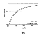
- FIG. 1 is a graph illustrating a change in a code rate according to an embodiment of the present invention
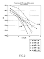
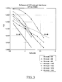
- FIGS. 2 and 3 are graphs illustrating efficiency of an LDPC code according to an embodiment of the present invention.
- FIG. 4 is a graph illustrating a change in an effective code rate according to an embodiment of the present invention.
- FIG. 5 is a graph illustrating efficiency of an LDPC code according to an embodiment of the present invention.
- FIG. 6 is a flowchart illustrating a procedure for puncturing parity bits based on an information bit length according to an embodiment of the present invention
- FIG. 7 is a diagram illustrating a frame structure for transmitting two types of parity bits according to an embodiment of the present invention.
- FIG. 8 is a diagram illustrating a structure of an LDPC code for supporting transmission of parity bits according to an embodiment of the present invention
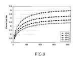
- FIG. 9 is a graph illustrating a change in an effective code rate according to an embodiment of the present invention.
- FIG. 10 is a flowchart illustrating a procedure for determining a number of two types of parity bits according to an embodiment of the present invention
- FIG. 11 a block diagram illustrating a transmission end according to an embodiment of the present invention.
- FIG. 12 is a block diagram illustrating a receiving end according to an embodiment of the present invention.
- DVD-T2 Digital Video Broadcasting the 2 nd Generation Terrestrial
- DVD-NGH Digital Video Broadcasting Next Generation Handheld
- N ldpc K ldpc +N parity
- a transmission end may perform shortening and/or puncturing (hereinafter referred to as “shortening/puncturing”). That is, if a length of LDPC information bits of the LDPC encoder is K ldpc and signaling bits having a bit length of K sig are input to the LDPC encoder, (K ldpc ⁇ K sig ) bits are shortened.
- shortening means padding (K ldpc ⁇ K sig ) ‘0’ bits to the signaling bits for LDPC encoding, and after LDPC encoding, deleting the padded ‘0’ bits, or reducing the size of a parity check matrix of the LDPC encoder, which has the same effect as shortening based on the padding and deletion.
- puncturing means excluding some of encoding bits, especially, parity bits, from a transmission.
- the transmission end of the broadcasting/communication system may use two concatenated encoders.
- an encoder that concatenates a Bose, Chaudhuri, Hocquenghem (BCH) code with an LDPC code i.e., a BCH/LDPC encoder, receives BCH information bits (BCH information or information bits) having K bch bits and outputs BCH coded bits (or BCH codeword or a BCH coded block) having N bch bits.
- N bch is equal to the number of LDPC information bits, K ldpc
- the N bch bits may also be referred to as LDPC information bits (or an LDPC uncoded block), which is information input to the LDPC encoder.
- the BCH coded bits i.e., the LDPC information bits
- a transmission end When an information word, which includes signaling bits having a variable length, is input to an encoder, a transmission end performs shortening/puncturing with respect to a codeword output from the encoder. That is, signaling bits having a bit length of K sig are input to the BCH/LDPC encoder and (K bch ⁇ K sig ) bits are shortened. As described above, shortening means that (K bch ⁇ K sig ) ‘0’ bits are padded to the input signaling bits and are BCH/LDPC encoded, and then the padded ‘0’ bits are deleted.
- shortening reduces a code rate, such that as the number of bits to be shortened (i.e., a shortening bit length) increases, encoding performance improves.
- encoding performance should not vary with the length of input information. That is, when reception power in a receiver is constant, it is preferable that performance should not differ with the length of input information word. Therefore, by adjusting the number of bits to be punctured (i.e., a puncturing bit length) according to the number of bits to be shortened, stable encoding performance is provided.
- the number of bits to be punctured is determined according to a bit length of input information word, i.e., a bit number of the input information word, such that the number of bits to be punctured depends on the bit number of the input information word.
- N punc may be calculated using one of Equations (1) to (4).
- Equation (1) is used when a BCH code is concatenated and Equation (2) is used when a BCH code is not concatenated. That is, when the BCH code is concatenated, the number of bits to be shortened is (K bch ⁇ K sig ), such that N punc may be calculated using Equation (1).
- N punc ⁇ A ⁇ ( K bch ⁇ K sig ) ⁇ B ⁇ where 0 ⁇ B (1)
- N punc ⁇ A ⁇ ( K ldpc ⁇ K sig ) ⁇ B ⁇ where 0 ⁇ B (2)
- A indicates a rate of the number of bits to be shortened to the number of bits to be punctured
- (K bch ⁇ K sig ) and (K ldpc ⁇ K sig ) indicate the number of bits to be shortened
- K bch indicates the number of BCH information bits (i.e., an information bit length) input to generate BCH coded bits including K ldpc bits through BCH encoding.
- K ldpc indicates the number of LDPC information bits input to generate the LDPC coded bits.
- K sig indicates a bit length of an information word input to the encoder before shortening
- B indicates a correction factor.
- the operation ⁇ x ⁇ indicates a floor function and means the largest integer less than or equal to x.
- N punc ⁇ A ⁇ ( K bch ⁇ K sig )+ B ⁇ where 0 ⁇ B ⁇ N parity ⁇ A ( K bch ⁇ K sig _ min ) (3)
- N punc ⁇ A ⁇ ( K ldpc ⁇ K sig )+ B ⁇ where 0 ⁇ N parity ⁇ A ( K ldpc ⁇ K sig _ min ) (4)
- A indicates a rate of the number of bits to be shortened to the number of bits to be punctured
- (K bch ⁇ K sig ) and (K ldpc ⁇ K sig ) indicate the number of bits to be shortened
- K bch indicates the number of BCH information bits (i.e., an information bit length) input to generate BCH coded bits composed of K ldpc bits through BCH encoding.
- K ldpc indicates the number of LDPC information bits input to generate the LDPC coded bits.
- K sig indicates a bit length of an information word input to the encoder before shortening
- B indicates a correction factor.
- K sig _ min indicates a bit length of the shortest information word among information words that can be input to the encoder.
- N punc is smaller than the number of parity bits, N parity , only when a condition of B ⁇ N parity ⁇ A(K ldpc ⁇ K sig _ min ) is satisfied.
- N punc may change according to the parameters A and B. Accordingly, a code rate may change according to A and B.
- a code rate of an LDPC code, R may be calculated using Equation (5).
- Equation (6) For K sig input information word bits, an effective code rate R eff after shortening and puncturing is calculated using Equation (6).
- N bch _ parity indicates the number of parity bits of a BCH code, which is 0 when a BCH code is not used.
- FER Frame Error Rate
- a code rate is lower than that in FIG. 2 , such that overall performance improvement is achieved.
- K sig the number of input information bits
- N punc is determined using Equations (7) and (8).
- Equations (7) and (8) different values of A and B, i.e., A 1 and B 1 or A 2 and B 2 are used according to an input information bit length.
- Equation (7) can be modified to the following Equation (7a).
- N punc ⁇ A ⁇ ( K bch ⁇ K sig ) ⁇ + B 1 (7a)
- Equation (7) can be modified into Equation (7b).
- Equation (8) can be modified in similar to the Equations (7a) and (7b).
- Equations (7) and (8) a case of an input information bit length being less than a predetermined threshold value K th and a case of the input information bit length being greater than the threshold value K th are divided.
- a plurality of threshold values may be used to divide a case of the input information bit length, such that two or more pairs of A and B may be used.
- K th may be experimentally determined not to cause an encoding performance difference with N punc .
- a value corresponding to a case where performance is relatively good or a case where performance is relatively bad is determined as K th .
- the number of bits to be punctured is preferably adjusted according to the number of bits to be shortened, and the number of bits to be shortened is determined according to a bit length of an input information word.
- a 1 and A 2 indicating ratios of the number of bits to be shortened to the number of bits to be punctured may be constant values determined according to a bit length of an input information word. Therefore, B 1 and B 2 may be determined as constant values.
- the transmission end punctures parity bits among coded bits generated by encoding input information bits with N punc .
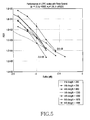
- K sig is more than 1350, which is equal to K th
- FIG. 5 is a graph illustrating an FER according to an embodiment of the present invention. Specifically, FIG. 5 illustrates FER performance with respect to various information bit lengths of 280, 396, 880, 1350, 1550, 1670, and 1900.
- a code rate is lower than illustrated in FIG. 2 , such that performance is better.
- a code rate is higher than illustrated in FIG. 3 , such that performance degradation occurs. Therefore, an overall performance difference is 0.3 dB and an encoding performance difference is reduced when compared to FIGS. 2 and 3 .
- N punc the number of bits to be punctured, N punc .
- N punc the number of bits to be punctured, N punc .
- a value obtained using the foregoing equations is assumed to be a temporary value of N punc , i.e., a temporary number of bits to be punctured, N punc _ temp , and through several processes, N punc is obtained more precisely.
- the transmission end when performing puncturing by using N punc , may more precisely adjust N punc according to additional parameters, e.g., the number of BCH parity bits, a modulation order, etc.
- additional parameters e.g., the number of BCH parity bits, a modulation order, etc.
- Equation (9) The temporary number of bits to be punctured, N punc _ temp is calculated using Equation (9), which is substantially the same as the above-described Equation (7) and the description related thereto.
- N punc ⁇ _ ⁇ temp ⁇ If ⁇ ⁇ K sig ⁇ 1350 , ⁇ 1.3 ⁇ ( K bch - K sig ) + 3357 ⁇ Otherwise , ⁇ 1.35 ⁇ ( K bch - K sig ) + 3320 ⁇ , ( 9 )
- N post _ temp The temporary number of bits to be encoded, N post _ temp , is calculated using N punc _ temp as shown in Equation (10).
- N post _ temp K sig +N bch _ parity +N ldpc _ parity _ ext _ 4K ⁇ N punc _ temp (10)
- K sig indicates the number of input information bits as described above, and for example, it may indicate the number of signaling information bits.
- N bch _ parity indicates the number of BCH parity bits, and N ldpc _ parity _ ext _ 4K indicates a constant value determined according to a type of an LDPC code.
- N post ⁇ N post ⁇ _ ⁇ temp 2 ⁇ ⁇ MOD ⁇ ⁇ 2 ⁇ ⁇ MOD ( 11 ⁇ a )
- ⁇ MOD indicates a modulation order, which is 1, 2, 4, and 6 for Binary Phase Shift Keying (BPSK), Quadrature PSK (QPSK), 16-ary Quadrature Amplitude Modulation (16-QAM), and 64-ary QAM (64-QAM), respectively.
- BPSK Binary Phase Shift Keying
- QPSK Quadrature PSK
- 16-ary Quadrature Amplitude Modulation (16-QAM)
- 64-QAM 64-ary QAM
- N post Determining the number of encoded bits of each information word block, N post , as shown in Equation (11a), causes N post to be a multiple of the number of columns of a block interleaver.
- the block interleaver although not being shown and additionally described, is used when bits of each LDPC block is bit-interleaved later.
- Equation (11a) can be converted into Equation (11b).
- N post ⁇ N post ⁇ _ ⁇ temp ⁇ MOD ⁇ ⁇ ⁇ MOD ( 11 ⁇ b )
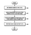
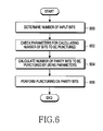
- FIG. 6 is a flowchart illustrating a procedure for puncturing parity bits based on an input information bit length according to an embodiment of the present invention.
- the transmission end checks parameters for calculating the number of bits to be punctured, i.e., a puncturing bit length. That is, the transmission end determines whether to select (A 1 , B 1 ) or (A 2 , B 2 ) according to the input information bit length using Equations (7) and (8). Although not shown, one of two or more predetermined parameter pairs may be selected according to the input information bit length.
- step 604 the number of parity bits to be punctured (i.e., a puncturing parity bit length) is calculated based on the determined parameters, e.g., using Equations 7 and 8 or Equations (9) to (12).
- step 606 parity bits of a codeword are punctured based on the calculated puncturing parity bit length.
- the parity bits generated with respect to the signaling bits, which are the input information bits, may be transmitted in a distributed manner through the same frame as a frame in which the signaling bits are transmitted and a preceding frame.
- the parity bits transmitted through the same frame as that which carries the signaling bits will be referred to herein as a first parity
- the parity bits transmitted through the preceding frame will be referred to herein as a second parity or an additional parity.
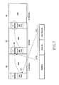
- FIG. 7 is a diagram illustrates a frame structure for transmitting two types of parity bits according to an embodiment of the present invention.
- Layer-1 signaling bits are transmitted through an i th frame 702 ; a first parity 710 generated for signaling bits is transmitted through the i th frame 702 , together with the signaling bits; and an additional parity 712 is transmitted through an (i ⁇ 1) th frame 700 .
- a reception end performs decoding based on the signaling bits and the first parity 710 received through the i th frame 702 . If decoding fails, the reception end also performs decoding using the additional parity 712 received through the (i ⁇ 1) th frame 700 .
- the reception end determines that decoding with respect to the signaling bits fails, stores an additional parity included in the i th frame 702 , and then receives an (i+1) th frame.
- the reception end stores the additional parity 712 received through the (i ⁇ 1) th frame 700 at all times, and performs decoding based on the signaling bits and the first parity 710 received through the i th frame 702 and the stored additional parity 712 .
- the number of additional parity bits may be expressed using Equation (13).
- N tx _ parity indicates the number of parity bits transmitted through the same frame as that for an information word (i.e., the first parity bits), and may also mean the number of parity bits to be actually transmitted. In this case, N tx _ parity may be calculated as N parity ⁇ N punc .
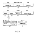
- FIG. 8 is a diagram illustrating an LDPC code for supporting parity transmission according to an embodiment of the present invention.
- an LDPC codeword includes K ldpc LDPC information bits 800 , N parity parity bits 802 , and M IR Incremental Redundancy (IR) parity bits 804 .
- the N parity parity bits 802 and the M IR IR parity bits 804 are collectively referred to herein as parity bits.
- the structure of the LDPC code illustrated in FIG. 8 is designed considering the parity bits 802 . Therefore, in puncturing, the IR parity bits 804 are punctured.
- the LDPC code of FIG. 8 may be expressed as parity bits, without discrimination between the parity bits 802 and the IR parity bits 804 .
- the LDPC information bits 800 may include the signaling bits 806 , parity bits 807 for a BCH code, and ‘0’ padding bits 808 for shortening.
- the parity bits 802 and the IR parity bits 804 include non-punctured parity bits 810 , and punctured parity bits 812 .
- a detailed position (i.e., an index) of each bit is not relevant to the subject matter of the present invention, i.e., which bits between the parity bits 802 and the IR parity bits 804 are to be punctured and which bits therebetween are not to be punctured. Accordingly, a specific puncturing pattern, will not be described herein.
- the parity bits 807 of the BCH code exist when a concatenated code of the BCH code and the LDPC code is used, and the BCH parity bits 807 will be omitted when only the LDPC code is used.
- the signaling bits 806 , the BCH parity bits 807 , and the non-punctured parity bits 810 form a first part 814 , which is later transmitted through the i th frame 702 , as illustrated in FIG. 7 .
- Some of the punctured parity bits 812 form an additional parity 816 , which is later transmitted through the (i ⁇ 1) th frame 700 , as illustrated in FIG. 7 . That is, some of the punctured parity bits 812 are the same as the additional parities 807 and 712 .
- the additional parity 708 may be determined a number of ways.
- the punctured parity bits 812 may be preferentially selected as an additional parity.
- N punc may be calculated, based on Equation 7, using Equation (14) below.
- N punc parity bits obtained based on N punc _ temp of Equation (9), using Equations (10) to (12), may be punctured.
- Detailed values of parameters used to calculate N punc may be determined according to a modulation scheme used for transmission and the number of Orthogonal Frequency Division Multiplexing (OFDM) symbols.
- OFDM Orthogonal Frequency Division Multiplexing
- K sig +N bch _ parity +N parity +M IR ⁇ N punc the number of bits to be transmitted
- K sig indicates the number of input signaling information bits
- N bch _ parity indicates the number of parity bits of a BCH code
- n indicates an order of a modulation scheme.
- the number of bits of the additional parity 712 of FIG. 7 or the additional parity 816 of FIG. 8 may be calculated using Equation (15).
- ⁇ is determined to be a maximum value among values in which a sum of the number of first parity bits, N tx _ parity , and the number of additional parity bits, N add _ parity , which are transmitted when I l is the maximum value I L-1 and K sig is the maximum length among input information bits, K sig _ max , that is, (N tx _ parity +N add _ parity ) is maximal and the sum is less than (N parity +M IR ).
- Equation (16) assumes that the BPSK modulation scheme is used. That is, ⁇ is determined such that the number of first parity bits and the number of additional parity bits transmitted when using the BPSK modulation scheme is used is less than N parity +M IR . Therefore, when another modulation scheme, e.g., QPSK, 16-QAM, or 64-QAM is used, correction with respect to N add _ parity is required such that the number of first parity bits and the number of additional parity bits is less than N parity +M IR . Therefore, the number of temporary additional parity bits may be obtained using Equation (17).
- N add _ parity _ temp min(( N parity ⁇ N punc ), ⁇ 0.35 ⁇ K ⁇ ( N parity ⁇ N punc ) ⁇ ) (17)
- K indicates an L1 additional parity ratio, and is another expression of I i from Equations (13) and (15).
- K may be transmitted from the transmitter to the receiver through signaling ‘L1_AP_RATIO’.
- Equation (18a) N add _ parity _ temp of Equation (17) and a modulation order.
- N add ⁇ _ ⁇ parity ⁇ N add ⁇ _ ⁇ parity ⁇ _temp 2 ⁇ ⁇ MOD ⁇ ⁇ 2 ⁇ ⁇ MOD ( 18 ⁇ a )
- ⁇ MOD indicates a modulation order, which is 1, 2, 4, and 6 for BPSK, QPSK, 16-QAM, and 64-QAM, respectively.
- N add _ parity is adjusted in Equation (18a) to cause N add _ parity to be a multiple of the number of columns of the block interleaver.
- the block interleaver is used when each bit of the additional parity is bit-interleaved.
- Equation (18a) can be converted into Equation (18b).
- N add _ parity is determined according to the number of OFDM symbols used for transmission.
- L1_AP_SIZE indicates a product of the number of coded blocks and N add _ parity .
- L1_AP_SIZE may indicate 2 ⁇ N add _ parity .
- the receiver may know the number of additional parity bits from that signaling parameter.
- FIG. 9 is a graph illustrating a code rate when a number of additional parity bits is calculated using Equation (15), according to an embodiment of the present invention.
- the code rate is calculated using Equation (19).
- N tx _ parity indicates the number of parity bits of the first part 814 of FIG. 8
- N ldpc +M IR ⁇ N punc 6480 ⁇ N punc
- N add _ parity indicates the number of additional parity bits of the part 816 of FIG. 8 .
- the IR parity bits 804 of the LDPC code in FIG. 8 may be selectively used. That is, the parity bits 802 are preferentially generated for input information word bits, and the IR parity bits 804 may be generated only when the IR parity is necessary, thereby improving encoding/decoding efficiency.
- the parity bits 802 are preferentially generated for input information bits, and for the parity bits 802 , N punc may be calculated based on Equation (7), as shown in Equation (20).
- Equation (20) if N punc is a positive integer, only the parity bits 802 are generated and only N punc parity bits of the parity bits 802 are punctured. However, if N punc is a negative value, both the parity bits 802 and the IR parity bits 804 are generated, and then only (M IR +N punc ) bits of the IR parity bits 804 are punctured.
- N punc obtained using Equations (10) to (12), based on Equation (20)
- parity bits are punctured.
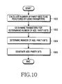
- FIG. 10 is a flowchart illustrating a procedure for determining a number of two types of parity bits according to an embodiment of the present invention.
- step 1000 the number of parity bits to be punctured is calculated using Equations (7) and (8) or Equations (9) to (12).
- step 1002 parameters, ⁇ , I l , and N tx _ parity which are used in Equations (13), (15), and (17), are determined.
- step 1002 already-determined ⁇ or I l may be used, and I l is expressed as K in Equations (17) and (18). As described above, K may be indicated by separate signaling ‘L1_AP_RATIO’.
- step 1004 the number of additional parity bits, N add _ parity is determined based on Equation (13) or Equations (17) and (18), using the parameters determined in step 1002 .
- step 1006 the additional parity bits are configured according to the calculated number of additional parity bits.
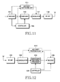
- FIG. 11 is a block diagram of a transmission end according to an embodiment of the present invention.
- the transmission end includes an encoder 1101 , a puncturer 1103 , a controller 1105 , a modulator 1107 , a Radio Frequency (RF) unit 1109 , and selectively, an additional parity configuring unit 1111 .
- RF Radio Frequency
- the encoder 1101 outputs encoded bits generated by encoding information word bits for transmission. For example, when a BCH/LDPC code is used, the encoder 1101 encodes BCH information bits having K bch bits to generate a BCH codeword having K ldpc bits. Thereafter, the encoder 1101 performs LDPC-encoding on the BCH codeword, thus generating and outputting an LDPC codeword having N ldpc bits.
- the encoder 1101 generates and outputs an LDPC codeword having (N ldpc +M IR ) bits.
- the BCH information bits having K bch bits may be configured by padding (K bch ⁇ K sig ) ‘0’ bits into K sig input information bits.
- the padded (K bch ⁇ K sig ) ‘0’ bits are not to be transmitted.
- the puncturer 1103 punctures a codeword provided from the encoder 1101 according to a puncturing pattern and a puncturing bit length (K bch ⁇ K sig ), which are provided from the controller 1105 .
- the controller 1105 calculates the puncturing bit length according to the number of information bits to control the puncturer 1103 . For example, the controller 1105 determines A and B according to the number of input information bits (or the number of signaling bits) for transmission at the transmission end, and provides the determined A and B to the puncturer 1103 .
- the controller 1105 obtains the number of bits to be punctured from the determined parameters A and B, and provides the obtained number of bits to be punctured to the puncturer 1103 .
- the modulator 1107 modulates, according to a corresponding modulation scheme, and outputs a signal provided from the puncturer 1103 .
- the RF unit 1109 converts the modulated signal provided from the modulator 1107 into a high-frequency signal and transmits the high-frequency signal through an antenna.
- the controller 1105 determines the number of additional parity bits, as illustrated in FIG. 10 , and provides the determined number of additional parity bits to the additional parity configuring unit 1111 .
- the additional parity configuring unit 1111 configures the additional parity bits and provides them to the modulator 1107 . It should be noted that additional parities generated in the current frame are transmitted through a previous frame.
- FIG. 12 is a block diagram of a reception end according to an embodiment of the present invention.
- the reception end includes an RF unit 1200 , a demodulator 1202 , a shortening/puncturing processor 1204 , a decoder 1206 , a controller 1208 , and selectively, an additional parity processing unit 1210 .
- the RF unit 1200 receives a signal transmitted from the RF unit 1109 of the transmission end and provides the signal to the demodulator 1202 .
- the demodulator 1202 demodulates the signal provided from the RF unit 1200 by utilizing a demodulation scheme corresponding to a modulation scheme used in the modulator 1107 of the transmission end. For example, the demodulator 1202 obtains a Log Likely Ratio (LLR), by taking a log of a ratio of a probability of each bit being 1 to a probability of each bit being 0 for each of shortened/punctured encoded bits and additional parity bits transmitted from the modulator 1107 , and provides the obtained LLR to the shortening/puncturing processor 1204 and the additional parity processing unit 1210 .
- the additional parity processor 1201 is optional, in that it is not used when additional parity is not received.
- the shortening/puncturing processor 1204 receives an output signal of the demodulator 1202 , generates values corresponding to shortening and puncturing with respect to the bits shortened and punctured by the transmission end, and pads the values to the output signal of the demodulator 1202 .
- an LLR value is the (+) or ( ⁇ ) maximum value among a decoder input value
- an LLR value is ‘0’.
- the shortening/puncturing processor 1204 receives information about the number of shortened and punctured bits and index from the controller 1208 . That is, the controller 1208 calculates a puncturing bit length according to the number of information bits of the encoder 1101 of the transmission end and controls the shortening/puncturing processor 1204 .
- the controller 1208 determines A and B according to the number of bits of signaling information for transmission at the transmission end, as illustrated in FIG. 6 , and provides the determined A and B to the shortening/puncturing processor 1204 .
- the controller 1208 obtains the number of bits to be punctured from the determined parameters A and B and provides the obtained number of bits to be punctured to the shortening/puncturing processor 1204 .
- Information about the number of input information bits input to the encoder of the transmission end may be transmitted to the controller 1208 of the receiver through, for example, additional signaling.
- the decoder 1206 receives and decodes output values of the shortening/puncturing processor 1204 to reconstruct information word bits. For example, when a BCH/LDPC code is used, the decoder 1206 receives N ldpc or (N ldpc +M IR ) LLR values and performs LDPC-decoding thereon to reconstruct K ldpc bits, and then reconstruct K bch information word bits through BCH decoding.
- the controller 1208 determines the number of additional parity bits, as illustrated in FIG. 10 , and provides the determined number of additional parity bits to the additional parity processing unit 1210 .
- the additional parity processing unit 1210 receives LLR values for the additional parity bits generated by the transmission end from the demodulator 1202 and provides the LLR values to the decoder 1206 .
- the decoder 1206 performs decoding by using both the values provided from the shortening/puncturing processor 1204 and the values provided from the additional parity processing unit 1210 . It should be noted that additional parities received in the current frame are used in decoding of the next frame according to processing at the transmitter. That is, in decoding of a code received in the current frame, additional parity bits received in the previous frame are used.
Applications Claiming Priority (4)
| Application Number | Priority Date | Filing Date | Title |
|---|---|---|---|
| KR10-2011-0087464 | 2011-08-30 | ||
| KR20110087464 | 2011-08-30 | ||
| KR1020120005565A KR101922555B1 (ko) | 2011-08-30 | 2012-01-18 | 방송/통신시스템에서 정보 송수신 방법 및 장치 |
| KR10-2012-0005565 | 2012-01-18 |
Publications (2)
| Publication Number | Publication Date |
|---|---|
| US20130055051A1 US20130055051A1 (en) | 2013-02-28 |
| US9479290B2 true US9479290B2 (en) | 2016-10-25 |
Family
ID=46888904
Family Applications (1)
| Application Number | Title | Priority Date | Filing Date |
|---|---|---|---|
| US13/599,551 Active 2034-03-21 US9479290B2 (en) | 2011-08-30 | 2012-08-30 | Method and apparatus for transmitting and receiving information in a broadcasting/communication system |
Country Status (3)
| Country | Link |
|---|---|
| US (1) | US9479290B2 (fr) |
| EP (1) | EP2566086B1 (fr) |
| WO (1) | WO2013032156A1 (fr) |
Families Citing this family (24)
| Publication number | Priority date | Publication date | Assignee | Title |
|---|---|---|---|---|
| KR102221303B1 (ko) * | 2013-07-05 | 2021-03-02 | 엘지전자 주식회사 | 방송신호 전송장치, 방송신호 수신장치, 방송신호 전송방법, 방송신호 수신방법 |
| KR102212425B1 (ko) | 2013-09-11 | 2021-02-05 | 삼성전자주식회사 | 송신 장치, 수신 장치 및 그들의 신호 처리 방법 |
| WO2015037921A1 (fr) | 2013-09-11 | 2015-03-19 | Samsung Electronics Co., Ltd. | Émetteur, récepteur et procédé de traitement de signal de ceux-ci |
| US9774352B2 (en) | 2013-09-17 | 2017-09-26 | Samsung Electronics Co., Ltd. | Transmitting apparatus, and puncturing method thereof |
| US9258159B2 (en) | 2013-09-18 | 2016-02-09 | Samsung Electronics Co., Ltd. | Transmitter and zero bits padding method thereof |
| WO2015041479A1 (fr) | 2013-09-18 | 2015-03-26 | Samsung Electronics Co., Ltd. | Emetteur et son procédé de perforation |
| KR101800423B1 (ko) * | 2015-02-13 | 2017-11-23 | 삼성전자주식회사 | 송신 장치 및 그의 부가 패리티 생성 방법 |
| WO2016129975A2 (fr) * | 2015-02-13 | 2016-08-18 | Samsung Electronics Co., Ltd. | Émetteur, et procédé de génération de bits de parité supplémentaires correspondant |
| KR101776267B1 (ko) * | 2015-02-24 | 2017-09-07 | 삼성전자주식회사 | 송신 장치 및 그의 리피티션 방법 |
| US10027350B2 (en) * | 2015-02-24 | 2018-07-17 | Samsung Electronics Co., Ltd. | Transmitter and repetition method thereof |
| KR102426380B1 (ko) | 2015-02-25 | 2022-07-29 | 삼성전자주식회사 | 송신 장치 및 그의 부가 패리티 생성 방법 |
| CN111865497B (zh) * | 2015-02-25 | 2023-04-14 | 三星电子株式会社 | 发送器及其产生附加奇偶校验的方法 |
| CN112165335B (zh) | 2015-02-25 | 2023-09-01 | 三星电子株式会社 | 发送设备和接收设备 |
| KR101776273B1 (ko) | 2015-02-25 | 2017-09-07 | 삼성전자주식회사 | 송신 장치 및 그의 부가 패리티 생성 방법 |
| CA2977627C (fr) | 2015-02-27 | 2020-01-07 | Sung-Ik Park | Dispositif de perforation de parite pour le codage d'informations de signalisation de longueur fixe et procede de perforation de parite faisant appel a celui-ci |
| WO2016137254A1 (fr) | 2015-02-27 | 2016-09-01 | 한국전자통신연구원 | Appareil d'entrelacement de parité pour codage d'informations de signalisation de longueur variable, et procédé d'entrelacement de parité utilisant celui-ci |
| KR102453476B1 (ko) | 2015-02-27 | 2022-10-14 | 한국전자통신연구원 | 고정 길이 시그널링 정보 부호화를 위한 패리티 인터리빙 장치 및 이를 이용한 패리티 인터리빙 방법 |
| KR102453472B1 (ko) | 2015-02-27 | 2022-10-14 | 한국전자통신연구원 | 가변 길이 시그널링 정보 부호화를 위한 패리티 펑처링 장치 및 이를 이용한 패리티 펑처링 방법 |
| WO2016137204A1 (fr) | 2015-02-27 | 2016-09-01 | 한국전자통신연구원 | Appareil d'entrelacement de parité pour codage d'informations de signalisation de longueur fixe, et procédé d'entrelacement de parité utilisant celui-ci |
| KR102453474B1 (ko) | 2015-02-27 | 2022-10-14 | 한국전자통신연구원 | 가변 길이 시그널링 정보 부호화를 위한 패리티 인터리빙 장치 및 이를 이용한 패리티 인터리빙 방법 |
| KR101800414B1 (ko) * | 2015-03-02 | 2017-11-23 | 삼성전자주식회사 | 송신 장치 및 그의 부가 패리티 생성 방법 |
| CN112291040B (zh) * | 2015-03-02 | 2024-01-26 | 三星电子株式会社 | 发送方法和接收方法 |
| WO2016140514A1 (fr) | 2015-03-02 | 2016-09-09 | Samsung Electronics Co., Ltd. | Émetteur et son procédé de segmentation |
| CA3207618A1 (fr) | 2015-03-02 | 2016-09-09 | Samsung Electronics Co., Ltd. | Emetteur et procede de generation de parite supplementaire de celui-ci |
Citations (21)
| Publication number | Priority date | Publication date | Assignee | Title |
|---|---|---|---|---|
| US20030126548A1 (en) | 2001-12-03 | 2003-07-03 | Mitsubshi Denki Kabushiki Kaisha | Method for obtaining from a block turbo-code an error correcting code of desired parameters |
| US20040153959A1 (en) | 2002-10-26 | 2004-08-05 | Samsung Electronics Co., Ltd. | LDPC decoding apparatus and method |
| US20050144543A1 (en) | 2003-12-26 | 2005-06-30 | Eun-A Choi | Pre-processing apparatus using nonuniform quantization of channel reliability value and LDPC decoding system using the same |
| US20050154958A1 (en) * | 2004-01-12 | 2005-07-14 | Bo Xia | Method and apparatus for varying lengths of low density party check codewords |
| US20060123277A1 (en) * | 2004-11-23 | 2006-06-08 | Texas Instruments Incorporated | Simplified decoding using structured and punctured LDPC codes |
| US20060190801A1 (en) | 2005-02-22 | 2006-08-24 | Samsung Electronics Co., Ltd. | Apparatus and method for generating low density parity check code using zigzag code in a communication system |
| US20070101229A1 (en) | 2005-10-27 | 2007-05-03 | Samsung Electronics Co., Ltd. | LDPC concatenation rules for 802.11n systems |
| US20070143656A1 (en) | 2005-12-20 | 2007-06-21 | Samsung Electronics Co., Ltd. | LDPC concatenation rules for IEEE 802.11n system with packets length specified in octets |
| US20090158113A1 (en) | 2007-12-13 | 2009-06-18 | Electronics And Telecommunications Research Institute | Apparatus and method for encoding ldpc code using message passing algorithm |
| US20090158129A1 (en) | 2007-12-06 | 2009-06-18 | Seho Myung | Method and apparatus for encoding and decoding channel in a communication system using low-density parity-check codes |
| US20090204869A1 (en) | 2008-02-11 | 2009-08-13 | Samsung Electronics Co., Ltd. | Method and apparatus for channel encoding and decoding in a communication system using low-density parity-check codes |
| WO2009110739A2 (fr) | 2008-03-03 | 2009-09-11 | Samsung Electronics Co., Ltd. | Procédé de codage d'informations de commande dans un système de communication sans fil et procédé et appareil de transmission et de réception d'informations de commande |
| US20090259915A1 (en) | 2004-10-12 | 2009-10-15 | Michael Livshitz | Structured low-density parity-check (ldpc) code |
| CN101567697A (zh) | 2009-05-25 | 2009-10-28 | 普天信息技术研究院有限公司 | 一种速率兼容的低密度奇偶校验码编码方法和编码器 |
| CN101630989A (zh) | 2008-07-14 | 2010-01-20 | 上海华为技术有限公司 | 一种数据发送方法、装置及通信系统 |
| CN101753264A (zh) | 2008-12-18 | 2010-06-23 | 华为技术有限公司 | 用于评价打孔图案性能的门限值的获取方法和装置 |
| US20100251062A1 (en) * | 2007-11-09 | 2010-09-30 | Panasonic Corporation | Encoding method and transmission device |
| CN101965687A (zh) | 2008-03-03 | 2011-02-02 | 三星电子株式会社 | 用于在使用低密度奇偶校验码的通信系统中的信道编码和解码的设备和方法 |
| CN102017558A (zh) | 2008-03-03 | 2011-04-13 | 三星电子株式会社 | 无线通信系统中编码控制信息的方法及用于发送和接收控制信息的方法和装置 |
| US20110119568A1 (en) * | 2009-11-18 | 2011-05-19 | Samsung Electronics Co., Ltd. | Method and apparatus for transmitting and receiving data in a communication system |
| US20130042165A1 (en) | 2008-03-03 | 2013-02-14 | Samsung Electronics Co., Ltd. | Apparatus and method for channel encoding and decoding in communication system using low-density parity-check codes |
-
2012
- 2012-08-16 WO PCT/KR2012/006516 patent/WO2013032156A1/fr active Application Filing
- 2012-08-27 EP EP12181864.5A patent/EP2566086B1/fr active Active
- 2012-08-30 US US13/599,551 patent/US9479290B2/en active Active
Patent Citations (26)
| Publication number | Priority date | Publication date | Assignee | Title |
|---|---|---|---|---|
| JP2003218707A (ja) | 2001-12-03 | 2003-07-31 | Mitsubishi Electric Inf Technol Center Europ Bv | 誤り訂正符号を得るための方法、誤り訂正符号を復号化するための方法、情報要素のブロックを符号化するための符号器、および、軟値の第1のブロックを復号化する復号器 |
| US20030126548A1 (en) | 2001-12-03 | 2003-07-03 | Mitsubshi Denki Kabushiki Kaisha | Method for obtaining from a block turbo-code an error correcting code of desired parameters |
| US20040153959A1 (en) | 2002-10-26 | 2004-08-05 | Samsung Electronics Co., Ltd. | LDPC decoding apparatus and method |
| US20050144543A1 (en) | 2003-12-26 | 2005-06-30 | Eun-A Choi | Pre-processing apparatus using nonuniform quantization of channel reliability value and LDPC decoding system using the same |
| US20050154958A1 (en) * | 2004-01-12 | 2005-07-14 | Bo Xia | Method and apparatus for varying lengths of low density party check codewords |
| US20090259915A1 (en) | 2004-10-12 | 2009-10-15 | Michael Livshitz | Structured low-density parity-check (ldpc) code |
| US20060123277A1 (en) * | 2004-11-23 | 2006-06-08 | Texas Instruments Incorporated | Simplified decoding using structured and punctured LDPC codes |
| US20060190801A1 (en) | 2005-02-22 | 2006-08-24 | Samsung Electronics Co., Ltd. | Apparatus and method for generating low density parity check code using zigzag code in a communication system |
| US20070101229A1 (en) | 2005-10-27 | 2007-05-03 | Samsung Electronics Co., Ltd. | LDPC concatenation rules for 802.11n systems |
| US20070143656A1 (en) | 2005-12-20 | 2007-06-21 | Samsung Electronics Co., Ltd. | LDPC concatenation rules for IEEE 802.11n system with packets length specified in octets |
| US20100251062A1 (en) * | 2007-11-09 | 2010-09-30 | Panasonic Corporation | Encoding method and transmission device |
| US20090158129A1 (en) | 2007-12-06 | 2009-06-18 | Seho Myung | Method and apparatus for encoding and decoding channel in a communication system using low-density parity-check codes |
| CN101889398A (zh) | 2007-12-06 | 2010-11-17 | 三星电子株式会社 | 在使用低密度奇偶校验码的通信系统中编码和解码信道的方法和装置 |
| US20090158113A1 (en) | 2007-12-13 | 2009-06-18 | Electronics And Telecommunications Research Institute | Apparatus and method for encoding ldpc code using message passing algorithm |
| CN101946413A (zh) | 2008-02-11 | 2011-01-12 | 三星电子株式会社 | 使用低密度奇偶校验码的通信系统中的信道编码和解码的方法和装置 |
| US20090204869A1 (en) | 2008-02-11 | 2009-08-13 | Samsung Electronics Co., Ltd. | Method and apparatus for channel encoding and decoding in a communication system using low-density parity-check codes |
| US20090259913A1 (en) * | 2008-03-03 | 2009-10-15 | Samsung Electronics Co., Ltd. | Method for encoding control information in a wireless communication system using low density parity check code, and method and apparatus for transmitting and receiving the control information |
| WO2009110739A2 (fr) | 2008-03-03 | 2009-09-11 | Samsung Electronics Co., Ltd. | Procédé de codage d'informations de commande dans un système de communication sans fil et procédé et appareil de transmission et de réception d'informations de commande |
| CN101965687A (zh) | 2008-03-03 | 2011-02-02 | 三星电子株式会社 | 用于在使用低密度奇偶校验码的通信系统中的信道编码和解码的设备和方法 |
| CN102017558A (zh) | 2008-03-03 | 2011-04-13 | 三星电子株式会社 | 无线通信系统中编码控制信息的方法及用于发送和接收控制信息的方法和装置 |
| JP2011514775A (ja) | 2008-03-03 | 2011-05-06 | サムスン エレクトロニクス カンパニー リミテッド | 低密度パリティ検査符号を使用する通信システムにおけるチャネル符号化及び復号化装置並びにその方法 |
| US20130042165A1 (en) | 2008-03-03 | 2013-02-14 | Samsung Electronics Co., Ltd. | Apparatus and method for channel encoding and decoding in communication system using low-density parity-check codes |
| CN101630989A (zh) | 2008-07-14 | 2010-01-20 | 上海华为技术有限公司 | 一种数据发送方法、装置及通信系统 |
| CN101753264A (zh) | 2008-12-18 | 2010-06-23 | 华为技术有限公司 | 用于评价打孔图案性能的门限值的获取方法和装置 |
| CN101567697A (zh) | 2009-05-25 | 2009-10-28 | 普天信息技术研究院有限公司 | 一种速率兼容的低密度奇偶校验码编码方法和编码器 |
| US20110119568A1 (en) * | 2009-11-18 | 2011-05-19 | Samsung Electronics Co., Ltd. | Method and apparatus for transmitting and receiving data in a communication system |
Non-Patent Citations (6)
| Title |
|---|
| Author(s): Hunter, T.E. and Nosratinia, A. ; Performance Analysis of Coded Cooperation Diversity; Date of Conference: May 11-15, 2003; Multimedia Commun. Lab., Texas Univ., Richardson, TX, USA; vol. 4 ; pp. 2688-2692 vol. 4 Product Type: Conference Publications. * |
| Chinese Office Action dated Mar. 28, 2016 issued in counterpart application No. 201280041485.8, 12 pages. |
| Digital Video Broadcasting (DVB); Next Generation Broadcasting System to Handheld, Physical Layer Specification (DVB-NGH), DVB Documnet A160, Nov. 1, 2012, 18 pages. |
| Digital Video Broadcasting, "Frame Structure Channel Coding and Modulation for a Second Generation Digital Terrestrial Television Broadcasting System (DVB-T2)," XP-002523675, DVB Document A122r1, Jan. 2008. |
| Douglas N. Rowitch and Laurence B. Milstein; On the Performance of Hybrid FEC/ARQ Systems Using Rate Compatible PuncturedTurbo (RCPT) Codes; IEEE Transactions on Communications, vol. 48, No. 6, Jun. 2000; p. 948-958. * |
| Japanese Office Action dated Feb. 8, 2016 issued in counterpart application No. 2014-528262, 8 pages. |
Also Published As
| Publication number | Publication date |
|---|---|
| EP2566086A2 (fr) | 2013-03-06 |
| EP2566086B1 (fr) | 2017-11-08 |
| WO2013032156A1 (fr) | 2013-03-07 |
| EP2566086A3 (fr) | 2014-08-27 |
| US20130055051A1 (en) | 2013-02-28 |
Similar Documents
| Publication | Publication Date | Title |
|---|---|---|
| US9479290B2 (en) | Method and apparatus for transmitting and receiving information in a broadcasting/communication system | |
| AU2012302460B2 (en) | Method and apparatus for transmitting and receiving information in a broadcasting/communication system | |
| US11546087B2 (en) | Apparatus and method for encoding and decoding using polar code in wireless communication system | |
| US10425258B2 (en) | Method and apparatus for transmitting and receiving data in a communication system | |
| EP2502378B1 (fr) | Émetteur et procédé d'émission pour diffuser des données dans un système de diffusion offrant une redondance incrémentale | |
| US8887030B2 (en) | Encoder and encoding method providing incremental redundancy | |
| KR101972131B1 (ko) | 통신시스템에서 데이터 송수신 장치 및 방법 | |
| US7907070B2 (en) | Systems and methods for providing unequal error protection using embedded coding | |
| EP2538597B1 (fr) | Appareil et procédé de transmission et de réception de données dans un système de diffusion | |
| JP2006094012A (ja) | 符号化方法、復号処理方法および通信装置 | |
| EP2502351B1 (fr) | Récepteur et procédé de réception pour recevoir des données dans un système de radio utiliser de redondance par étapes | |
| Liang et al. | Soft HARQ for 5G downlink |
Legal Events
| Date | Code | Title | Description |
|---|---|---|---|
| AS | Assignment |
Owner name: SAMSUNG ELECTRONICS CO., LTD., KOREA, REPUBLIC OF Free format text: ASSIGNMENT OF ASSIGNORS INTEREST;ASSIGNORS:JEONG, HONG-SIL;YUN, SUNG-RYUL;REEL/FRAME:028912/0677 Effective date: 20120813 |
|
| STCF | Information on status: patent grant |
Free format text: PATENTED CASE |
|
| FEPP | Fee payment procedure |
Free format text: PAYOR NUMBER ASSIGNED (ORIGINAL EVENT CODE: ASPN); ENTITY STATUS OF PATENT OWNER: LARGE ENTITY |
|
| MAFP | Maintenance fee payment |
Free format text: PAYMENT OF MAINTENANCE FEE, 4TH YEAR, LARGE ENTITY (ORIGINAL EVENT CODE: M1551); ENTITY STATUS OF PATENT OWNER: LARGE ENTITY Year of fee payment: 4 |
|
| MAFP | Maintenance fee payment |
Free format text: PAYMENT OF MAINTENANCE FEE, 8TH YEAR, LARGE ENTITY (ORIGINAL EVENT CODE: M1552); ENTITY STATUS OF PATENT OWNER: LARGE ENTITY Year of fee payment: 8 |