US947852A - Non-refillable bottle. - Google Patents
Non-refillable bottle. Download PDFInfo
- Publication number
- US947852A US947852A US48668809A US1909486688A US947852A US 947852 A US947852 A US 947852A US 48668809 A US48668809 A US 48668809A US 1909486688 A US1909486688 A US 1909486688A US 947852 A US947852 A US 947852A
- Authority
- US
- United States
- Prior art keywords
- plate
- neck
- bottle
- valve
- rod
- Prior art date
- Legal status (The legal status is an assumption and is not a legal conclusion. Google has not performed a legal analysis and makes no representation as to the accuracy of the status listed.)
- Expired - Lifetime
Links
- 239000007788 liquid Substances 0.000 description 10
- 241000239290 Araneae Species 0.000 description 5
- 238000010276 construction Methods 0.000 description 3
- 239000007799 cork Substances 0.000 description 2
- 238000006073 displacement reaction Methods 0.000 description 1
- 230000000630 rising effect Effects 0.000 description 1
Images
Classifications
-
- B—PERFORMING OPERATIONS; TRANSPORTING
- B65—CONVEYING; PACKING; STORING; HANDLING THIN OR FILAMENTARY MATERIAL
- B65D—CONTAINERS FOR STORAGE OR TRANSPORT OF ARTICLES OR MATERIALS, e.g. BAGS, BARRELS, BOTTLES, BOXES, CANS, CARTONS, CRATES, DRUMS, JARS, TANKS, HOPPERS, FORWARDING CONTAINERS; ACCESSORIES, CLOSURES, OR FITTINGS THEREFOR; PACKAGING ELEMENTS; PACKAGES
- B65D49/00—Arrangements or devices for preventing refilling of containers
- B65D49/02—One-way valves
- B65D49/04—Weighted valves
- B65D49/06—Weighted valves with additional loading weights
Definitions
- My invention relates to non-refillable bottles, and the object of the invention is to provide a bottle which cannot be refilled and from which liquid can be poured readily when desired.
- a secondary object is to provide the parts which are inserted in the neck of the bottle so that they can be easily placed in position, and when once in position cannot be withdrawn, and also to constructsuch parts at moderate cost and with little workmanship.
- a bottle having a valve seat formed in the neck thereof and a groove within the neck above the valve seat; an annular supporting plate having springs secured thereto designed to pass within the groove, a protecting cage carried by the plate, a vertical rod secured to the cage and having at its lower end a spider adapted to enter the opening continuous with the valve seat, an arched'spring on the rod and beneath the cage, and a weighted valve and a float valve on the rod, the weighted valve fitting the valve seat, the parts being an ranged and constructed as hereinafter more particularly described.
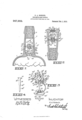
- Figure 1 represents a portion of a bottle in longitudinal section with my non-refilling attachment secured in the neck thereof, the bottle being in the upright position.
- Fig. 2 represents a longitudinal sectional view of the neck of the bottle with my invention applied, the neck being shown in the inverted position.
- Fig. 3 represents an enlarged de' tailed perspective view of the attachment which I provide to be placed in the neck of the bottle.
- Fig. .t is an enlarged detailed perspective view of one of the arms extend ing from the upper plate of the cage.
- 1 represents the body of a bottle of which 2 is the neck, and 3 the stopper or cork.
- Thelip 4 represents an enlargement formed at the 1 sets of downwardly extending lips 10 and r 11, respectively, those 10 and those 11 being spaced at equal intervals around the circumference of the plate, the lips 11 being situated so that they appear in each instance but a short distance from one of the lipslO.
- Thelips 11 have three transverse slits 11 formed therein and the lips 10 are provided with a central opening 10.
- each spring 12 are flat springs having each an end 12 bent outwardly substantially at right angles to the body portion and they are secured to the plate by inserting and passing the unturned end into and through the slits 11.
- the turned end of each spring passes through the opening 10 being directed from the inner side of the lip outwardly.
- the ends 12 of the springs are depressible inwardly and have no lateral movement as the openings 10 receive them snugly.
- the 13 is a cage formed from an upper circular plate 14 and a lower circular plate 15. These plates are secured to each other and to the central plate by the following construction.
- the plate 14-. is provided with four downwardly extending arms 16 which have the upper portion 16 thereof considerably wider than the lower portions 16 so that a shoulder is formed at 16 on each of them.
- the plate 15 has four upwardly directed arms 18 similar to those 16 which have the lower portions 18 thereof considerably wider than the upper portions 18 so that a shoulder is formed similar to that 16 on the arms 16, which shoulders in each case abut the under face of the plate 8 directly to the side of the openings 19 therein, the openings being of a size to receive snugly the upper ends 18 of the arms. It will be understood that the openings 19 and 17 are spaced at equal distances in the plate 8 and are alternately arranged.
- the plates 14 and 15 are also each provided with four openings which are designed to receive the ends of the arms 16 and 19, respectively, the ends of the arms passing through the openings and being turned downwardly against the face of the adjoining plate. In this way the plates 14 and 15 are secured to each other and held in a definite relation to the plate 8, each being prevented from movement away from the plate by the shoulders on the arms of the opposite one, and from movement toward the plate by the shoulders on its arms.
- the plate 15 is provided with an upwardly turned edge 20 formed from lips, the purpose of which will later become apparent.
- valve 23 is a weighted valve having its face 23 formed to fit the valve seat. The valve is free to slide on the rod 21 which passes centrally through it.
- the spring 24 is an arched fiat spring threaded on the rod and having its upper end bearing against the under face of the plate 15 and its lower end against the upper face of the valve 23.
- the spring has a slight play allowed its lower end by the opening 25 being slightly elongated. It is to be understood that the opening in the opposite end of the spring through which the rod passes is of a size just sutlicient to receive the rod.
- 26 is a floating valve free to slide on the rod 21 between the ends of the spring.
- Bottles of this class have been refilled by inverting them and inserting the neck in the liquid and at the same time withdrawing the air from the bottle thus forcing the liquid into the bottle by atmospheric pressure. If one try to fill my bottle in this manner they will find it impossible, as, as soon as the rising liquid reaches the floating valve it passes upwardly with it and in its upward passage carries or forces the valve 23 with it so that prior to the liquid reaching the opening 6 the valve 23 has seated. In pouring the liquid from the bottle it passes through the opening 6 to the plate 8 and through the opening 9 where it escapes to the exterior over the plate 14.
- a non-refillable bottle the combination with the neck of a bottle having an enlargement therein forming a valve seat, of an annular plate adapted to pass and be permanently secured within the neck; a cage carried by the plate and protecting the opening therein; a downwardly extending rod secured to the cage and passing through the opening; and a spring pressed valve slidably secured on the rod and normally seated on the valve seat, as and for the purpose specified.
- a non-refillable bottle the combination with a bottle having an internal enlargement in the neck thereof, said enlargement forming a valve seat, of a plate adapted to enter the neck and be permanently secured therein, said plate being provided with a central opening; a cage carried by the plate and extending above and below the same, said cage surrounding the opening in the plate; a rod secured to the cage and passing downwardly through the opening in the plate; a valve slidable on the rod and adapted to seat on the valve seat; and a spring having its upper end engaging with the under face of the ca e, and its lower end with the upper face of the valve, as and for the purpose specified.
- a non-refillable bottle the combination with a bottle having an internal enlargement in the neck thereof and at the base, of a main plate having a central opening therein said plate being adapted to pass tightly within the neck and being permanently secured therein; a cage consisting in plates disposed above and below the main plate, and spaced and supported therefrom by arms, said plates being directly above and below the opening in the main plate; a rod extending downwardly from the cage; a valve slidably secured to the rod and adapted to seat 011 the valve seat; and a spring having its upper end bearing against the under face of the lower plate of the cage and its lower end engaging with the upper face of the valve, as and for the purpose specified.
- a non-refillable bottle the combination with a bottle having an internal enlargement in the neck thereof and at the base, of a main plate having a central open ing therein, said plate being adapted topass tightly within the neck and being perinanently secured therein; a cage consisting of plates disposed above and below the main plate, and spaced and supported therefrom by arms, said plates being directly above and below the opening in the main plate; a rod secured to the cage and passing downwardly within the neck; a spider at the lower end of the rod fit-ting against the inner wall of the enlargement; a weighted valve slidably secured on the rod; a flat arched spring interposed between the upper face of the valve and the under plate of the cage, said spring having openings in its ends through which the rod passes, the upper opening fitting the rod tightly, and the lower opening loosely, as and. for the purpose specified.
- a non-refillable bottle the combination with a bottle having an interior enlargement within the neck and at the base, said enlargement forming a valve seat, of a main plate adapted to pass tightly within the neck and be permanently secured therein, said plate being provided with a central opening; a cage secured to the main plate and consisting in upper and lower plates having arms extending therefrom, the arms of each plate passing through openings pro vided in the main plate and being secured at their ends to the opposing plate, said arms having further shoulders formed thereon abutting the main plate whereby the cage plates are spaced apart; a rod secured to the cage and passing downwardly within the neck; a spider at the end of the rod fitting the interior wall of the enlargement; a valve on the rod adapted to seat 011 the valve seat;
- a non-refillable bottle the combination with a bottle having an interior enlargement within the neck and at the base, of a main plate adapted to pass within the neck and be permanently secured therein, said tit plate having a central opening; a cage carried by the plate, said cage consisting in an opposing set of plates of larger dimension than the opening in the main plate, said plates being supported from the main plate, the one above and the other below, by arms extending from the plates and passing through openings provided in the main plate, the arms of each plate being spaced apart and secured at their ends to the other plate; shoulders on the arms abutting the main plate; and upwardly directed lips extending from the outer edge of the lower plate, as and for the purpose specified.
- a non-refillable bottle having an in terior enlargement at the base of the neck thereof forming a valve seat, and a horizontally disposed groove within the neck and above the base, a plate adapted to pass within the neck and having a central opening therein, and being provided with clownwa-rdly extending lips having transverse slits therein; and depressible springs having each one of their ends secured to the lips by passing into and through the slits, and the other of their ends turned outwardly, the outwardly turned ends being adapted to pass within the groove when the plate is brought to position within the neck, as and for the purpose specified.
- a plate adapted to pass within the neck and having a central opening therein and being provided with adjoining pairs of downwardly extending lips, one lip of each pair having transverse slits therein and the other an opening therethrough; depressible springs having each one of their ends passing into and through the slits and the other end turned outwardly and directed through the opening in the adjoining lip, said outwardly turned ends being adapted to pass within the groove when the plate is brought to position within the neck, as and for the purpose specified.
- a non-refillable bottle the combination with a bottle having an interior enlargement therein at the base of the neck forming a valve seat, a main plate within the neck having an opening therein; a cage carried by the main plate, and a rod extending downwardly from the cage, of a spring pressed weighted valve slidably held on the rod and adapted to seat on the valve seat; and a floating valve slidable on the rod and above the former valve, as and for the purpose specified.
- a non-refillable bottle the combination with the neck of a bottle having an interior enlargement at the base thereof forming a valve seat, of a plate adapted to pass within the neck and being permanently secured therein, said plate being provided with a central opening; a cage carried by the plate; a rod extending downwardly from the cage; a weighted valve slidable' 0n the rod; an arched spring secured to the rod and bearing at its ends against the under face of the cage and the upper face of the valve, respectively, and a floating valve slidable on the rod and interposed between the 10 ends of the spring, as and for the purpose specified.
Landscapes
- Engineering & Computer Science (AREA)
- Mechanical Engineering (AREA)
- Closures For Containers (AREA)
Description
G. A. ROBERTS, N ON -BEFILLABLE BOTTLE.
APPLICATION FILED MAR. 30, 1909.
y figu Patented Feb, 1,1910.
WNUENTUF? G.A,fQgnFaeavjKs mmay NON-REFILLABLE BOTTLE.
Specification of Letters Patent.
Patented Feb. 1, 1916.
Application filed March 30, 1909. Serial No. 486,688.
To all whom it may concern:
Be it known that I, GEORGE AnnLoR Ronnn'rs, of the city of Winnipeg, in the Province of Manitoba, Canada, have invented certain new and useful Improvements in Non-Refillable Bottles, of which the following is the specification.
My invention relates to non-refillable bottles, and the object of the invention is to provide a bottle which cannot be refilled and from which liquid can be poured readily when desired.
A secondary object is to provide the parts which are inserted in the neck of the bottle so that they can be easily placed in position, and when once in position cannot be withdrawn, and also to constructsuch parts at moderate cost and with little workmanship.
It consists essentially in a bottle having a valve seat formed in the neck thereof and a groove within the neck above the valve seat; an annular supporting plate having springs secured thereto designed to pass within the groove, a protecting cage carried by the plate, a vertical rod secured to the cage and having at its lower end a spider adapted to enter the opening continuous with the valve seat, an arched'spring on the rod and beneath the cage, and a weighted valve and a float valve on the rod, the weighted valve fitting the valve seat, the parts being an ranged and constructed as hereinafter more particularly described.
Figure 1 represents a portion of a bottle in longitudinal section with my non-refilling attachment secured in the neck thereof, the bottle being in the upright position. 1 Fig. 2 represents a longitudinal sectional view of the neck of the bottle with my invention applied, the neck being shown in the inverted position. Fig. 3 represents an enlarged de' tailed perspective view of the attachment which I provide to be placed in the neck of the bottle. Fig. .t is an enlarged detailed perspective view of one of the arms extend ing from the upper plate of the cage.
In the drawings like characters of referfigure.
1 represents the body of a bottle of which 2 is the neck, and 3 the stopper or cork.
4 represents an enlargement formed at the 1 sets of downwardly extending lips 10 and r 11, respectively, those 10 and those 11 being spaced at equal intervals around the circumference of the plate, the lips 11 being situated so that they appear in each instance but a short distance from one of the lipslO. Thelips 11 have three transverse slits 11 formed therein and the lips 10 are provided with a central opening 10.
12 are flat springs having each an end 12 bent outwardly substantially at right angles to the body portion and they are secured to the plate by inserting and passing the unturned end into and through the slits 11. The turned end of each spring passes through the opening 10 being directed from the inner side of the lip outwardly. According to this construction the ends 12 of the springs are depressible inwardly and have no lateral movement as the openings 10 receive them snugly.
13 is a cage formed from an upper circular plate 14 and a lower circular plate 15. These plates are secured to each other and to the central plate by the following construction. The plate 14-. is provided with four downwardly extending arms 16 which have the upper portion 16 thereof considerably wider than the lower portions 16 so that a shoulder is formed at 16 on each of them. a
17 are four openings in the plate 8 adapted to receive the lower or narrow portion of the arms 16. The shoulders 16 in this way abut the upper face of the plate 8. The plate 15 has four upwardly directed arms 18 similar to those 16 which have the lower portions 18 thereof considerably wider than the upper portions 18 so that a shoulder is formed similar to that 16 on the arms 16, which shoulders in each case abut the under face of the plate 8 directly to the side of the openings 19 therein, the openings being of a size to receive snugly the upper ends 18 of the arms. It will be understood that the openings 19 and 17 are spaced at equal distances in the plate 8 and are alternately arranged. The plates 14 and 15 are also each provided with four openings which are designed to receive the ends of the arms 16 and 19, respectively, the ends of the arms passing through the openings and being turned downwardly against the face of the adjoining plate. In this way the plates 14 and 15 are secured to each other and held in a definite relation to the plate 8, each being prevented from movement away from the plate by the shoulders on the arms of the opposite one, and from movement toward the plate by the shoulders on its arms. The plate 15 is provided with an upwardly turned edge 20 formed from lips, the purpose of which will later become apparent.
21 is a rod secured at its upper end to the plate 14 and passing centrally through the opening 9, the lower end being provided with a spider 22 which is adapted to fit within the opening 6 thereby preventing the rod from lateral displacement.
23 is a weighted valve having its face 23 formed to fit the valve seat. The valve is free to slide on the rod 21 which passes centrally through it.
24 is an arched fiat spring threaded on the rod and having its upper end bearing against the under face of the plate 15 and its lower end against the upper face of the valve 23. The spring has a slight play allowed its lower end by the opening 25 being slightly elongated. It is to be understood that the opening in the opposite end of the spring through which the rod passes is of a size just sutlicient to receive the rod.
26 is a floating valve free to slide on the rod 21 between the ends of the spring.
By the construction described above it will be seen that all the operating parts of the device are secured to or carried by the plate 8 which is inserted in the neck of the bottle after the ends 12 of the springs have been pressed inwardly. As soon as the springs are opposite the groove the ends 12 spring out into the groove and in so doing lock the plate in a set position. The spider 22 is then within the opening 6.
To understand the invention I will now describe the operation of the valves in various positions of the bottle, assuming the bottle filled with liquid in the first instance. When the bottle is being inverted and comes to the horizontal position the valve 23 remains closed by virtue of the spring pressure. As it is turned completely to the inverted position the pressure of the liquid and the weight of the valve itself overcomes the pressure of the spring and the liquid flows from the bottle, provided the cork be withdrawn. The flowing of the liquid will not affect the float valve when this operation is taking place. It is impossible to tamper with the valves with a wire or such like as its passage to the valve would be prevented by the cage.
The advantage of the floating valve is now explained. Bottles of this class have been refilled by inverting them and inserting the neck in the liquid and at the same time withdrawing the air from the bottle thus forcing the liquid into the bottle by atmospheric pressure. If one try to fill my bottle in this manner they will find it impossible, as, as soon as the rising liquid reaches the floating valve it passes upwardly with it and in its upward passage carries or forces the valve 23 with it so that prior to the liquid reaching the opening 6 the valve 23 has seated. In pouring the liquid from the bottle it passes through the opening 6 to the plate 8 and through the opening 9 where it escapes to the exterior over the plate 14.
hat I claim as my invention is:
1. In a non-refillable bottle, the combination with the neck of a bottle having an enlargement therein forming a valve seat, of an annular plate adapted to pass and be permanently secured within the neck; a cage carried by the plate and protecting the opening therein; a downwardly extending rod secured to the cage and passing through the opening; and a spring pressed valve slidably secured on the rod and normally seated on the valve seat, as and for the purpose specified.
2. In a non-refillable bottle, the combination with a bottle having an internal enlargement in the neck thereof, said enlargement forming a valve seat, of a plate adapted to enter the neck and be permanently secured therein, said plate being provided with a central opening; a cage carried by the plate and extending above and below the same, said cage surrounding the opening in the plate; a rod secured to the cage and passing downwardly through the opening in the plate; a valve slidable on the rod and adapted to seat on the valve seat; and a spring having its upper end engaging with the under face of the ca e, and its lower end with the upper face of the valve, as and for the purpose specified.
3. In a non-refillable bottle, the combination with a bottle having an internal enlargement in the neck thereof and at the base, of a main plate having a central opening therein said plate being adapted to pass tightly within the neck and being permanently secured therein; a cage consisting in plates disposed above and below the main plate, and spaced and supported therefrom by arms, said plates being directly above and below the opening in the main plate; a rod extending downwardly from the cage; a valve slidably secured to the rod and adapted to seat 011 the valve seat; and a spring having its upper end bearing against the under face of the lower plate of the cage and its lower end engaging with the upper face of the valve, as and for the purpose specified.
4t. In a non-refillable bottle, the combination with a bottle having an internal enlargement in the neck thereof and at the base, of a main plate having a central open ing therein, said plate being adapted topass tightly within the neck and being perinanently secured therein; a cage consisting of plates disposed above and below the main plate, and spaced and supported therefrom by arms, said plates being directly above and below the opening in the main plate; a rod secured to the cage and passing downwardly within the neck; a spider at the lower end of the rod fit-ting against the inner wall of the enlargement; a weighted valve slidably secured on the rod; a flat arched spring interposed between the upper face of the valve and the under plate of the cage, said spring having openings in its ends through which the rod passes, the upper opening fitting the rod tightly, and the lower opening loosely, as and. for the purpose specified.
5. In a non-refillable bottle, the combination with a bottle having an interior enlargement within the neck and at the base, said enlargement forming a valve seat, of a main plate adapted to pass tightly within the neck and be permanently secured therein, said plate being provided with a central opening; a cage secured to the main plate and consisting in upper and lower plates having arms extending therefrom, the arms of each plate passing through openings pro vided in the main plate and being secured at their ends to the opposing plate, said arms having further shoulders formed thereon abutting the main plate whereby the cage plates are spaced apart; a rod secured to the cage and passing downwardly within the neck; a spider at the end of the rod fitting the interior wall of the enlargement; a valve on the rod adapted to seat 011 the valve seat;
and an arched spring secured to the rod at its ends and bearing against the lower face of the valve and the under face of the cage, as and for the purpose specified.
(3. In a non-refillable bottle, the combination with a bottle having an interior enlargement within the neck and at the base, of a main plate adapted to pass within the neck and be permanently secured therein, said tit plate having a central opening; a cage carried by the plate, said cage consisting in an opposing set of plates of larger dimension than the opening in the main plate, said plates being supported from the main plate, the one above and the other below, by arms extending from the plates and passing through openings provided in the main plate, the arms of each plate being spaced apart and secured at their ends to the other plate; shoulders on the arms abutting the main plate; and upwardly directed lips extending from the outer edge of the lower plate, as and for the purpose specified.
7. In a non-refillable bottle having an in terior enlargement at the base of the neck thereof forming a valve seat, and a horizontally disposed groove within the neck and above the base, a plate adapted to pass within the neck and having a central opening therein, and being provided with clownwa-rdly extending lips having transverse slits therein; and depressible springs having each one of their ends secured to the lips by passing into and through the slits, and the other of their ends turned outwardly, the outwardly turned ends being adapted to pass within the groove when the plate is brought to position within the neck, as and for the purpose specified.
8. In a non-refillable bottle having an interior enlargement at the base of the neck thereof forming a valve seat, and a horizontally disposed groove within the neck and above the base, a plate adapted to pass within the neck and having a central opening therein and being provided with adjoining pairs of downwardly extending lips, one lip of each pair having transverse slits therein and the other an opening therethrough; depressible springs having each one of their ends passing into and through the slits and the other end turned outwardly and directed through the opening in the adjoining lip, said outwardly turned ends being adapted to pass within the groove when the plate is brought to position within the neck, as and for the purpose specified.
9. In a non-refillable bottle, the combination with a bottle having an interior enlargement therein at the base of the neck forming a valve seat, a main plate within the neck having an opening therein; a cage carried by the main plate, and a rod extending downwardly from the cage, of a spring pressed weighted valve slidably held on the rod and adapted to seat on the valve seat; and a floating valve slidable on the rod and above the former valve, as and for the purpose specified.
10. In a non-refillable bottle, the combination with the neck of a bottle having an interior enlargement at the base thereof forming a valve seat, of a plate adapted to pass within the neck and being permanently secured therein, said plate being provided with a central opening; a cage carried by the plate; a rod extending downwardly from the cage; a weighted valve slidable' 0n the rod; an arched spring secured to the rod and bearing at its ends against the under face of the cage and the upper face of the valve, respectively, and a floating valve slidable on the rod and interposed between the 10 ends of the spring, as and for the purpose specified.
Signed at Vinnipeg, in the Province of Manitoba, this 20th day of January 1909.
GEORGE ADELOR ROBERTS. In the presence of G. S. ROXBURGH, M. A. SOMERVILLE.
Priority Applications (1)
| Application Number | Priority Date | Filing Date | Title |
|---|---|---|---|
| US48668809A US947852A (en) | 1909-03-30 | 1909-03-30 | Non-refillable bottle. |
Applications Claiming Priority (1)
| Application Number | Priority Date | Filing Date | Title |
|---|---|---|---|
| US48668809A US947852A (en) | 1909-03-30 | 1909-03-30 | Non-refillable bottle. |
Publications (1)
| Publication Number | Publication Date |
|---|---|
| US947852A true US947852A (en) | 1910-02-01 |
Family
ID=3016270
Family Applications (1)
| Application Number | Title | Priority Date | Filing Date |
|---|---|---|---|
| US48668809A Expired - Lifetime US947852A (en) | 1909-03-30 | 1909-03-30 | Non-refillable bottle. |
Country Status (1)
| Country | Link |
|---|---|
| US (1) | US947852A (en) |
-
1909
- 1909-03-30 US US48668809A patent/US947852A/en not_active Expired - Lifetime
Similar Documents
| Publication | Publication Date | Title |
|---|---|---|
| US920184A (en) | Non-refillable bottle. | |
| US971916A (en) | Non-refillable bottle. | |
| US820100A (en) | Non-refillable bottle. | |
| US788644A (en) | Non-refillable bottle. | |
| US890399A (en) | Non-refillable-bottle stopper. | |
| US979998A (en) | Non-refillable bottle. | |
| US1111046A (en) | Non-refillable bottle. | |
| US1130488A (en) | Protective bottle. | |
| US944015A (en) | Non-refillable bottle. | |
| US1102223A (en) | Non-refillable bottle. | |
| US1130183A (en) | Bottle-closure. | |
| US840453A (en) | Non-refillable bottle. | |
| US1031619A (en) | Non-refillable bottle. | |
| US774617A (en) | Non-refillable bottle. | |
| US1053905A (en) | Bottle. | |
| US838035A (en) | Non-refillable bottle. | |
| US1046670A (en) | Non-refillable bottle. | |
| US1131400A (en) | Bottle-stopper. | |
| US1072497A (en) | Non-refillable bottle. | |
| US921009A (en) | Non-refillable bottle. | |
| US1148503A (en) | Non-refillable bottle. | |
| US745552A (en) | Non-refillable bottle. | |
| US716657A (en) | Non-refillable bottle. | |
| US1047732A (en) | Non-refillable bottle. | |
| US566720A (en) | Device for preventing bottle-refilling |