US9470900B2 - Display unit, display driving circuit, and display driving method - Google Patents
Display unit, display driving circuit, and display driving method Download PDFInfo
- Publication number
- US9470900B2 US9470900B2 US13/943,022 US201313943022A US9470900B2 US 9470900 B2 US9470900 B2 US 9470900B2 US 201313943022 A US201313943022 A US 201313943022A US 9470900 B2 US9470900 B2 US 9470900B2
- Authority
- US
- United States
- Prior art keywords
- driving
- pixels
- display
- group
- period
- Prior art date
- Legal status (The legal status is an assumption and is not a legal conclusion. Google has not performed a legal analysis and makes no representation as to the accuracy of the status listed.)
- Active, expires
Links
Images


Classifications
-
- G02B27/2264—
-
- G—PHYSICS
- G09—EDUCATION; CRYPTOGRAPHY; DISPLAY; ADVERTISING; SEALS
- G09G—ARRANGEMENTS OR CIRCUITS FOR CONTROL OF INDICATING DEVICES USING STATIC MEANS TO PRESENT VARIABLE INFORMATION
- G09G3/00—Control arrangements or circuits, of interest only in connection with visual indicators other than cathode-ray tubes
- G09G3/001—Control arrangements or circuits, of interest only in connection with visual indicators other than cathode-ray tubes using specific devices not provided for in groups G09G3/02 - G09G3/36, e.g. using an intermediate record carrier such as a film slide; Projection systems; Display of non-alphanumerical information, solely or in combination with alphanumerical information, e.g. digital display on projected diapositive as background
- G09G3/003—Control arrangements or circuits, of interest only in connection with visual indicators other than cathode-ray tubes using specific devices not provided for in groups G09G3/02 - G09G3/36, e.g. using an intermediate record carrier such as a film slide; Projection systems; Display of non-alphanumerical information, solely or in combination with alphanumerical information, e.g. digital display on projected diapositive as background to produce spatial visual effects
-
- G—PHYSICS
- G02—OPTICS
- G02B—OPTICAL ELEMENTS, SYSTEMS OR APPARATUS
- G02B30/00—Optical systems or apparatus for producing three-dimensional [3D] effects, e.g. stereoscopic images
- G02B30/20—Optical systems or apparatus for producing three-dimensional [3D] effects, e.g. stereoscopic images by providing first and second parallax images to an observer's left and right eyes
- G02B30/22—Optical systems or apparatus for producing three-dimensional [3D] effects, e.g. stereoscopic images by providing first and second parallax images to an observer's left and right eyes of the stereoscopic type
- G02B30/24—Optical systems or apparatus for producing three-dimensional [3D] effects, e.g. stereoscopic images by providing first and second parallax images to an observer's left and right eyes of the stereoscopic type involving temporal multiplexing, e.g. using sequentially activated left and right shutters
-
- G—PHYSICS
- G09—EDUCATION; CRYPTOGRAPHY; DISPLAY; ADVERTISING; SEALS
- G09G—ARRANGEMENTS OR CIRCUITS FOR CONTROL OF INDICATING DEVICES USING STATIC MEANS TO PRESENT VARIABLE INFORMATION
- G09G3/00—Control arrangements or circuits, of interest only in connection with visual indicators other than cathode-ray tubes
- G09G3/20—Control arrangements or circuits, of interest only in connection with visual indicators other than cathode-ray tubes for presentation of an assembly of a number of characters, e.g. a page, by composing the assembly by combination of individual elements arranged in a matrix no fixed position being assigned to or needed to be assigned to the individual characters or partial characters
- G09G3/34—Control arrangements or circuits, of interest only in connection with visual indicators other than cathode-ray tubes for presentation of an assembly of a number of characters, e.g. a page, by composing the assembly by combination of individual elements arranged in a matrix no fixed position being assigned to or needed to be assigned to the individual characters or partial characters by control of light from an independent source
- G09G3/3406—Control of illumination source
-
- G—PHYSICS
- G09—EDUCATION; CRYPTOGRAPHY; DISPLAY; ADVERTISING; SEALS
- G09G—ARRANGEMENTS OR CIRCUITS FOR CONTROL OF INDICATING DEVICES USING STATIC MEANS TO PRESENT VARIABLE INFORMATION
- G09G3/00—Control arrangements or circuits, of interest only in connection with visual indicators other than cathode-ray tubes
- G09G3/20—Control arrangements or circuits, of interest only in connection with visual indicators other than cathode-ray tubes for presentation of an assembly of a number of characters, e.g. a page, by composing the assembly by combination of individual elements arranged in a matrix no fixed position being assigned to or needed to be assigned to the individual characters or partial characters
- G09G3/34—Control arrangements or circuits, of interest only in connection with visual indicators other than cathode-ray tubes for presentation of an assembly of a number of characters, e.g. a page, by composing the assembly by combination of individual elements arranged in a matrix no fixed position being assigned to or needed to be assigned to the individual characters or partial characters by control of light from an independent source
- G09G3/36—Control arrangements or circuits, of interest only in connection with visual indicators other than cathode-ray tubes for presentation of an assembly of a number of characters, e.g. a page, by composing the assembly by combination of individual elements arranged in a matrix no fixed position being assigned to or needed to be assigned to the individual characters or partial characters by control of light from an independent source using liquid crystals
- G09G3/3607—Control arrangements or circuits, of interest only in connection with visual indicators other than cathode-ray tubes for presentation of an assembly of a number of characters, e.g. a page, by composing the assembly by combination of individual elements arranged in a matrix no fixed position being assigned to or needed to be assigned to the individual characters or partial characters by control of light from an independent source using liquid crystals for displaying colours or for displaying grey scales with a specific pixel layout, e.g. using sub-pixels
-
- G—PHYSICS
- G09—EDUCATION; CRYPTOGRAPHY; DISPLAY; ADVERTISING; SEALS
- G09G—ARRANGEMENTS OR CIRCUITS FOR CONTROL OF INDICATING DEVICES USING STATIC MEANS TO PRESENT VARIABLE INFORMATION
- G09G3/00—Control arrangements or circuits, of interest only in connection with visual indicators other than cathode-ray tubes
- G09G3/20—Control arrangements or circuits, of interest only in connection with visual indicators other than cathode-ray tubes for presentation of an assembly of a number of characters, e.g. a page, by composing the assembly by combination of individual elements arranged in a matrix no fixed position being assigned to or needed to be assigned to the individual characters or partial characters
- G09G3/34—Control arrangements or circuits, of interest only in connection with visual indicators other than cathode-ray tubes for presentation of an assembly of a number of characters, e.g. a page, by composing the assembly by combination of individual elements arranged in a matrix no fixed position being assigned to or needed to be assigned to the individual characters or partial characters by control of light from an independent source
- G09G3/36—Control arrangements or circuits, of interest only in connection with visual indicators other than cathode-ray tubes for presentation of an assembly of a number of characters, e.g. a page, by composing the assembly by combination of individual elements arranged in a matrix no fixed position being assigned to or needed to be assigned to the individual characters or partial characters by control of light from an independent source using liquid crystals
- G09G3/3611—Control of matrices with row and column drivers
- G09G3/3648—Control of matrices with row and column drivers using an active matrix
- G09G3/3655—Details of drivers for counter electrodes, e.g. common electrodes for pixel capacitors or supplementary storage capacitors
-
- G—PHYSICS
- G09—EDUCATION; CRYPTOGRAPHY; DISPLAY; ADVERTISING; SEALS
- G09G—ARRANGEMENTS OR CIRCUITS FOR CONTROL OF INDICATING DEVICES USING STATIC MEANS TO PRESENT VARIABLE INFORMATION
- G09G5/00—Control arrangements or circuits for visual indicators common to cathode-ray tube indicators and other visual indicators
- G09G5/10—Intensity circuits
-
- H04N13/0438—
-
- H—ELECTRICITY
- H04—ELECTRIC COMMUNICATION TECHNIQUE
- H04N—PICTORIAL COMMUNICATION, e.g. TELEVISION
- H04N13/00—Stereoscopic video systems; Multi-view video systems; Details thereof
- H04N13/30—Image reproducers
- H04N13/332—Displays for viewing with the aid of special glasses or head-mounted displays [HMD]
- H04N13/341—Displays for viewing with the aid of special glasses or head-mounted displays [HMD] using temporal multiplexing
-
- G—PHYSICS
- G09—EDUCATION; CRYPTOGRAPHY; DISPLAY; ADVERTISING; SEALS
- G09G—ARRANGEMENTS OR CIRCUITS FOR CONTROL OF INDICATING DEVICES USING STATIC MEANS TO PRESENT VARIABLE INFORMATION
- G09G2300/00—Aspects of the constitution of display devices
- G09G2300/04—Structural and physical details of display devices
- G09G2300/0439—Pixel structures
-
- G—PHYSICS
- G09—EDUCATION; CRYPTOGRAPHY; DISPLAY; ADVERTISING; SEALS
- G09G—ARRANGEMENTS OR CIRCUITS FOR CONTROL OF INDICATING DEVICES USING STATIC MEANS TO PRESENT VARIABLE INFORMATION
- G09G2300/00—Aspects of the constitution of display devices
- G09G2300/04—Structural and physical details of display devices
- G09G2300/0469—Details of the physics of pixel operation
- G09G2300/0478—Details of the physics of pixel operation related to liquid crystal pixels
- G09G2300/0495—Use of transitions between isotropic and anisotropic phases in liquid crystals, by voltage controlled deformation of the liquid crystal molecules, as opposed to merely changing the orientation of the molecules as in, e.g. twisted-nematic [TN], vertical-aligned [VA], cholesteric, in-plane, or bi-refringent liquid crystals
-
- G—PHYSICS
- G09—EDUCATION; CRYPTOGRAPHY; DISPLAY; ADVERTISING; SEALS
- G09G—ARRANGEMENTS OR CIRCUITS FOR CONTROL OF INDICATING DEVICES USING STATIC MEANS TO PRESENT VARIABLE INFORMATION
- G09G2320/00—Control of display operating conditions
- G09G2320/02—Improving the quality of display appearance
- G09G2320/0209—Crosstalk reduction, i.e. to reduce direct or indirect influences of signals directed to a certain pixel of the displayed image on other pixels of said image, inclusive of influences affecting pixels in different frames or fields or sub-images which constitute a same image, e.g. left and right images of a stereoscopic display
Definitions
- the present disclosure relates to a display unit for displaying images, as well as a display driving circuit and a display driving method that are in use for such a display unit.
- display systems capable of achieving a stereoscopic display have been attracting attention.
- One of such display systems is a display system using shutter glasses.
- this display system left-eye images and right-eye images with parallax components with respect to each other are alternately displayed on a display unit in a time-divisional manner, and at the same time, an opening/closing motion of a left-eye shutter and a right-eye shutter of shutter glasses is controlled to be switched in synchronization with switching of those images.
- Such a switching operation is performed repeatedly, which allows viewers to perceive an image composed of those series of images as a stereoscopic image with an appearance of depth.
- a display unit including: a display section having a plurality of pixels in a first group and a plurality of pixels in a second group, and performing a display operation by switching a display based on a first type of frame image during a first period and a display based on a second type of frame image during a second period; and a driving section performing a first driving to drive the plurality of pixels in the first group without driving the plurality of pixels in the second group during the first period, and performing a second driving to drive the plurality of pixels in the second group without driving the plurality of pixels in the first group during the second period.
- a display driving circuit including: a driving section performing a first driving to drive a plurality of pixels in a first group without driving a plurality of pixels in a second group during a first period, and performing a second driving to drive the plurality of pixels in the second group without driving the plurality of pixels in the first group during a second period for a display section having the plurality of pixels in the first group and the plurality of pixels in the second group, the display section performing a display operation by switching a display based on a first type of frame image during the first period and a display based on a second type of frame image during the second period.
- a display driving method including: preparing a first type of frame image and a second type of frame image; and performing a display operation by switching a display based on the first type of frame image during a first period and a display based on the second type of frame image during a second period by performing a first driving to drive a plurality of pixels in a first group without driving a plurality of pixels in a second group during the first period and by performing a second driving to drive the plurality of pixels in the second group without driving the plurality of pixels in the first group during the second period.
- a display operation is carried out by switching a display based on a first type of frame image during a first period and a display based on a second type of frame image during a second period.
- a plurality of pixels in a first group are driven without driving a plurality of pixels in a second group during the first period
- the plurality of pixels in the second group are driven without driving the plurality of pixels in the first group during the second period.
- a plurality of pixels in a first group are driven without driving a plurality of pixels in a second group during a first period
- the plurality of pixels in the second group are driven without driving the plurality of pixels in the first group during a second period, which allows the image quality to be enhanced.
- FIG. 1 is a block diagram showing a configuration example of a display system according to an embodiment of the present disclosure.
- FIG. 2 is a block diagram showing a configuration example of a display driving section illustrated in FIG. 1 .
- FIG. 3 is an explanatory diagram showing a pixel arrangement on a liquid crystal display section according to a first embodiment of the present disclosure.
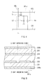
- FIG. 4 is a circuit diagram showing a configuration example of the sub-pixel illustrated in FIG. 3 .
- FIG. 5 is a cross-sectional diagram showing a schematic cross-sectional structure of a liquid crystal display section illustrated in FIG. 1 .
- FIG. 6A is an explanatory diagram showing an operation example in the case of a display of a left-eye image.
- FIG. 6B is an explanatory diagram showing an operation example in the case of a display of a right-eye image.
- FIG. 7 are each a timing waveform chart showing an operation example of the display system illustrated in FIG. 1 .
- FIG. 8 is a table showing an operation example of the display system illustrated in FIG. 1 .
- FIG. 9 are each a timing waveform chart showing an operation example of the sub-pixel illustrated in FIG. 4 .
- FIGS. 10A and 10B are each a schematic diagram showing an operation example of the liquid crystal display section illustrated in FIG. 1 .
- FIG. 11A is a timing waveform chart showing an operation example of a sub-pixel belonging to an odd-numbered line.
- FIG. 11B is a timing waveform chart showing an operation example of a sub-pixel belonging to an even-numbered line.
- FIG. 12 are each a timing waveform chart showing an operation example of a display system according to a comparative example 1.
- FIG. 13 is a table showing an operation example of the display system illustrated in FIG. 12 .
- FIG. 14 is a timing waveform chart showing an operation example of a sub-pixel according to the display system illustrated in FIG. 12 .
- FIG. 15 are each a timing waveform chart showing an operation example of a display system according to a comparative example 2.
- FIG. 16 is a table showing an operation example of the display system illustrated in FIG. 15 .
- FIG. 17A is a timing waveform chart showing an operation example of a sub-pixel belonging to an odd-numbered line according to the display system illustrated in FIG. 15 .
- FIG. 17B is a timing waveform chart showing an operation example of a sub-pixel belonging to an even-numbered line according to the display system illustrated in FIG. 15 .
- FIG. 18 is a table showing an operation example of a display system according to a modification example of the first embodiment.
- FIG. 19 are each a timing waveform chart showing an operation example of a display system according to another modification example of the first embodiment.
- FIG. 20 is a table showing an operation example of the display system illustrated in FIG. 19 .
- FIG. 21 are each a timing waveform chart showing an operation example of a display system according to still another modification example of the first embodiment.
- FIG. 22 is a table showing an operation example of the display system illustrated in FIG. 21 .
- FIG. 23 are each a timing waveform chart showing an operation example of a display system according to still another modification example of the first embodiment.
- FIG. 24 is a table showing an operation example of the display system illustrated in FIG. 23 .
- FIG. 25 are each a timing waveform chart showing an operation example of a display system according to still another modification example of the first embodiment.
- FIG. 26 is a table showing an operation example of the display system illustrated in FIG. 25 .
- FIG. 27 are each a timing waveform chart showing an operation example of a display system according to still another modification example of the first embodiment.
- FIG. 28 is a table showing an operation example of the display system illustrated in FIG. 27 .
- FIG. 29 are each a timing waveform chart showing an operation example of a display system according to still another modification example of the first embodiment.
- FIG. 30 is a table showing an operation example of the display system illustrated in FIG. 29 .
- FIG. 31 is an explanatory diagram showing a pixel arrangement on a liquid crystal display section according to a second embodiment of the present disclosure.
- FIG. 32 is an explanatory diagram showing a pixel arrangement on a liquid crystal display section according to a modification example of the second embodiment.
- FIG. 33 is an explanatory diagram showing a pixel arrangement on a liquid crystal display section according to another modification example of the second embodiment.
- FIG. 34 is an explanatory diagram showing a pixel arrangement on a liquid crystal display section according to still another modification example of the second embodiment o.
- FIG. 35 is a block diagram showing a configuration example of a display system according to a third embodiment of the present disclosure.
- FIG. 36A is an explanatory diagram showing an operation example of the display system illustrated in FIG. 35 .
- FIG. 36B is an explanatory diagram showing another operation example of the display system illustrated in FIG. 35 .
- FIG. 37 are each a timing waveform chart showing an operation example of the display system illustrated in FIG. 35 .
- FIG. 38 is a table showing an operation example of the display system illustrated in FIG. 35 .
- FIG. 39 is a perspective view showing an external appearance of a television receiver to which the display system according to any of the above-described embodiments is applied.
- FIG. 1 shows a configuration example of a display system 1 according to a first embodiment of the present disclosure.
- the display system 1 is a display system for carrying out a stereoscopic display. It is to be noted that the display driving circuit and the display driving method according to the embodiments of the present disclosure are also described together because they are embodied with this embodiment of the present disclosure.
- the display system 1 includes a display unit 10 and shutter glasses 80 .
- the display unit 10 is provided with an image processing section 11 , a display driving section 20 , a liquid crystal display section 13 , a backlight driving section 14 , a backlight 15 , and a shutter control section 16 .
- the image processing section 11 controls the display driving section 20 , the backlight driving section 14 , and the shutter control section 16 to share a control signal and operate in synchronization with one another.
- the image signal Sdisp includes a series of left-eye images FL and right-eye images FR that are arranged alternately.
- the image processing section 11 also has a capability to insert a black image Bk between each of the left-eye images FL and each of the right-eye images FR. It is to be noted that such a functional assignment is not limited thereto, although instead of this, for example, the display driving section 20 may have the capability to insert the black image Bk, or alternatively a configuration may be adopted which ensures that a series of images including the left-eye image FL, the right-eye image FR, and the black image Bk is input to the image processing section 11 .
- the display driving section 20 drives the liquid crystal display section 13 based on an image signal Sdisp 2 to be provided from the image processing section 11 .
- the liquid crystal display section 13 drives a liquid crystal display device to modulate light that is emitted from the backlight 15 , thereby performing a display.
- the liquid crystal display section 13 is a so-called quad-speed display panel.
- FIG. 2 shows an example of a block diagram for the display driving section 20 .
- the display driving section 20 is provided with a timing control section 21 , a gate driver 22 , and a data driver 23 .
- the timing control section 21 controls drive timing for the gate driver 22 and the data driver 23 , while generating an image signal Sdisp 3 based on the image signal Sdisp 2 to be provided from the image processing section 11 to provide such an image signal Sdisp 3 to the data driver 23 .
- the gate driver 22 sequentially selects pixels Pix within the liquid crystal display section 13 for each row for sequential scanning according to timing control that is performed by the timing control section 21 .
- the data driver 23 provides a pixel voltage Vpix based on the image signal Sdisp 3 to each of the pixels Pix within the liquid crystal display section 13 .
- the data driver 23 generates the pixel voltage Vpix in the form of an analog signal by performing D/A (digital-to-analog) conversion based on the image signal Sdisp 3 to provide such a pixel voltage Vpix to each of the pixels Pix.
- the display driving section 20 drives the liquid crystal display section 13 by performing a sequential scanning.
- the display driving section 20 drives the liquid crystal display section 13 in a manner of performing a sequential scan only on odd-numbered lines in the liquid crystal display section 13 in displaying the left-eye image FL followed by the black image Bk and of performing a sequential scan only on even-numbered lines in the liquid crystal display section 13 in displaying the right-eye image FR followed by the black image Bk.
- FIG. 3 shows a configuration example of the liquid crystal display section 13 .
- the pixels Pix are arrayed in a matrix pattern.
- Each of the pixels Pix has three sub-pixels SPix that correspond to a red color (R), a green color (G), and a blue color (B), respectively.
- the sub-pixels SPix that are arranged side-by-side in a horizontal direction X are connected with the same gate line GCL (to be hereinafter described).
- FIG. 4 shows an example of a circuit diagram for the sub-pixel SPix that configures the pixel Pix.
- the pixel Pix includes a TFT (Thin-Film Transistor) device Tr, a liquid crystal device LC, and a storage capacitor Cs.
- the TFT device Tr may be configured of, for example, a MOS (Metal Oxide Semiconductor) type FET (Field-Effect Transistor) with a gate thereof connected to the gate line GCL, with a source thereof connected to a data line SGL, and with a drain thereof connected to an end of the liquid crystal device LC and an end of the storage capacitor Cs.
- MOS Metal Oxide Semiconductor
- FET Field-Effect Transistor
- a first end thereof is connected with the drain of the TFT device Tr, while a second end thereof is grounded.
- a first end thereof is connected with the drain of the TFT device Tr, while a second end is connected with a storage capacitor line CSL.
- the gate line GCL is connected with the gate driver 22
- the data line SGL is connected with the data driver 23 .
- FIG. 5 shows a cross-sectional structure of the liquid crystal display section 13 .
- the liquid crystal display section 13 has a liquid crystal layer 203 that is sealed between a drive substrate 201 and a facing substrate 205 .
- the drive substrate 201 on which the above-described TFT device Tr and the like (not shown in the figure) are formed, has a pixel electrode 202 that is arranged for each of the sub-pixels SPix thereon.
- a color filter and a black matrix that are not shown in the figure are formed, and further a counter electrode 204 is also arranged as an electrode common to the sub-pixels SPix on the surface at the liquid crystal layer 203 side.
- polarization plates 206 a and 206 b are attached to be placed in a crossed Nicols or a parallel Nicols state.
- the liquid crystal layer 203 which functions as a so-called VA (Vertical Alignment) liquid crystal in this example, may include, for example, liquid crystal molecules M having negative dielectric anisotropy.
- the backlight driving section 14 drives the backlight 15 based on a control signal to be provided from the image processing section 11 . More specifically, the backlight driving section 14 drives the backlight 15 to emit light intermittently in synchronization with a display operation in the liquid crystal display section 13 .
- the backlight 15 has a capability to emit plane emission light to the liquid crystal display section 13 .
- the backlight 15 may be configured using, for example, an LED (Light Emitting Diode), a CCFL (Cold Cathode Fluorescent Lamp), and the like.
- the shutter control section 16 generates a shutter control signal CTL based on a control signal to be provided from the image processing section 11 , and provides such a shutter control signal CTL to the shutter glasses 80 through a wireless communication. It is to be noted that, in this example, the shutter control section 16 provides the shutter control signal CTL through the wireless communication, although a communication method is not limited thereto, and the shutter control signal CTL may be provided through a wired communication.
- a pair of the shutter glasses 80 is an eyeglasses-type shutter device, allowing a viewer (not shown in the figure) to perform a stereoscopic viewing by the use of such a device.
- the shutter glasses 80 have a left-eye shutter 8 L and a right-eye shutter 8 R.
- Each of the left-eye shutter 8 L and the right-eye shutter 8 R may be configured of, for example, a liquid crystal shutter.
- a transmitting state (open state) and a shutoff state (closed state) of each of the left-eye shutter 8 L and the right-eye shutter 8 R are controlled with the shutter control signal CTL that is provided from the shutter control section 16 .
- the liquid crystal display section 13 corresponds to a specific but not limitative example of a “display section” of the present disclosure.
- the display driving section 20 corresponds to a specific but not limitative example of a “driving section” of the present disclosure.
- the gate line GCL corresponds to a specific but not limitative example of a “scanning signal line” of the present disclosure.
- the left-eye image FL corresponds to a specific but not limitative example of a “first type of frame image” of the present disclosure.
- the right-eye image FR corresponds to a specific but not limitative example of a “second type of frame image” of the present disclosure.
- the description is provided on an overview of the overall operation for the display system 1 .
- the image processing section 11 Based on the image signal Sdisp to be provided externally, the image processing section 11 provides a control signal to each of the display driving section 20 , the backlight driving section 14 , and the shutter control section 16 , and controls them to operate in synchronization with one another.
- the backlight driving section 14 drives the backlight 15 based on a control signal to be provided from the image processing section 11 .
- the backlight 15 emits plane emission light to the liquid crystal display section 13 .
- the display driving section 20 drives the liquid crystal display section 13 based on the image signal Sdisp 2 to be provided from the image processing section 11 .
- the liquid crystal display section 13 performs a display by modulating light that is emitted from the backlight 15 .
- the shutter control section 16 generates the shutter control signal CTL based on a control signal to be provided from the image processing section 11 , and provides the shutter control signal CTL to the shutter glasses 80 .
- Each of the left-eye shutter 8 L and the right-eye shutter 8 R of the shutter glasses 80 performs its opening/closing action based on the shutter control signal CTL.
- FIG. 6A and FIG. 6B schematically show an overall operation of the display system 1 .
- FIG. 6A shows an operation in the case of a display of the left-eye image FL
- FIG. 6B shows an operation in the case of a display of the right-eye image FR.
- the display unit 10 displays the left-eye image FL
- the shutter glasses 80 the left-eye shutter 8 L is put in an open state
- the right-eye shutter 8 R is put in a closed state as illustrated in FIG. 6A . Consequently, a viewer 9 views the left-eye image FL with a left eye 9 L.
- the display unit 10 displays the right-eye image FR
- the left-eye shutter 8 L is put in a closed state
- the right-eye shutter 8 R is put in an open state as illustrated in FIG. 6B . Consequently, the viewer 9 views the right-eye image FR with a right eye 9 R.
- parallax exists between the left-eye image FL and the right-eye image FR, this allows the viewer 9 to perceive an image composed of the series of images as a stereoscopic image with an appearance of depth.
- FIG. 7 shows a timing waveform chart for a display operation of the display system 1 , wherein (A), (B), (C), and (D) show operation of the liquid crystal display section 13 , operation of the backlight 15 , operation of the left-eye shutter 8 L of the shutter glasses 80 , and operation of the right-eye shutter 8 R, respectively.
- a vertical axis of (A) of FIG. 7 denotes a scan position in a sequential scanning direction of the liquid crystal display section 13 . Further, in (A) of FIG.
- “FL” indicates that the display driving section 20 performs a display driving based on the left-eye image FL
- “FR” indicates that the display driving section 20 performs a display driving based on the right-eye image FR
- “Bk” indicates that the display driving section 20 performs a display driving based on the black image Bk.
- “ON” indicates that the backlight 15 turns on
- “OFF” indicates that the backlight 15 turns off.
- a sequential scanning is carried out twice on each of the following images in the order of the left-eye image FL, the black image Bk, the right-eye image FR, and the black image Bk.
- a display of those images is repeated during every timing cycle T 0 .
- an operational state is set up for each of eight periods P 1 to P 8 corresponding to a sequential scanning ((A) of FIG. 7 ).
- FIG. 8 shows operation of odd-numbered lines and even-numbered lines in the liquid crystal display section 13 during the periods P 1 to P 8 .
- “FL” indicates that the display driving section 20 performs a display driving based on the left-eye image FL
- “FR” indicates that the display driving section 20 performs a display driving based on the right-eye image FR
- “Bk” indicates that the display driving section 20 performs a display driving based on the black image Bk.
- a symbol “-” indicates that the display driving section 20 performs no display driving operation.
- the display unit 10 displays the left-eye image FL during a timing period of t 0 to t 3 .
- the display driving section 20 performs a first-time sequential scanning based on the left-eye image FL from an uppermost part toward a lowermost part for only the odd-numbered lines of the liquid crystal display section 13 during a timing period of t 0 to t 1 , and performs a second-time sequential scanning based on the left-eye image FL similarly during the following timing period of t 1 to t 3 ((A) of FIG. 7 and FIG. 8 ).
- the display unit 10 displays the black image Bk during a timing period of t 3 to t 7 .
- the display driving section 20 performs a first-time sequential scanning based on the black image Bk from an uppermost part toward a lowermost part for only the odd-numbered lines of the liquid crystal display section 13 during a timing period of t 3 to t 6 , and performs a second-time sequential scanning based on the black image Bk similarly during the following timing period of t 6 to t 7 ((A) of FIG. 7 and FIG. 8 ). This makes it possible to fully reset the sub-pixels SPix on the odd-numbered lines.
- the display unit 10 displays the right-eye image FR during a timing period of t 7 to t 10 .
- the display driving section 20 performs a first-time sequential scanning based on the right-eye image FR from an uppermost part toward a lowermost part for only the even-numbered lines of the liquid crystal display section 13 during a timing period of t 7 to t 8 , and performs a second-time sequential scanning based on the right-eye image FR similarly during the following timing period of t 8 to t 10 ((A) of FIG. 7 and FIG. 8 ).
- the display unit 10 displays the black image Bk during a timing period of t 10 to t 14 .
- the display driving section 20 performs a first-time sequential scanning based on the black image Bk from an uppermost part toward a lowermost part for only the even-numbered lines of the liquid crystal display section 13 during a timing period of t 10 to t 13 , and performs a second-time sequential scanning based on the black image Bk similarly during the following timing period of t 13 to t 14 ((A) of FIG. 7 and FIG. 8 ). This makes it possible to fully reset the sub-pixels SPix on the even-numbered lines.
- the display system 1 carries out a display in a time-divisional manner in the order of the left-eye image FL, the black image Bk, the right-eye image FR, and the black image Bk.
- FIG. 9 represents operation of the sub-pixel SPix, wherein (A) shows a timing waveform of a voltage on the gate line GCL, and (B) shows luminance I on the sub-pixel SPix.
- This example shows a case where the pixel voltage Vpix based on the left-eye image FL is written during each of periods P 1 and P 2 .
- a voltage on the gate line GCL is placed into high level ((A) of FIG. 9 ), and the TFT device Tr turns on during a timing period of t 20 to t 21 .
- the data driver 23 provides the pixel voltage Vpix to the sub-pixel SPix via the data line SGL, resulting in the pixel voltage Vpix being written into the sub-pixel SPix.
- the voltage on the gate line GCL transits from high level to low level ((A) of FIG. 9 ), and the TFT device Tr turns off. This separates the sub-pixel SPix from the data line SGL to be placed into a floating state.
- the liquid crystal molecules M change orientation thereof in response to the written pixel voltage Vpix, leading to variation in the luminance I during a timing period of t 20 to t 22 ((B) of FIG. 9 ). This puts the period P 1 to an end.
- the period P 2 starts, and as with a case of the period P 1 , the data driver 23 provides the same pixel voltage Vpix as with the period P 1 once again during a timing period of t 22 to t 23 , resulting in the pixel voltage Vpix being written into the sub-pixel SPix. Then, the liquid crystal molecules M change orientation thereof in response to the written pixel voltage Vpix, leading to variation in the luminance I during a timing period of t 22 to t 24 .
- the same pixel voltage Vpix is written twice successively. As described below, this makes it possible to suppress deterioration in the image quality that is caused by the dielectric anisotropy of the liquid crystal molecules M in the liquid crystal display section 13 .
- FIGS. 10A and 10B illustrate orientation of the liquid crystal molecules M in the liquid crystal display section 13 , wherein FIG. 10A shows a case where a potential difference ⁇ V between a pixel electrode 202 and a counter electrode 204 is “0”, and FIG. 10B shows a case where the potential difference ⁇ V is set to a large value.
- a capacitance Clc between the pixel electrode 202 and the counter electrode 204 varies based on the dielectric anisotropy of the liquid crystal molecules M.
- the capacitance Clc varies depending on orientation of the liquid crystal molecules M.
- the capacitance Clc becomes small, and becomes larger as the potential difference ⁇ V increases ( FIG. 10B ).
- the capacitance Clc varies depending on the orientation of the liquid crystal molecules M, and thus when the pixel voltage Vpix is written into the sub-pixel SPix only once, it is likely that the luminance I would not reach a desired value. More specifically, as shown in (A) and (B) of FIG. 9 , for example, during a timing period of t 21 to t 22 , when the orientation of the liquid crystal molecules M is changed, the capacitance Clc varies, as described above. Since the sub-pixel SPix is put into a floating state, and the charge is stored, for example, if the capacitance Clc increases, the pixel voltage Vpix decreases accordingly. As a result, in the sub-pixel SPix, it is likely that the luminance I would not reach a desired value.
- the same pixel voltage Vpix is written twice successively, and thus even though the pixel voltage Vpix is decreased after a first-time writing, it is possible to compensate for any effect of the dielectric anisotropy by writing the pixel voltage Vpix again a second time, which allows the luminance I to reach a desired value.
- the first embodiment when the left-eye image FL and the following black image Bk are displayed, a sequential scanning is performed only on the odd-numbered lines in the liquid crystal display section 13 , and when the right-eye image FR and the following black image Bk are displayed, a sequential scanning is performed only on the even-numbered lines in the liquid crystal display section 13 .
- a line for displaying the left-eye image FL and a line for displaying the right-eye image FR are different from each other. As described below, this allows the image quality to be enhanced.
- FIG. 11A and FIG. 11B illustrate operation of the sub-pixel SPix, wherein FIG. 11A shows the luminance I in the sub-pixel SPix belonging to a certain odd-numbered line, while FIG. 11B shows the luminance I in the sub-pixel SPix belonging to an even-numbered line next to this odd-numbered line.
- the sub-pixel SPix belonging to the odd-numbered line performs a display based on the left-eye image FL during periods P 1 and P 2 , and performs a display based on the black image Bk during periods P 3 and P 4 .
- the sub-pixel SPix remains in the same state as with the period P 4 because it is not driven as shown in FIG. 8 and the like.
- the sub-pixel SPix belonging to the even-numbered line remains in a previous state during periods P 1 to P 4 because it is not driven as shown in FIG. 8 and the like. Thereafter, it performs a display based on the right-eye image FR during periods P 5 and P 6 . and performs a display based on the black image Bk during periods P 7 and P 8 .
- a display system 1 R is configured using a display driving section 20 R that performs a line sequential scanning on all the lines. Further, the display system 1 R is provided with a backlight 15 R capable of emitting light independently at an upper half part and a lower half part. It is to be noted that any component parts essentially same as those of the display system 1 according to the first embodiment are denoted with the same reference numerals, and the related descriptions are omitted as appropriate.
- FIG. 12 shows a timing waveform chart for a display operation of the display system 1 R, wherein (A), (B), (C), and (D) show operation of the liquid crystal display section 13 , operation of the backlight 15 R, operation of the left-eye shutter 8 L of the shutter glasses 80 , and operation of the right-eye shutter 8 R, respectively.
- a sequential scanning is carried out once on each of the following images in the order of the left-eye image FL, the black image Bk, the right-eye image FR, and the black image Bk.
- driving is performed for each of four periods P 1 R to P 4 R ((A) of FIG. 12 ) that correspond to a sequential scanning.
- FIG. 13 shows operation of each line in the liquid crystal display section 13 during each of the periods P 1 R to P 4 R. Unlike the case of the above-described first embodiment ( FIG. 8 ), the display driving section 20 R carries out a display driving for each line without fail.
- the display driving section 20 R performs a sequential scanning based on the left-eye image FL on each line of the liquid crystal display section 13 during a timing period of t 30 to t 32 ((A) of FIG. 12 and FIG. 13 ).
- the left-eye shutter 8 L is put in an open state
- the right-eye shutter 8 R is put in a closed state ((C) and (D) of FIG. 12 ).
- an upper half part thereof turns on during a timing period of t 31 to t 33
- a lower half part thereof turns on during a timing period of t 34 to t 35 ((B) of FIG. 12 ).
- the display driving section 20 R performs a sequential scanning based on the black image Bk on all the lines of the liquid crystal display section 13 during a timing period of t 32 to t 37 ((A) of FIG. 12 and FIG. 13 ).
- the left-eye shutter 8 L transits from an open state to a closed state
- the right-eye shutter 8 R transits from a closed state to an open state ((C) and (D) of FIG. 12 ).
- the display driving section 20 R performs a sequential scanning based on the right-eye image FR during a timing period of t 37 to t 39 , and performs a sequential scanning based on the black image Bk during a timing period of t 39 to t 44 ((A) of FIG. 12 and FIG. 13 ).
- FIG. 14 shows operation of the sub-pixel SPix according to the comparative example 1.
- the sub-pixel SPix performs a display based on the left-eye image FL during a period P 1 R, and performs a display based on the black image Bk during a period P 2 R. Subsequently, the sub-pixel SPix performs a display based on the right-eye image FR during a period P 3 R, and performs a display based on the black image Bk during a period P 4 R.
- the display driving section 20 R performs a line sequential scanning once on each of the following images in the order of the left-eye image FL, the black image Bk, the right-eye image FR, and the black image Bk.
- each sub-pixel SPix performs a display based on the left-eye image FL and the right-eye image FR in a time-divisional manner. Consequently, it is likely that this would bring about a crosstalk in which the left-eye image FL and the right-eye image FR get mixed.
- the left-eye image FL is displayed on the odd-numbered lines, while the right-eye image FR is displayed on the even-numbered lines, and thus it is possible to reduce any possibility of occurrence of a crosstalk, which allows the image quality to be enhanced.
- a line sequential scanning is carried out once for each of the following images in the order of the left-eye image FL, the black image Bk, the right-eye image FR, and the black image Bk. Therefore, to improve the image quality, as shown in FIG. 12 , it is necessary to divide the backlight 15 R into a plurality of parts (upper half part and lower half part in this example) for independent light emission (so-called scan backlight), which complicates operation to increase the possibility of increased costs.
- a line sequential scanning is carried out twice for each of the relevant images, and thus, as shown in FIG. 7 , this allows the backlight 15 to emit light intermittently as a single integrated constituent, which enables operation to be made simpler and costs to be reduced.
- a scan backlight may be applicable to the display unit 10 .
- a comparative example 2 configures a display system 15 using a display driving section 20 S that performs a sequential scanning on the odd-numbered lines and the even-numbered lines based on each of different images. It is to be noted that any component parts essentially same as those of the display system 1 according to the first embodiment are denoted with the same reference numerals, and the related description is omitted as appropriate.
- FIG. 15 shows a timing waveform chart for a display operation of the display system 15 , wherein (A), (B), (C), and (D) show operation of the liquid crystal display section 13 , operation of the backlight 15 , operation of the left-eye shutter 8 L of the shutter glasses 80 , and operation of the right-eye shutter 8 R, respectively.
- FIG. 16 shows operation of each line in the liquid crystal display section 13 during each of periods P 1 R to P 4 R.
- “FL & Bk” denotes that the display driving section 20 S performs display driving based on the left-eye image FL on the odd-numbered lines, and performs display driving based on the black image Bk on the even-numbered lines, as shown in FIG. 16 .
- FR & Bk denotes that the display driving section 20 S performs display driving based on the black image Bk on the odd-numbered lines, and performs display driving based on the right-eye image FR on the even-numbered lines.
- the display driving section 20 S carries out a first-time line sequential scanning by performing display driving based on the left-eye image FL on the odd-numbered lines of the liquid crystal display section 13 and by performing display driving based on the black image Bk on the even-numbered lines during a timing period of t 50 to t 52 , and carries out a second-time line sequential scanning similarly during a timing period of t 52 to t 54 ((A) of FIG. 15 and FIG. 16 ).
- the left-eye shutter 8 L transits from a closed state to an open state
- the right-eye shutter 8 R transits from an open state to a closed state ((C) and (D) of FIG. 15 ).
- the backlight 15 R turns on during a timing period of t 53 to t 55 ((B) of FIG. 15 ).
- the display driving section 20 S carries out a first-time line sequential scanning by performing display driving based on the black image Bk on the odd-numbered lines of the liquid crystal display section 13 and by performing display driving based on the right-eye image FR on the even-numbered lines during a timing period of t 54 to t 57 , and carries out a second-time line sequential scanning similarly during a timing period of t 57 to t 59 ((A) of FIG. 15 and FIG. 16 ).
- the left-eye shutter 8 L transits from the open state to the closed state
- the right-eye shutter 8 R transits from the closed state to the open state ((C) and (D) of FIG. 15 ).
- the backlight 15 R turns on during a timing period of t 58 to t 60 ((B) of FIG. 15 ).
- FIG. 17A and FIG. 17B illustrate operation of the sub-pixel SPix according to the comparative example 2, wherein FIG. 17A shows the luminance I in the sub-pixel SPix belonging to a certain odd-numbered line, and FIG. 17B shows the luminance I in the sub-pixel SPix belonging to an even-numbered line next to the odd-numbered line.
- the sub-pixel SPix belonging to the odd-numbered line performs a display based on the left-eye image FL during each of periods P 1 R and P 2 R, and performs a display based on the black image Bk during each of periods P 3 R and P 4 R.
- the sub-pixel SPix belonging to the even-numbered line performs a display based on the black image Bk during each of periods P 1 R and P 2 R, and performs a display based on the right-eye image FR during each of periods P 3 R and P 4 R.
- display driving based on the left-eye image FL for the odd-numbered lines and display driving based on the black image Bk for the even-numbered lines are carried out at the same time during each of the periods P 1 R and P 2 R, and display driving based on the black image Bk for the odd-numbered lines and display driving based on the right-eye image FR for the even-numbered lines are carried out at the same time during each of the periods P 3 R and P 4 R.
- display driving based on the left-eye image FL for the odd-numbered lines and display driving based on the black image Bk for the even-numbered lines are carried out at the same time during each of the periods P 3 R and P 4 R.
- a sequential scanning based on the right-eye image FR is performed on the even-numbered lines during each of periods P 5 and P 6 after a sequential scanning based on the black image Bk is performed on the odd-numbered lines during each of periods P 3 and P 4
- a sequential scanning based on the left-eye image FL is performed on the odd-numbered lines during each of periods P 1 and P 2 after a sequential scanning based on the black image Bk is performed on the even-numbered lines during each of periods P 7 and P 8 .
- the display system 1 because a black color is displayed during six periods of the periods P 1 to P 8 , even in case of slow response of the liquid crystal molecules M, it is possible to drop the luminance I down to a lower value. This allows any possibility of occurrence of a crosstalk to be reduced, resulting in deterioration of the image quality being prevented.
- the same pixel voltage is written into the sub-pixel twice successively, which allows the desired luminance to be achieved, resulting in the image quality being enhanced.
- a sequential scanning is carried out for only the odd-numbered lines or only the even-numbered lines, and thus it is possible to reduce by half the number of the lines to be scanned, which assures a time for a second-time sequential scanning.
- the line for displaying the left-eye image and the line for displaying the right-eye image are different from each other, and thus it is possible to reduce any possibility of occurrence of a crosstalk, which allows to the image quality to be enhanced.
- a display scanning based on the right-eye image is performed on the even-numbered lines after a sequential scanning based on the black image is performed on the odd-numbered lines
- a display scanning based on the left-eye image is performed on the odd-numbered lines after a sequential scanning based on the black image is performed on the even-numbered lines.
- the first embodiment a longer period for displaying a black color is assured, and thus it is possible to reduce any possibility of occurrence of a crosstalk, which allows to the image quality to be enhanced.
- a sequential scanning based on the black image Bk is performed only on the odd-numbered lines during each of the periods P 3 and P 4
- a sequential scanning based on the black image Bk is performed only on the even-numbered lines during each of the periods P 7 and P 8 .
- a sequential scanning is not limited thereto, and instead as shown in FIG. 18 , for example, a sequential scanning based on the black image Bk may be performed in units of two adjacent lines (odd-numbered line and even-numbered line) during the periods P 3 and P 4 as well as the periods P 7 and P 8 . In this case as well, because driving is performed for every two lines, it is possible to reduce a scan timing cycle T 1 , thereby allowing to assure the time for a second-time sequential scanning.
- a sequential scanning is carried out twice for each of the following images in the order of the left-eye image FL, the black image Bk, the right-eye image FR, and the black image Bk.
- a sequential scanning is not limited thereto, and instead as shown in FIG. 19 and FIG. 20 , for example, a sequential scanning may be performed once for the black image Bk after a sequential scanning is performed three times for the left-eye image FL, and a sequential scanning may be performed once for the black image Bk after a sequential scanning is performed three times for the right-eye image FR. In this case, as shown in FIG. 19 , it is possible to extend a turn-on period of the backlight 15 , which allows the luminance to be increased.
- a sequential scanning may be performed three times for the black image Bk after a sequential scanning is performed once for the left-eye image FL, and a sequential scanning may be performed three times for the black image Bk after a sequential scanning is performed once for the right-eye image FR.
- a sequential scanning may be performed three times for the black image Bk after a sequential scanning is performed once for the right-eye image FR.
- a sequential scanning is performed eight times during a timing cycle T 0 , a sequential scanning is not limited thereto, and alternatively, the scanning may be partially omitted.
- a second-time sequential scanning for the black image Bk may be omitted.
- a first-time sequential scanning for the black image Bk is performed during a timing period of t 3 to t 6 , but a sequential scanning is not performed during a timing period of t 6 to t 7 , and each line operates to keep its previous state.
- a second-time sequential scanning for the left-eye image FL and the right-eye image FR may be omitted.
- a first-time sequential scanning for the left-eye image FL is performed during a timing period of t 0 to t 1 , but a sequential scanning is not performed during a timing period of t 1 to t 3 , and each line operates to keep its previous state.
- a second-time and a third-time sequential scanning for the left-eye image FL and the right-eye image FR may be omitted.
- a second-time and a third-time sequential scanning for the black image Bk may be omitted.
- a connection between the sub-pixel SPix and the gate line GCL in the liquid crystal display section is different from that in the above-described first embodiment. It is to be noted that any component parts essentially same as those of the display system 1 according to the above-described first embodiment are denoted with the same reference numerals, and the related description is omitted as appropriate.
- FIG. 31 shows a configuration example of a liquid crystal display section 33 related to the display system 2 according to the second embodiment.
- the liquid crystal display section 33 is configured in such a manner that each of the sub-pixels SPix which are adjacent in a horizontal direction X is connected with the different gate line GCL. More specifically, a certain sub-pixel SPix is connected with a certain gate line GCL, and a sub-pixel SPix that is disposed next to the certain sub-pixel SPix in a horizontal direction X is connected with a gate line GCL next to the certain gate line GCL.
- one of three sub-pixels SPix belonging to each pixel Pix is disposed at a position different from any of positions of other two sub-pixels SPix in a vertical direction Y. More specifically, as shown in FIG. 31 , for example, a sub-pixel SPix of red color (R) and a sub-pixel SPix of blue color (B) of three sub-pixels SPix belonging to the pixel Pix that is connected with a certain gate line GCL are disposed on the opposite side of a sub-pixel SPix of green color (G) with the gate line GCL interposed between.
- R red color
- B sub-pixel SPix of blue color
- the left-eye image FL is displayed by the sub-pixels SPix that are disposed at both sides with a gate line GCL in the odd-numbered line (for example, the (2k ⁇ 1)th line) interposed between.
- the right-eye image FR is displayed by the sub-pixels SPix that are disposed at both sides with a gate line GCL in the even-numbered line (for example, the 2k-th line) interposed between.
- the sub-pixels SPix for displaying each image are disposed more uniformly as compared with the liquid crystal display section 13 ( FIG. 3 ) according to the above-described first embodiment, which allows the image quality to be enhanced.
- each of the sub-pixels SPix that are adjacent in the horizontal direction is configured to be connected with a different gate line, which allows the image quality to be enhanced. Any other effects are same as those in the case of the above-described first embodiment.
- a different gate line GCL is connected for each of the sub-pixels SPix that are adjacent in the horizontal direction, although the connection is not limited thereto, and a different gate line GCL may be connected for each of a predetermined number of the sub-pixels SPix.
- An example of a case where a different gate line GCL is connected for every two sub-pixels SPix is shown in FIG. 32
- an example of a case where a different gate line GCL is connected for every three sub-pixels SPix (that is, pixel Pix) is shown in FIG. 33
- an example of a case where a different gate line GCL is connected for every six sub-pixels SPix is shown in FIG. 34 .
- liquid crystal display section 33 is applied to the display system 1 according to the above-described first embodiment, the application is not limited thereto, and for example, the liquid crystal display section 33 may be applied to the display system according to any of the modification examples 1-1 to 1-4 of the above-described first embodiment.
- the description is provided on a display system 3 according to a third embodiment of the present disclosure.
- the display system 1 according to the above-described first embodiment is applied to a multi-viewing system that allows a plurality of viewers to view different images at the same time.
- any component parts essentially same as those of the display system 1 according to the above-described first embodiment are denoted with the same reference numerals, and the related description is omitted as appropriate.
- the description is provided by taking as an example a multi-viewing system in which two viewers 9 A and 9 B view images.
- FIG. 35 shows a configuration example of the display system 3 according to the third embodiment.
- the display system 3 includes a display unit 40 and two pairs of shutter glasses 80 A and 80 B. Based on an image signal Sdisp, the display unit 40 displays an image FA to be viewed by the viewer 9 A and an image FB to be viewed by the viewer 9 B.
- the image signal Sdisp includes image information of the image FA and the image FB.
- the shutter glasses 80 A and 80 B are put on by the viewers 9 A and 9 B, respectively.
- the display unit 40 has a shutter control section 46 .
- the shutter control section 46 generates two shutter control signals CTLA and CTLB, and provides the shutter control signal CTLA to the shutter glasses 80 A, while providing the shutter control signal CTLB to the shutter glasses 80 B.
- a left-eye shutter 8 AL and a right-eye shutter 8 AR of the shutter glasses 80 A perform an opening/closing action based on the shutter control signal CTLA.
- the left-eye shutter 8 AL and the right-eye shutter 8 AR perform an opening/closing action simultaneously.
- a left-eye shutter 8 BL and a right-eye shutter 8 BR of the shutter glasses 80 B perform an opening/closing action based on the shutter control signal CTLB.
- the left-eye shutter 8 BL and the right-eye shutter 8 BR perform an opening/closing action simultaneously.
- FIG. 36A and FIG. 36B schematically show overall operation of the display system 3 .
- FIG. 36A shows operation in displaying the image FA for the viewer 9 A
- FIG. 36B shows operation in displaying the image FB for the viewer 9 B.
- the display unit 40 displays the image FA, as shown in FIG. 36A
- each of the left-eye shutter 8 AL and the right-eye shutter 8 AR of the shutter glasses 80 A is put in an open state
- each of the left-eye shutter 8 BL and the right-eye shutter 8 BR of the shutter glasses 80 B is put in a closed state.
- the viewer 9 A views the image FA.
- the display unit 40 displays the image FB, as shown in FIG.
- each of the left-eye shutter 8 AL and the right-eye shutter 8 AR of the shutter glasses 80 A is put in a closed state, while each of the left-eye shutter 8 BL and the right-eye shutter 8 BR of the shutter glasses 80 B is put in an open state.
- the viewer 9 B views the image FB.
- FIG. 37 shows a timing waveform chart for a display operation of the display system 3 , wherein (A), (B), (C), and (D) show operation of the liquid crystal display section 13 , operation of the backlight 15 , operation of the shutter glasses 80 A, and operation of the shutter glasses 80 B, respectively.
- (A) of FIG. 37 for example, “FA” indicates that the display driving section 20 performs a display driving based on the image FA, and “FB” indicates that the display driving section 20 performs a display driving based on the image FB.
- FIG. 38 shows operation of the odd-numbered lines and the even-numbered lines of the liquid crystal display section 13 during the periods P 1 to P 8 .
- “FA” indicates that the display driving section 20 performs a display driving based on the image FA
- “FB” indicates that the display driving section 20 performs a display driving based on the image FB.
- the display driving section 20 performs a first-time line sequential scanning based on the image FA only on the odd-numbered lines of the liquid crystal display section 13 during a timing period of t 80 to t 81 , and performs a second-time line sequential scanning similarly during the following timing period of t 81 to t 83 ((A) of FIG. 37 and FIG. 38 ). During this period, no display driving is performed on the even-numbered lines of the liquid crystal display section 13 , and such a state is held.
- each of the left-eye shutter 8 AL and the right-eye shutter 8 AR of the shutter glasses 80 A is put in an open state, while each of the left-eye shutter 8 BL and the right-eye shutter 8 BR of the shutter glasses 80 B is put in a closed state ((C) and (D) of FIG. 37 ).
- the backlight 15 turns on during a timing period of t 82 to t 84 ((B) of FIG. 37 ). This allows the viewer 9 A to view the image FA during the timing period of t 82 to t 84 .
- the display driving section 20 performs a first-time sequential scanning based on the black image Bk only on the odd-numbered lines of the liquid crystal display section 13 during a timing period of t 83 to t 86 , and performs a second-time sequential scanning similarly during the following timing period of t 86 to t 87 ((A) of FIG. 37 and FIG. 38 ).
- This makes it possible to fully reset the sub-pixel SPix in the odd-numbered lines. During this period, no display driving is performed on the even-numbered lines of the liquid crystal display section 13 , and such a state is held.
- each of the left-eye shutter 8 AL and the right-eye shutter 8 AR of the shutter glasses 80 A transits from an open state to a closed state
- each of the left-eye shutter 8 BL and the right-eye shutter 8 BR of the shutter glasses 80 B transits from a closed state to an open state ((C) and (D) of FIG. 37 ).
- the display driving section 20 performs a first-time sequential scanning based on the image FR only on the even-numbered lines of the liquid crystal display section 13 during a timing period of t 87 to t 88 , and performs a second-time sequential scanning similarly during the following timing period of t 88 to t 91 ((A) of FIG. 37 and FIG. 38 ).
- no display driving is performed on the odd-numbered lines of the liquid crystal display section 13 , and a state for displaying a black color is held.
- the backlight 15 turns on during a timing period of t 89 to t 91 ((B) of FIG. 37 ). This allows the viewer 9 B to view the image FB during the timing period of t 89 to t 91 .
- the display driving section 20 performs a first-time sequential scanning based on the black image Bk only on the even-numbered lines of the liquid crystal display section 13 during a timing period of t 90 to t 93 , and performs a second-time sequential scanning based on the black image Bk similarly during the following timing period of t 93 to t 94 ((A) of FIG. 37 and FIG. 38 ).
- This makes it possible to fully reset the sub-pixel SPix in the even-numbered lines.
- no display driving is performed on the odd-numbered lines of the liquid crystal display section 13 , and a state for displaying a black color is held.
- each of the left-eye shutter 8 AL and the right-eye shutter 8 AR of the shutter glasses 80 A transits from the closed state to the open state
- each of the left-eye shutter 8 BL and the right-eye shutter 8 BR of the shutter glasses 80 B transits from the open state to the closed state ((C) and (D) of FIG. 37 ).
- the display system 1 is applied to a multi-viewing system
- the application is not limited thereto, and instead for example, the display system 2 may be applied to the multi-viewing system.
- FIG. 39 shows an external appearance of a television receiver to which any of the display systems according to the above-described embodiments and the modification examples is applied.
- the television receiver may have, for example, an image display screen section 510 including a front panel 511 and a filter glass 512 .
- the television receiver is configured to include any of the display units on the display systems according to the above-described embodiments and the modification examples.
- the display systems according to the above-described embodiments and the modification examples are applicable to a notebook personal computer and the like.
- the display systems according to the above-described embodiments and the modification examples are applicable to electronic apparatuses in every field that display images.
- the present technology is applied to a liquid crystal display unit, the application is not limited thereto, and instead for example, the present technology may be applied to an EL (Electro Luminescence) display unit utilizing organic EL.
- EL Electro Luminescence
- a quad-speed display panel is used as the liquid crystal display section 13
- such a display panel is not limited thereto, and instead for example, an octuple-speed display panel may be used.
- a sequential scanning may be performed four times for each of the following images in the order of the left-eye image FL, the black image Bk, the right-eye image FR, and the black image Bk.
- a display unit including:
- a display section having a plurality of pixels in a first group and a plurality of pixels in a second group, and performing a display operation by switching a display based on a first type of frame image during a first period and a display based on a second type of frame image during a second period;
- a driving section performing a first driving to drive the plurality of pixels in the first group without driving the plurality of pixels in the second group during the first period, and performing a second driving to drive the plurality of pixels in the second group without driving the plurality of pixels in the first group during the second period.
- the plurality of pixels in the second group are a plurality of even-numbered line pixels.
- the second driving scans the plurality of even-numbered line pixels one or more times.
- the plurality of odd-numbered line pixels are connected with odd-numbered scan signal lines among the plurality of scan signal lines, and
- the plurality of even-numbered line pixels are connected with even-numbered scan signal lines among the plurality of scan signal lines.
- the display unit according to any one of (1) to (11), further including a backlight that turns on in synchronization with a display based on the first type of frame image and a display based on the second type of frame image,
- the display section is a liquid crystal display section.
- the display unit according to any one of (1) to (12), further including a shutter control section that takes control to switch opening/closing action of a left-eye shutter and a right-eye shutter in each of one or more pairs of shutter glasses in synchronization with a display in the display section.
- a display driving circuit including:
- a driving section performing a first driving to drive a plurality of pixels in a first group without driving a plurality of pixels in a second group during a first period, and performing a second driving to drive the plurality of pixels in the second group without driving the plurality of pixels in the first group during a second period for a display section having the plurality of pixels in the first group and the plurality of pixels in the second group, the display section performing a display operation by switching a display based on a first type of frame image during the first period and a display based on a second type of frame image during the second period.
- a display driving method including:
- performing a display operation by switching a display based on the first type of frame image during a first period and a display based on the second type of frame image during a second period by performing a first driving to drive a plurality of pixels in a first group without driving a plurality of pixels in a second group during the first period and by performing a second driving to drive the plurality of pixels in the second group without driving the plurality of pixels in the first group during the second period.
Landscapes
- Engineering & Computer Science (AREA)
- Physics & Mathematics (AREA)
- General Physics & Mathematics (AREA)
- Computer Hardware Design (AREA)
- Theoretical Computer Science (AREA)
- Crystallography & Structural Chemistry (AREA)
- Chemical & Material Sciences (AREA)
- Power Engineering (AREA)
- Signal Processing (AREA)
- Optics & Photonics (AREA)
- Multimedia (AREA)
- Liquid Crystal (AREA)
- Control Of Indicators Other Than Cathode Ray Tubes (AREA)
- Liquid Crystal Display Device Control (AREA)
- Testing, Inspecting, Measuring Of Stereoscopic Televisions And Televisions (AREA)
Applications Claiming Priority (2)
| Application Number | Priority Date | Filing Date | Title |
|---|---|---|---|
| JP2012164333A JP5942668B2 (ja) | 2012-07-25 | 2012-07-25 | 表示装置、表示駆動回路、および表示駆動方法 |
| JP2012-164333 | 2012-07-25 |
Publications (2)
| Publication Number | Publication Date |
|---|---|
| US20140028741A1 US20140028741A1 (en) | 2014-01-30 |
| US9470900B2 true US9470900B2 (en) | 2016-10-18 |
Family
ID=49994464
Family Applications (1)
| Application Number | Title | Priority Date | Filing Date |
|---|---|---|---|
| US13/943,022 Active 2033-11-15 US9470900B2 (en) | 2012-07-25 | 2013-07-16 | Display unit, display driving circuit, and display driving method |
Country Status (3)
| Country | Link |
|---|---|
| US (1) | US9470900B2 (enExample) |
| JP (1) | JP5942668B2 (enExample) |
| CN (1) | CN103576325B (enExample) |
Families Citing this family (6)
| Publication number | Priority date | Publication date | Assignee | Title |
|---|---|---|---|---|
| JP6326219B2 (ja) * | 2013-11-26 | 2018-05-16 | 圭祐 戸田 | 表示装置および表示方法 |
| KR20150115121A (ko) * | 2014-04-02 | 2015-10-14 | 삼성디스플레이 주식회사 | 입체 영상 표시 장치 및 그 구동 방법 |
| CN107004398B (zh) * | 2014-12-08 | 2019-10-15 | 夏普株式会社 | 显示控制装置、显示装置以及显示控制方法 |
| CN110221432B (zh) * | 2019-03-29 | 2021-07-16 | 华为技术有限公司 | 头戴式显示器的图像显示方法及设备 |
| CN113763863B (zh) * | 2021-09-28 | 2024-03-26 | 厦门天马微电子有限公司 | 显示面板的驱动方法、显示装置 |
| CN119785730A (zh) * | 2025-01-24 | 2025-04-08 | 京东方科技集团股份有限公司 | 像素驱动方法、显示设备、时序控制器和存储介质 |
Citations (2)
| Publication number | Priority date | Publication date | Assignee | Title |
|---|---|---|---|---|
| CN102282860A (zh) | 2010-03-31 | 2011-12-14 | 松下电器产业株式会社 | 立体显示装置的驱动方法以及立体显示装置 |
| US20120033055A1 (en) * | 2010-08-06 | 2012-02-09 | Himio Yamauchi | Stereoscopic Video Display Apparatus and Display Method |
Family Cites Families (6)
| Publication number | Priority date | Publication date | Assignee | Title |
|---|---|---|---|---|
| JP2006186768A (ja) * | 2004-12-28 | 2006-07-13 | Seiko Epson Corp | 画像表示装置及び方法 |
| US8446355B2 (en) * | 2007-10-15 | 2013-05-21 | Nlt Technologies, Ltd. | Display device, terminal device, display panel, and display device driving method |
| JP4478899B2 (ja) * | 2007-10-15 | 2010-06-09 | Nec液晶テクノロジー株式会社 | 表示装置、端末装置、表示パネル及び表示装置の駆動方法 |
| JP5321393B2 (ja) * | 2009-09-30 | 2013-10-23 | ソニー株式会社 | 画像表示装置、画像表示観察システム及び画像表示方法 |
| JP2011112745A (ja) * | 2009-11-25 | 2011-06-09 | Panasonic Corp | 立体表示装置および立体表示方法 |
| WO2013183510A1 (ja) * | 2012-06-05 | 2013-12-12 | シャープ株式会社 | 液晶表示装置およびその駆動方法 |
-
2012
- 2012-07-25 JP JP2012164333A patent/JP5942668B2/ja active Active
-
2013
- 2013-07-16 US US13/943,022 patent/US9470900B2/en active Active
- 2013-07-18 CN CN201310301320.6A patent/CN103576325B/zh active Active
Patent Citations (2)
| Publication number | Priority date | Publication date | Assignee | Title |
|---|---|---|---|---|
| CN102282860A (zh) | 2010-03-31 | 2011-12-14 | 松下电器产业株式会社 | 立体显示装置的驱动方法以及立体显示装置 |
| US20120033055A1 (en) * | 2010-08-06 | 2012-02-09 | Himio Yamauchi | Stereoscopic Video Display Apparatus and Display Method |
Non-Patent Citations (3)
| Title |
|---|
| Combined Chinese Office Action and Search Report issued Aug. 8, 2016 in Patent Application No. 201310301320.6 (with English language translation). |
| Dae-Sik Kim et al., New 240Hz Driving Method for Full HD & High Quality 3D LCD TV, SID Symposium Digest of Technical Papers vol. 41 Issue 1, May 2010, pp. 762-765. |
| Sang Soo Kim et al., World's First 240Hz TFT-LCD Technology for Full-HD LCD-TV and Its Application to 3D Display, SID Symposium Digest of Technical Papers vol. 40, Issue 1, Jun. 2009, pp. 424-427. |
Also Published As
| Publication number | Publication date |
|---|---|
| US20140028741A1 (en) | 2014-01-30 |
| CN103576325A (zh) | 2014-02-12 |
| JP2014027379A (ja) | 2014-02-06 |
| JP5942668B2 (ja) | 2016-06-29 |
| CN103576325B (zh) | 2018-05-11 |
Similar Documents
| Publication | Publication Date | Title |
|---|---|---|
| US9618758B2 (en) | Stereoscopic image display and method of controlling backlight thereof | |
| KR101224460B1 (ko) | 입체 영상 표시장치와 그 구동방법 | |
| CN103686121B (zh) | 自动立体显示器及其控制方法 | |
| RU2487379C1 (ru) | Устройство стереоскопического отображения | |
| US9470900B2 (en) | Display unit, display driving circuit, and display driving method | |
| US11302272B2 (en) | Display device, and driving method for the display device for reducing power consumption and improving display effect | |
| CN101872582A (zh) | 液晶显示装置及其驱动方法 | |
| CN102034448A (zh) | 图像显示装置和驱动图像显示装置的方法 | |
| US9583062B2 (en) | Electro-optical device and electronic apparatus | |
| WO2013088483A1 (ja) | 表示装置およびその駆動方法 | |
| US20120320016A1 (en) | Three-dimensional image display device, three-dimensional image display system, and method for driving three-dimensional image display device | |
| JP2014216920A (ja) | 表示装置 | |
| US8803763B2 (en) | Electro-optical device and electronic apparatus | |
| KR101924621B1 (ko) | 영상표시장치 | |
| CN101504827B (zh) | 一种利用重迭式多重扫描驱动的色序法显示装置及方法 | |
| WO2012043408A1 (ja) | 液晶表示装置、駆動方法、および、ディスプレイ装置 | |
| US20100177090A1 (en) | Display device | |
| US9489922B2 (en) | Electro-optical device and electronic apparatus | |
| US20150130854A1 (en) | Liquid-crystal display device and method for driving same | |
| WO2015040880A1 (ja) | 液晶表示装置 | |
| US20120299984A1 (en) | Display device and displaying method | |
| WO2012073731A1 (ja) | 液晶表示装置、立体表示システム、制御プログラムおよび記録媒体 | |
| KR20050081386A (ko) | 표시 장치 및 그 구동 방법 | |
| KR20120029847A (ko) | 액정표시장치 및 그 구동방법 | |
| KR20140048662A (ko) | 입체 영상 표시장치와 그 제어 방법 |
Legal Events
| Date | Code | Title | Description |
|---|---|---|---|
| AS | Assignment |
Owner name: SONY CORPORATION, JAPAN Free format text: ASSIGNMENT OF ASSIGNORS INTEREST;ASSIGNORS:NAKAHATA, YUJI;KATAGAWA, KOICHI;SIGNING DATES FROM 20131002 TO 20131003;REEL/FRAME:031366/0254 |
|
| STCF | Information on status: patent grant |
Free format text: PATENTED CASE |
|
| AS | Assignment |
Owner name: SATURN LICENSING LLC, NEW YORK Free format text: ASSIGNMENT OF ASSIGNORS INTEREST;ASSIGNOR:SONY CORPORATION;REEL/FRAME:043177/0794 Effective date: 20170613 |
|
| MAFP | Maintenance fee payment |
Free format text: PAYMENT OF MAINTENANCE FEE, 4TH YEAR, LARGE ENTITY (ORIGINAL EVENT CODE: M1551); ENTITY STATUS OF PATENT OWNER: LARGE ENTITY Year of fee payment: 4 |
|
| MAFP | Maintenance fee payment |
Free format text: PAYMENT OF MAINTENANCE FEE, 8TH YEAR, LARGE ENTITY (ORIGINAL EVENT CODE: M1552); ENTITY STATUS OF PATENT OWNER: LARGE ENTITY Year of fee payment: 8 |