US9468581B2 - Compression depth calculation system and compression depth calculation method - Google Patents
Compression depth calculation system and compression depth calculation method Download PDFInfo
- Publication number
- US9468581B2 US9468581B2 US13/883,765 US201113883765A US9468581B2 US 9468581 B2 US9468581 B2 US 9468581B2 US 201113883765 A US201113883765 A US 201113883765A US 9468581 B2 US9468581 B2 US 9468581B2
- Authority
- US
- United States
- Prior art keywords
- compression depth
- waveform
- compression
- acceleration
- coefficient
- Prior art date
- Legal status (The legal status is an assumption and is not a legal conclusion. Google has not performed a legal analysis and makes no representation as to the accuracy of the status listed.)
- Active, expires
Links
- 230000006835 compression Effects 0.000 title claims abstract description 130
- 238000007906 compression Methods 0.000 title claims abstract description 130
- 238000004364 calculation method Methods 0.000 title claims abstract description 41
- 230000001133 acceleration Effects 0.000 claims abstract description 65
- 230000009466 transformation Effects 0.000 claims abstract description 41
- 238000006073 displacement reaction Methods 0.000 claims abstract description 40
- 238000000034 method Methods 0.000 description 20
- 210000000038 chest Anatomy 0.000 description 15
- 238000002680 cardiopulmonary resuscitation Methods 0.000 description 12
- 230000010354 integration Effects 0.000 description 11
- 230000008569 process Effects 0.000 description 7
- 238000012545 processing Methods 0.000 description 7
- 206010007617 Cardio-respiratory arrest Diseases 0.000 description 5
- 208000010496 Heart Arrest Diseases 0.000 description 5
- 230000010355 oscillation Effects 0.000 description 5
- 238000012549 training Methods 0.000 description 4
- QVGXLLKOCUKJST-UHFFFAOYSA-N atomic oxygen Chemical compound [O] QVGXLLKOCUKJST-UHFFFAOYSA-N 0.000 description 3
- 210000004556 brain Anatomy 0.000 description 3
- 230000008602 contraction Effects 0.000 description 3
- 230000000694 effects Effects 0.000 description 3
- 238000005516 engineering process Methods 0.000 description 3
- 238000002474 experimental method Methods 0.000 description 3
- 230000006870 function Effects 0.000 description 3
- 229910052760 oxygen Inorganic materials 0.000 description 3
- 239000001301 oxygen Substances 0.000 description 3
- 230000003321 amplification Effects 0.000 description 2
- 210000004958 brain cell Anatomy 0.000 description 2
- 230000002612 cardiopulmonary effect Effects 0.000 description 2
- 230000036461 convulsion Effects 0.000 description 2
- 238000001514 detection method Methods 0.000 description 2
- 238000012986 modification Methods 0.000 description 2
- 230000004048 modification Effects 0.000 description 2
- 238000003199 nucleic acid amplification method Methods 0.000 description 2
- 210000000056 organ Anatomy 0.000 description 2
- 239000000758 substrate Substances 0.000 description 2
- 206010006187 Breast cancer Diseases 0.000 description 1
- 208000026310 Breast neoplasm Diseases 0.000 description 1
- 230000003187 abdominal effect Effects 0.000 description 1
- 230000009471 action Effects 0.000 description 1
- 239000002390 adhesive tape Substances 0.000 description 1
- 230000017531 blood circulation Effects 0.000 description 1
- 210000000988 bone and bone Anatomy 0.000 description 1
- 230000006931 brain damage Effects 0.000 description 1
- 231100000874 brain damage Toxicity 0.000 description 1
- 208000029028 brain injury Diseases 0.000 description 1
- 230000000747 cardiac effect Effects 0.000 description 1
- 230000008859 change Effects 0.000 description 1
- 238000012937 correction Methods 0.000 description 1
- 230000006378 damage Effects 0.000 description 1
- 230000000994 depressogenic effect Effects 0.000 description 1
- 235000013399 edible fruits Nutrition 0.000 description 1
- 230000001605 fetal effect Effects 0.000 description 1
- 235000013305 food Nutrition 0.000 description 1
- 230000005484 gravity Effects 0.000 description 1
- 238000007542 hardness measurement Methods 0.000 description 1
- 230000001771 impaired effect Effects 0.000 description 1
- 239000004973 liquid crystal related substance Substances 0.000 description 1
- 238000005259 measurement Methods 0.000 description 1
- 238000002559 palpation Methods 0.000 description 1
- 230000002093 peripheral effect Effects 0.000 description 1
- 230000009467 reduction Effects 0.000 description 1
- 230000029058 respiratory gaseous exchange Effects 0.000 description 1
- 238000012216 screening Methods 0.000 description 1
- 210000001562 sternum Anatomy 0.000 description 1
- 235000013311 vegetables Nutrition 0.000 description 1
Images


Classifications
-
- A—HUMAN NECESSITIES
- A61—MEDICAL OR VETERINARY SCIENCE; HYGIENE
- A61H—PHYSICAL THERAPY APPARATUS, e.g. DEVICES FOR LOCATING OR STIMULATING REFLEX POINTS IN THE BODY; ARTIFICIAL RESPIRATION; MASSAGE; BATHING DEVICES FOR SPECIAL THERAPEUTIC OR HYGIENIC PURPOSES OR SPECIFIC PARTS OF THE BODY
- A61H31/00—Artificial respiration or heart stimulation, e.g. heart massage
-
- A—HUMAN NECESSITIES
- A61—MEDICAL OR VETERINARY SCIENCE; HYGIENE
- A61B—DIAGNOSIS; SURGERY; IDENTIFICATION
- A61B5/00—Measuring for diagnostic purposes; Identification of persons
- A61B5/103—Detecting, measuring or recording devices for testing the shape, pattern, colour, size or movement of the body or parts thereof, for diagnostic purposes
-
- A—HUMAN NECESSITIES
- A61—MEDICAL OR VETERINARY SCIENCE; HYGIENE
- A61B—DIAGNOSIS; SURGERY; IDENTIFICATION
- A61B5/00—Measuring for diagnostic purposes; Identification of persons
- A61B5/48—Other medical applications
- A61B5/4848—Monitoring or testing the effects of treatment, e.g. of medication
-
- A—HUMAN NECESSITIES
- A61—MEDICAL OR VETERINARY SCIENCE; HYGIENE
- A61H—PHYSICAL THERAPY APPARATUS, e.g. DEVICES FOR LOCATING OR STIMULATING REFLEX POINTS IN THE BODY; ARTIFICIAL RESPIRATION; MASSAGE; BATHING DEVICES FOR SPECIAL THERAPEUTIC OR HYGIENIC PURPOSES OR SPECIFIC PARTS OF THE BODY
- A61H31/00—Artificial respiration or heart stimulation, e.g. heart massage
- A61H31/004—Heart stimulation
- A61H31/005—Heart stimulation with feedback for the user
-
- A—HUMAN NECESSITIES
- A61—MEDICAL OR VETERINARY SCIENCE; HYGIENE
- A61B—DIAGNOSIS; SURGERY; IDENTIFICATION
- A61B5/00—Measuring for diagnostic purposes; Identification of persons
- A61B5/0048—Detecting, measuring or recording by applying mechanical forces or stimuli
- A61B5/0053—Detecting, measuring or recording by applying mechanical forces or stimuli by applying pressure, e.g. compression, indentation, palpation, grasping, gauging
-
- A—HUMAN NECESSITIES
- A61—MEDICAL OR VETERINARY SCIENCE; HYGIENE
- A61H—PHYSICAL THERAPY APPARATUS, e.g. DEVICES FOR LOCATING OR STIMULATING REFLEX POINTS IN THE BODY; ARTIFICIAL RESPIRATION; MASSAGE; BATHING DEVICES FOR SPECIAL THERAPEUTIC OR HYGIENIC PURPOSES OR SPECIFIC PARTS OF THE BODY
- A61H2201/00—Characteristics of apparatus not provided for in the preceding codes
- A61H2201/50—Control means thereof
- A61H2201/5007—Control means thereof computer controlled
-
- A—HUMAN NECESSITIES
- A61—MEDICAL OR VETERINARY SCIENCE; HYGIENE
- A61H—PHYSICAL THERAPY APPARATUS, e.g. DEVICES FOR LOCATING OR STIMULATING REFLEX POINTS IN THE BODY; ARTIFICIAL RESPIRATION; MASSAGE; BATHING DEVICES FOR SPECIAL THERAPEUTIC OR HYGIENIC PURPOSES OR SPECIFIC PARTS OF THE BODY
- A61H2201/00—Characteristics of apparatus not provided for in the preceding codes
- A61H2201/50—Control means thereof
- A61H2201/5023—Interfaces to the user
- A61H2201/5043—Displays
-
- A—HUMAN NECESSITIES
- A61—MEDICAL OR VETERINARY SCIENCE; HYGIENE
- A61H—PHYSICAL THERAPY APPARATUS, e.g. DEVICES FOR LOCATING OR STIMULATING REFLEX POINTS IN THE BODY; ARTIFICIAL RESPIRATION; MASSAGE; BATHING DEVICES FOR SPECIAL THERAPEUTIC OR HYGIENIC PURPOSES OR SPECIFIC PARTS OF THE BODY
- A61H2201/00—Characteristics of apparatus not provided for in the preceding codes
- A61H2201/50—Control means thereof
- A61H2201/5058—Sensors or detectors
- A61H2201/5061—Force sensors
-
- A—HUMAN NECESSITIES
- A61—MEDICAL OR VETERINARY SCIENCE; HYGIENE
- A61H—PHYSICAL THERAPY APPARATUS, e.g. DEVICES FOR LOCATING OR STIMULATING REFLEX POINTS IN THE BODY; ARTIFICIAL RESPIRATION; MASSAGE; BATHING DEVICES FOR SPECIAL THERAPEUTIC OR HYGIENIC PURPOSES OR SPECIFIC PARTS OF THE BODY
- A61H2201/00—Characteristics of apparatus not provided for in the preceding codes
- A61H2201/50—Control means thereof
- A61H2201/5058—Sensors or detectors
- A61H2201/5064—Position sensors
-
- A—HUMAN NECESSITIES
- A61—MEDICAL OR VETERINARY SCIENCE; HYGIENE
- A61H—PHYSICAL THERAPY APPARATUS, e.g. DEVICES FOR LOCATING OR STIMULATING REFLEX POINTS IN THE BODY; ARTIFICIAL RESPIRATION; MASSAGE; BATHING DEVICES FOR SPECIAL THERAPEUTIC OR HYGIENIC PURPOSES OR SPECIFIC PARTS OF THE BODY
- A61H2201/00—Characteristics of apparatus not provided for in the preceding codes
- A61H2201/50—Control means thereof
- A61H2201/5058—Sensors or detectors
- A61H2201/5071—Pressure sensors
-
- A—HUMAN NECESSITIES
- A61—MEDICAL OR VETERINARY SCIENCE; HYGIENE
- A61H—PHYSICAL THERAPY APPARATUS, e.g. DEVICES FOR LOCATING OR STIMULATING REFLEX POINTS IN THE BODY; ARTIFICIAL RESPIRATION; MASSAGE; BATHING DEVICES FOR SPECIAL THERAPEUTIC OR HYGIENIC PURPOSES OR SPECIFIC PARTS OF THE BODY
- A61H2201/00—Characteristics of apparatus not provided for in the preceding codes
- A61H2201/50—Control means thereof
- A61H2201/5058—Sensors or detectors
- A61H2201/5084—Acceleration sensors
-
- A—HUMAN NECESSITIES
- A61—MEDICAL OR VETERINARY SCIENCE; HYGIENE
- A61H—PHYSICAL THERAPY APPARATUS, e.g. DEVICES FOR LOCATING OR STIMULATING REFLEX POINTS IN THE BODY; ARTIFICIAL RESPIRATION; MASSAGE; BATHING DEVICES FOR SPECIAL THERAPEUTIC OR HYGIENIC PURPOSES OR SPECIFIC PARTS OF THE BODY
- A61H2201/00—Characteristics of apparatus not provided for in the preceding codes
- A61H2201/50—Control means thereof
- A61H2201/5058—Sensors or detectors
- A61H2201/5092—Optical sensor
-
- A—HUMAN NECESSITIES
- A61—MEDICAL OR VETERINARY SCIENCE; HYGIENE
- A61H—PHYSICAL THERAPY APPARATUS, e.g. DEVICES FOR LOCATING OR STIMULATING REFLEX POINTS IN THE BODY; ARTIFICIAL RESPIRATION; MASSAGE; BATHING DEVICES FOR SPECIAL THERAPEUTIC OR HYGIENIC PURPOSES OR SPECIFIC PARTS OF THE BODY
- A61H2203/00—Additional characteristics concerning the patient
- A61H2203/04—Position of the patient
- A61H2203/0443—Position of the patient substantially horizontal
- A61H2203/0456—Supine
-
- A—HUMAN NECESSITIES
- A61—MEDICAL OR VETERINARY SCIENCE; HYGIENE
- A61H—PHYSICAL THERAPY APPARATUS, e.g. DEVICES FOR LOCATING OR STIMULATING REFLEX POINTS IN THE BODY; ARTIFICIAL RESPIRATION; MASSAGE; BATHING DEVICES FOR SPECIAL THERAPEUTIC OR HYGIENIC PURPOSES OR SPECIFIC PARTS OF THE BODY
- A61H2205/00—Devices for specific parts of the body
- A61H2205/08—Trunk
- A61H2205/084—Chest
-
- A—HUMAN NECESSITIES
- A61—MEDICAL OR VETERINARY SCIENCE; HYGIENE
- A61H—PHYSICAL THERAPY APPARATUS, e.g. DEVICES FOR LOCATING OR STIMULATING REFLEX POINTS IN THE BODY; ARTIFICIAL RESPIRATION; MASSAGE; BATHING DEVICES FOR SPECIAL THERAPEUTIC OR HYGIENIC PURPOSES OR SPECIFIC PARTS OF THE BODY
- A61H2230/00—Measuring physical parameters of the user
- A61H2230/04—Heartbeat characteristics, e.g. E.G.C., blood pressure modulation
Definitions
- the present invention relates to a technology for calculating (computing) a compression depth, which is a magnitude (depth) of a depression of an object being compressed (applied with a force).
- CPR Cardio-Pulmonary Resuscitation
- CPR means a method of resuscitating cardiopulmonary function when a sick or wounded person suffers from cardiopulmonary arrest or near-cardiopulmonary arrest.
- cardiac massage on the basis of chest compression (hereinafter, referred to simply as “chest compression”)
- AED Automatic External Defibrillator
- CPR which resuscitates cardiopulmonary function and causes the oxygen supply to the brain to restart as soon as possible is very important for the sick or injured person suffering from the cardiopulmonary arrest.
- the compression depth is adequate. As regards the compression depth, authorities concerned in Japan and overseas provide a range from 3.8 to 5.1 cm as appropriate if the sick or injured person is adult. If the compression depth is too small, massage effects on the heart is too weak. In contrast, if the compression depth is too large, damage of breastbone or the like may result.
- the compression depth cannot be obtained with high degree of accuracy.
- the compression depth is obtained by two-order integration of an acceleration of a compression action or by one-order integration of the speed, and such methods using the integration may suffer from a large margin of error.
- the compression depth at the time of CPR may be estimated by converting an output from a power sensor into an estimated compression depth by using an estimated degree of extension” in Patent Literature 1 described above (see paragraph 0016 in Patent Literature 1).
- the compression depth at the time of CPR may be estimated by converting an output from a power sensor into an estimated compression depth by using an estimated degree of extension” in Patent Literature 1 described above (see paragraph 0016 in Patent Literature 1).
- no detailed description is given, and hence there is no way to obtain the compression depth with high degree of accuracy.
- the present invention provides a compression depth calculation system configured to calculate a compression depth which is a magnitude of depression of a compressed object generated by compression, and the compression depth calculation system includes a measuring apparatus to be mounted on the object, and a compression depth calculating apparatus configured to calculate the compression depth on the basis of information from the measuring apparatus.
- the measuring apparatus includes an acceleration sensor configured to detect the acceleration of the movement of the compressed portion of the object, and a magnetic sensor or a pressure sensor configured to output information according to the magnitude of compression with respect to the compressed portion of the object.
- the compression depth calculation apparatus includes: a memory unit configured to memorize the information, a second-order differential waveform creating unit configured to create a second-order differential waveform as a waveform of an acceleration of the movement of the compressed portion by performing second-order differential on the information acquired from the magnetic sensor or the pressure sensor; a waveform comparing unit configured to compare the created second-order differential waveform and an acceleration waveform on the basis of acceleration information acquired from the acceleration sensor to output a result of comparison; and a calculating unit configured to calculate a ratio of an acceleration waveform on the basis of the acceleration information with respect to the created second-order differential waveform as a coefficient of transformation on the basis of the output result of comparison, create a displacement waveform as a waveform of displacement of the movement of the compressed portion by multiplying the acquired information by the calculated coefficient of transformation, and calculate the compression depth on the basis of the created displacement waveform.
- the compression depth may be calculated easily with high degree of accuracy.
- FIG. 1 illustrates a general configuration of a compression depth calculation system of an embodiment
- FIG. 2 illustrates a configuration of a measuring apparatus and the like.
- FIG. 3 (a) illustrates a magnetic sensor voltage, and in (b), (b 1 ) illustrates a second-order differential waveform and (b 2 ) illustrates an acceleration waveform on the basis of an output from an acceleration sensor, and (c) illustrates a chest displacement.
- FIG. 4 illustrates a relationship between an output voltage on the side of a receiver coil and a pressure applied by compression.
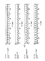
- FIGS. 5A-5D illustrate a case where a spring having a spring constant of 0.935 kgf/mm is used, in which FIG. 5A illustrates an output from the acceleration sensor, FIG. 5B illustrates an output from the magnetic sensor, and FIG. 5C illustrates an output from a pressure sensor, and FIG. 5D illustrates an output from a displacement sensor.
- FIG. 6 illustrates a second-order integration of the acceleration sensor in the case where the spring having a spring constant of 0.935 kgf/mm is used.
- FIGS. 7A and 7B illustrate the case where the spring having a spring constant of 0.935 kgf/mm is used, in which FIG. 7A illustrates a displacement computed on the basis of an output from the magnetic sensor, and FIG. 7B illustrates an output from the displacement sensor.
- FIGS. 8A-8D illustrate a case where a CPR training dummy is used, in which FIG. 8A illustrates an output from the acceleration sensor, FIG. 8B illustrates an output from the magnetic sensor, and FIG. 8C illustrates an output from the pressure sensor, and FIG. 8D illustrates an output from the displacement sensor.
- FIG. 9 illustrates a second-order integration of the acceleration sensor in a case where a CPR training dummy is used.
- FIGS. 10A and 10B illustrate a case where the CPR training dummy is used, in which FIG. 10A illustrates a displacement computed on the basis of an output from the magnetic sensor, and FIG. 10B illustrates an output from the displacement sensor.
- FIG. 11 is a flowchart illustrating a flow of a process performed by the compression depth calculation apparatus.
- FIG. 12 is a flowchart illustrating a flow of the process performed by the compression depth calculation apparatus.
- FIGS. 13A-13C illustrate a modification of a measuring apparatus, in which FIG. 13A is an appearance perspective view, FIG. 13B is a cross-sectional view when viewed in the direction A in FIG. 13A , and FIG. 13C is a plan view (illustration of a voice generating unit, a display unit, and an LED is omitted).
- FIG. 14A schematically illustrates a state in which the compression depth of an object is calculated by using a belt and a cam
- FIG. 14B schematically illustrates a state in which the cam is rotated 90° counterclockwise from the state of FIG. 14A .
- a compression depth calculation system 1000 includes a measuring apparatus 1 and a compression depth calculation apparatus 2 .
- the measuring apparatus 1 includes a receiver coil 11 (magnetic field sensing means), a transmitter coil 12 (magnetic field generating means), an acceleration sensor 13 , a movable portion 14 , a fixed portion 15 , and a spring 16 (resilient member).
- the receiver coil 11 and the transmitter coil 12 are intensively referred to as a magnetic sensor 19 .
- the transmitter coil 12 and the acceleration sensor 13 are arranged on the fixed portion 15 .
- the fixed portion 15 is fixed to a body B of a sick or injured person.
- the method of fixing contemplated is a method using a double-faced adhesive tape, for example.
- the body B has a spring-like property and a damper-like property.
- the spring-like property is dominant, the body B is considered to be approximately a spring 17 having a spring constant of K 1 .
- the receiver coil 11 is arranged on the movable portion 14 so as to face the transmitter coil 12 .
- the spring 16 having a spring constant of K 2 is arranged between the movable portion 14 and the fixed portion 15 .
- the spring 16 is selected so that a relationship of K 2 >K 1 is satisfied. Otherwise, when a compression force F is applied to the movable portion 14 (see FIG. 2 ), the spring 16 is contracted to the shortest length, which limits a range of motion, whereby the function as the magnetic sensor 19 is impaired.
- a distance D between the movable portion 14 and the fixed portion 15 is preferably on the order of 2 mm, for example.
- the following expression (1) and the expression (2) are satisfied; F ⁇ K 1 ⁇ X 1 expression (1) F ⁇ K 2 ⁇ X 2 expression (2) where X 2 is the amount of contraction of the spring 16 when the compression force F is applied to the movable portion 14 , and X 1 is the amount of contraction of the spring 17 . If the distance D is approximately 2 mm, X 2 preferably becomes approximately 0.5 mm.
- an AC oscillation source 31 generates an AC voltage having a specific frequency (for example, 20 kHz).
- the AC voltage is converted to an AC current having a specific frequency by an amplifier 32 , and the converted AC current flows to the transmitter coil 12 .
- a magnetic field generated by the AC current flowing in the transmitter coil 12 generates an induced electromotive force in the receiver coil 11 .
- the AC current generated in the receiver coil 11 by an induced electromotive force (the frequency is the same as the frequency of the AC voltage generated by the AC oscillation source 31 ) is amplified by a preamplifier 33 , and a signal after the amplification is input to a detector circuit 34 .
- the detector circuit 34 the above-described signal after the amplification is detected by a specific frequency or a double frequency generated by the AC oscillation source 31 . Therefore, an output from the AC oscillation source 31 is introduced into a reference signal input terminal of the detector circuit 34 as a reference signal 35 .
- the relationship between a pressure (force F) applied to the movable portion 14 and the magnitude of the voltage expressed by the output signal introduced from the low-pass filter 36 to the drive circuit 21 is as illustrated by a line 4 a (broken line) in FIG. 4 .
- the strength of the magnetic field has a characteristic of attenuating at a rate of square of the distance.
- the reason why the line 4 a extends linearly is that the spring constant K 2 of the spring 16 is large, and the amount of contraction of the spring 16 with respect to the pressure to the movable portion 14 is small, and hence this characteristic may be treated as the linear characteristic.
- the relationship between the pressure and the voltage may have a proportional relationship passing through an original point.
- This correction may be performed by a processing unit 23 described later, for example.
- the compression depth calculation apparatus 2 is a computer apparatus and includes the drive circuits 21 , 22 , the processing unit 23 , a memory unit 24 , a voice generating unit 25 , a display unit 26 , a power source unit 27 , and an input unit 28 .
- acceleration information received from the acceleration sensor 13 of the measuring apparatus 1 is converted into a voltage, and is transmitted to the processing unit 23 .
- the processing unit 23 is realized by, for example, a CPU (Central Processing Unit), and includes a second-order differential waveform creating unit 231 , a waveform comparing unit 232 , a calculating unit 233 , and a determining unit 234 .
- a CPU Central Processing Unit
- the processing unit 23 includes a second-order differential waveform creating unit 231 , a waveform comparing unit 232 , a calculating unit 233 , and a determining unit 234 .
- the processes of these units will be described with reference also to FIG. 3 , FIG. 5 , and FIG. 6 .
- an output from the acceleration sensor 13 becomes as illustrated in (a)
- an output from the magnetic sensor 19 becomes as illustrated in (b)
- an output when a pressure sensor (not illustrated) is used instead of the magnetic sensor 19 becomes as illustrated in (c)
- an output (the true value (correct value) of displacement) from a displacement sensor (not illustrated) such as a laser sensor as a reference becomes as illustrated in (d).
- the target is to obtain information as close as possible to the information illustrated in (d) by using at least one of items of information of the outputs illustrated in (a), (b), and (c).
- the displacement sensor such as a laser sensor
- the output from the acceleration sensor 13 is subjected to a second-order integration, the error of the second-order integration value is increased with time as illustrated in FIG. 6 , and hence it is off from practical use.
- the waveform of the output from the magnetic sensor 19 illustrated in (b) is similar to the waveform of the output from the displacement sensor illustrated in (d). Therefore, by multiplying the waveform of the output from the magnetic sensor 19 illustrated in (b) by a predetermined coefficient of transformation, the waveform of the output from the magnetic sensor 19 may be bordered upon the waveform of the output from the displacement sensor illustrated in (d).
- the waveform of the output from the pressure sensor illustrated in (c) is also the same.
- the second-order differential waveform creating unit 231 creates a second-order differential waveform on the basis of the voltage information obtained from the drive circuit 21 . Specifically, a second-order differential waveform illustrated in (b 1 ) of (b) is created by performing second-order differential process on the output voltage of the magnetic sensor 19 illustrated in (a) as illustrated in FIG. 3 .
- the waveform comparing unit 232 compares the second-order differential waveform illustrated in (b 1 ) in FIG. 3 and an acceleration waveform (the same as the waveform illustrated in FIG. 5( a ) ) on the basis of an output from the acceleration sensor 13 illustrated in (b 2 ).
- the calculating unit 233 performs a variety of calculations, and the determining unit 234 performs a variety of determinations. The detailed description thereof will be given later in conjunction with the description of flowcharts in FIG. 11 and FIG. 12 .
- the memory unit 24 is a unit for memorizing various items of information and, for example, is realized by a RAM (Random Access Memory), a ROM (Read Only Memory), and an HDD (Hard Disk Drive), and so on.
- RAM Random Access Memory
- ROM Read Only Memory
- HDD Hard Disk Drive
- An initial value of the coefficient of transformation in the information memorized therein is an initial value of the coefficient of transformation used until an adequate coefficient of transformation is calculated, and is obtained and input in advance by a user on the basis of experiment or the like.
- a first coefficient and a second coefficient are a lower limit value and an upper limit value in a range of adequate coefficient of transformation values respectively, and are obtained through an experiment or the like and are input in advance by a user.
- a first distance and a second distance are a lower limit value and an upper limit value in, a range of adequate compression depth values respectively, and are input in advance by the user.
- the first distance may be set to “3.8 cm” and the second distance may be set to “5.1 cm”.
- a first time width and a second time width are a lower limit value and an upper limit value in a range of an adequate interval (see FIG. 3( c ) ) respectively, and are obtained through an experiment or the like and are input in advance by the user.
- the voice generating unit 25 is a unit for generating a voice and is realized by a speaker or the like, for example.
- the power source unit 27 is a power source supply unit in the compression depth calculation apparatus 2 .
- the input unit 28 is a unit operated by the user for inputting a variety of items of information and, for example, is realized by a keyboard, a mouse, or the like.
- FIG. 8 to FIG. 10 are the same as FIG. 5 to FIG. 7 except that a CPR training dummy is used instead of the spring.
- the waveform of the output from the magnetic sensor 19 illustrated in (b) is very similar to the waveform of the output from the displacement sensor illustrated in (d).
- the error of the second-order integration value is increased with time, and hence it is off from practical use.
- the (displacement) waveform calculated on the basis of the output from the magnetic sensor 19 illustrated in (a) is similar to the displacement indicated by the output (the true value of displacement) from the displacement sensor illustrated in (b). Other detailed descriptions are omitted.
- the drive circuit 21 acquires voltage information on the basis of the output from the receiver coil 11 from the low-pass filter 36 , and the drive circuit 22 acquires acceleration information from the acceleration sensor 13 (Step S 1 ).
- the second-order differential waveform creating unit 231 creates a second-order differential waveform (see FIG. 3( b ) (b 1 )) from the voltage information on the basis of the output from the receiver coil 11 (Step S 2 ).
- the waveform comparing unit 232 compares the two-order differential waveform (see FIG. 3( b ) (b 1 )) and the acceleration waveform (see FIG. 3( b ) (b 2 )) on the basis of the acceleration sensor 13 (Step S 3 ).
- the output from the acceleration sensor 13 includes a DC component (offset) by a gravitational force field (acceleration 1G (gravity)).
- the second-order differential waveform of the output from the magnetic sensor 19 does not include such an offset. Therefore, at the time of the comparison in Step S 3 , in order to eliminate (or reduce) the error caused by the offset, for example, it is preferred to perform (1) an output from the acceleration sensor 13 is caused to pass through a high-pass filter so as to remove the offset, or (2) an average value of the offset with respect to the output from the acceleration sensor 13 is calculated and subtracted.
- Such an error may be reduced also by causing the both data to pass through the same low-pass filter having a lowered cut-off frequency (for example, a cut-off frequency of approximately 30 Hz).
- a coefficient of transformation ⁇ may be calculated by using the following expression (3) (see FIG. 3( b ) ).
- reference sign Am denotes a second-order differential waveform
- reference sign Aa denotes an acceleration (sensor) waveform
- Reference sign t denotes a certain time width
- ⁇ is a ratio of integration values within a certain time range.
- the coefficient of transformation ⁇ is a ratio of the magnitude of the acceleration waveform (see FIG.
- the ratio of the magnitude may be calculated by a ratio such as amplitude or a power of signal other than the expression (3).
- the determining unit 234 determines whether or not the coefficient of transformation ⁇ calculated in Step S 4 satisfies the following inequality expression (4) (Step S 5 ) and, if satisfied (Yes), the calculated value is used as the coefficient of transformation ⁇ in the following calculation (Step S 6 ) and, if not satisfied (No), the initial value of the coefficient of transformation memorized in the memory unit 24 is used as the coefficient of transformation ⁇ in the following calculation (Step S 7 ).
- Step S 8 the waveform created in Step S 8 is highly accurate.
- the (displacement) waveform created in Step S 8 illustrated in (a) is similar to the displacement indicated by the output (the true value of displacement) from the displacement sensor illustrated in (b), and the waveform crated in Step 8 is highly accurate.
- the calculating unit 233 calculates the compression depth and an interval on the basis of the waveform Dm created in Step S 8 (Steps S 9 , 10 ). This calculation may be realized by the method of the related art.
- the determining unit 234 references the memory unit 24 , determines whether or not the compression depth calculated in Step S 9 is smaller than the above-described first distance (Step S 11 ) and, if smaller (Yes), issues an instruction to the voice generating unit 25 to generate a voice guidance saying “Press Stronger” (Step S 12 ), and goes to Step S 15 and, if not smaller (No), goes to Step S 13 .
- Step S 13 the determining unit 234 references the memory unit 24 , determines whether or not the compression depth calculated in Step S 9 is larger than the above-described second distance and, if larger (Yes), issues an instruction to the voice generating unit 25 to generate a voice guidance saying “Press Softer” (Step S 14 ), and goes to Step S 15 and, if not larger (No), goes to Step S 15 .
- Step S 15 the determining unit 234 references the memory unit 24 , determines whether or not the interval calculated in Step S 10 is smaller than the first time width and, if smaller (Yes), issues an instruction to the voice generating unit 25 to generate a voice guidance saying “Press Slower” (Step S 16 ), and goes to Step S 19 and, if not smaller (No), goes to Step S 17 .
- Step S 17 the determining unit 234 references the memory unit 24 , determines whether or not the interval calculated in Step S 10 is larger than the second time width and, if larger (Yes), issues an instruction to the voice generating unit 25 to generate a voice guidance saying “Press Faster” (Step S 18 ), and goes to Step S 19 and, if not larger (No), goes to Step S 19 .
- Step S 19 the determining unit 234 determines whether or not the compression is terminated and, if the compression is terminated (Yes), the process is ended and, if the compression is not terminated (No), goes to Step S 20 .
- determination of “the compression is terminated” may be made specifically when the output from the magnetic sensor 19 or the acceleration sensor 13 is not continued for a predetermined period (20 seconds, for example), for example.
- Step S 20 the determining unit 234 determines whether or not the initial value of the coefficient of transformation is used as the coefficient of transformation ⁇ . If the initial value of the coefficient of transformation is not used (No in Step S 20 ), the calculating unit 233 acquires voltage information on the basis of the magnetic sensor 19 (Step S 21 ), and then, goes to Step S 8 because calculation of the coefficient of transformation ⁇ anew is not necessary. If the initial value of the coefficient of transformation is used (Yes in Step S 20 ), the procedure goes back to Step S 1 because the calculating unit 233 needs to calculate the coefficient of transformation ⁇ .
- the compression depth can be calculated easily with high degree of accuracy by calculating the coefficient of transformation by comparing the second-order differential waveform created on the basis of the voltage information acquired from the magnetic sensor and the acceleration waveform on the basis of the acceleration information acquired from the acceleration sensor 13 , creating the displacement waveform of the movement of the compressed portion by multiplying the above-described acquired voltage information by the coefficient of transformation, and calculating the compression depth on the basis of the displacement waveform.
- the accuracy may be improved significantly in comparison with the related art in which the two-order integration of the output from the acceleration sensor is performed.
- the compression depth may be calculated with certain degree of accuracy specifically even in a time band in the early period of compression or the like by using the initial value of the coefficient of transformation.
- the calculated compression depth is smaller than the first distance, adequate guidance may be given to a compressing person by generating a voice guidance which encourages the compressing person to increase the strength of compression from the voice generating unit 25 .
- the calculated compression depth is larger than the second distance, adequate guidance may be given to the compressing person by generating a voice guidance which encourages the compressing person to decrease the strength of compression from the voice generating unit 25 .
- FIGS. 13( a ) to ( c ) a modification of the measuring apparatus 1 will be described.
- the same configurations as in FIG. 2 are designated by the same signs and the description is omitted as needed.
- a battery 93 is arranged with respect to a fixed portion 15 a , and a substrate 91 having the acceleration sensor 13 mounted thereon is mounted via four columns 94 , and a base 92 having the transmitter coil 12 mounted thereon is mounted via four columns 95 .
- a movable portion 14 a has a hollow rectangular parallelepiped opened only on a bottom surface, and is movably connected to the fixed portion 15 via four springs 16 a to 16 d (resilient members).
- the receiver coil 11 is arranged on the movable portion 14 a at a position facing the transmitter coil 12 .
- the voice generating unit 25 as a speaker, the display unit 26 and LED (Light Emitting Diode) 26 a are arranged on the upper surface of the movable portion 14 a .
- the LED 26 a is turned ON when a power switch (not illustrated) is ON and is turned OFF when the power switch is OFF, for example.
- the respective springs 16 a to 16 d having a resilient force approximately 1 ⁇ 4 that of the spring 16 illustrated in FIG. 2 may be used. Also, in this manner, since the receiver coil 11 , the transmitter coil 12 , and the acceleration sensor 13 are arranged in a line (coaxially) in the direction of compression (force F), the force applied thereto are equivalent, and hence the sensing accuracy thereof may be improved.
- the noise signal in association with the chest compression may be removed by a method of removing noise in real time by an LMS (Least Mean Square) algorithm or the like by using a compression displacement waveform.
- FIG. 14 another method of usage of the measuring apparatus 1 will be described.
- a compression displacement detecting method on the basis of the compression given by hands has been described.
- a compact vibrating apparatus a piezoelectric element, a mechanical vibrating apparatus, and the like
- estimate the compression displacement detection or the hardness spring constant.
- organ of human body, and industrial products tires, for example
- food vegetables and fruits and the like
- the hardness of the object may be figured out indirectly.
- the measuring apparatus 1 is arranged with respect to the object O as illustrated in the drawing, and a cam 1301 is arranged so as to come into contact with the movable portion 14 .
- the cam 1301 has a shape having a long radius 1303 and rotates counterclockwise about a shaft 1302 .
- a belt 1304 is wound around the object O and the cam 1301 .
- the hardness of the object O, to which the displacement sensor such as the laser sensor cannot be applied may be figured out indirectly by calculating the compression depth thereof.
- this configuration may be applied to a fetal monitor configured to inspect the tightness of abdominal region of pregnant females, for example. In such a case, usage by reducing the pressing amount and combining with an ultrasonic apparatus or the like configured to confirm heart beats or the like of unborn babies is also possible.
- a compact mechanical compressing apparatus such as the piezoelectric element and a magnetic sensor portion can be mounted on a finger tip, it may be used for an application of measurement of the harness of body during the palpation (for example, breast cancer screening or the like) or the hardness measurement of the organ during the operation.
- an extremely-compact compression displacement detection or hardness (spring constant) estimation apparatus may be configured.
- the pressure sensor may be used instead of the magnetic sensor, and the pressure sensor may be of any types in which a piezoelectric element is used, or a strain gauge is used.
- the coefficient of transformation may be calculated by performing the one-order differential further on the both data, calculating jerks thereof respectively, and comparing these jerks instead of comparing the second-order differential waveform obtained by performing the two-order differential on the waveform of the output of the magnetic sensor 19 and the waveform of the output from the acceleration sensor 13 . Accordingly, the error caused by the DC component (offset) caused by the gravitational force field of the output from the acceleration sensor 13 may be eliminated.
- a rectification circuit may be used instead of the detector circuit 34 .
- a continuous sound such as “pi, pi, . . . ” sound for notifying adequate compression timings may be generated by the voice generating unit 25 in addition to the voice guidance for the compressing person.
- Values such as the first coefficient, the second coefficient, the first distance, the second distance, the first time width, and the second time width may be differentiated between babies and adult, or depending on the sex, the height, the weight, and so force.
- a button or the like for selecting such choices may be provided on the compression depth calculation apparatus 2 .
- the spring 16 in the measuring apparatus 1 it is also possible to prepare a plurality of types of springs 16 having different spring constants, and select one for the babies or for the adults and the like.
- the spring 16 has been used as an example of the resilient member in the measuring apparatus 1 , other resilient members such as rubber may be employed instead.
Applications Claiming Priority (3)
| Application Number | Priority Date | Filing Date | Title |
|---|---|---|---|
| JP2010-265073 | 2010-11-29 | ||
| JP2010265073 | 2010-11-29 | ||
| PCT/JP2011/077414 WO2012073900A1 (ja) | 2010-11-29 | 2011-11-28 | 圧迫深度計算システムおよび圧迫深度計算方法 |
Publications (2)
| Publication Number | Publication Date |
|---|---|
| US20130226049A1 US20130226049A1 (en) | 2013-08-29 |
| US9468581B2 true US9468581B2 (en) | 2016-10-18 |
Family
ID=46171832
Family Applications (1)
| Application Number | Title | Priority Date | Filing Date |
|---|---|---|---|
| US13/883,765 Active 2033-11-28 US9468581B2 (en) | 2010-11-29 | 2011-11-28 | Compression depth calculation system and compression depth calculation method |
Country Status (4)
| Country | Link |
|---|---|
| US (1) | US9468581B2 (ja) |
| EP (1) | EP2647365B1 (ja) |
| JP (1) | JP5508545B2 (ja) |
| WO (1) | WO2012073900A1 (ja) |
Families Citing this family (14)
| Publication number | Priority date | Publication date | Assignee | Title |
|---|---|---|---|---|
| US20140323928A1 (en) * | 2013-04-30 | 2014-10-30 | Zoll Medical Corporation | Compression Depth Monitor with Variable Release Velocity Feedback |
| EP3073980A1 (en) * | 2013-11-25 | 2016-10-05 | Koninklijke Philips N.V. | Compensation for deflection in an automated cardiopulmonary compression device |
| JP2015221159A (ja) | 2014-05-23 | 2015-12-10 | 日本光電工業株式会社 | 心肺蘇生アシスト装置 |
| JP6370175B2 (ja) | 2014-09-04 | 2018-08-08 | 日本光電工業株式会社 | 医療機器、医療機器制御方法、及び医療機器連携システム |
| JP6342267B2 (ja) | 2014-09-04 | 2018-06-13 | 日本光電工業株式会社 | 医療機器通信システム、医療機器 |
| US10620101B2 (en) * | 2015-06-25 | 2020-04-14 | Maxell, Ltd. | Durometer |
| US10639234B2 (en) * | 2015-10-16 | 2020-05-05 | Zoll Circulation, Inc. | Automated chest compression device |
| US10729615B2 (en) * | 2015-10-19 | 2020-08-04 | Physio-Control, Inc. | CPR chest compression system with dynamic parameters based on physiological feedback |
| US9805623B1 (en) * | 2016-04-08 | 2017-10-31 | I.M.Lab Inc. | CPR training system and method |
| WO2017221394A1 (ja) * | 2016-06-24 | 2017-12-28 | 富士通株式会社 | 押し込み量測定装置、押し込み量測定方法および押し込み量測定プログラム |
| JP2018086151A (ja) * | 2016-11-29 | 2018-06-07 | 日本光電工業株式会社 | 心肺蘇生アシスト装置 |
| JP6847643B2 (ja) * | 2016-11-29 | 2021-03-24 | 日本光電工業株式会社 | 圧迫深度算出装置 |
| US20190374430A1 (en) * | 2018-06-08 | 2019-12-12 | Defibtech, Llc | Autonomous Mechanical CPR Device |
| CN113768773B (zh) * | 2021-09-07 | 2023-06-13 | 首都医科大学宣武医院 | 一种cpr装置 |
Citations (11)
| Publication number | Priority date | Publication date | Assignee | Title |
|---|---|---|---|---|
| JPH09281125A (ja) | 1996-02-14 | 1997-10-31 | Toyota Central Res & Dev Lab Inc | 回転速度計測装置 |
| US6013041A (en) * | 1998-02-13 | 2000-01-11 | Leathers; Kevin P. | Apparatus and method for simulating therapeutic manipulation |
| US6125299A (en) | 1998-10-29 | 2000-09-26 | Survivalink Corporation | AED with force sensor |
| US6306107B1 (en) | 1999-05-31 | 2001-10-23 | Laerdal Medical As | System for measuring and using parameters during chest compression in a life-saving situation or a practice situation, and also application thereof |
| US20010047140A1 (en) | 2000-02-04 | 2001-11-29 | Freeman Gary A. | Integrated resuscitation |
| US6390996B1 (en) | 1998-11-09 | 2002-05-21 | The Johns Hopkins University | CPR chest compression monitor |
| US20040082888A1 (en) * | 2002-10-25 | 2004-04-29 | Revivant Corporation | Method of determining depth of compressions during cardio-pulmonary resuscitation |
| JP2005046609A (ja) | 2003-06-27 | 2005-02-24 | Zoll Medical Corp | Cpr時の胸部圧迫効果向上のための方法及び装置 |
| US20050101889A1 (en) | 2003-11-06 | 2005-05-12 | Freeman Gary A. | Using chest velocity to process physiological signals to remove chest compression artifacts |
| US20080146974A1 (en) * | 2006-12-15 | 2008-06-19 | Laerdal Medical As | Display unit for providing feedback in CPR |
| US20080208082A1 (en) * | 2007-02-15 | 2008-08-28 | Jon Nysaether | System and method for increased accuracy in determining cpr chest compression depth in real time |
-
2011
- 2011-11-28 WO PCT/JP2011/077414 patent/WO2012073900A1/ja active Application Filing
- 2011-11-28 JP JP2012546864A patent/JP5508545B2/ja active Active
- 2011-11-28 EP EP11845049.3A patent/EP2647365B1/en active Active
- 2011-11-28 US US13/883,765 patent/US9468581B2/en active Active
Patent Citations (15)
| Publication number | Priority date | Publication date | Assignee | Title |
|---|---|---|---|---|
| JPH09281125A (ja) | 1996-02-14 | 1997-10-31 | Toyota Central Res & Dev Lab Inc | 回転速度計測装置 |
| US6013041A (en) * | 1998-02-13 | 2000-01-11 | Leathers; Kevin P. | Apparatus and method for simulating therapeutic manipulation |
| US6125299A (en) | 1998-10-29 | 2000-09-26 | Survivalink Corporation | AED with force sensor |
| US6390996B1 (en) | 1998-11-09 | 2002-05-21 | The Johns Hopkins University | CPR chest compression monitor |
| US6306107B1 (en) | 1999-05-31 | 2001-10-23 | Laerdal Medical As | System for measuring and using parameters during chest compression in a life-saving situation or a practice situation, and also application thereof |
| US20010047140A1 (en) | 2000-02-04 | 2001-11-29 | Freeman Gary A. | Integrated resuscitation |
| US20040082888A1 (en) * | 2002-10-25 | 2004-04-29 | Revivant Corporation | Method of determining depth of compressions during cardio-pulmonary resuscitation |
| US7118542B2 (en) * | 2002-10-25 | 2006-10-10 | Zoll Circulation, Inc. | Devices for determining depth of chest compressions during CPR |
| US7476206B2 (en) * | 2002-10-25 | 2009-01-13 | Zoll Circulation, Inc. | System for estimating the actual ECG of a patient during CPR |
| JP2010214122A (ja) | 2002-10-25 | 2010-09-30 | Zoll Circulation Inc | 心肺蘇生中の胸部圧迫深度を測定する装置 |
| JP2005046609A (ja) | 2003-06-27 | 2005-02-24 | Zoll Medical Corp | Cpr時の胸部圧迫効果向上のための方法及び装置 |
| US7220235B2 (en) * | 2003-06-27 | 2007-05-22 | Zoll Medical Corporation | Method and apparatus for enhancement of chest compressions during CPR |
| US20050101889A1 (en) | 2003-11-06 | 2005-05-12 | Freeman Gary A. | Using chest velocity to process physiological signals to remove chest compression artifacts |
| US20080146974A1 (en) * | 2006-12-15 | 2008-06-19 | Laerdal Medical As | Display unit for providing feedback in CPR |
| US20080208082A1 (en) * | 2007-02-15 | 2008-08-28 | Jon Nysaether | System and method for increased accuracy in determining cpr chest compression depth in real time |
Also Published As
| Publication number | Publication date |
|---|---|
| EP2647365B1 (en) | 2017-03-15 |
| JPWO2012073900A1 (ja) | 2014-05-19 |
| EP2647365A1 (en) | 2013-10-09 |
| JP5508545B2 (ja) | 2014-06-04 |
| EP2647365A4 (en) | 2015-12-30 |
| US20130226049A1 (en) | 2013-08-29 |
| WO2012073900A1 (ja) | 2012-06-07 |
Similar Documents
| Publication | Publication Date | Title |
|---|---|---|
| US9468581B2 (en) | Compression depth calculation system and compression depth calculation method | |
| EP2308448B1 (en) | Method and apparatus for enhancement of chest compressions during CPR | |
| KR101556813B1 (ko) | 심폐소생술을 수행하는 동안, 압박 파라미터들을 측정하는 심폐소생술 보조 장치 | |
| US11944582B2 (en) | Compression depth monitor with variable release velocity feedback | |
| US9649251B2 (en) | Method and system for measuring chest parameters, especially during CPR | |
| EP3430980A1 (en) | An apparatus for measuring a physiological parameter using a wearable sensor | |
| JP2016537139A (ja) | 自動化された心肺圧迫装置における偏向の補償 | |
| US9055893B2 (en) | Degree of hardness measurement system and degree of hardness measurement method | |
| US20210153777A1 (en) | Body motion determination system and biological state monitoring system | |
| CN113692523B (zh) | 生物体信息监测系统、床系统以及生物体信息监测方法 | |
| EP3547903B1 (en) | Compression depth calculating device | |
| US11517502B2 (en) | Cardiopulmonary resuscitation assisting apparatus |
Legal Events
| Date | Code | Title | Description |
|---|---|---|---|
| AS | Assignment |
Owner name: HITACHI, LTD., JAPAN Free format text: ASSIGNMENT OF ASSIGNORS INTEREST;ASSIGNORS:KANDORI, AKIHIKO;OGATA, KUNIOMI;KAWABATA, RYUZO;AND OTHERS;SIGNING DATES FROM 20130401 TO 20130402;REEL/FRAME:030359/0866 |
|
| STCF | Information on status: patent grant |
Free format text: PATENTED CASE |
|
| MAFP | Maintenance fee payment |
Free format text: PAYMENT OF MAINTENANCE FEE, 4TH YEAR, LARGE ENTITY (ORIGINAL EVENT CODE: M1551); ENTITY STATUS OF PATENT OWNER: LARGE ENTITY Year of fee payment: 4 |
|
| MAFP | Maintenance fee payment |
Free format text: PAYMENT OF MAINTENANCE FEE, 8TH YEAR, LARGE ENTITY (ORIGINAL EVENT CODE: M1552); ENTITY STATUS OF PATENT OWNER: LARGE ENTITY Year of fee payment: 8 |